

Page 1
Installation Instructions
Bulletin 1585BP UTP Plug
IMPORTANT: SAVE THESE INSTRUCTIONS FOR FUTURE USE.
Refer to the product catalog pages for additional information.
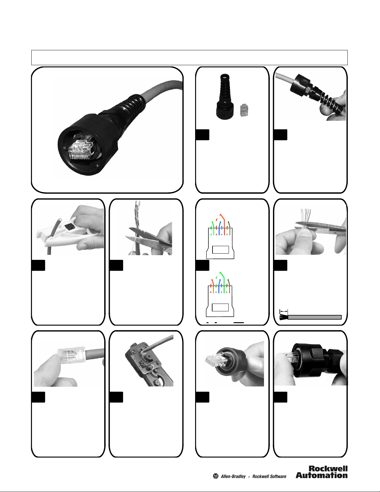
Using a cable stripper,
3 4
remove approximately
38 mm (1.5 in.) of sheathing.
Cut the rip cord as
close to the jacket as
possible. Fan pairs into
proper color code (see next
frame).
Product includes: flex
1
nut, plug assembly,
and modular plug.
T568A
Color Code
Pair 2
Pair 3 Pair 1
18234567
T568B
5 6
Color Code
Pair 3
Pair 1
Pair 2
18234567
Color Key:
Pair 4
1=White/Green
2=Green
3=White/Orange
4=Blue
5=White/Blue
6=Orange
7=White/Brown
8=Brown
Color Key:
Pair 4
1=White/Orange
2=Orange
3=White/Green
4=Blue
5=White/Blue
6=Green
7=White/Brown
8=Brown
=Tip =Ring
Place plug housing
2
over the industrial
cable as shown, flex nut
may need to be loosened.
Note: Outer cable
diameter range 4
(0.160
…
0.315 in.)
…
8mm
After fanning pairs to
proper color code,
hold the pairs close to the
jacket and trim conductors
leaving 12 mm (0.5 in.) extending from the inner jacket.
12 mm
(0.5 in.)
Place modular plug
7 8
over wire ends being
sure to maintain color code.
Insure that the pairs are inserted all the way into the
modular plug including the
inner jacket. The inner jacket should be directly under
the plug’s strain relief tab.
Using a crimp tool
(1585A--JCRIMP),
terminate the modular
plug to the cable.
Slide the plug housing
9 10
up the cable and align
with the modular plug.
1
Insert the modular
plug into the plug
housing. Align the latch with
the LATCH slot, depress
latch and insert plug into
plug housing until it bottoms
out.
Page 2
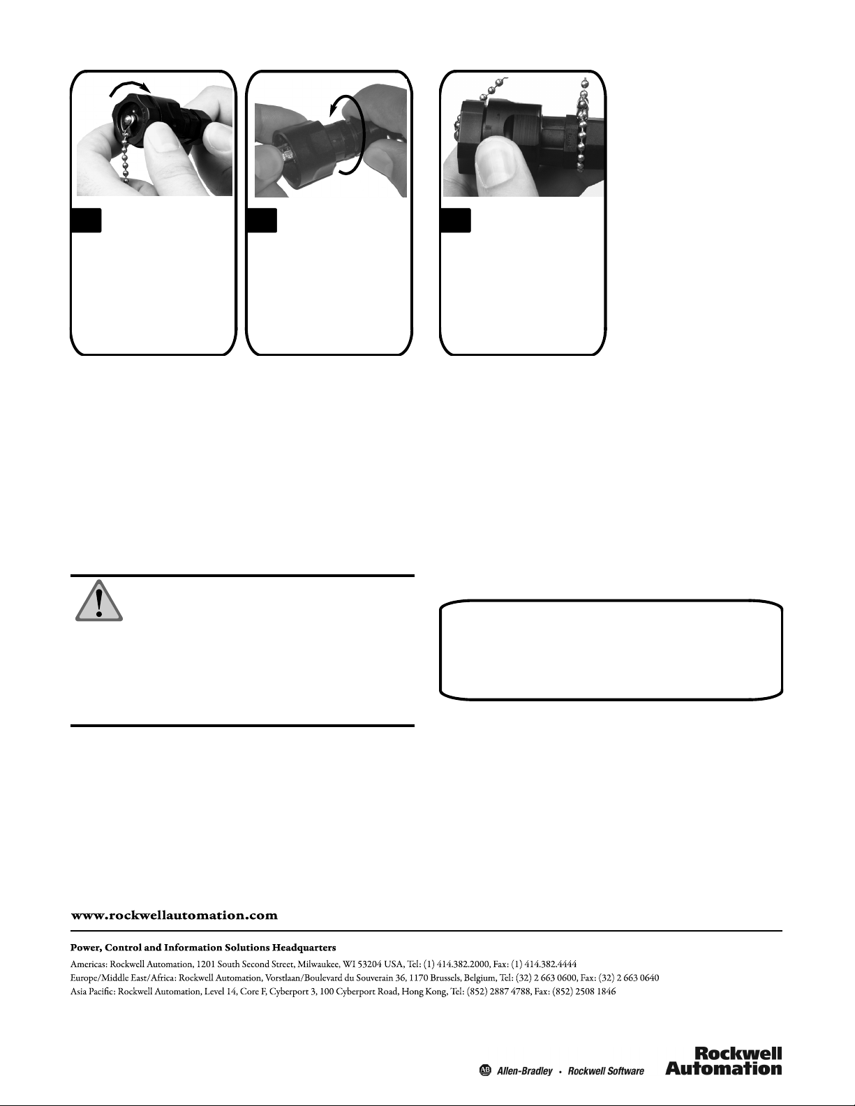
The original dust
11 12
cover (1585BP-MCAP)canbeused
to insure proper
seating of plug.
keeping dust cap engaged,
tighten the flex nut to
0.5 N•m(5 in•lbs).
ATTENTION: To assist safe installation, comply
with the following:
A. Use caution when installing or modifying
telecommunications circuits.
B. Never touch uninsulated wire terminals
unless the circuit has been disconnected.
C. Never install this device in a wet location.
D. Never install wiring during a lightning storm.
While maintaining
pressure on plug or
Place optional dust
13
cap (1585BP--MCAP)
chain over plug housing and
position between flex nut
and plug assembly as
shown. Tighten chain to
secure.
IP67 rating can only be achieved when using
an IP67 rated enclosure with a properly assembled
industrial outlet or industrial plug cap.
PN--26346
PrintedinUSA
2
 Loading...