

Page 1
ENGLISH
DANSKDEUTSCH
ESPAÑOL
FRANCAIS
ITALIANO
G
eneral Information
L
oad, current line voltage, surrounding ambient temperature and
l
oad type are crucial factors when using solid state relays. It is nec-
e
ssary to carry out critical analysis of the application and perform
p
roper calculations when using all Allen-Bradley solid state relay
p
roducts.
Voltage transient protection
Ideal protection is achieved through varistors (metal oxide varistors)
mounted across the power terminals. The varistor voltage has to
match the line voltage of the application. Wrong selection can cause
l
imited protection or hazardous situation on selected models the varistor
i
s mounted internally.
I
MPORTANT
S
hould you require information about installation, operation or mainte-
n
ance of the product that is not covered in this instruction document, contact your local Rockwell Automation sales office or Allen-Bradley distributor. The information in this document is not considered binding on any
product warranty.
W
ARNING
H
azardous Voltage
C
an cause electric shock and burns. Disconnect power before proceeding
w
ith any work on this equipment.
N
ever touch the terminals of the solid state relay if voltage is present at its
i
nput. The output terminals remain live even in the off-state of the semiconductor relay (leakage current, relay breakdown). Heatsink can be hot,
even after removing the power.
G
enerelle oplysninger
B
elastningsstrøm, netspænding, omgivende temperatur og belast-
n
ingstype er afgørende faktorer ved anvendelse af Solid State
r
elæer. Ved al anvendelse af solid State relæer fra Allen-Bradley. Er
d
et nødvendigt at foretage en kritisk analyse af applikationen og at
u
dføre de nødvendige beregninger.
Spændingstransientbeskyttelse
Den ideelle beskyttelse opnås ved at anvende varistorer (zinkoxidvaristorer), der monteres hen over effekt-halvlederen.
Varistorspændingen skal svare til netspændingen i applikationen.
F
orkert valg kan medføre nedsat beskyttelse eller en farlig situation.
V
IGTIGT:
H
vis du ønsker oplysninger om installation, drift eller vedligeholdelse af
d
ette produkt, som ikke er omfattet af denne vejledning, bedes du hen-
v
ende dig til en af vore forhandlere eller direkte til Rockwell Automation
sales office o Allen-Bradley. Oplysningerne i dette dokument kan ikke
betragtes som bindende i forbindelse med nogen form for produktgaranti.
A
DVARSEL
F
arlig spænding
K
an forårsage elektriske stød og forbrænding. Afbryd forsyningsspændin-
g
en helt, hvis der skal arbejdes på dette udstyr. Berør aldrig terminalerne
p
å Solid State Relæet,hvis der er forbundetspænding til indgangstermi-
n
alerne. Udgangsterminalerne er strømførende,selv om styrespændingen
er afbrudt. (Lækstrøm i udgangstrin eller ved evt.kortslutning i relæet.)
Allgemeine Informationen
Laststrom, Netzspannung, Um-gebungstemperatur und Art der Last
sind entscheidende Kriterien bei der Verwendung von
Halbleiterrelais. Es ist unbedingt erforderlich, eine sorgfältige
Analyse der Anwendung und präzise Berechnungen durchzuführen,
um ein für den Einsatz passendes Gerät aus-wählen zu können.
Überspannungsschutz
Ein idealer Schutz wird durch parallel zum Halbleiter geschaltete
Varistoren (Metalloxid-Varistoren) erzielt. Die Varistoren sind
entsprechend der Netz-spannung der jeweiligen Anwendung
auszulegen. Eine falsche Auswahl kann zu verminderten Überspannungsschutz des Halbleiterrelais oder einer Überhitzung des Varistors führen.
WICHTIG
Sollten Sie Informationen zu Einbau, Betrieb und Wartung des Relais
benötigen, die hier nicht beschrieben sind, so wenden Sie sich bitte an
Rockwell Automation sales office oder Allen-Bradley distributor. Mit den
Informationen dieses Beipackzettels ist keine Produktgarantie ver-bunden.
WAARSCHUWING
Gefährliche Spannung, die einen Stromschlag oder Verbrennung verursachen können. Entfernen Sie die Versorgungsspannung bevor Sie an
dem Gerät arbeiten.
Berühren Sie niemals die Anschlussklemmen, wenn die Betriebsspannung
vorhanden sein kann. ie Ausgangsklemmen sind auch bei abgeschaltetem
Halbleiterrelais spannungsführend!
Información general
La corriente de carga, la tensión de línea, la temperatura ambiente y
el tipo de carga son factores importantes cuando se utilizan relés de
estado sólido. Es necesario llevar a cabo un análisis crítico de la
aplicación y realizar cálculos apropiados al utilizar los relés de estado sólido de Allen-Bradley.
Protección contra transitorios de tensión.
La protección óptima se obtiene por medio de va-ristores (varistores
de óxido metálico) montados en paralelo al semiconductor de
potencia. La tensión del varistor tiene que ser ligeramente superior
a la tensión de línea de su aplicación (tensión 400V, tensión del varistor
420V). Una selección equivocada puede limitar la protección o causar una
situación peligrosa.
IMPORTANTE
En caso de necesitar información sobre la instalación, funcionamiento o
mantenimiento del producto que no venga reflejada en el presente documento consulte con un representante autorizado de Rockwell Automation
o Allen-Bradley. La información de este documento no se considera vinculante en ninguna garantía del producto.
ADVERTENCIA
Tensiones peligrosas que pueden provocar descargas eléctricas y quemaduras. Desconecte siempre la tensión antes de manipular el equipo. No
toque nunca los terminales del relé estático si hay tensión en sus entradas.
Los terminales de salida tienen tensión aunque el semiconductor no esté
funcionando (corriente de fuga, rotura del relé).
Généralités
Le courant de charge, la tension de ligne, la température ambiante
et le type de charge sont tous des facteurs décisifs dans l'utilisation
des relais statiques. Il est nécessaire d'effectuer une analyse critique
de l'application et de réaliser tous les calculs nécessaires pour le
choix des relais Allen-Bradley.
Protection contre les tensions transitoires
La protection idéale est obtenue à l'aide de varistances (varistances
à oxyde métallique) montées à travers le semi conducteur. La tension de varistance doit correspondre à la tension de ligne de votre
application. Un mauvais choix peut avoir pour résultat une protection limitée ou une situation dangereuse.
IMPORTANT
Pour toute instruction de montage, de fonctionnement ou de maintenance
du relais ne figurant pas dans le présent document, consulter un agent
Rockwell Automation o Allen-Bradley agréé. Les informations figurant
dans ce document ne peuvent être considérées comme étant liées à la
garantie du produit.
AVERTISSEMENT
Tension dangereuse
Peut causer des chocs électriques et des brûlures. Débrancher
'alimentation avant d'effectuer toute manipulation sur cet équipement. Ne
jamais toucher les bornes du relais statique si la tension est présente sur
l'entrée. La tension reste présente, même si la commande n'est pas
activée (courant de fuite, relais au repos).
Informazioni Generali
La corrente di carico, la tensione di linea, la temperatura ambiente
ed il tipo di carico sono parametri fondamentali per il funzionamento del relè statico. E' necessario effettuare un'analisi critica dell'applicazione e calcoli adeguati nell'utilizzo del dispositivo statico AllenBradley
Protezione dai transitori di tensione
La protezione ideale è ottenuta tramite i varistori montati attraverso
il semiconduttore di alimentazione. La tensione del varistore deve
essere proporzionata alla tensione di linea presente nell'appli-
cazione. L'errata selezione del varistore può causare una protezione limitata ed una situazione di pericolo.
IMPORTANTE
Se sono necessarie informazioni riguardanti l'installazione, il funzionamento o la manutenzione del prodotto non contenute all'interno di questo
manuale si consiglia di fare riferimento ad un tecnico della Rockwell
Automation o Allen-Bradley. Le informazioni contenute in questo documento non modificano in nessun modo gli accordi contrattuali di garanzia.
AVVERTENZA
Tensione elevata può provocare scariche elettriche e bruciature. Togliere
l’alimentazione prima di procedere con qualsiasi intervento sull’apparecchiatura. Non toccare i terminali del relay quando i terminali di ingresso
sono in tensione.
I terminali di uscita restano in tensione anche se il relay è in posizione off
(dispersione di corrente, cedimento del relay).
Operating Instructions
Kom godt i gang
Betriebsanleitung
Notice d’utilisation Instrucciones
Istruzioni d’uso
Bulletin 156
Bulletin 156(0109)
Single Phase
Solid State Contactors
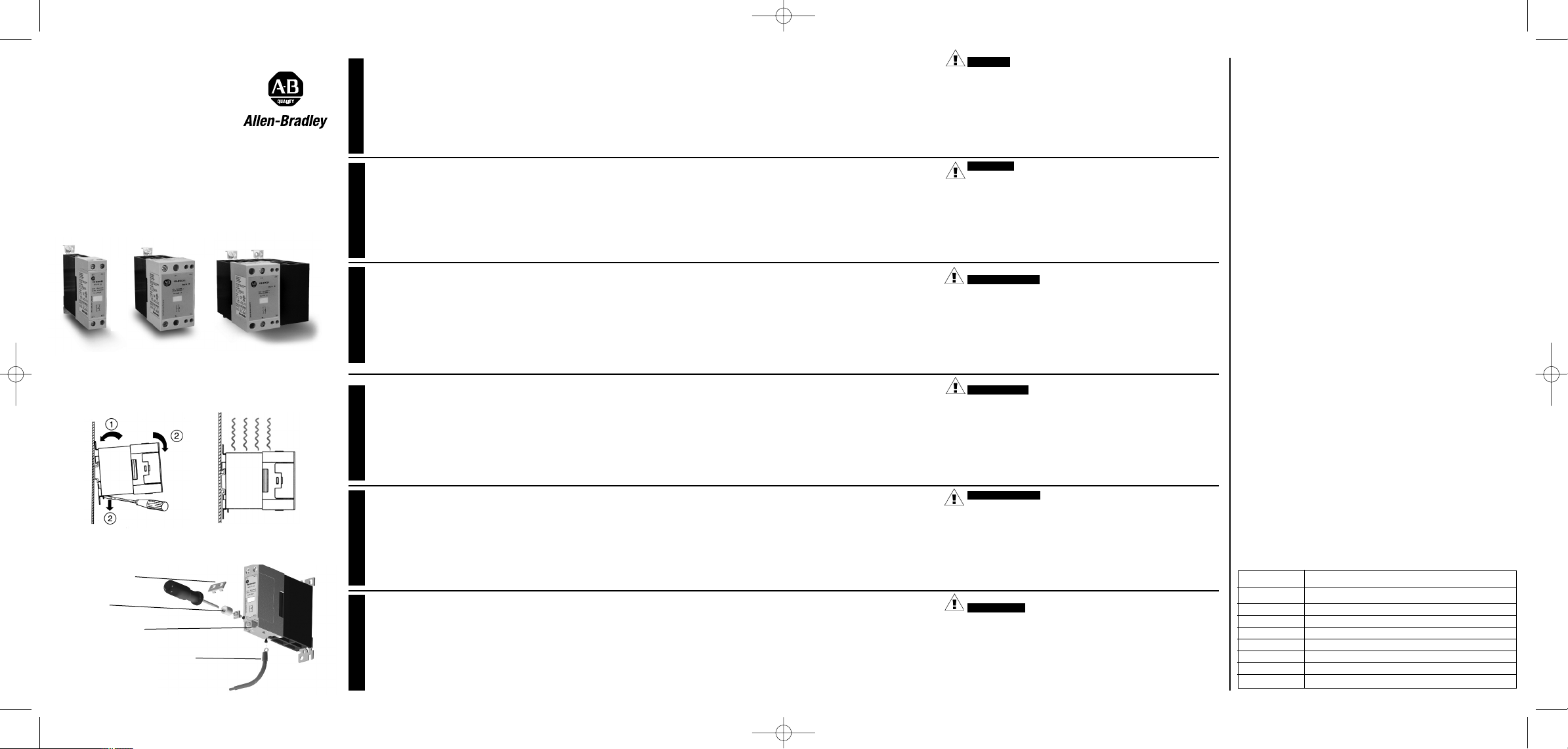
Removable IP20 cover
4mm2cable with crimped ring terminal (lug)
Extraction notch for cover
Retainer sleeve
Installation | Installation | Montage | Installationsbeispiel
Instalación | Installazione
Mounting | Montering | Montage | Anschlußbeispiel
Montaggio | Montaje
Fuse Rating
Short Circuit Protection according to UL508.
Suitable for use on a circuit capable of delivering not more than
65,000Arms symmetrical amperes, 600 volts maximun when protected by
Class J fuses.
The maximum allowed curret value of the fuses is reported in the table
b
elow.
Sikrings værdi
K
ortslutnings beskyttet ihlt. UL508
Passer til forsyning, som ikke kan levere mere end en 65,000Arms symmetrisk ampere, 600 volt maximum når beskyttet med sikringer (Class J).
Den højst tiladte værdi af sikringere, er angivet i tabellen nedenfor.
Auslegung der Sicherung
Kurzschlußschuß nach UL508.
Geeignet für den Einsatz in Schaltanlagen die Abgesichert einen maxi-
malen symmetrischen Strom von 65.000 Aeff und eine maximale
Spannung von 600 Veff lieferen (class J).
Der maximal zulässige Strom der Sicherungen ist in der folgenden Liste zu
finden.
Valor del Fusible
Protección contra cortocircuitos según UL508.
Válido para ser utilizado en un circuito cuya intensidad máxima de corto-
circuito sea 65.000Arms amperios simétricos, 600 V máximo si está protegido por fusibles (Class J)
El máximo valor de intensidad de los fusibles se muestra en la siguiente
tabla.
Type de Fusible
Protection aux court-circuit suivant UL 508.
Adapté pour un circuit ne délivrant pas plus de 65000A efficace, 600volts
maximum avec protection par fusibles (Classe J)
Courant maximum admissible par les fusibles, voir table ci-dessous
Classe Fusibile
Protezione da cortocircuito secondo la UL508.
Adatto per l'utilizzo su un circuito in grado di condurre non più di
65.000Arms simmetrici, massimo 600 volts quando è protetto da fusibili
classe J.
Il valore di corrente massimo dei fusibili è riportato nella tabella di seguito.
Type Maximum allowed ampere rating of the fuse
156-B20...1 20A
156-B30...1 40A
156-B40...1 40A
156-B45...1 60A
156-B50...1 90A
156-B70...1 90A
156-B75...1 90A
156-B90...1 90A
AB_RJ1A_2(150511).qxp:RJ1A_inst_leaf051207.qxd 5/22/11 11:40 AM Page 1
Page 2
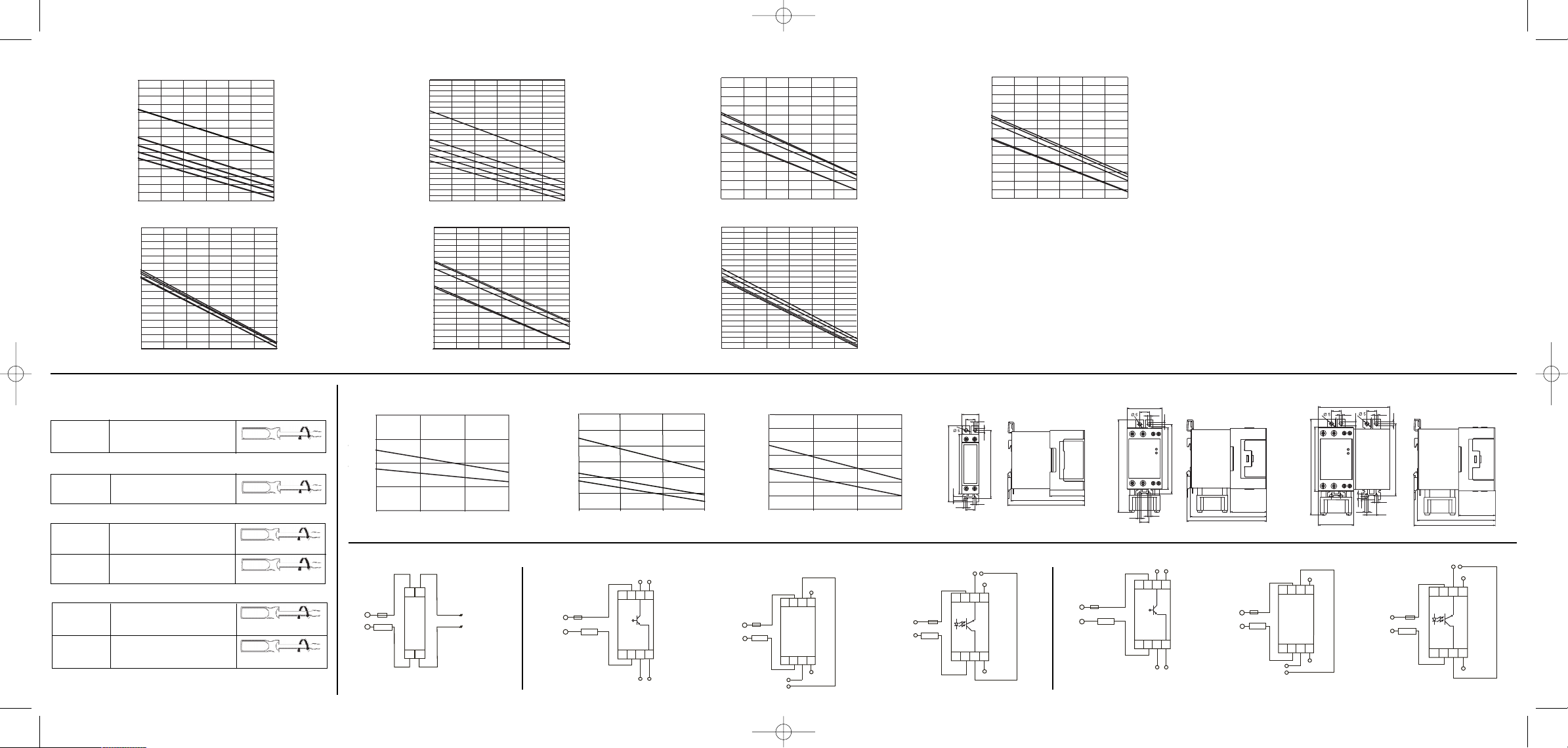
40˚C 45˚C 50˚C 55˚C 60˚C 65˚C 70˚C
22.5mm| 10.0mm
6.0mm
3.0mm| 0.0mm
40˚C 45˚C 50˚C 55˚C 60˚C 65˚C 70˚C
22.5mm
10.0mm
6.0mm
3.0mm
0.0mm
40˚C 45˚C 50˚C 55˚C 60˚C 65˚C 70˚C
22.5mm
10.0mm
6
.0mm
3.0mm
0.0mm
92A
90A
88A
86A
8
4A
82A
80A
78A
76A
74A
7
2A
70A
68A
66A
64A
62A
6
0A
58A
56A
54A
52A
50A
48A
40˚C 45˚C 50˚C 55˚C 60˚C 65˚C 70˚C
22.5mm
10.0mm
6
.0mm
3.0mm
0
.0mm
4
6A
44A
4
2A
40A
38A
3
6A
34A
32A
30A
28A
2
6A
24A
22A
2
0A
40˚C 45˚C 50˚C 55˚C 60˚C 65˚C 70˚C
2
2.5mm
10.0mm
6
.0mm
3.0mm
0.0mm
76A
74A
7
2A
70A
68A
66A
64A
62A
60A
5
8A
56A
54A
5
2A
50A
48A
46A
44A
42A
40A
3
8A
36A
31A
30A
29A
28A
27A
26A
25A
24A
23A
22A
21A
20A
1
9A
1
8A
17A
16A
15A
14A
13A
12A
11A
1
0A
9
A
7
2A
70A
68A
66A
64A
6
2A
60A
58A
56A
5
4A
52A
50A
48A
46A
4
4A
42A
40A
38A
40˚C 45˚C 50˚C 55˚C 60˚C 65˚C 70˚C
22.5mm
10.0mm
6.0mm
3.0mm
0.0mm
52A
50A
48A
4
6A
4
4A
42A
40A
38A
3
6A
3
4A
32A
30A
28A
2
6A
2
4A
40˚C 45˚C 50˚C 55˚C 60˚C 65˚C 70˚C
22.5mm
1
0.0mm
6.0mm
3.0mm
0.0mm
2
1A
2
0A
1
9A
18A
17A
16A
15A
14A
13A
12A
11A
10A
9A
8A
7A
6A
156-B50...1
1
56-B30...1
1
56-B20...1
1
56-B45...1
156-B90...1
Terminal Layout | Terminalfordeling | Exemple de Raccordement | Anschlußbeispiel | Collegamenti Elettrici | Ejemplo de Conexión
Cable Sizes | Kabel Grootte | Tailles de Câble | Kabelgrößen
Tamaños del Cable | Dimensioni del Cavo
Derating by Spacing | Laststrom in Abhängigkeit vom Geräteabstand | Déclassement en fonction de l'écartement de chaque relais | Curva de reducción | Riduzione delle prestazioni in base alla distanza tra i disposittivi
~
Control Input
(+,~)
LOAD
4A22T1
3A11L1
~
(-,~)
Derating Curve | Begrænsningskurve | Courbe de Déclassement | Strombelastbarkeit | Curva Caratteristica | Curva de Reducción
Dimensions | Dimensioner| Dimensions | Abmessungen | Dimensioni | Dimensiones
20/ 30 Amp
156-B75...1
156-B70...1
RJ MINI
RJ MIDI
40
30
20
10
0
40 50 60 70
20A
30A
AACrms
˚C
AACrms
20
30
40
50
60
70
80
40 50
60
70
30
40
50
60
70
80
90
100
˚C
AACrms
90A
70A
˚C
RJ POWER
40
50
60 70
50A
75A
45A
~
~
Over-temperature alarm output
Max voltage: 50VDC
Max current: 50mA
24-275 VAC
Example (AC control without fan)
+
-
2T1
1L1 3A15A3
4A26A4
24-275 VAC
LOAD
~
~
~
~
2T1
1L1 3A15A3
4A26A4
~
~
+
-
24-275 VAC
Example (AC control with fan)
Note: Over-temperature
alarm output
not available in this option
Fan supply input
24VDC, 200mA
LOAD
24-275 VAC
Over-temperature alarm output
Max voltage: 50VDC
Max current: 50mA
Example (DC control with fan)
~
~
LOAD
+
+
4-32VDC
0V
Fan supply Input
24 VDC, 200mA
-
2T1
1L1 3A15A3
4A26A4
Ex
45/ 50/ 75 Amp
45/ 50/ 75 Amp
~
~
Over-temperature alarm output
Max voltage: 50VDC
Max current: 50mA
24-275 VAC
Example
(AC control without fan)
+
-
2T1
1L1 3A15A3
4A26A4
24-275 VAC
LOAD
~
~
~
~
2T1
1L1 3A15A3
4A26A4
~
~
+
-
24-275 VAC
Example (AC control with fan)
Note: Over-temperature
alarm output
not available in this option
Fan supply input
24VDC, 200mA
LOAD
24-275 VAC
~
~
LOAD
+
+
Over-temperature alarm output
Max voltage: 50VDC
Max current: 50mA
4-32VDC
Example (DC control with fan)
0V
Fan supply Input
24 VDC, 200mA
-
2T1
1L1 3A15A3
4A26A4
70/90 Amp
70/90 Amp
12.4
122
45
12.4
4.4
4.4
4.8
4.8
4.4
90
12
12
4.4
4.4
91.6
5.4
122
81.7
4.4
4.4
4.4
4.4
12
45
4.8
91.6
98.7
103
46.5
98.6
4.4
4.8
5.4
102.5
80
91.6
12.5
2
2.5
1
2
103
46.5
98.6
103
46.5
98.6
20/ 30 Amp
20/ 30 Amp (IEC)
L1, T1, A1, A2 Min. 1 x 0.5mm
2
(1 x AWG20)
Max. 2 x 2.5mm
2
(2 x AWG14)
45/ 50/ 70/ 75/ 90 Amp (IEC)
L1, T1 Min. 1 x 4mm
2
(1 x AWG12)
Max. 1 x 25mm2(2 x AWG3)/
2 x 10mm
2
(2 x AWG6)
A1, A2, Min. 1 x 0.5mm
2
(1 x AWG20)
A3, A4 Max. 1 x 4mm2(1 x AWG12)/
2 x 2.5mm
2
(2 x AWG14)
20/ 30 Amp (UL)
L1, T1, A1, A2 18AWG - 14AWG Str & Sol
2 x 14 AWG Str & Sol
45/ 50/ 70/ 75/ 90 Amp (UL)
L1, T1 12AWG - 3AWG Str
12AWG - 10AWG Sol
2 x 10AWG Sol
A1, A2, 18AWG - 12AWG Str & Sol
A3, A4 2 x 14AWG Str & Sol
2Nm with Posidrive 1 bit
2Nm
2.5Nm with Posidrive 2 bit
0.6Nm with Posidrive 0 bit
0.6Nm
2.5Nm
To use 75deG copper (CU) conductor only. Wire size and terminal tightening
torque as per above tables.
DIR 10000175598 (VERSION 00)
AB_RJ1A_2(150511).qxp:RJ1A_inst_leaf051207.qxd 5/22/11 11:40 AM Page 2
 Loading...