

Page 1
ENGLISH
DANISH DEUTSCH ESPAÑOL FRANCAIS ITALIANO
General Information
Load, current line voltage, surrounding ambient temperature and load type
a
re crucial factors when using solid state relays.It is necessary to carry out
critical analysis of the application and perform proper calculations when
using all Allen-Bradley solid state relay products.
IMPORTANT
Should you require information about installation, operation or maintenance
o
f the product that is not covered in this instruction document, contact your
local Rockwell Automation sales office or Allen-Bradley distributor. The information in this document is not considered binding on any product warranty.
WARNING
H
azardous Voltage
Can cause electric shock and burns. Disconnect power before proceeding
with any work on this equipment.
N
ever touch the terminals of the solid state relay if voltage is present at its
input. The output terminals remain live even in the off-state of the semiconductor relay (leakage current, relay breakdown). Heatsink can be hot, even
a
fter removing the power.
Status Monitoring
• The standard product has one GREEN control LED and one RED load
LED. In the voltage controlled version, the green LED indicates that the low
voltage supply is available. Whenthe control signal is very close to ground,
it will turn ON with low intensity to indicate that the load is OFF. When the
control signal is applied, this LED will turn fully ON. In the current mode,
this LED turns ON when the control signal is applied. • The red LED indicates that power is being delivered to the load. If a phase loss occurs, this
LED will be OFF.
Getting Started
• Make sure that the high voltage supply load is OFF. Select the desired
mode of operation. If the device is voltage controlled apply a supply of 24V
DC/AC to terminals 6A4+ and 4A2-, paying attention to polarity if a DC supply is used.
• Apply the control signal (4-20mA or 0-10V DC) to terminals 5A3- and
3A1+, paying attention to polarity. During installation, it is advisable to apply
either 0V or 4mA so that the device is OFF. In the current version, the
GREEN LED will be ON. In the voltage version, the GREEN LED will be
OFF if the high voltage supply was initially OFF. Connect the LIVE phase to
terminal 1L1. Connect the load between the Neutral/ Phase2 and terminal
2T1.
• Turn ON the high voltage supply load. In the voltage version, the GREEN
LED should turn ON and dim if the control signal is 0V. Vary the control signal according to the required power output and the RED LED will turn ON
accordingly when power is supplied to the load.
Notes:
The mode of operation can be changed during operation. During operation,
when the high voltage supply fails, the RED led will turn OFF even though
the control signal is greater than 0V or 4mA.
Voltage transient protection
Ideal protection is achieved through varistors (metal oxide varistors) mounted across the power terminals. The varistor voltage has to match the line
voltage of the application. Wrong selection can cause limited protection or
hazardous situation on selected models the varistor is mounted internally.
Fuse Rating
Short Circuit Protection according to UL508.
Suitable for use on a circuit capable of delivering not more than 65,000Arms
symmetrical amperes, 600 volts maximun when protected by Class J fuses.
The maximum allowed curret value of the fuses is as follows:
• 156-B30..1 : 30A
• 156-B50..1 : 90A
The device is suitable for Pollution Degree 2.
Generelle oplysninger
Belastningsstrøm, netspænding, omgivende temperatur og belastningstype
e
r afgørende faktorer ved anvendelse af Solid State relæer. Ved al anvendelse af solid State relæer fra Allen-Bradley. Er det nødvendigt at foretage
en kritisk analyse af applikationen og at udføre de nødvendige beregninger.
VIGTIGT:
H
vis du ønsker oplysninger om installation, drift eller vedligeholdelse af
dette produkt, som ikke er omfattet af denne vejledning, bedes du henvende dig til en af vore forhandlere eller direkte til Rockwell Automation
s
ales office o Allen-Bradley. Oplysningerne i dette dokument kan ikke
betragtes som bindende i forbindelse med nogen form for produktgaranti.
A
DVARSEL
Farlig spænding
Kan forårsage elektriske stød og forbrænding. Afbryd forsyningsspænding
en helt, hvis der skal arbejdes på dette udstyr. Berør aldrig terminalerne
på Solid State Relæet,hvis der er forbundetspænding til indgangsterminalerne. Udgangsterminalerne er strømførende,selv om styrespændingen
e
r afbrudt. (Lækstrøm i udgangstrin eller ved evt.kortslutning i relæet.)
Funktionsindikering
Standard produktet har en GREEN kontrol LED og en RED belastning LED.
I den spændingskontrollerede udgave indikerer den grønne led,at
lavspændingsforsyning er til rådighed. • Når kontrolsignalet er tæt på nul,vil
den tænde med svag styrke,til indication af,at belastningen er off.Når kontrolsignalet er tilsluttet,vil den lyse med fuld styrke I den strømkontrollerede
udgave vil denne lysdiode tænde,når kontrolsignalet er tilsluttet. • Den røde
led indikerer,at der leveres spænding til belastningen. • Hvis der optræder
et fasebrud ,vil den røde led slukke.
OPSTART
• Sørg for, at den høje spænding belastning er OFF. Vælg den ønskede
driftsform. Hvis enheden er Spændingsstyret anvende en forsyning af 24V
DC/AC til terminaler 6A4 + og 4A2-, vær opmærksom på polariteten er korrekt, hvis en jævnstrømsforsyning anvendes.
• Forbind styresignalet (4-20mA eller 0-10V DC) til terminaler 5/A3 og
3/A1+, vær opmærksom på korrekt polaritet. Det anbefales, uden installationen, at anvende enten 0V eller 4mA således at enheden er slukket. I version hvor strøm bruges som styresignal, vil den grønne LED vil være tændt.
I spændings (0-10V) versionen, vil den grønne LED være slukket, hvis
effekt spændingen oprindeligt var slukket. Tilslut belastning FaseL1 mellem
terminal 1L1 og Nul/FaseL2 til terminal 2T1.
• Tilslut spænding i effekt delen. I spænding version, vil den grønne LED
tænde og dimme hvis styresignal er 0V. Variere kontrol signal i henhold til
den krævede effekt og den røde LED tændes i overensstemmelse hermed,
når der leveres strøm til belastningen.
BEMÆRK:
Funktionsmåden kan ændres under drift.Hvis belastningsspændingen
svigter under drift,vil den rode led slukke,også selv ,også selv om
styreindgangen er påtrykt et signal større
end 0v eller 4 mA.
Spændingstransientbeskyttelse
Den ideelle beskyttelse opnås ved at anvende varistorer (zinkoxid-varistorer), der monteres hen over effekt-halvlederen. Varistorspændingen skal
svare til netspændingen i applikationen. Forkert valg kan medføre nedsat
beskyttelse eller en farlig situation.
Sikrings værdi
Kortslutnings beskyttet ihlt. UL508
Passer til forsyning, som ikke kan levere mere end en 65,000Arms sym-
metrisk ampere, 600 volt maximum når beskyttet med sikringer (Class J).
Den højst tiladte værdi af sikringerne er:
• 156-B30..1 : 30A
• 156-B50..1 : 90A
Enheden er egnet til Forureningsgrad 2
Allgemeine Informationen
Laststrom, Netzspannung, Um-gebungstemperatur und Art der Last sind
e
ntscheidende Kriterien bei der Verwendung von Halbleiterrelais. Es ist
unbedingt erforderlich, eine sorgfältige Analyse der Anwendung und präzise
Berechnungen durchzuführen, um ein für den Einsatz passendes Gerät
a
us-wählen zu können.
WICHTIG
S
ollten Sie Informationen zu Einbau, Betrieb und Wartung des Relais
benötigen, die hier nicht beschrieben sind, so wenden Sie sich bitte an
Rockwell Automation sales office oder Allen-Bradley distributor. Mit den
I
nformationen dieses Beipackzettels ist keine Produktgarantie ver-bunden.
W
AARSCHUWING
Gefährliche Spannung, die einen Stromschlag oder Verbrennung verursachen können. Entfernen Sie die Versorgungsspannung bevor Sie an
d
em Gerät arbeiten.
Berühren Sie niemals die Anschlussklemmen, wenn die Betriebsspannung
vorhanden sein kann. ie Ausgangsklemmen sind auch bei abgeschaltetem
H
albleiterrelais spannungsführend!
Signalisierung
• Das standard Gerät hat eine grüne kontroll LED und eine rote LED zur
Lastanzeige. • Bei schwacher Leuchtstärke wird eine geringe
Steuerspannung Strom und somit Aufsteuerung signalisiert. Bei voller
Steuerspannung ist die grüne LED auf voller Intensität. Die rote LED signalisiert die Aufsteuerung des Lastkreises. • Wenn die Lastspannung fehlt, ist
die rote LED dauerhaft ausgeschaltet.
Inbetriebnahme
• Bitte beachten Sie, dass die Lastspannungsversorgung ausgeschaltet ist.
Selektieren Sie die gewünschte Betriebsart. Die Versorgungsspannung
von 24V DC/AC an den Klemmen 6A4+ und 4A2 aufzuschalten (bei DC
Ansteuerung ist auf die Polarität zu achten).
• Das Steuersignal (4-20mA oder 0-10V DC) ist an den Klemmen 5A3- und
3A1+ aufzulegen (Polarität beachten). Wir empfehlen bei Installation ein 0
bzw. 4mA Signal, damit das Gerät nicht aufgesteuert wird. In der
Stromgesteuerten Version ist die grüne LED aktiv. In der
Spannunggesteuerten Version ist die grüne LED ausgeschaltet insofern die
Lastspannung ausgeschaltet ist. Verbinden Sie die Netzspannung an 1L1.
Verbinden Sie die Last mit 2T1 sowie mit Phasen / oder Neutralleiter.
• Schalten Sie Lastspannungsversorgung ein. In der
Spannungsgesteuerten Version leuchtet die grüne LED und erlischt aufgrund der Steuerspannungsvorgabe von 0V. Stellen Sie das Steuersignal
entsprechend ein (grüne LED proportional zu Vorgabe; rote LED bei aktiver Last).
Information:
Der Funktionswahlschalter kann während des Betriebes verändert werden.
Wenn die Steuerspannung fehlt, erlischt die rote LED, auch wenn die
Steuerspannung >0V ist.
Überspannungsschutz
Ein idealer Schutz wird durch parallel zum Halbleiter geschaltete Varistoren
(Metalloxid-Varistoren) erzielt. Die Varistoren sind entsprechend der Netzspannung der jeweiligen Anwendung auszulegen. Eine falsche Auswahl
kann zu verminderten Überspannungsschutz des Halbleiterrelais oder einer
Überhitzung des Varistors führen.
Auslegung der Sicherung
Kurzschlußschuß nach UL508.
Geeignet für den Einsatz in Schaltanlagen die Abgesichert einen maxi-
malen symmetrischen Strom von 65.000 Aeff und eine maximale
Spannung von 600 Veff lieferen (Class J).
Der maximal zulässige Strom der Sicherungen ist wie folgt:
• 156-B30..1 : 30A
• 156-B50..1 : 90A
Das Gerät ist für Verschmutzungsgrad 2 geeignet.
Información general
La corriente de carga, la tensión de línea, la temperatura ambiente y el tipo
d
e carga son factores importantes cuando se utilizan relés de estado sólido. Es necesario llevar a cabo un análisis crítico de la aplicación y realizar
cálculos apropiados al utilizar los relés de estado sólido de Allen-Bradley.
IMPORTANTE
En caso de necesitar información sobre la instalación, funcionamiento o
m
antenimiento del producto que no venga reflejada en el presente documento consulte con un representante autorizado de Rockwell Automation
o Allen-Bradley. La información de este documento no se considera vincul
ante en ninguna garantía del producto.
A
DVERTENCIA
Tensiones peligrosas que pueden provocar descargas eléctricas y quemaduras. Desconecte siempre la tensión antes de manipular el equipo. No
t
oque nunca los terminales del relé estático si hay tensión en sus entradas.
Los terminales de salida tienen tensión aunque el semiconductor no esté
funcionando (corriente de fuga, rotura del relé).
Indicación de estado
• El equipo estándarconstade un LED verde para control y un LED rojo para
carga. En la versión de control por tensión (0-10V), el LED verde indica que
se está aplicando tensión en la entrada de control. Cuando la señal de control
está muy próxima a 0V, se iluminará con baja intensidad para indicar que la
carga está desconectada. Cuando se aplica la señal de control, este LED se
iluminará con intensidad. En la versión de control por intensidad (4-20mA),
este LED se ilumina cuando se aplica la señal de control. El LED rojo indica
que la potencia se está suministrando a la carga. Si se produce una pérdida
de fase, este LED se apagará.
Iniciación
• Asegúrese de que la alimentación de la carga está desconectada.
Seleccione el modo de operacióndeseado.Si el equipoes de controlpor tensión, aplique una alimentaciónde 24 V CC/CA a los terminales 6A4+ y 4A2-,
prestandoatencióna la polaridad, si se usa una alimentación CC.
• Conecte la señal de control (4-20 mA o 0-10 VCC) a los terminales 5A3y 3A1+, prestando atención a la polaridad. Durante la instalación, se aconseja aplicar bien 0V o 4mA para que la carga comience desconectada. En
la versión de control por intensidad, el LED verde estará iluminado. En la
versión de control por tensión, el LED verde estará apagado si la alimentación estaba inicialmente desconectada. Conecte la fase activa al terminal 1L1. Conecte la carga entre Neutro/Fase2 y el terminal 2T1.
• Conecte la alimentación de la carga. En la versión de control por tensión,
el LED verde debe encenderse y atenuarse si la señal de control es de 0V.
Varíela señal de control según la salida de potencia necesaria y el LED rojo
se iluminará en consecuencia, cuando la alimentación se conecta a la
carga.
Notes:
Le mode de fonctionnement peut être modifié pendant l'utilisation. En cas
de coupure réseau pendant le fonctionnement, la led rouge s'éteint même
si le signal d'entrée demeure supérieur à 0V ou 4mA
Protección contra transitorios de tensión.
La protección óptima se obtiene por medio de va-ristores (varistores de
óxido metálico) montados en paralelo al semiconductor de potencia. La tensión del varistor tiene que ser ligeramente superior a la tensión de línea de
su aplicación (tensión 400V, tensión del varistor 420V). Una selección
equivocada puede limitar la protección o causar una situación peligrosa.
Valor del Fusible
Protección contra cortocircuitos según UL508.
Válido para ser utilizado en un circuito cuya intensidad máxima de cortocir-
cuito sea 65.000Arms amperios simétricos, 600 V máximo si está protegido por fusibles (Classe J).
El máximo valor de intensidad de los fusibles es el siguiente:
• 156-B30..1 : 30A
• 156-B50..1 : 90A
El equipo tiene un grado 2 de protección contra contaminación
Généralités
Le courant de charge, la tension de ligne, la température ambiante et le type
d
e charge sont tous des facteurs décisifs dans l'utilisation des relais statiques. Il est nécessaire d'effectuer une analyse critique de l'application et de
réaliser tous les calculs nécessaires pour le choix des relais Allen-Bradley.
IMPORTANT
Pour toute instruction de montage, de fonctionnement ou de maintenance
d
u relais ne figurant pas dans le présent document, consulter un agent
Rockwell Automation o Allen-Bradley agréé. Les informations figurant dans
ce document ne peuvent être considérées comme étant liées à la garantie
d
u produit.
AVERTISSEMENT
T
ension dangereuse
Peut causer des chocs électriques et des brûlures. Débrancher
'alimentation avant d'effectuer toute manipulation sur cet équipement. Ne
j
amais toucher les bornes du relais statique si la tension est présente sur
l'entrée. La tension reste présente, même si la commande n'est pas activée
(courant de fuite, relais au repos).
Surveillance d’état
Le produit standard est équipé d’une LED rouge et d’une LED verte. Dans la
version contrôlée par tension, la LED verte indique une présence
d’alimentation basse tension. Lorsque la valeur du signal de contrôle
avoisinecelle du signal de masse, la LED verte luit faiblement,indiquant que
la charge est inactive. Lorsque le signal decontrôleest appliqué, la LED verte
brille à pleine puissance. En mode courant, la LED verte s’allume lors de
l’applicationdu signal de contrôle. La LED rouge indique que la puissance est
transmise à la charge. En cas de perte de phase, la LED rouge s’éteint.
Mise en route
• Constater que l’alimentation HT est inactive. Sélectionner le mode de
fonctionnement souhaité. S’il s’agit d’un dispositif contrôlé par tension,
appliquer une alimentation de 24V CC/CA aux bornes 6A4 et 4A2. Veiller à
la polarité en particulier en cas d’application d’une tension continue. Si el
equipo tiene salida de alarma, conecte la alimentación a través de 6A4 y
5A3. Si se usa la versión de intensidad con salida de alarma, conecte una
alimentación de 24V CC a los terminales 6A4 y 5A3. En ambas versiones
con salida de alarma, la señal de alarma está en el terminal 4A2. Véanse
los ejemplos de conexiones.
• Appliquer un signal de contrôle (4-20mA ou 0-10 VCC) aux bornes 5A3 et
3A1, en veillant à la polarité. Lors de l’installation, on appliquera de
préférence soit une tension de 0V soit un courant de 4mA de manière que
le dispositif se trouve désactivé. Dans la version contrôlée par courant, la
LED verte s’allume. Dans la version contrôlée par tension, la LED verte est
OFF à condition que l’alimentation haute tension soit initialement désactivée. Raccorder la phase ACTIVE à la borne 1L1. Raccorder la charge
entre le Neutre/phase2 et la borne 2T1.
• ACTIVER l’alimentation haute tension. Dans la version contrôlée par tension, la LED verte doit s’allumer et doit luire faiblement si le signal de contrôle est à 0V. Faire varier le signal de contrôle en fonction de la puissance
de sortie requise : la LED rouge doit s’allumer en conséquence. La LED
rouge clignote selon le mode de fonctionnement.
NOTAS:
The mode of operation can be changed during operation. During operation,
when the high voltage supply fails, the RED led will turn OFF even though
the control signal is greater than 0V or 4mA.
Protection contre les tensions transitoires
La protection idéale est obtenue à l'aide de varistances (varistances à oxyde
métallique) montées à travers le semi conducteur. La tension de varistance
doit correspondreà la tensionde ligne de votre application.Un mauvais choix
peut avoir pour résultat une protection limitée ou une situationdangereuse.
Type de Fusible
Protection aux court-circuit suivant UL 508.
Adapté pour un circuit ne délivrant pas plus de 65000A efficace, 600volts
maximum avec protection par fusibles (Class J).
Courant maximum admissible par les fusibles, voir ci-dessous :
• 156-B30..1 : 30A
• 156-B50..1 : 90A
L’appareil est adapté à un degré de pollution 2
Informazioni Generali
La corrente di carico, la tensione di linea, la temperatura ambiente ed il tipo
d
i carico sono parametri fondamentali per il funzionamento del relè statico.
E' necessario effettuare un'analisi critica dell'applicazione e calcoli adeguati
nell'utilizzo del dispositivo statico Allen-Bradley
IMPORTANTE
Se sono necessarie informazioni riguardanti l'installazione, il funzionament
o o la manutenzione del prodotto non contenute all'interno di questo manuale si consiglia di fare riferimento ad un tecnico della Rockwell Automation
o Allen-Bradley. Le informazioni contenute in questo documento non modifi
cano in nessun modo gli accordi contrattuali di garanzia.
A
VVERTENZA
Tensione elevata può provocare scariche elettriche e bruciature. Togliere
l’alimentazione prima di procedere con qualsiasi intervento sull’apparecc
hiatura. Non toccare i terminali del relay quando i terminali di ingresso
sono in tensione.
I terminali di uscita restano in tensione anche se il relay è in posizione off
(
dispersione di corrente, cedimento del relay).
Monitoraggio
• Il prodotto standard ha un led VERDE per il controllo e uno ROSSO per il
carico. Nella versione con controllo in tensione, il led VERDE indica che la
tensione di controllo è presente. Quando il segnale di controllo è molto vicino a zero il led si abbasserà di intensità. Per indicare che il carico è OFF.
Quando il segnale di controllo è presente il led è attivo alla massima intensità su ON. In modalità attuale questo led si attiva su ON quando il segnale
di controllo viene applicato. • Il led ROSSO indica che la potenza è trasmessa al carico. In caso di un cedimento di una fase il led si spegnerà.
Avviamento
• Assicurarsi che la tensione di Linea sia disattivata. Selezionare la modalità di funzionamento. Se il disposittivo utilizza una tensione di controllo a 24
VCC/CA, i terminali da utilizzare sono 6A4+ E 4A2-, prestare attenzione
alla polarità se viene utilizzata una tensione in CC.
• Applicare il segnale di controllo (4-20mA o 0-10V CC) ai terminali 5A3- e
3A1+, prestando attenzione alla polarità. Durante l'installazione, si consiglia
di applicare 0V o 4mA in modo che il dispositivo sia disattivato. Nella versione attuale, il LED verde sarà acceso. Nel modello in tensione, il LED
VERDE sarà disattivato se la tensione di liena non è presente all’attivazione. Collegare la fase su 1L1. Collegare il carico tra Neutro / Fase 2
E IL terminalE 2T1.
• Attivare la tensione di linea. Nella versione con controllo in tensione, il led
verde si attiva con luce tenue se il segnale di controllo è 0V. variare la tensione di controllo in base alle esigenze, il led rosso si attiverà quando il carico sarà alimentato.
Note:
La modalità operativa può essere cambiata durante il funzionamento.
Durante il funzionamento, quando viene a mancare la tensione di linea il led
ROSSO sarà OFF anche se il segnale di controllo è superiore di 0V o 4mA.
Protezione dai transitori di tensione
La protezione ideale è ottenuta tramite i varistori montati attraverso il semiconduttore di alimentazione. La tensione del varistore deve essere proporzionata alla tensione di linea presente nell'applicazione. L'errata
selezione del varistore può causare una protezione limitata ed una situazione di pericolo.
Classe Fusibile
Protezione da cortocircuito secondo la UL508.
Adatto per l'utilizzo su un circuito in grado di condurre non più di
65.000Arms simmetrici, massimo 600 volts quando è protetto da fusibili
Classe J.
Il valore di corrente massimo dei fusibili è riportato di seguito
• 156-B30..1 : 30A
• 156-B50..1 : 90A
Il dispositivo è conforme al grado di inquinamento 2
DIR 10000175603 (VERSION 00)
AB_RJ1P(150511).qxd:RJ1P_int3.qxd 5/22/11 11:33 AM Page 1
Page 2
~
~
-
+
LOAD
4
- 20mA
2T1
1L1 5A3
3A1
4A26A4
~
~
LOAD
+
10VDC
2T1
1L1 5A3
3
A1
4A26A4
+
0V
24VDC/AC
-
0V
-
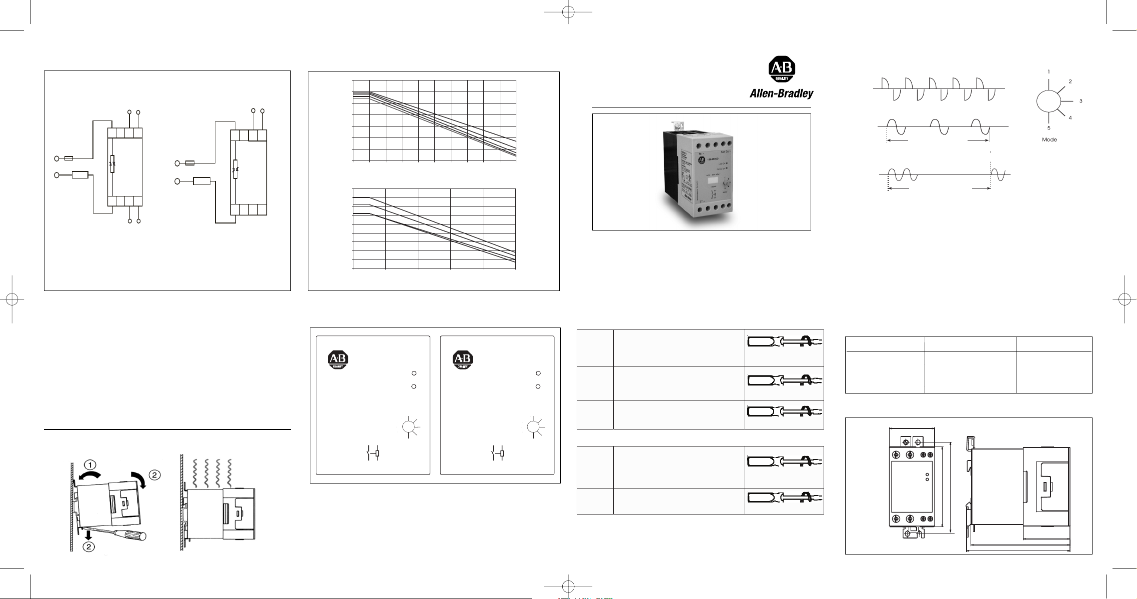
1 period = 64 cycles
1 period = 1s, 3s or 10s
MODE 1
M
ODE 2
MODE 3, 4, 5 - Burst 1s, 3s, 10s
M
ode 1 ( Default): Phase Angle Switching |
Fasevinkel kredsløbskobling |
Phasenanschnittsteuerung | Conexión de
Ángulo de Fase | Commutation de l’angle de
phase | Phase Angle Switching
Mode 2: Distributed Control | Distribueret
kontrol | Vollwellensteuerung | Control
Distribuido | Trains d’ondes distribuées |
Distributed Full Cycle
Mode 3: Burst Switching (1 sec. period) |
Burst kredsløbskobling (1 sek. periode) |
Impulspaketsteuerung (1 s Periodendauer) |
Conexión del tren de pulsos (período de 1 s.)
| Trains d’ondes T.O.R. (période de 1 sec) |
B
urst Switching ( 1 sec. period )
Mode 4: Burst Switching (3 sec. period) |
Burst kredsløbskobling (3 sek. periode) |
Impulspaketsteuerung (3 s Periodendauer) |
Conexión del tren de pulsos (período de 3 s.)
| Trains d’ondes T.O.R. (période de 3 sec) |
Burst Switching ( 3 sec. period )
Mode 5: Burst Switching (10 sec. period) |
Burst kredsløbskobling (10 sek. periode) |
Impulspaketsteuerung (10 s Periodendauer) |
Conexión del trende pulsos (período de 10 s.)
| Trains d’ondes T.O.R. (période de 10 sec) |
Burst Switching ( 10 sec. period )
Note: • For the standard 156-B..V1, it is possible to have the ground terminals of the supply and control commoned externally and
connected to either terminal A2 or A3 only.
This is applicable for a 24V DC supply.
Note: • For standard 156-B..V1, kan man
anvende fælles jordklemmer til både forsyning
og kontrol af strøm. I så fald skal den fælles
jordklemme forbindes til enten klemme A2
eller klemme A3. Dette gælder kun, hvis 24
VDC forsyningsspænding anvendes.
Hinweis: • - Innerhalb des 156-B..V1 können
die Nulleiter der Spannungsversorgung extern
zusammengeführt werden und wahlweise an
den Klemmen A2 und- /oder A3
angeschlossen werden. Diese Möglichkeit ist
nur bei der 24Vdc Spannungsversorgung
möglich.
Note: • Pour la version standard 156-B..V1, il
est possible d'avoir la masse de l'alimentation
et de la commande communes en externe et
raccordée soit à la borne A 2 ou à la borne A
3. Ceci est applicable pour une alimentation
24 VCC.
Nota: • En el modelo estándar 156-B..V1 es
posible tener los terminales del común de la alimentación A2 y del común de control A3 conectadosen el mismocomún de la fuente externade
alimentación, esto sólo se puede hacer cuando
se utiliza una tensión de alimentación de 24 VCC.
Note: • Per il modello standard 156-B..V1, è
possibile avere i terminali di terra, d' alimentazione e di controllo esterni e collegati solo ai
terminali A2 o A3. Questo è applicabile per alimentazioni a 24V CC.
3A1 - 5A3: Control Input Current
Example: 156-B..C1
3A1 - 5A3: Control Input Voltage, Vcc
4A2 - 6A4: Supply Input Voltage, Vss
Example: 156-B..V1
Analog Input
Supply
Analog Input
Connection Examples | Tilslutningseksempler | Anschlussbeispiele
Ejemplos de Conexión | Exemples de raccordement | Esempi di Connessioni
• Operating Instructions
• Kom godt i gang
• Betriebsanleitung
• Notice d'utilisation
• Instrucciones
• Istruzioni d’uso
Dimensions | Dimensioner| Dimensions | Abmessungen | Dimensioni | Dimensiones
45mm
91.6mm
81.7mm
103mm
46.5mm
Mounting | Montering | Montage | Anschlußbeispiel | Montaggio | Montaje
Mode Selection | Overføringsegenskaber | Sélection du Mode | Wahl der
Betriebsart | Selección de Modo | Selezione Commutazione
Transfer Characteristics | Overføringsegenskaber | Caractéristiques de transfert |
Übertragungscharakteristik | Características de Transferencia | Caratteristiche di Trasferimento
Terminal Layout | Terminalfordeling | Exemple de raccordement | Anschlußbeispiel |
Collegamenti Elettrici | Ejemplo de conexión
r
o
tc
atnoCrot
cu
d
n
ocim
eS
Control ON
Load ON
3A1+
5A3-
AC51 : 50A, 600V
~
4-20mA
Mode
1
2
3
4
5
3A1 +1L1
2T1
5A3 -
1L1~
2T1~
156-B50CC1
r
ot
c
a
t
no
Cro
tc
u
d
noci
m
eS
Control ON
Load ON
3A1+
6A4+
5A3-
4A2-
AC51 : 50A, 230V
~
Vss: 24VAC/DC
Vcc: 0-10VDC
Mode
1
2
3
4
5
Vss
Vcc
3A1 +1L1
2T1
5A3 -
1L1~
2T1~
156-B50AV1
D
erating by Spacing | Laststrom in Abhängigkeit vom Geräteabstand | Derating by
Spacing | Curva de reducción | Riduzione delle prestazioni in base alla distanza tra i
d
isposittivi
Load Current (AACrms)Load Current (AACrms)
Surrounding temperature (˚C)
Surrounding temperature (˚C)
20 25 30 35 40 45 50 55 60 65 70
20 30 40 50 60 70
35
30
25
20
15
10
5
0
55
50
45
40
35
30
25
20
15
10
RJ1P...30
RJ1P...50
22.5 mm
22.5/ 10.0 mm
6.0 mm
3.0 mm
0.0 mm
10.0 mm
6
.0 mm
3.0/ 0.0 mm
156-B50..1
156-B30..1
156-B50..I_140509 7680417
Bulletin 156
Single Phase Multi-functional
Analog Switching Solid State Contactor
Control Control Output
Current (mA) Voltage (VDC) Power (%)
400
8 2.5 25
12 5 50
16 7.5 75
20 10 99
Output power as a function of control input
TERMINALS | TERMINALER | TERMINALES | BORNES | ANSCHLÜSSE | TERMINALI
To use 75˚C copper (CU) conductor only. | Brug kun 75˚C kobbel kabler | Use sólo cables de
cobre a 75 ºC | Utiliser seulement des câbles âme cuivre de t° admissible 75°C |
Kupferanschlusskabel für 75°C | Utilizzare 75 ˚ C solo cavi in rame
L1, T1
Ground
Screw
Standard screw M5 x 8mm
(Screw not provided)
Min. 1 x 4mm2(1 x AWG12)
Max. 1 x 25 mm
2
(2 x AWG3)/
2 x10mm2(2 x AWG6)
2.5Nm with Posidrive 2 bit
A1, A2,
A3, A4
Min. 1 x 0.5mm2(1 x AWG20)
Max. 1 x 4mm2(1 x AWG12)/
2 x 2.5 mm2(2 x AWG14)
0.6Nm with Posidrive 0 bit
Max torque 2.5Nm
L1, T1
12 AWG - 3 AWG Str
12 AWG - 10 AWG Sol
2 x 10AWG Sol
2.5Nm with Posidrive 2 bit
A1, A2,
A3, A4
18 AWG - 12 AWG Str and Sol
2 x 14 AWG Str and Sol
0.6Nm with Posidrive 0 bit
IEC
UL
AB_RJ1P(150511).qxd:RJ1P_int3.qxd 5/22/11 11:34 AM Page 2
 Loading...