

Page 1
Medium Voltage
AC Drive
Bulletin 1557
User Manual
Page 2
Important User Information
IMPORTANT
Read this document and the documents listed in the Additional Resources section about installation, configuration, and
operation of this equipment before you install, configure, operate, or maintain this product. Users are required to
familiarize themselves with installation and wiring instructions in addition to requirements of all applicable codes, laws,
and standards.
Activities including installation, adjustments, putting into service, use, assembly, disassembly, and maintenance are required
to be carried out by suitably trained personnel in accordance with applicable code of practice.
If this equipment is used in a manner not specified by the manufacturer, the protection provided by the equipment may be
impaired.
In no event will Rockwell Automation, Inc. be responsible or liable for indirect or consequential damages resulting from the
use or application of this equipment.
The examples and diagrams in this manual are included solely for illustrative purposes. Because of the many variables and
requirements associated with any particular installation, Rockwell Automation, Inc. cannot assume responsibility or
liability for actual use based on the examples and diagrams.
No patent liability is assumed by Rockwell Automation, Inc. with respect to use of information, circuits, equipment, or
software described in this manual.
Reproduction of the contents of this manual, in whole or in part, without written permission of Rockwell Automation,
Inc., is prohibited.
Throughout this manual, when necessary, we use notes to make you aware of safety considerations.
WARNING: Identifies information about practices or circumstances that can cause an explosion in a hazardous environment,
which may lead to personal injury or death, property damage, or economic loss.
ATTENTION: Identifies information about practices or circumstances that can lead to personal injury or death, property
damage, or economic loss. Attentions help you identify a hazard, avoid a hazard, and recognize the consequence.
Identifies information that is critical for successful application and understanding of the product.
Labels may also be on or inside the equipment to provide specific precautions.
SHOCK HAZARD: Labels may be on or inside the equipment, for example, a drive or motor, to alert people that dangerous
voltage may be present.
BURN HAZARD: Labels may be on or inside the equipment, for example, a drive or motor, to alert people that surfaces may
reach dangerous temperatures.
ARC FLASH HAZARD: Labels may be on or inside the equipment, for example, a motor control center, to alert people to
potential Arc Flash. Arc Flash will cause severe injury or death. Wear proper Personal Protective Equipment (PPE). Follow ALL
Regulatory requirements for safe work practices and for Personal Protective Equipment (PPE).
Allen-Bradley, Rockwell Software, Rockwell Automation, and TechConnect are trademarks of Rockwell Automation, Inc.
Trademarks not belonging to Rockwell Automation are property of their respective companies.
Page 3

TABLE OF CONTENTS
Chapter 1 .......................................................... Using This Manual
Chapter 2 ......................................................... Introduction
Chapter 3 .......................................................... Specifications
Chapter 4 .......................................................... Hardware Description
Chapter 5 .......................................................... Description of Operation
Chapter 6 .......................................................... Parameter and Variable
Descriptions
Chapter 7 .......................................................... Operator Interface Terminal
Chapter 8 .......................................................... Installation
Chapter 9 .......................................................... Commissioning
Chapter 10 ........................................................ Troubleshooting
Chapter 11 ........................................................ Spare Parts
1557-UM050F-EN-P – June 2013
Page 4

1557-UM050F-EN-P – June 2013
Page 5
USING THIS MANUAL 1-1
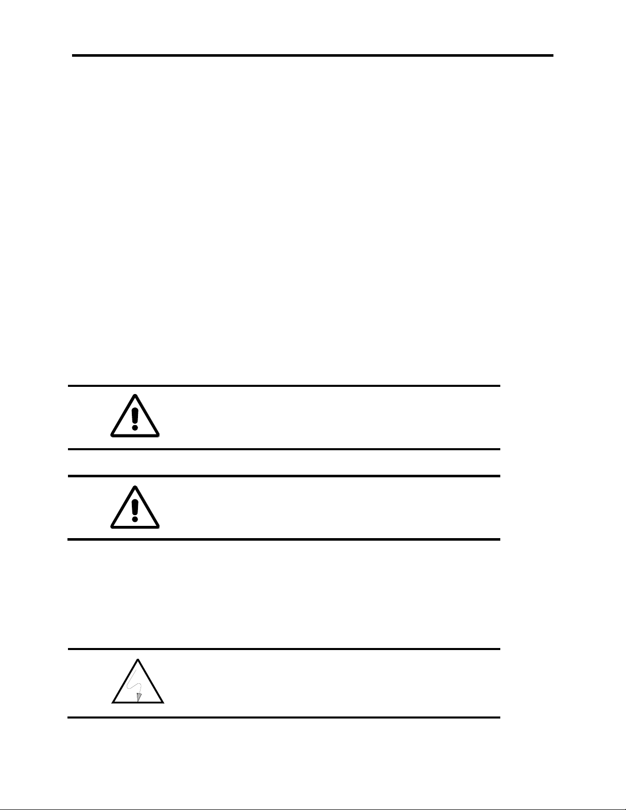
Warnings tell readers where people may be hurt if
procedures are not followed properly.
Cautions tell readers where machinery may be damaged
or economic loss can occur if procedures are not
followed properly.
This symbol alerts the user to a potential electrical shock
hazard which exists on a component or printed circuit
board.
Manual Objectives
This manual is intended for use by personnel familiar with Medium Voltage and variable speed solid-state
drive equipment. The manual contains material which will allow the user to operate, maintain, and
troubleshoot the drive system.
IMPORTANT USER INFORMATION
Because of the variety of uses for this equipment and because of the differences between this solid-state
equipment and electromechanical equipment, the user of and those responsible for applying this
equipment must satisfy themselves as to the acceptability of each application and use of the equipment.
In no event will Rockwell Automation be responsible or liable for indirect or consequential damages
resulting from the use or modification of this equipment.
The illustrations shown in this manual are intended solely to illustrate the text of this manual Because of
the many variables and requirements associated with any particular installation, Rockwell Automation
cannot assume responsibility or liability for actual use based upon the illustrative uses and applications.
No patent liability is assumed by Rockwell Automation with respect to use of information, circuits,
equipment or software described in this text.
Reproduction of the content of this manual, in whole or in part, without written permission of Rockwell
Automation is prohibited.
Both of these:
• Identify a possible trouble spot.
• Tell what causes the trouble.
• Give the result of improper action.
• Tell the reader how to avoid trouble.
1557-UM050F-EN-P – June 2013
Page 6

1-2 USING THIS MANUAL
REPAIR OR REPAIR/EXCHANGE PROCEDURE
For your convenience, Rockwell Automation and Rockwell Automation Global Technical Services(GTS),
provide an efficient and convenient method of returning equipment eligible for repair or repair/exchange.
A Product Service Report (P.S.R.) number is required to return any equipment for repair. This may be
obtained from your area Rockwell Automation Distributor, Sales Office or Area Support Division.
Return any equipment to be repaired to the Area Support Division nearest you. Be sure to reference the
P.S.R. number on the carton and packing slip. Include your company name and address, your repair
purchase order number, and a brief description of the problem. This will facilitate quick return of your
equipment.
A complete listing of Global Technical Services offices may be obtained by calling your area Rockwell
Automation Distributor or Sales Office.
1557-UM050F-EN-P – June 2013
Page 7

INTRODUCTION CHAPTER 2
The Bulletin 1557 drive is a Pulse Width Modulated Current Source Machine side converter (PWM - CSI).
It is designed to supply 3 phase currents to standard induction motor loads. The Bul. 1557 MV (medium
voltage) drive converts 3 phase 50/60 Hz input power to an adjustable AC frequency current source for
speed control of AC squirrel cage motors.
The solid state technology used in the design is of proven reliability. A number of circuit implementation
techniques used are unique to the Allen-Bradley Bulletin 1557 drive.
The basic design philosophy emphasizes the isolation of single component failures, such that multiple
component failures do not occur. This leads to a low MTTR, (Mean Time To Repair), with extensive fault
diagnostic circuits and easy accessibility.
The basic design features of the Allen-Bradley Bulletin 1557 drive are as follows:
The three phase motor currents are sinusoidal with low total harmonic distortion.
The design uses isolated driver circuits, one per gate turn off thyristor (GTO), and
silicon controlled line side converter (SCR).
Two output phases are individually current sensed, ensuring protection and control.
The design is capable of producing smooth low speed torque with low harmonic current
to the motor.
A fuseless electronic protection scheme is used in the power circuit for normal fault
conditions. Power fuses provide back up protection and ensure safety.
Heatsinks are monitored with temperature sensors to detect overtemperatures.
(BUL 1557 Air-cooled units only)
The 1557 Drive uses a North American design base with all components readily
accessible from the front without need to extensively dismantle the unit.
The drive system logic is microcomputer based, thus eliminating numerous trimpots
for system calibration.
Fault and alarm indication is performed using an operator interface panel.
1557-UM050F-EN-P – June 2013
Page 8

2-2 INTRODUCTION
An Input contactor with fused isolating switch is optional on the 1557 drive and is only supplied
when specified or if the customer does not have an existing full voltage starter.
The standard 1557 drive is a tachless design. A tachometer is recommended for applications
requiring an output frequency lower than 6 hertz or applications with a starting torque greater than
30%.
A drive isolation transformer or AC line reactor is required with each drive. An isolation
transformer is mandatory when existing motors are used, 12-Pulse line side converters are used,
or for stepping down the main supply voltage. An AC line reactor may only be used when new
motors are used with the proper level of phase to ground insulation. Consult your Rockwell
Automation representative for more information.
1557-UM050F-EN-P – June 2013
Page 9

SPECIFICATIONS CHAPTER 3
The electrical and environmental specifications of the Bulletin 1557 MV Drive are provided below:
Input Voltages: 2300Vac ± 10%, 3-Phase
3300Vac ± 10%, 3-Phase
4160Vac ± 10%, 3-Phase
6900Vac ± 10%, 3-Phase
Input Frequency: 50/60Hz ± 3Hz
Efficiency: 97% at full load (minimum)
Output Voltage: 0 to 2300Vac, 3-Phase
0 to 3300Vac, 3-Phase
0 to 4160Vac, 3-Phase
0 to 6900Vac, 3-Phase
Output Frequency: 6Hz to 75Hz (Without Tach)
0.2Hz to 75 Hz (With Tach)
Speed Regulation: 0.5% of maximum speed (Without Tach)
0.1% of maximum speed (With Tach)
Speed Reference: 0 to 10V dc or
4 to 20 mA dc
Operating Temperature: Ambient temperature must be within the range of 0° to 40°C
with a relative humidity of up to 95% (non-condensing)
Storage Temperature: Ambient temperature must be within the range of –40° to 70°C
Altitude: No derating below 1000 m above sea level
1557-UM050F-EN-P – June 2013
Page 10

3-2 SPECIFICATIONS
1557-UM050F-EN-P – June 2013
Page 11
HARDWARE DESCRIPTION 4-1
Hardware Overview
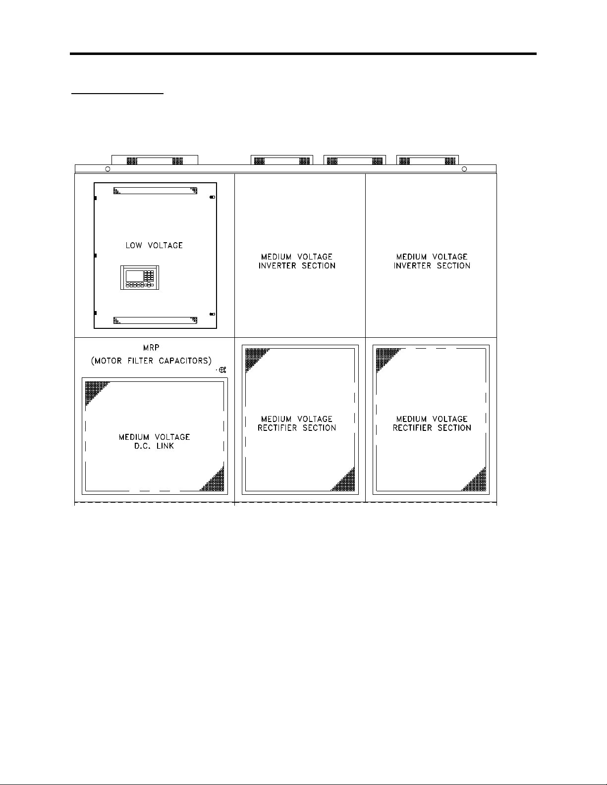
The basic drive consists of two cabinets; the D.C. link/control cabinet and the converter cabinet. An input
contactor cabinet is optional. (See Figure 4.1)
Figure 4.1 – Outline of 1557 Drive
1557-UM050F-EN-P – June 2013
Page 12
4-2 HARDWARE DESCRIPTION
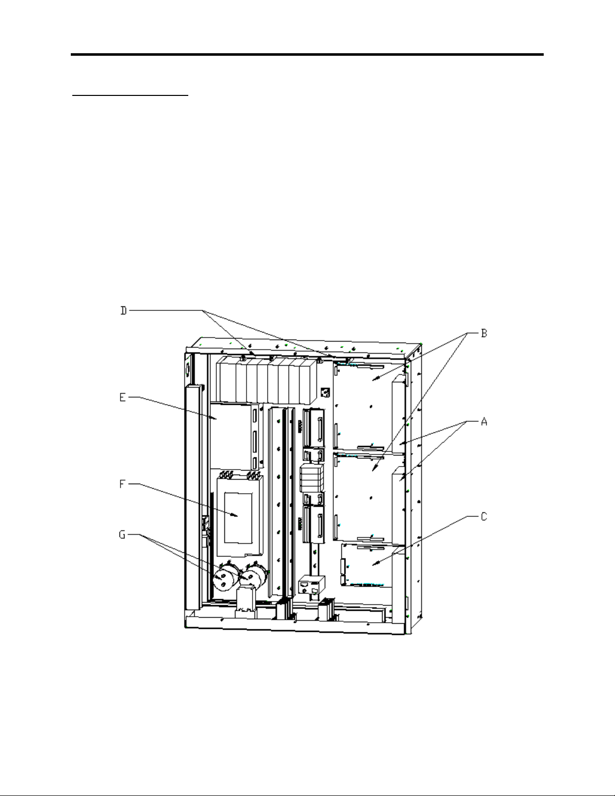
DC Link Control Cabinet
The D.C. link/control cabinet is 44 inches wide. The top section has a panel with operator interface
devices mounted on a door within a door. A fully vented door is in the bottom position.
Access to the low voltage control compartment is gained through the hinged low voltage panel.
All low voltage compartments contain the following elements:
4.2 (A) Fiber optic interface boards ( 2 )
4.2 (B) Drive control boards ( 2 for 6-pulse, 3 for 12-pulse )
4.2 (C) Communication processor board ( 1 )
4.2 (D) Digital I/O boards ( 2 )
4.2 (E) D.C./D.C. converter ( 1 )
4.2 (F) A.C./D.C. power supply ( 1 )
4.2 (G) Capacitors
See Figure 4.2
Figure 4.2 – Typical Low Voltage Compartment
1557-UM050F-EN-P – June 2013
Page 13
HARDWARE DESCRIPTION 4-3
Warning: Allow 5-10 minutes for motor filter capacitors to
safely discharge voltage prior to opening cabinet doors.
D.C. Link Reactor
The D.C. link reactor is floor mounted and may be shipped separately and installed on site in larger drives.
Motor Filter Capacitors
Located behind the low voltage compartment, the motor filter capacitors are accessible when the upper
medium voltage door is opened. There are 3 capacitors for low horsepower drives and 6 for larger drives.
The capacitors are liquid filled and mounted on rails. The metal cases of the capacitors are grounded to
the cabinet.
1557-UM050F-EN-P – June 2013
Page 14
4-4 HARDWARE DESCRIPTION
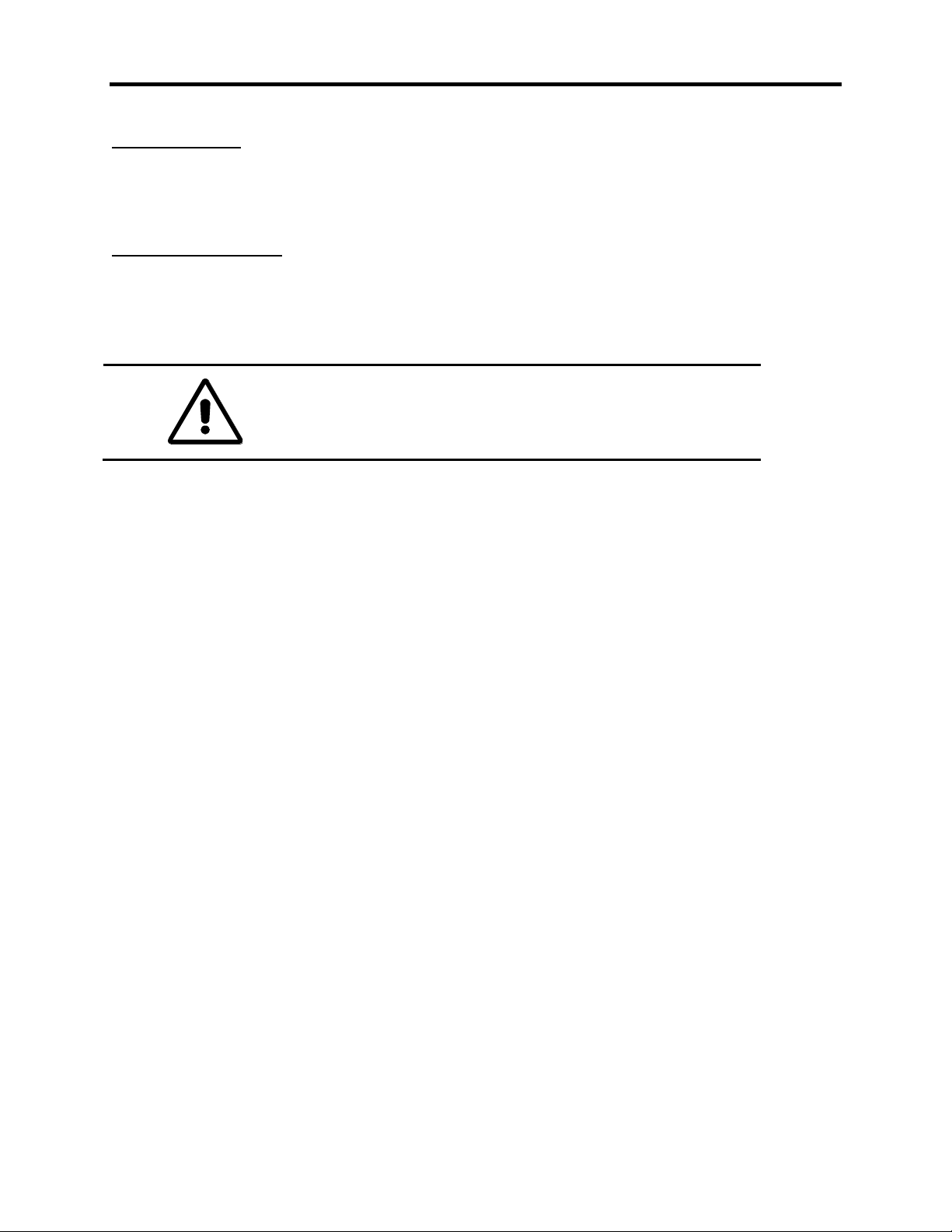
4.3(A)
4.3(D)
4.3(F)
4.3(B)
4.3(C)
4.3(E)
Line side converter Components
The line side converter is located in the lower half of the converter cabinet. The line side converter
consists of three identical cells; each cell consists of the following:
4.3 (A) -line side converter heatsink stack
-Silicon Controlled Line side converter (SCR) thyristors
-heatsinks
-clamp
4.3 (B) -snubber capacitors
4.3 (C) -snubber resistors
4.3 (D) -voltage sharing/diagnostic resistors
4.3 (E) -gate driver circuit boards
4.3 (F) -power supply boards
(See Figure 4.3 )
Figure 4.3 – Line Side Converter Components
(2300 V Line Side Converter shown)
1557-UM050F-EN-P – June 2013
Page 15
HARDWARE DESCRIPTION 4-5
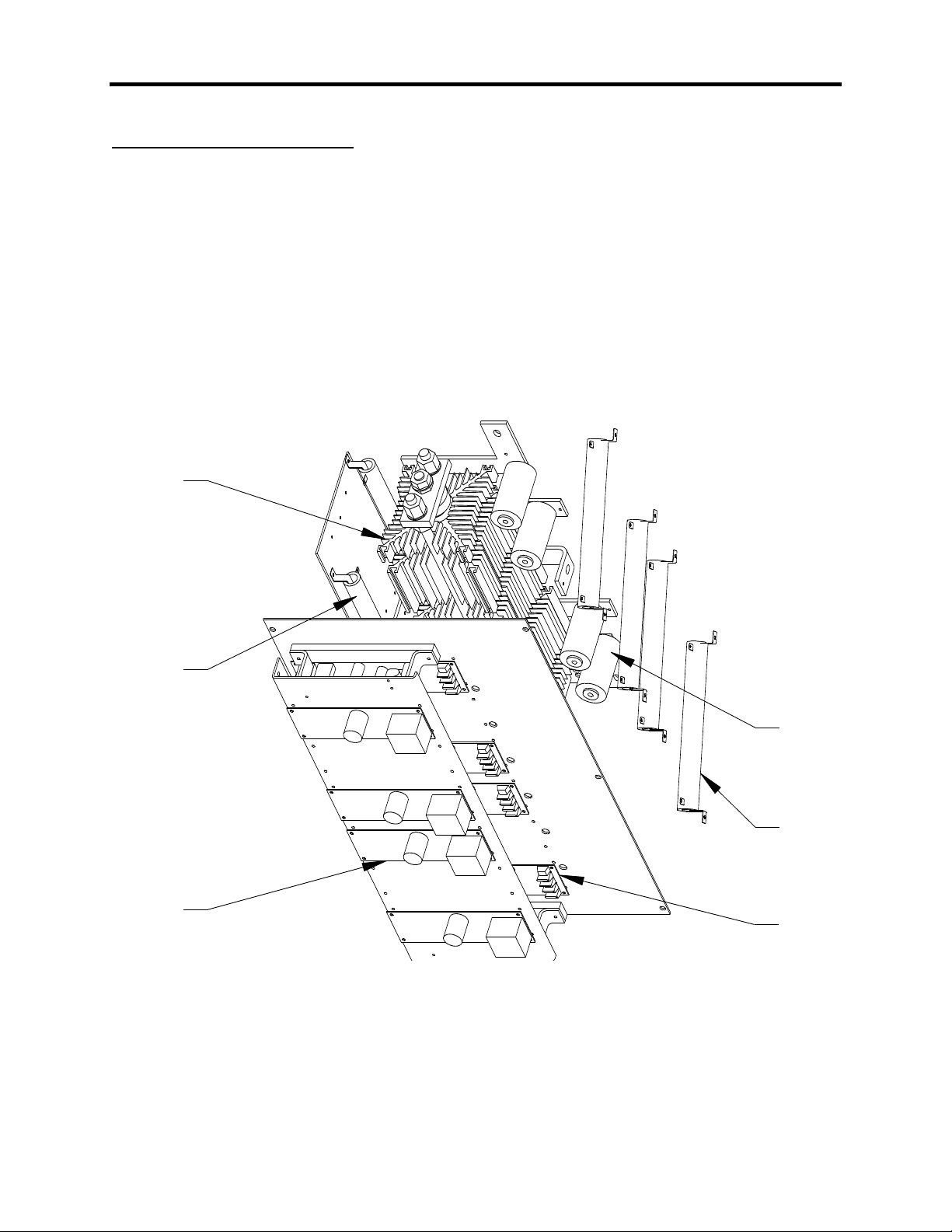
4.4(A)
4.4(E)
4.4(D)
4.4(G)
4.4(C)
4.4(D)
4.4(B)
4.4(F)
Machine side converter Components
The machine side converter is located in the upper half of the converter cabinet. The machine side
converter consists of three identical cells. each cell consists of the following:
4.4 (A) -machine side converter heatsink stack assemblies
-Gate Turn Off (GTO) thyristors
-heatsinks
-clamp
4.4 (B) -snubber resistors
4.4 (C) -snubber capacitors
4.4 (D) -snubber diode assemblies
- Fast recovery diode
- diode clamp
-snubber capacitors for the snubber diodes
-snubber resistors for the snubber diodes
4.4 (E) -voltage sharing/diagnostic resistors
4.4 (F) -gate driver circuit boards
4.4 (G) -power supply boards
(See Figure 4.4 )
Figure 4.4 – Machine Side Converter Components
(2300 V Machine Side Converter shown)
Three of the machine side converter heatsink assemblies (one in each phase) have thermistors mounted
on the heatsinks, each thermistors is wired to a small circuit board (Thermistor Feedback board) which is
located near the gate driver boards. In the event of heatsink overtemperature, a fault signal is sent to the
controller and the drive will shut down.
1557-UM050F-EN-P – June 2013
Page 16

4-6 HARDWARE DESCRIPTION
Voltage Feedback Circuit Boards
Voltage feedback boards are located in the converter cabinet on the far left side mounted on a vertical
glass polyester channel. The boards consist of series connected resistors for sensing input voltage, DC
link voltage, and output voltage.
Cooling Fans
There are several different arrangements of cooling fans. Fans are required to remove heat from the drive
to ensure proper operation of its components. The fans draw air into the drive through the vented lower
doors and exhaust it through vented enclosures at the top of the drive.
1557-UM050F-EN-P – June 2013
Page 17

DESCRIPTION OF OPERATION CHAPTER 5
Introduction ......................................................................................................................... 1
Speed Command ................................................................................................................ 3
Skip Speeds ........................................................................................................................ 5
Speed Ramp ....................................................................................................................... 7
Speed Control ..................................................................................................................... 9
Flux Control ....................................................................................................................... 11
Flux Control for Synchronous Motor .................................................................... 13
Current Control .................................................................................................................. 14
Line Converter Feedback .................................................................................................. 16
Machine Converter Feedback ........................................................................................... 18
Motor Model ...................................................................................................................... 20
Line Converter Protection ................................................................................................. 22
Machine Converter Protection .......................................................................................... 24
Analog Outputs ................................................................................................................. 26
Test Modes ....................................................................................................................... 28
Synchronous Transfer ....................................................................................................... 29
Transfer To Bypass ........................................................................................................... 30
Transfer To Drive .............................................................................................................. 31
Thyristor Diagnostics
Bulletin 1557 Drive ............................................................................................... 33
Bulletin 1557M Mini Drive .................................................................................... 35
Flying Start ................................................................................................................ 36
Tachometer/Encoder Option ............................................................................................. 37
1557-UM050F-EN-P –June 2013
Page 18

1557-UM050F-EN-P – June 2013
Page 19

DESCRIPTION OF OPERATION 5-1
Introduction
The Bulletin 1557 is an adjustable speed ac drive in which motor speed control is achieved through
control of the motor torque. The motor speed is measured and the torque is adjusted as required to make
the measured speed equal to the speed command. The stator frequency is determined by the motor and
load and the drive synchronizes itself to the motor. This is in contrast to the more common volts/hertz ac
drive in which the drive determines the stator frequency and does not attempt to synchronize its output to
the motor.
The method of control used is known as direct vector control. The term vector control indicates that the
position of the stator current vector is controlled relative to the motor flux vector. Direct vector control
means that the motor flux is measured, in contrast to the more common indirect vector control in which
the motor flux is predicted. In both cases, the stator current is resolved into flux producing and torque
producing components which are controlled independently. The intent is to achieve performance similar
to a dc machine, in which the torque can be changed quickly without affecting the flux. The flux cannot
be changed quickly because of the rotor time constant, which is in the range of seconds for large
machines.
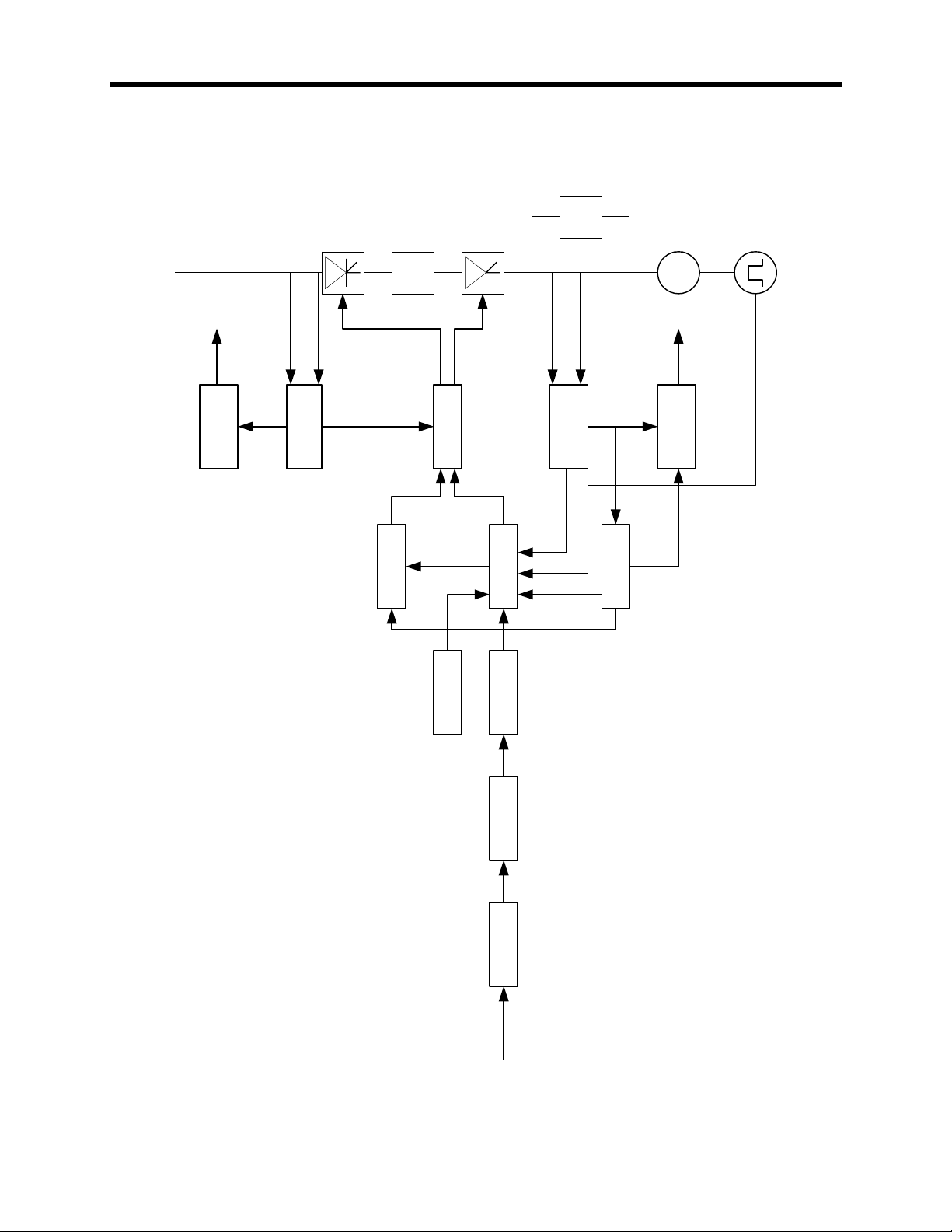
The following description of operation is organized in the same functional blocks as the control block
diagram (Figure 5.1). Most of the functions are the same as those found in any adjustable speed ac or dc
drive. The features which are unique to a direct vector controlled drive are confined to the motor model
and flux control functions.
The Bulletin 1557 drive can be used with either induction (asynchronous) or synchronous motors.
Synchronous motor drives are identical to induction motor drives except for the addition of a current
regulated field supply to the synchronous drive. The features that are unique to a synchronous drive are
confined to the flux control function and the encoder option.
1557-UM050F-EN-P –June 2013
Page 20
5-2 DESCRIPTION OF OPERATION
SPEED
COMMAND
SPEED
RAMP
SPEED
CONTROL
MOTOR
MODEL
LINE
CONVERTER
FEEDBACK
CURRENT
CONTROL
FLUX
CONTROL
SKIP
SPEEDS
LINE
CONVERTER
PROTECTION
MACHINE
CONVERTER
PROTECTION
MACHINE
CONVERTER
FEEDBACK
SYNCHRONOUS
TRANSFER
Flux
Feedback
Slip
Speed
Magnetizin
g Current
Command
Torque
Current
Comand
Stator
Frequency
Tach
Feedback
MOTOR
Faults
Voltage
Feedback
Current
Feedback
DC
Link
Motor Filter
Capacitor
Faults
Voltage
Feedback
Current
Feedback
Line
Converter
Machine
Converter
Line
Converter
Firing Angle
Machine
Converter
Firing Angle
(Pxxx) Indicates a read/write parameter with a linear number of xxx.
(Vxxx) Indicates a read only variable with a linear number of xxx.
Speed
Commands
Figure 5.1
1557-UM050F-EN-P – June 2013
Page 21

DESCRIPTION OF OPERATION 5-3
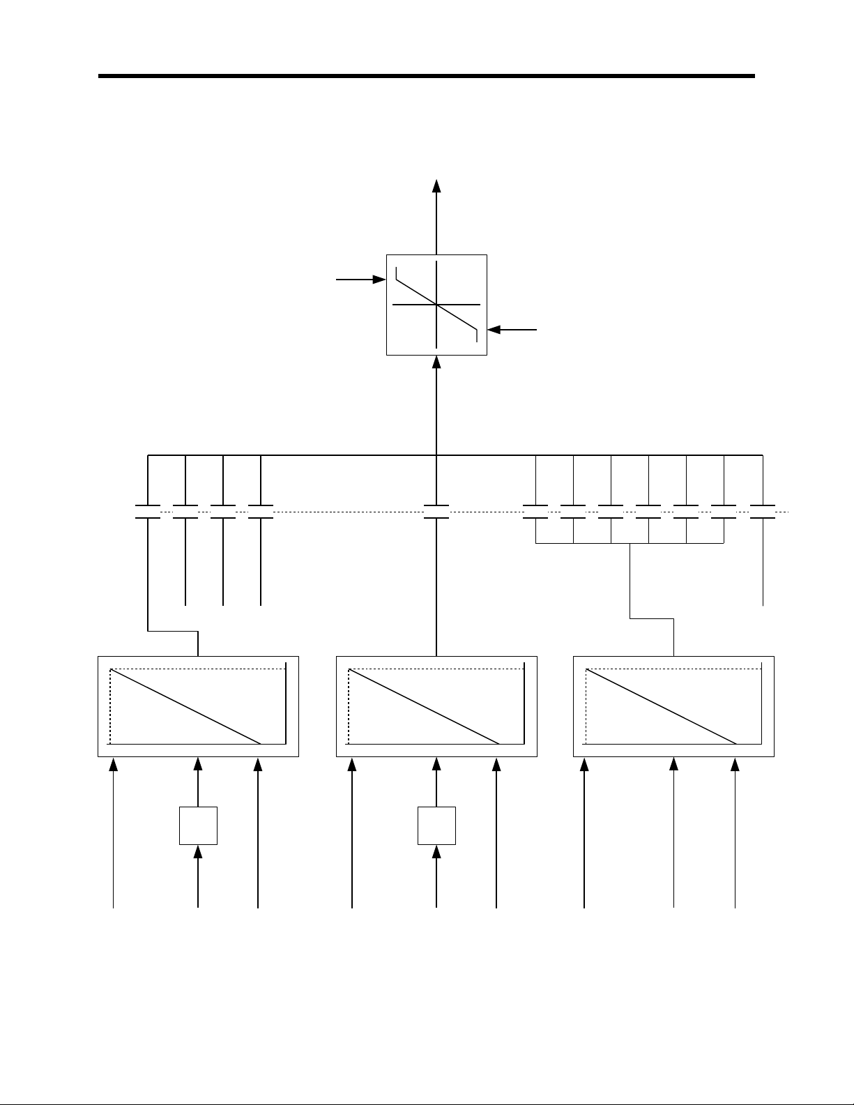
Speed Command
The function of the speed command block is to select one of 12 possible speed command inputs to serve
as the drive speed command. Bits 12-15 of the Logic Command are used to select the Speed Command
Input from the following list:
2 analog inputs (0-10V)
3 preset speed commands
6 SCANbus ports
1 preset jog speed command
The two analog speed command inputs accept 0-10V signals. The range of each of the analog inputs is
defined by two parameters. These parameters can be adjusted to cause the speed command to either
increase or decrease with an increasing analog input.
The six SCANport ports are multiplexed into a single SCANport input. The range of the digital input is
defined by two parameters in the same way as the analog inputs.
The selected speed command input is clamped to a minimum level set by parameter Speed Command
Minimum and a maximum level set by parameter Speed Command Maximum. (See Parameter and
Variable Description in Chapter 6.)
1557-UM050F-EN-P –June 2013
Page 22
5-4 DESCRIPTION OF OPERATION
0V 10V
A/D
Speed cmd 0 max (P42)
Speed cmd 0 min (P41)
Analog
input 1L
(V353)
Line
AI1
ANALOG SPEED
COMMAND INPUT
0V 10V
A/D
Speed cmd 8 max (P44)
Speed cmd 8 min (P43)
Analog
input 1M
(V355)
Machine
AI1
ANALOG SPEED
COMMAND INPUT
0 32767
Speed cmd 9 max (P46)
Speed cmd 9 min (P45)
DIGITAL SPEED
COMMAND INPUT
SCANport input (V398)
Speed command 0
(V273)
0000 (0)
Preset speed 1
(P33)
0001 (1)
Preset speed 2
(P34)
0010 (2)
Preset speed 3
(P35)
0011 (3)
Speed command 8
(V274)
1000 (8)
1001 (9)
1010 (10)
1011 (11)
1100 (12)
1101 (13)
1110 (14)
Preset jog speed
(P40)
1111 (15)
Speed Command in
(V276)
Speed command 9
(V275)
Speed cmd max
(P48)
Speed cmd min
(P47)
to skip speed
processing
Logic command bits 12 - 15 (spd cmd select)
(V258)
Speed Command
1557-UM050F-EN-P – June 2013
Page 23

DESCRIPTION OF OPERATION 5-5
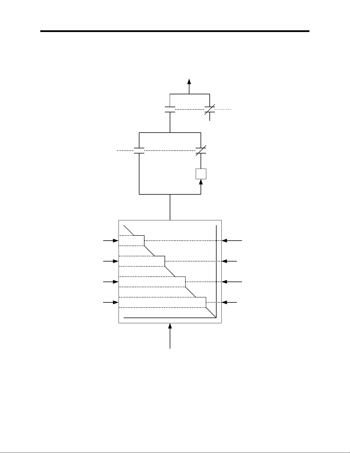
Skip Speeds
Four skip speeds are provided which may be used to prevent the drive from continuously operating at
certain speeds, usually to avoid exciting mechanical resonance. Each of the four skip speed zones is
defined by two parameters that specify its center point and width. Skip speed zones that overlap are
merged.
After skip speed processing, the speed command input has its sign changed if reverse rotation is
selected, or is set to zero if there is no run request.
1557-UM050F-EN-P –June 2013
Page 24
5-6 DESCRIPTION OF OPERATION
Skip speed 1
(P49)
Skip speed 2
(P50)
Skip speed 4
(P52)
Skip speed 3
(P51)
Skip speed
band 1
(P53)
Skip speed
band 2
(P54)
Skip speed
band 3
(P55)
Skip speed
band 4
(P56)
from speed
command limit
-1
Speed command
(V277)
0
Logic status bit 1 (V258)
(Running)
Logic status bit 2 (V258)
(Forward command)
Skip Speeds
1557-UM050F-EN-P – June 2013
Page 25

DESCRIPTION OF OPERATION 5-7
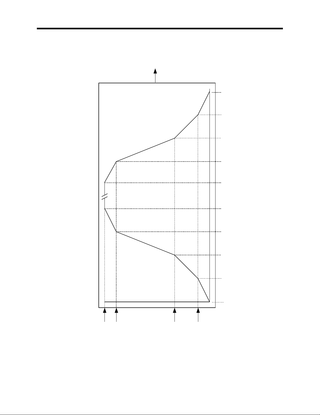
Speed Ramp
The function of the speed ramp is to control the rate of change of the drive speed reference. Independent
four section ramps are provided for acceleration and deceleration. Each ramp is defined by four speed
points which are specified by parameters Ramp Speed 1 to 4 which are the same for both accelerating
and decelerating, and four time intervals which are specified by parameters Acceleration Time 1 to 4 and
Deceleration Time 1 to 4. The input to the speed ramp is the speed command from the skip speed block.
The drive control selects the appropriate acceleration or deceleration rate based on the present value of
the ramp output and whether it is increasing or decreasing. The output of the speed ramp is the speed
reference, which is the input to the speed control block. If the motor is coasting and speed feedback is
available, the speed reference is set equal to the motor speed.
1557-UM050F-EN-P –June 2013
Page 26
5-8 DESCRIPTION OF OPERATION
Accel
time 1
(P65)
Accel
time 2
(P66)
Accel
time 3
(P67)
Accel
time 4
(P68)
Decel
time 4
(P65)
Decel
time 3
(P66)
Decel
time 2
(P67)
Decel
time 1
(P68)
Ramp speed 3
(P75)
Ramp speed 2
(P74)
Ramp speed 1
(P73)
Ramp speed 4
(P76)
Speed
Reference
(V278)
Speed Ramp
1557-UM050F-EN-P – June 2013
Page 27

DESCRIPTION OF OPERATION 5-9
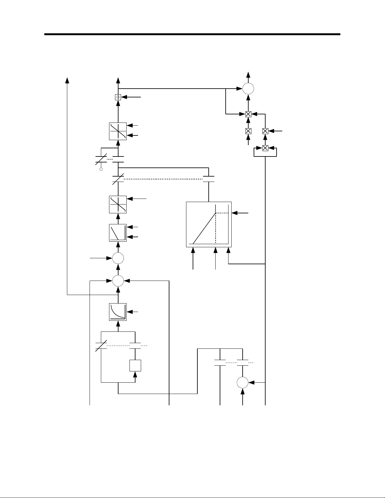
Speed Control
The function of the speed control block is to determine the torque current command. The inputs are the
speed reference from the speed ramp, and the stator frequency and slip frequency from the motor model.
Either tach feedback is used, or the slip frequency is subtracted from the stator frequency to determine
the motor speed, which is then made negative if the motor is rotating in reverse. The result is filtered by
an adjustable second order low pass filter to obtain the drive speed feedback.
The speed feedback is subtracted from the speed reference to determine the speed error. Parameter
Speed Reference Step, which is used to demonstrate the step response of the speed loop, is added to
the speed error to form the input to the speed regulator. The response of the speed regulator is
determined by parameters Speed Regulator Bandwidth and Total Inertia. The rate of change of the
speed regulator output is limited to the value specified by parameter Torque Rate Limit. The output of the
speed regulator is clamped to the value specified by parameter Torque Limit Motoring for positive values
and to the value specified by parameter Torque Limit Braking for negative values. The clamped output of
the speed regulator is the torque reference. This is divided by the flux reference to determine Isq
Command, which is the torque component of the stator current command.
Without a tachometer, reliable speed feedback is not available at stator frequencies below about 5 Hz.
The speed regulator is therefore disabled at low speed and the torque reference is determined by open
loop programming. The torque reference changes linearly from the value specified by parameter Torque
Command 0 at zero speed to the value specified by parameter Torque Command 1 at Ramp Speed 1,
and remains constant above this speed if the drive is still in start mode. When tach feedback is enabled
the open loop torque programming is not used.
An estimate of the torque producing current supplied by the motor filter capacitor is calculated from Isq
Command, stator frequency, and parameters Total Leakage Inductance and Filter Capacitor. The
resulting value is called Icq Command and is subtracted from Isq Command to determine Iy Command,
which is the torque component of the dc link current command.
1557-UM050F-EN-P –June 2013
Page 28
5-10 DESCRIPTION OF OPERATION
Tach
feedback
(V348)
Slip
frequency
(V343)
Stator
frequency
(V337)
Speed Feedback Mode
(P89)
-
-1
Logic status bit 3 (V258)
(Forward rotation)
SPEED
FEEDBACK
FILTER
Speed fdbk filter
(P110)
Speed
reference
(V278)
from
sync
transfer
Sync spdref
SPEED
REGULATOR
RATE
LIMIT
TORQUE
LIMITING
Trq command 0
(P86)
Trq command 1
(P87)
Ramp speed 1
(P73)
Speed ref step (P88)
-
Speed
error
(V290)
Spdreg
bandwidth
(P81)
Total
Inertia
(P82)
Trq rate
limit (P83)
Start mode
STARTING TORQUE
PROGRAMMING
1
0
Trq limit
motoring
(P84)
Trq limit
braking
(P85)
Filter capacitor
(P133)
SPEED CONTROL
L Total
leakage
(P130)
Icq
command
(V293)
-
Flux
reference
(V305)
Logic Status Bit (V258)
(Running)
Speed
Feedback
(V289)
ISQ
Command
(V292)
IY
Command
(V294)
Torque
Reference
(V291)
Speed Control
1557-UM050F-EN-P – June 2013
Page 29

DESCRIPTION OF OPERATION 5-11
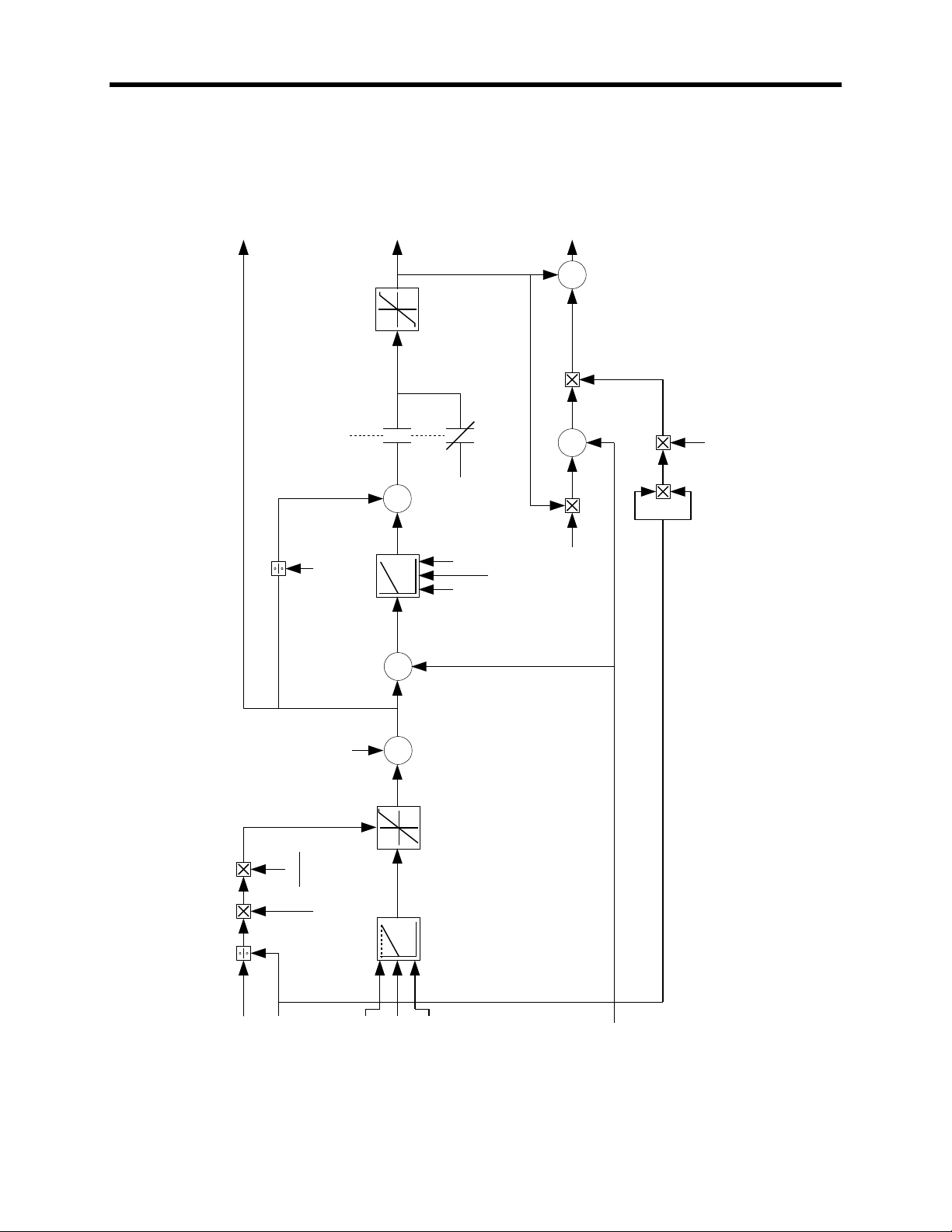
Flux Control
The function of the flux control block is to determine the magnetizing current command. The inputs are
flux feedback and stator frequency from the motor model, speed feedback from the speed control block,
and line voltage from the current control block.
Below base speed, the flux command varies linearly with Torque Reference from the value specified by
parameter Flux Command No Load at zero torque to the value specified by parameter Flux Command
Base Speed at rated torque. Above base speed, the drive goes into field weakening and the flux
command decreases with increasing speed. The flux command also decreases when the current
regulator approaches advance limit or retard limit.
The flux reference is determined by adding parameter Flux Reference Step, which is used to demonstrate
the step response of the flux regulator, to the flux command. The flux feedback is subtracted from the
flux reference to determine the flux error, which is the input to the flux regulator. The response of the flux
regulator is determined by parameters Flux Regulator Bandwidth, Magnetizing Inductance, and Rotor
Time Constant. The output of the flux regulator is called Isd Command 1. An open loop estimate of the
magnetizing current called Isd Command 0 is determined by dividing the flux reference by parameter
Magnetizing Inductance. Isd Command 0 and Isd Command 1 are added to produce Isd Command,
which is the magnetizing component of the stator current command.
An estimate of the magnetizing current supplied by the motor filter capacitor is calculated from Isd
Command, stator frequency, and parameters Total Leakage Inductance and Filter Capacitor. The
resulting value is called Icd Command and is subtracted from Isd Command to determine Ix Command,
which is the magnetizing component of the dc link current command. Ix Command becomes negative at
high speed because the motor filter capacitor supplies more magnetizing current than the motor requires.
1557-UM050F-EN-P –June 2013
Page 30
5-12 DESCRIPTION OF OPERATION
V line
(V324)
Speed feedback
(V289)
Base Speed
(P98)
Lm
Lm+2Ls'
Flx ref
step
(P102)
L magnetizing
(P131)
Isd command 0 (V308)
Isd
command 1
(V309)
Flux
reference
(V305)
Logic status
bit 1 (V258)
(Running)
Isd
command
(V310)
1.0
-1.0
0
-
Flx cmd
base spd
(P100)
Flx cmd
no load
(P103)
Torque
reference
(V291)
Flux
feedback
(V306)
FLUX COMMAND
PROGRAMMING
FLUX
LIMITING
Flux error
(V307)
FLUX
REGULATOR
Flxreg
bandwidth
(P97)
L magnetizing
(P131)
T rotor
(P132)
EXCITATION
CURRENT
LIMITING
L total
leakage
(P130)
Icd
command
(V311)
-
Ix
Command
(V312)
Filter
capacitor
(P133)
Flux Control
1557-UM050F-EN-P – June 2013
Page 31

DESCRIPTION OF OPERATION 5-13
-
Icd command
gain (P105)
Icd command
(V311)
Isd command
(V310)
If cmd bandwidth
(P104)
LOW PASS
L magnetizing
(p131)
Lmd
(P135)
Ix
command
(V312)
I field
command
(V314)
+++
+ -
Flux Control for Synchronous Motor
Flux Control for Synchronous Motor
Most of the magnetization for a synchronous motor is supplied by the rotor field winding, unlike an
induction motor where all of the magnetizing current is supplied through the stator. However, control of
the motor flux through the field current is very slow because of the large time constant of the dc field
winding and the current and voltage limitations of the field supply. To obtain sufficiently fast response
from the flux regulator the magnetizing current is split into transient and steady state components, with
the steady state component supplied through the rotor and the transient component through the stator.
The additions to the flux control required for synchronous machines are shown in the block diagram
below. A low pass filter controlled by parameter If Cmd Bandwidth is used to extract the steady state
component of Isd Command which becomes I Field Command, the current reference for the field supply.
The transient component of Isd Command is obtained by subtracting I Field Command from the original
Isd Command and multiplying by the ratio of L magnetizing to Lmd to provide the same gain for the
steady state and transient components. The portion of the motor filter capacitor current supplied by the
drive is then added to determine Ix Command, which is the magnetizing component of the dc link current
command.
Parameter Icd Command Gain determines how the motor filter capacitor current is split between the
motor and the drive. When this parameter is set to its minimum value of 0.0, all the capacitor current is
supplied by the drive. The line current is higher than the motor current and the motor operates at
approximately unity power factor. When this parameter is set to its maximum value of 1.0, all the
capacitor current is supplied by the motor. The line current is less than the motor current and the motor
operates at a lagging power factor with reduced field current. Increasing Icd Command Gain improves
the input power factor of the drive, but also increases the coupling between flux and torque and causes
the stability of the flux control to deteriorate.
1557-UM050F-EN-P –June 2013
Page 32

5-14 DESCRIPTION OF OPERATION
Current Control
The function of the current control block is to determine the firing angles of the line and machine
converters. The inputs are the torque and flux producing components of the dc link current command
from the speed control and flux control blocks respectively, and the dc link current and line voltage from
the line converter feedback.
The square root of the sum of the squares of Ix Command and Iy Command is calculated to determine
the dc link current command. In dc current test mode, parameter DC Current Test Command is used as
the dc link current command. Parameter DC Current Reference Step, which is used to demonstrate the
step response of the current regulator, is added to the current command and the sum is clamped to a
minimum value of zero to produce the dc current reference. The dc current feedback is subtracted from
the dc current reference to determine the dc current error, which is the input to the current regulator. The
response of the current regulator is determined by parameters Current Regulator Bandwidth, DC Link
Inductance, and DC Link Time Constant. The output of the current regulator is clamped to a fixed
positive limit of 0.990 pu, and to a variable negative limit called the retard limit. Retard limit is calculated
from dc current feedback, line voltage feedback, and parameter Commutation Inductance, and its function
is to ensure reliable commutation of the line converter when regenerating. When the drive is not running,
the dc voltage reference is set equal to the retard limit to force the dc link current to zero as quickly as
possible.
The line converter firing angle is the inverse cosine of the dc voltage reference. The machine converter
firing angle is determined by taking the inverse cosine of the ratio of Ix Command to the dc current
command, adding 90 degrees and changing the sign.
1557-UM050F-EN-P – June 2013
Page 33

DESCRIPTION OF OPERATION 5-15
-1
X + Y
2
2
CURRENT
REGULATOR
Ix
(V312)Iy(V294)
Idc
Command
Test (P119)
Idc test mode
COS
-1
90 Degrees
Alpha
Machine
(V328)
Curreg
bandwidth
(P113)
Idc ref
step
(P120)
Idc
reference
(V321)
Idc
error
(V323)
T DC link
(P115)
L DC link
(P114)
I dc
feedback
(V322)
V line
(V324)
0.80 pu
-
L commutation
(P117)
0.99 pu
COS
-1
Alpha
Line
(V328)
V dc Reference
(326)
Logic Status Bit 1 (V255)
(Running)
Current Control
1557-UM050F-EN-P –June 2013
Page 34

5-16 DESCRIPTION OF OPERATION
Line Converter Feedback
The function of the line converter feedback block is to convert the raw voltage and current feedback
signals to the form required by the drive control software. It represents most of the analog portion of the
line side Drive Control Board. Since identical hardware is used for both converters, some functions are
not used on one or the other.
The two line converter voltage feedback boards provide a total of five voltage feedback signals
representing the three ac (V1, V2, V3) and two dc (VP, VN) line to ground voltages. The two dc voltages
are subtracted to determine the line side dc link voltage (VDC), which is used by the hardware dc link
overvoltage protection. The three ac voltages are summed to produce the neutral to ground voltage
(VNG) on the input transformer. This signal is not monitored by the drive control. The three ac line to
ground voltages are subtracted from each other to produce the three ac line to line voltages (V12, V23,
V31).
The first two line to line voltages are integrated and a signal which is the product of the corresponding
(fictitious) "delta" current and the commutating inductance is subtracted from each to compensate for the
commutation notches. The resulting reconstructed line voltages are called "flux" signals because the
corresponding signals on the machine side represent rotor flux. The third flux signal (F31) is produced by
inverting and adding the other two flux signals (F12, F23). The three flux signals are half-wave rectified
and added to produce the flux magnitude feedback (FLX), which is proportional to the volts/Hz of the
supply and is used as the input to an A/D converter which measures the line voltage magnitude. The flux
signals are also converted to three square waves that are combined and used to synchronize the line
converter firing to the line voltage.
Current feedback is provided by current transformers in two of the ac input lines. The current in the
remaining phase (I2) is reproduced by inverting and adding the other two current feedback signals (I1, I3).
The line current feedback signals are subtracted and rescaled to create the two fictitious delta currents
(I12, I23) used in the reconstruction of the input voltages described in the preceding paragraph. The
three line current feedback signals are also half-wave rectified and added to produce the dc link current
feedback (IDC), which is used as the input to an A/D converter and to the hardware overcurrent
protection.
The preceding description applies to 6-pulse and 12-pulse converters using the original Drive Control
Board 80165-018, which has no voltage feedback from the slave bridge. For 12- or 18-pulse converters
using the new 18-Pulse Drive Control Board 80190-118, there is voltage and current feedback from all
bridges, which is combined to create an equivalent 6-pulse feedback.
1557-UM050F-EN-P – June 2013
Page 35

DESCRIPTION OF OPERATION 5-17
V line
(V324)
Line
Frequency
D/AD/A
D/AD/A
A/D
F/D
A/D
-1
3
-1
3
VNG
INTEGRATORS
V12
V23
V31
VDC
V1
V2
V3
phase to
ground
voltages
phase
currents
VP
VN
-
-
-
-
-
I1
I2
I3
-
-
-
-
0
-
-
-
-
F12
F23
F31
FLX
I DC
Feedback
(V322)
I1
I2
I3
I DC
I12
I23
Hardware
Software
L commutation
(P117)
Line Converter Feedback
1557-UM050F-EN-P –June 2013
Page 36

5-18 DESCRIPTION OF OPERATION
Machine Converter Feedback
The function of the machine converter feedback block is to convert the raw voltage and current feedback
signals to the form required by the drive control software. It represents most of the analog portion of the
machine side Drive Control Board. Since identical hardware is used for both converters, some functions
are not used on one or the other.
The two machine converter voltage feedback boards provide a total of five voltage feedback signals
representing the three ac (V1, V2, V3) and two dc (VP, VN) line to ground voltages. The two dc voltages
are subtracted to determine the machine side dc link voltage (VDC), which is used by the hardware dc
link overvoltage protection. The three ac voltages are summed to determine the motor neutral to ground
voltage (VNG), which is used as the input to an A/D converter which measures this voltage for ground
fault protection purposes. The three ac line to ground voltages are subtracted from each other to produce
the three motor line to line voltages (V12, V23, V31).
A signal that is the product of the corresponding (fictitious) “delta” current and the stator resistance is
subtracted from the first two stator voltages to compensate for the stator resistance drop. These two
voltages are then integrated and a signal which is the product of the corresponding "delta" current and the
motor total leakage inductance is subtracted from each to produce the rotor flux signals. The third flux
signal (F31) is produced by inverting and adding the other two flux signals (F12, F23). The three flux
signals are half-wave rectified and added to produce the flux magnitude feedback (FLX), which is used as
the input to an A/D converter which measures the rotor flux magnitude. The flux signals are also
converted to three square waves that are combined and used to determine the stator frequency and to
synchronize the machine converter firing to the motor flux.
Stator current feedback is provided by current transducers (LEM's) in two of the motor phases. The
current in the remaining phase (I2) is reproduced by inverting and adding the other two current feedback
signals (I1, I3). The stator current feedback signals are subtracted and rescaled to create the two
fictitious delta currents (I12, I23) used in the reconstruction of the rotor flux described in the preceding
paragraph. A three phase to two phase conversion of the stator current feedback is performed by
designating phase 1 as the "alpha" phase, and inverting one of the delta current signals to provide the
"beta" phase which is in quadrature with the "alpha" phase. These two signals are used as the inputs to
A/D converters that measure the two components of stator current.
1557-UM050F-EN-P – June 2013
Page 37

DESCRIPTION OF OPERATION 5-19
D/AD/A
D/AD/A
A/D
F/D
A/D
-1
3
-1
3
VNG
INTEGRATORS
V12
V23
V31
VDC
V1
V2
V3
phase to
ground
voltages
phase
currents
VP
VN
-
-
-
-
-
I1
I2
I3
-
-
-
-
-
R stator (P129)
-
-
L total leakage
(P130)
-
-
F12
F23
F31
FLX
Flux from
voltage (V342)
Is alpha
I12
I23
Hardware
Software
A/D
A/D
Is beta
V neutral
motor
(V347)
- 1
Stator
Frequency
(V337)
Machine Converter Feedback
1557-UM050F-EN-P –June 2013
Page 38

5-20 DESCRIPTION OF OPERATION
Motor Model
The function of the motor model block is to calculate the motor current, voltage, flux, torque, power, and
slip frequency.
After the three phase to two phase conversion described in the machine converter feedback section, the
resulting stator current feedback signals (alpha and beta) are converted from analog to digital form. They
are then transformed from the stationary reference frame to the rotor flux reference frame that rotates at
stator frequency. This transformation produces two components of stator current which, ignoring
harmonics, are dc quantities in the steady state. The two components of stator current are the direct axis
current (Isd) in phase with the rotor flux, and the quadrature axis current (Isq) which is displaced 90
degrees from the rotor flux. The stator current magnitude is calculated by taking the square root of the
sum of the squares of the two components of stator current.
The two components of stator current are used along with parameters Rotor Time Constant and
Magnetizing Inductance to calculate the slip frequency and the rotor flux. Slip frequency is used in the
calculation of the motor speed. The rotor flux calculated from current is used in the low speed range on
drives fitted with a tachometer. The rotor flux determined from voltage and current that is described in the
machine converter feedback section is used in the high speed range and is not usable at very low
speeds. Without a tachometer, the flux feedback selection is permanently set to the flux feedback
derived from voltage and the flux feedback derived from current is not used. Therefore, there is no flux
feedback available below about 5 Hz and open loop control is employed as described in the speed control
and flux control sections.
The flux feedback is used along with the two components of stator current, the stator frequency, and
parameters Stator Resistance and Total Leakage Inductance to calculate the stator voltage. The motor
torque is calculated by multiplying the flux feedback by the q-axis current, which is then multiplied by the
speed to determine the motor power. Motor voltage, torque, and power are therefore all calculated rather
than measured quantities.
1557-UM050F-EN-P – June 2013
Page 39

DESCRIPTION OF OPERATION 5-21
Is alpha
Is beta
VECTOR
ROTATOR
STATOR
VOLTAGE
CALCULATION
Isq
(V339)
Isd
(V338)
Slip
frequency
(V343)
Flx from
current
(V341
T rotor
(P132)
L magnetizing
(P131)
ROTOR
FLUX
CALCULATION
FDBK
SELECT
X + Y
2
2
Stator
frequency
(V337)
Flx from
voltage
(V342
Speed
feedback
(V259)
Flux
feedback
R Stator
(P129)
L total leakage
(P130)
I stator
(V340)
V stator
(V344)
Flux feedback
(V306)
Torque
(V345)
Motor power
(V346)
Motor Model
1557-UM050F-EN-P –June 2013
Page 40

5-22 DESCRIPTION OF OPERATION
Line Converter Protection
Except for the dc link overcurrent and overvoltage detection, the line converter protection is implemented
entirely in software. Adjustable parameters specifying the trip level and time delay are provided for each
fault (see Chapter 6, Parameter and Variables Description). The dc link current and line voltage feedback
are obtained as described in the section on line converter feedback. The current feedback for ground
fault detection is obtained from a zero sequence current transformer installed in the drive input (only on
drives with AC line reactor). The voltage across the CT burden resistor is measured through a differential
analog input (AI2) on the line converter Drive Control Board.
For all faults except line converter overload, if the measured voltage or current exceeds the specified trip
level for the specified time interval, the corresponding fault bit is set in one of the fault words and the
master fault bit is set in Logic Status 1. For the detection of overload faults, the dc link current is first
converted to its ac equivalent by multiplying by 1.10 and then squared. The amount by which the square
of the current exceeds a threshold level is then integrated with time. An overload fault is declared if the
output of the integrator exceeds the trip level calculated from the specified overload trip level and time.
An overload warning is issued when the I2t level reaches half the trip level.
The response to a line converter fault falls into three categories, depending on the type of fault. For class
1 faults, such as line overcurrent, line overvoltage and undervoltage, and dc link overcurrent and
overvoltage, the line converter is immediately phased back to retard limit until the current drops to zero.
The gating is then disabled and the input and output contactors are opened. For class 2 faults, such as
ground fault and overload, the motor is brought to a normal stop before the drive is shut down and the
contactors opened. For class 3 faults (warnings), such as a pending overload, no action is taken.
The dc link overcurrent and overvoltage are special cases in that the fault detection is performed by
hardware but the time delay is performed by software. The detection of these two faults is implemented
in hardware because a very fast response is required. The hardware fault detection responds to
instantaneous values rather than average values as the software fault detection does. The response to
dc link overcurrent faults is different from all other faults because it freezes the GTO gating until the dc
link current has dropped to zero. This action is taken to prevent the GTO's from being destroyed by
attempting to commutate a current above their safe rating. Line converter current feedback is used for
this function instead of motor current feedback because the motor current includes the current supplied
by the filter capacitor, which does not flow through the GTO bridge.
1557-UM050F-EN-P – June 2013
Page 41

DESCRIPTION OF OPERATION 5-23
Line O/C trip
(P161)
Idc feedback
(V322)
TIME
DELAY
Line O/C
delay
(P162)
Line overcurrent
Fault Flags 1L bit 4
(V369)
V Line
(V324)
Line O/V trip
(P165)
TIME
DELAY
Line O/V
delay
(P166)
Line overvoltage
Fault Flags 1L bit 6
(V369)
TIME
DELAY
Line U/V delay
(P168)
Line Uvervoltage
Warning Flags
bit 2 (V373)
Line U/V trip
(P167)
DC O/C trip
(P169)
IDC
TIME
DELAY
DC O/C delay
(P170)
Line h/w o/c
Fault Flags 1L bit 5
(V369)
Line DC O/V trip
(P173)
VDC
TIME
DELAY
Line DC O/V delay
(P174)
Line dc overvoltage
Fault Flags 1L bit 7
(V369)
Gnd flt O/C
trip
(P171)
TIME
DELAY
Gnd flt O/C
delay
(P172)
Ground fault
Fault Flags 1L bit 9
(V371)
A/D
Analog input 2L
(V354)
Line
Converter
A12
TRIP
LEVEL
CALC
Idc feedback
(V322)
1.10
1.04 pu
-
Line O/L trip
(P163)
Line O/L delay
(P164)
0.5
Line overload
Fault flags 2 bit 0
(V371)
Line overload warning
Warning flags bit 0
(V373)
HARDWARE SOFTWARE
INTEGRATOR
Line Converter Protection
1557-UM050F-EN-P –June 2013
Page 42

5-24 DESCRIPTION OF OPERATION
Machine Converter Protection
Except for the hardware overcurrent and dc link overvoltage detection, the machine converter protection
is implemented entirely in software. Adjustable parameters specifying the trip level and time delay are
provided for each fault. The motor current and voltage feedback are obtained as described in the motor
model section. The motor speed feedback is derived by measuring the stator frequency and adding the
calculated slip frequency as described in the section on speed control.
For all faults except motor overload, if the measured voltage, current, or speed exceeds the specified trip
level for the specified time interval, the corresponding fault bit is set in one of the fault words and the
master fault bit is set in Logic Status. For the detection of overload faults, the amount by which the
square of the motor current exceeds a threshold level is integrated with time. An overload fault is
declared if the output of the integrator exceeds the trip level calculated from the specified overload trip
level and time. An overload warning is issued when the I2t level reaches half the trip level.
The response to a machine converter fault is exactly the same as the response to a line converter fault.
The hardware overcurrent and dc link overvoltage are special cases in that the fault detection is
performed by hardware but the time delay is performed by software. The detection of the dc link
overvoltage is implemented in hardware because a very fast response is required. The hardware fault
detection responds to instantaneous values rather than average values as the software fault detection
does. The hardware motor overcurrent detection is provided because it is required for dc link overcurrent
detection on the line converter, and both converters use identical Drive Control Boards.
1557-UM050F-EN-P – June 2013
Page 43

DESCRIPTION OF OPERATION 5-25
Motor O/C trip
(P177)
I stator
(V340)
TIME
DELAY
Motor O/C delay
(P178)
Motor overcurrent
Fault Flags 1M bit 4
(V370)
Motor O/V trip
(P181)
TIME
DELAY
Motor O/V delay
(P182)
Motor overvoltage
Fault Flags 1M bit 6
(V370)
V stator
(V344)
Motor O/C trip
(P177)
I DC
TIME
DELAY
Motor O/C delay
(P178)
Mtr h/w o/c
Fault Flags 1M bit 5
(V370)
DC O/V trip
(P187)
TIME
DELAY
DC O/V delay
(P188)
Mtr dc overvoltage
Fault Flags 1M bit 7
(V370)
V DC
Gnd flt O/V
trip
(P169)
TIME
DELAY
Gnd flt O/V
delay
(P190)
Neutral overvoltage
Fault flags 2 bit 5
(V371)
V neutral
motor
(V347)
Motor O/S
trip
(P165)
TIME
DELAY
Motor O/S
delay
(P156)
Mtr overspeed
Fault flags 2 bit 2
(V371)
Speed
feedback
(V259)
HARDWARE SOFTWARE
TRIP
LEVEL
CALC
1.04 pu
-
Motor O/L trip
(P179)
Motor O/L delay
(P180)
0.5
Motor overload
Fault flage 2 bit 1
(V371)
Motor overload waring
Warning flags bit 1
(V373)
INTEGRATOR
I stator
(V340)
Machine Converter Protection
1557-UM050F-EN-P –June 2013
Page 44

5-26 DESCRIPTION OF OPERATION
Analog Outputs
A total of twelve programmable analog outputs is provided, six on each of the two Drive Control boards.
The analog outputs are 8-bit, non-isolated, with a range of -10V to +10V. The arrangement of analog
outputs is different for the original Drive Control boards 80165-018 and the new 18-Pulse Drive Control
boards 80190-118. For the original boards, four of the six analog outputs on each board are intended for
diagnostic purposes and are available at test points for connection to an oscilloscope or chart recorder.
The remaining two analog outputs on each board are intended for connection to external devices such as
meters or isolation modules, and are available at the analog I/O connector on each board. With the new
18-pulse boards, the analog outputs are split equally between three diagnostic outputs and three external
outputs. The allocation of the analog outputs is shown below:
No. Output Control Board 80165-018 80190-118
1 Analog output 1L Line (lower) Test point AO1 Test point AO1
2 Analog output 2L Line (lower) Test point AO2 Test point AO2
3 Analog output 3L Line (lower) Test point AO3 Test point AO3
4 Analog output 4L Line (lower) Test point AO4 Connector J8
5 Analog output 1M Machine (upper) Test point AO1 Test point AO1
6 Analog output 2M Machine (upper) Test point AO2 Test point AO2
7 Analog output 3M Machine (upper) Test point AO3 Test point AO3
8 Analog output 4M Machine (upper) Test point AO4 Connector J8
9 Analog output 5L Line (lower) Connector J5 Connector J8
10 Analog output 6L Line (lower) Connector J5 Connector J8
11 Analog output 5M Machine (upper) Connector J5 Connector J8
12 Analog output 6M Machine (upper) Connector J5 Connector J8
Any parameter or variable can be assigned to any analog output, but it should be kept in mind that the
analog outputs on the two Drive Control Boards are serviced at different rates. The analog outputs on
each board are updated six times per cycle, which means that the line converter outputs are updated at a
fixed rate while the update rate for the machine converter varies with motor speed. The scaling of the
variables assigned to the analog outputs is given in the variable descriptions and cannot be changed.
However, the four or six external outputs are each provided with an adjustable offset and scale factor
which are applied after the predefined scaling to allow these outputs to be rescaled to suit the external
device they are driving.
1557-UM050F-EN-P – June 2013
Page 45

DESCRIPTION OF OPERATION 5-27
9.92V
-10.00V
analog
variable
1L
D/A
Line
Converter
AO1
9.92V
-10.00V
analog
variable
2L
D/A
Line
Converter
AO2
9.92V
-10.00V
D/A
Line
Converter
AO3
analog
variable
3L
9.92V
-10.00V
D/A
Line
Converter
AO4
analog
variable
4L
9.92V
-10.00V
analog
variable
1M
D/A
Machine
Converter
AO1
9.92V
-10.00V
analog
variable
2M
D/A
Machine
Converter
AO2
9.92V
-10.00V
D/A
Machine
Converter
AO3
analog
variable
3M
9.92V
-10.00V
D/A
Machine
Converter
AO4
analog
variable
4M
-10.00V
D/A
Line
Converter
AO5
analog
variable
5L
Analog
output
5L
(V357)
9.92V
Analog
offset 5L
(P193)
Analog
scale 5L
(P198)
-10.00V
D/A
Line
Converter
AO6
analog
variable
6L
Analog
output
6L
(V357)
9.92V
Analog
offset 6L
(P193)
Analog
scale 6L
(P198)
-10.00V
D/A
Line
Converter
AO5
analog
variable
5L
Analog
output
5L
(V357)
9.92V
Analog
offset 5L
(P193)
Analog
scale 5L
(P198)
-10.00V
D/A
Line
Converter
AO6
analog
variable
6L
Analog
output
6L
(V357)
9.92V
Analog
offset 6L
(P193)
Analog
scale 6L
(P198)
Analog Outputs
1557-UM050F-EN-P –June 2013
Page 46

5-28 DESCRIPTION OF OPERATION
CAUTION: Application of medium voltage to the drive input or output
when it is operating in gate test mode may cause severe damage to
the drive.
CAUTION: It is the responsibility of the operator to ensure that the
drive and motor are isolated from medium voltage when the drive is
operating in system test mode with the input, output, and bypass
contactors closed.
CAUTION: Open circuit test mode should not be used when the
drive is connected to a load unless an output contactor is provided.
Test Modes
The Bulletin 1557 drive is provided with five test modes that are selected by parameter Test Mode in the
Feature Select group. When Test Mode is set to the default value of zero, the drive is in the normal
operating mode. If the value of this parameter is changed when the drive is running, the change will not
take affect until the drive is stopped.
Setting Test Mode to 1 selects the gate test mode. This mode is used to check the thyristor gating with
the medium voltage off. The line converter gating is at the rated line frequency but is not synchronized
with the line voltage and has positive phase rotation only. The machine converter gating is the same as
in normal operation. The output frequency is determined by the speed reference. Both the input and
output contactors must be open and medium voltage must not be applied to the drive.
Setting Test Mode to 2 selects the dc current test mode. This mode is used to test the line converter and
to tune the current regulator and the line commutating impedance. In the dc current test mode, the line
converter operates normally but the machine converter gating is modified to gate both the positive and
negative legs in the same phase in order to short-circuit the dc link current through the machine
converter. The short circuit current is slowly rotated among the three phases with overlap between
phases to ensure that an open circuit does not occur during commutation. There is no current in the
motor and the output contactor must be open. The dc current command is set equal to the value
specified by parameter DC Current Test Command in the Current Control Parameters group.
Setting Test Mode to 3 selects the system test mode. This mode is used to test the drive as a system,
including interfaces with external devices such as programmable controllers, without applying power to
the drive or motor. The drive behaves as if it was running normally but all thyristor gating is inhibited.
Since the input, output, and bypass contactors operate normally in this mode, the drive cannot prevent
medium voltage being applied to the drive or motor and other measures must be taken to ensure that this
does not occur.
Setting Test Mode to 4 selects the open circuit test mode. This mode is used to test the drives at rated
output voltage and frequency without connecting it to a motor. In open circuit test mode, ac current
sufficient to produce rated voltage at the drive output is forced through the output filter capacitors. When the
drive is started in this mode, it ramps up to rated frequency and synchronizes its output voltage with the line
voltage. The current reference is set to a value that will produce approximately rated voltage at the drive
output. The output voltage can be changed by adjusting parameter Flux Command Base Speed.
1557-UM050F-EN-P – June 2013
Page 47

DESCRIPTION OF OPERATION 5-29
CAUTION: Since the programmable controller and not the drive
controls the output and bypass contactors, the transfer command
must always go via the PLC and never directly to the drive from
another controlling device (e.g. a Remote I/O adapter).
CAUTION: If the phase rotation and phase angle of the bypass
voltage compared to the drive input voltage are not correct, severe
damage may occur to the drive, motor, couplings, and driven
equipment if a transfer to bypass is attempted.
Synchronous Transfer
Synchronous transfer is an optional feature of the Bulletin 1557 ac drive which allows a motor to be
transferred between the drive and a fixed frequency supply in either direction without stopping and with a
very short interruption of power to the motor. Compared to a simple non-synchronous transfer in which
power to the motor is interrupted for a significant length of time, the transient drop in motor speed is much
less with synchronous transfer.
In order to perform a synchronous or non-synchronous transfer both a drive output contactor and a
bypass contactor are required. The name "bypass" indicates that the function of this contactor is to
connect the motor directly to the fixed frequency supply, bypassing the drive.
Synchronous transfer also requires the optional second discrete I/O board to produce the three inputs
and one output used for this function. The three inputs are the "bypass contactor closed" status input,
and the "transfer to bypass" and "transfer to drive" command inputs. The one output is "close bypass
contactor".
In most single motor and all multiple motor applications, a programmable controller is used for overall
control of the synchronous transfer operation. Because of the risk of damage to the motor and drive if the
bypass contactor is closed at the wrong time, close co-ordination is required between the drive and the
programmable controller for the successful execution of a synchronous transfer. In particular, when
transferring from drive to bypass, the time interval between the drive shutting off and the bypass contactor
closing must be accurately controlled. Typically, the PLC gives control of the bypass contactor to the
drive before performing the transfer, and takes back control after the transfer is completed.
Since the drive does not have any means of measuring the input voltage of the bypass contactor, the
drive input voltage is used as the phase reference for synchronization. Independent verification of the
phase rotation and phase angle of the bypass voltage relative to the drive input voltage is therefore
absolutely essential.
As a precaution, a synchronous transfer will not be performed if the phase sequence of the line voltage is
not positive.
1557-UM050F-EN-P –June 2013
Page 48

5-30 DESCRIPTION OF OPERATION
CAUTION: If parameter Synchronous Transfer Off Delay is set
incorrectly, damage may occur to the drive, motor, couplings, and
driven load if a transfer to bypass is attempted.
Transfer to Bypass
When the motor is running on the drive and a synchronous transfer to bypass is required, the transfer
takes place as described below:
1. Before a transfer to bypass is requested, the drive must be given control of the open bypass
contactor. Since the drive is running, it will already have control of the output contactor. The "transfer
to bypass", "transfer to drive", and "bypass contactor closed" inputs and the "close bypass contactor"
output must all be off at this time.
2. The drive is given a "transfer to bypass" command, which must remain active until the synchronous
transfer is complete. If the transfer command is removed before the bypass contactor is requested to
close, the drive will abort the transfer and return to normal running. When the drive receives the
transfer command, it accelerates the motor up to line frequency. If the drive is unable to achieve
synchronous speed, it may be necessary to increase parameter Torque Limit Motoring.
3. When the motor reaches synchronous speed, the synchronizing regulator is activated. The
synchronizing regulator adjusts the drive speed reference as required, to synchronize the motor to the
line with the motor voltage leading the line voltage by an angle specified by parameter Synchronous
Transfer Lead Angle. This parameter can be used to compensate for any phase difference between
the bypass voltage and the drive input voltage. The response of the synchronizing regulator is
controlled by parameter Synchronizing Regulator Gain. If the phase error tends to oscillate, it may be
necessary to adjust parameters Synchronizing Regulator Gain or Speed Regulator Bandwidth.
4. When the phase error between the motor voltage and line voltage has remained less than the value
specified by parameter Synchronizing Error Maximum for the time interval specified by parameter
Synchronizing Time, the drive activates its "close bypass contactor" output. If the drive is unable to
synchronize within the time specified by parameter Sync Transfer Time, the synchronous transfer is
aborted.
5. After a time delay specified by parameter Synchronous Transfer Off Delay, the drive shuts off. It is
very important that parameter Synchronous Transfer Off Delay is set to the correct value. This
should be slightly less than the contactor closing time. If this time delay is set too short the motor
voltage could drift out of phase with the bypass voltage during the time the motor is not under power,
producing a large current and torque transient when the bypass contactor closes, and possibly
causing protective equipment to operate. If the time delay is set too long, a drive overcurrent fault
may occur because the drive is unable to control its output voltage and frequency once the bypass
contactor has closed.
6. When the "bypass contactor closed" input indicates that the bypass contactor has closed, the drive
deactivates the "close output contactor" output. When the output contactor opens, the drive is
disconnected from the motor, leaving the output filter capacitors charged to line voltage. It may take
several minutes for the capacitors to discharge.
7. Control of the closed bypass contactor is taken away from the drive.
8. The "transfer to bypass" command is removed, causing the drive to deactivate its "close bypass
contactor" output. The synchronous transfer is now complete and the motor is running on bypass.
1557-UM050F-EN-P – June 2013
Page 49

DESCRIPTION OF OPERATION 5-31
Transfer to Drive
The drive must synchronize itself with the motor voltage while the motor is still running on bypass, in order
to perform the transfer to drive before the motor flux decays. The output contactor must therefore be
closed with the motor still connected to the line in order to pre-charge the output filter capacitors.
When the motor is running on bypass and a transfer to drive is required, the transfer takes place as
described below:
1. The drive is given a "transfer to drive" command. Initially, both the "close output contactor" and
"close bypass contactor" outputs will be off. When the drive receives the transfer command, it
activates its "close bypass contactor" output and runs its output frequency up to rated line frequency.
The programmable controller must wait for at least 2 seconds to allow the drive to ramp up to rated
frequency.
2. The drive is given control of the closed bypass and open output contactors.
3. The drive is given a normal start command, which causes it to activate its "close output contactor"
output.
4. After the "output contactor closed" input indicates that the output contactor has closed, there is a
short delay to allow the output filter capacitors to charge. The drive then deactivates its "close bypass
contactor" output.
5. When the "bypass contactor closed" input indicates that the bypass contactor has opened, the drive
goes to run mode. As the drive brings the motor torque up to the level required by the load, the motor
speed will drop slightly before returning to line frequency. A drop in speed is unavoidable because
the drive cannot know in advance what torque will be required.
6. The "transfer to drive" command is removed. The synchronous transfer is now complete and the
motor is running on the drive. The drive retains control of the output contactor for protection
purposes.
1557-UM050F-EN-P –June 2013
Page 50

5-32 DESCRIPTION OF OPERATION
TIME
DELAY
Slip
frequency
(V343)
Sync lead angle
(P226)
-
TIME
DELAY
Line flux
angle
Sync reg gain
(P225)
-3 Hz
3 Hz
SYNCXFER
REGULATOR
0
Syncxfer enabled
Sync spdref
to speed control
Shut off drive
close bypass
contactor
Sync off delay
(P227)
Sync time
(P229)
Sync error max
(P228)
Transfer to Drive
1557-UM050F-EN-P – June 2013
Page 51

DESCRIPTION OF OPERATION 5-33
Thyristor Diagnostics Bulletin 1557 Drive
The Bulletin 1557 ac drive tests for open or shorted thyristors both when it is started and continuously
while running. The method used to detect failed thyristors is different for starting and for running, but the
same hardware is used in both situations. The drive control receives a feedback signal via a fibre optic
cable from each thyristor gate driver that indicates whether the anode-cathode voltage of the thyristor is
high or low. A high voltage across a thyristor indicates that it is almost certainly not conducting. A low
voltage across a thyristor indicates that it may be conducting, but since it is quite normal for the voltage
across a device to be low even when it is not conducting, this is not a reliable indication that the device is
on.
The following description applies to all air cooled and liquid cooled 1557 drives except the small 1557M
drive which does not have any feedback from its gate drivers and uses a completely different method to
detect failed thyristors.
Detection of Failed Thyristors When Starting
Line Converter
When line voltage is applied to the drive but it is not running (i.e. gating is off), the voltage across the line
converter thyristors is high most of the time but low twice per cycle during an interval around the zero
crossings of the line voltage. Shorted thyristors in the line converter can therefore be detected whenever
line voltage is applied even when the gating is off. If the feedback from the gate driver indicates that the
voltage across a device is continuously low for six cycles, then it is assumed to be shorted. The six cycle
interval is required to eliminate spurious faults.
If the feedback from the gate driver indicates that the voltage across a device is continuously high for six
cycles, then an open thyristor fault will be annunciated. Since it not possible to tell if a thyristor is actually
open without gating it, an open fault at this time indicates that the feedback from the gate driver has failed.
When the drive receives a start command, a gating test of the line converter thyristors is performed.
Thyristors are gated one at a time at intervals of one cycle to determine if they conduct. The one cycle
delay between devices is required to allow the snubbers to recharge. A short gating pulse is applied near
the point in the cycle when the voltage across the device is at its positive peak. If the voltage across the
device does not collapse, then it is assumed to be open. This test can also identify errors in the
connection of the fibre optic cables. An open thyristor fault at this time indicates that the thyristor or gate
driver board is defective, or that the fibre optic cable is plugged into the wrong transmitter or receiver on
the Optical Interface board. When two thyristors in the same leg seem to be open, it is usually because
their fibre optic cables have been interchanged.
1557-UM050F-EN-P –June 2013
Page 52

5-34 DESCRIPTION OF OPERATION
Machine Converter
If no open or shorted thyristors are detected, the line converter is gated at a firing angle of 90 degrees
with the machine converter gating off in order to apply a voltage to the dc link. Although a firing angle of
90 degrees corresponds to an average dc voltage of zero when the dc current is continuous, with the
machine converter gating off the snubber capacitors will charge up to the peak of the voltage waveform,
resulting in a dc link voltage which is close to rated voltage. After a delay to allow the dc voltage to build
up to its maximum value, the feedback from the GTO gate drivers is examined. If the gate driver
feedback indicates that the voltage across a GTO is still low, then that device is assumed to be shorted.
If all devices in one leg of the bridge are shorted, all devices in the other two legs on the same side
(positive or negative) of the bridge may incorrectly appear to be shorted because they are connected in
parallel with the shorted leg through the low impedance of the motor. For this reason, if the drive is
indicating that a number of machine converter thyristors are shorted, all devices should be checked with
an ohmmeter to confirm that they actually are shorted before replacing them.
If no shorted devices are detected, a gating test of the machine converter thyristors is performed.
Thyristors are gated one at a time at intervals of 20 ms to determine if they conduct. The 20 ms delay
between devices is required to allow the snubbers to recharge. Each device is gated for approximately
100 microseconds while the gate driver feedback is monitored. If the voltage across the device does not
go low, then it is assumed to be open. An open thyristor fault at this time indicates that the thyristor or
gate driver board is defective, or that the fibre optic cable is plugged into the wrong transmitter on the
Optical Interface board. When two thyristors in the same leg seem to be open, it is usually because their
fibre optic cables have been interchanged. The machine converter gating test is not included in firmware
revisions earlier than 4.20.
Detection of Failed Thyristors When Running
Detection of thyristor faults is much simpler when the drive is running than when it is started because no
special gating is required. When the gating is enabled for both converters, the feedback from the gate
drivers is constantly switching on and off, usually several times per cycle. The gate driver feedback
signals from each device are sampled a number of times during each cycle. If any of the conduction
feedback signals indicates that the voltage across a thyristor is continuously high or low for six cycles
then the corresponding device is assumed to be open or shorted respectively. The detection interval of
six cycles, which is required to eliminate spurious faults, makes the fault detection too slow to protect
thyristors from failing, but it does shut the drive off after a device has failed in order to prevent additional
failures from occurring.
Drives that have an extra redundant thyristor in each leg of the bridge will issue a warning and continue
running if a single device in a leg fails short, but will trip if a second device fails in the same leg.
When the drive is running, an open thyristor is treated as a warning, not a fault, because it is not possible
for a device to fail open when high voltage is applied and gating is on. An open thyristor warning while
running usually means that the gate driver feedback has failed.
For the line converter, the detection of open thryistors is turned off when the dc link current is
discontinuous because the voltage across the device does not provide a reliable indication of its
conduction state when there is no current flowing. For the machine converter, all thyristor diagnostics are
turned off when the motor voltage is less than 0.25 pu because the feedback from the gate drivers is not
valid at low voltage.
1557-UM050F-EN-P – June 2013
Page 53

DESCRIPTION OF OPERATION 5-35
Thyristor Diagnostics Bulletin 1557M Mini Drive
There are two differences between the Bulletin 1557M mini drive and the larger 1557 drives which affect
the way thyristor failures can be detected. First, there are no thyristors connected in series, and second,
there is no feedback from the gate drivers. The consequences of these differences are that the mini drive
must use other feedback signals, specifically the input current and motor current, to detect open or shorted
thyristors, and that failed thyristors can only be detected when the drive is started and not while it is running.
Each time the drive is started, tests are performed to detect the following thyristor failures: line converter
shorted thyristor, line converter open thyristor, machine converter shorted thyristor, machine converter
open thyristor. The tests are performed in the order listed, and if any failed devices are detected the
remaining tests are cancelled.
Line Converter Shorted Thyristor
With the machine converter gating off, one of the six thyristors in the line converter is gated for 20 degrees
at retard limit. If no devices are shorted, no current should flow. If any current is detected it indicates that
the thyristor in one of the other two phases on the same side of the bridge is shorted. The test is
repeated for each of the six thyristors in the line converter, and is terminated if a shorted device is found.
Line Converter Open Thyristor
For the open thyristor test, two GTOs (3 & 6) in the same phase of the machine converter are gated
continuously to provide a path for dc link current which bypasses the motor. The line converter is then
run briefly with the dc current below the discontinuous level. When the dc link current is discontinuous,
each pair of thyristors shuts off before the next pair is gated. If no dc current is detected in two
consecutive 60 degree intervals, it indicates that whichever device was gated in both those intervals did
not conduct. When the test is completed, the line converter is phased back to turn off the current.
Machine Converter Shorted Thyristor
With the line converter phased back to retard limit, one of the six thyristors in the machine converter is
gated. The line converter is then phased up to try to drive some current through the dc link. If no devices
are shorted, no current should flow. If any current is detected, it indicates that one of the devices in the
other side of the bridge is shorted. If the current flows through the motor then the shorted device must be
in one of the other phases and cannot be uniquely identified. If the current does not flow through the
motor then the failed device must be in the same phase as the device that is being gated. The line
converter is then phased back to turn off the current. The test is repeated for each of the six thyristors in
the machine converter.
The voltage across the machine side of the dc link is also measured during this test and a “No Vdc fdbk”
fault is issued if no dc link voltage is detected. This usually means that the dc link voltage feedback is not
connected.
Machine Converter Open Thyristor
With the line converter phased back to retard limit, both thyristors in one phase of the machine converter
are gated. The line converter is then phased up to try to drive some current through the dc link. If no
current is detected, it indicates that one or both devices have failed to conduct. The fault messages
indicate that both devices are open, even though only one of then may be defective. This test is repeated
for each of the three phases in the machine converter.
1557-UM050F-EN-P –June 2013
Page 54

5-36 DESCRIPTION OF OPERATION
Flying Start
The 1557 drive is capable, with certain restrictions, of restarting a motor that is not stationary but is
already rotating. This is a so-called flying start. In normal operation, the output of the drive is
synchronized with the motor flux, which is derived from the stator voltage and current feedback. If there
is no motor current, then whether the motor is rotating or stationary it does not generate any significant
voltage and it is not possible to determine the stator frequency. If there is no detectable stator voltage the
drive assumes that the motor is stationary, because this is the most likely case. Therefore, when the
drive is started the frequency starts from an initial value of zero and ramps up until motor flux is detected.
Significant flux is created in the motor only when the slip frequency (the difference between the stator
frequency and rotor frequency) is small. When the drive is started with the motor stationary, the initial slip
frequency is small and the motor flux builds up fairly quickly. But, if the motor is already spinning then
very little flux will be induced until the stator frequency is quite close to the rotor frequency, at which time
the motor flux will suddenly rise to a level sufficient for the drive to detect and synchronize itself to. If the
drive reaches the commanded speed without detecting any motor flux then it will trip on a motor stall fault.
There are four possible causes of a motor stall when starting:
1. The motor has pulled out and stalled during starting due to insufficient torque. The remedy for this is
to increase the value of some or all of the parameters “Torque command 0”, “Torque command 1”,
and “Acceleration time 1”.
2. The motor was already rotating but the flying start failed because the drive passed through the low
slip region too quickly to allow the motor flux to build up. The solution to this problem is to increase
the value of parameter “Acceleration time 1”. Most medium voltage motors have a rotor time
constant in the range of 1 to 5 seconds and it can take a few seconds for the flux to rise to a
detectable level. Until flux is detected, the drive does not use the normal speed ramp but continues
to accelerate at the rate defined by parameters “Acceleration time 1” and “Ramp speed 1”.
3. The motor is rotating in the direction opposite to the commanded direction of rotation. The slip
frequency will increase instead of decrease as the drive accelerates and no flux will be induced in
the motor.
4. The motor is rotating in the commanded direction but at a speed higher than the commanded speed.
The drive will reach the commanded speed and trip before the slip frequency is low enough to
induce flux in the motor.
If the motor is coasting at a high enough speed (above about 40 Hz) and the output contactor is closed,
then the motor will self excite with the drive motor filter capacitors and generate a high stator voltage that
the drive can detect.
If the optional tachometer feedback is installed, then the drive knows the speed of the motor at all times
and can perform a flying start for any speed or direction of rotation.
With a synchronous motor, flying start is much quicker and more reliable because a detectable stator
voltage is produced whenever the field is applied and the motor is rotating, even with zero stator current.
When the drive is started, rated field current is applied to the motor but the stator current remains at zero
until the end of the ramp start delay to allow the rotor flux to build up. If the stator frequency is greater
than about 2 Hz, sufficient stator voltage is generated to allow the drive to detect the speed and direction
of the motor and synchronize itself to the motor flux. If the flux feedback does not reach the level
specified by parameter Flux Minimum, the drive assumes that the motor is stationary and starts from zero
frequency. If the motor is not in fact stationary but is rotating very slowly, it may fail to start. If the
optional position encoder is installed, a flying start can be performed for any speed or direction of rotation.
1557-UM050F-EN-P – June 2013
Page 55

DESCRIPTION OF OPERATION 5-37
Tachometer/Encoder Option
The optional tachometer/encoder provides two significant enhancements to the drive control:
1. Provides an accurate measurement of motor speed at all times
2. Extends closed loop speed and torque control down to nearly zero speed.
A pulse tachometer, also called a pulse generator or incremental encoder, produces a pulse train output
with a frequency proportional to shaft speed. The optional Tachometer Feedback board provides
optically isolated inputs for up to four two-phase (quadrature) pulse tachs. Parameter Tach Select
determines which one of the four tach inputs is used. Single-phase tachs can be used if reverse rotation
never occurs. Parameter Tach Type specifies which type is used. The Tach Feedback board contains
counters that count the number of tach pulses produced during a specified time interval. Dividing the
number of tach pulses by the sampling period yields the tach output frequency, from which the shaft
speed can be calculated using the tach pulses per revolution (ppr) specified by parameter Tach
Pulse/Rev and the number of motor poles. The shaft speed is measured six times per cycle for stator
frequencies above 10 Hz, and at a fixed rate of 60 times per second for lower frequencies. This is a lower
sample rate than used by most low voltage drives. The tach resolution determines the minimum motor
speed that can be measured. If high starting torque or very low speed operation is required then a high
resolution such as 1024 or 2048 ppr must be provided. Otherwise, a low resolution such as 240 or 360
ppr is adequate.
In order to control motor flux and torque, the machine converter gating must be synchronized with the
rotor flux. Over most of the speed range, the machine converter gating is synchronized to the rotor flux
signal reconstructed from the stator voltage and current feedback by analog hardware (refer to p. 5-18).
Because the rotor flux is measured, this method is called direct vector control. However, the analog flux
signal is not usable for stator frequencies less than about 5 Hz. To control flux and torque at low speeds,
the 1557 drive switches to indirect vector control, which is widely used in low voltage drives. With indirect
control the position of the rotor flux is not directly measured but is indirectly predicted by adding the
calculated slip angle to the measured rotor angle. The rotor angle is obtained by integrating the output of
the pulse tach (the zero position is arbitrary). The slip frequency required to provide the desired flux and
torque is calculated from the d-axis and q-axis current commands and the rated slip frequency. The slip
frequency is integrated to get the slip angle and added to the measured rotor angle to obtain the flux
angle. Indirect control can be used at any speed but its weakness is that the calculated slip is sensitive to
errors in the motor parameters. Errors in slip frequency increase the coupling between flux and torque
which adversely affects the stability of the flux control. Since large motors generally have lower
magnetizing current and lower slip than small motors they are more sensitive to parameter errors (i.e. a
small error in slip produces a large error in torque and flux).
Because of its salient pole construction, the position of the rotor flux in a synchronous machine is not
arbitrary but is determined by the physical position of the rotor. A synchronous machine therefore
requires an absolute position encoder instead of an incremental encoder for indirect vector control. The
encoder must also be aligned with the direct axis of the rotor. To avoid having to physically align the
encoder, an offset angle specified by parameter Encoder Offset is added to the encoder output to
compensate for the difference between the encoder zero and the direct axis of the rotor. Parameter
Encoder Reverse is provided to reverse the encoder rotation in software if it does not match the rotation
of the motor.
The encoder output must be Gray code and not normal binary. In most cases the encoder will actually
have a 10 or 12-bit parallel output, but the Tach Feedback board can only accommodate 8 bits. Which 8
bits are used is determined by the number of motor poles and is shown on the electrical drawings. There
is no parameter to specify the encoder resolution; it is inferred from the number of motor poles.
1557-UM050F-EN-P –June 2013
Page 56

5-38 DESCRIPTION OF OPERATION
1557-UM050F-EN-P – June 2013
Page 57

PARAMETER AND VARIABLE DESCRIPTIONS 6-1
Parameter and Variable Descriptions
Firmware Revisions 4.72 & 5.32
Important Notice: With the introduction of the new 18-pulse control boards, the Drive Control firmware has
been split into two parallel versions. Firmware revisions below 5.00 can only be used in the original Drive
Control board 80165-108-51. Firmware revision 5.00 and above can only be used in the new 18-Pulse Drive
Control board 80190-118-51. Although every effort has been made to make them as similar as possible, the
two versions of firmware are definitely not interchangeable and will not function if installed in the wrong
type of Drive Control board.
The drive control firmware provides over two hundred parameters and variables that are accessible to the user.
Parameters are user adjustable constants such as ramp times or trip levels that are saved in nonvolatile (EE)
memory when the control power is off. Variables are values such as speed reference or current feedback that
cannot be changed by the user. Parameters and variables are grouped and described separately. For example,
there is a group of parameters for the speed control function and there is also a separate group of variables for
the speed control function.
Parameter Descriptions
The drive parameters are described in this section. The parameter descriptions are arranged in the functional
groups used by the programming terminal. Each description begins with the full name of the parameter,
followed by the name displayed on the programming terminal. The linear number of the parameter is given
followed by the minimum and maximum values showing the position of the decimal point and the units if
applicable. Next is the default value that is assigned when a parameter initialization is performed. Finally, there
is a short description of the function of the parameter. Unless stated otherwise, all parameters are saved in
nonvolatile memory.
1 Feature Select Parameters
Contactor Configuration [Contactor config]
Linear number: 1
Minimum value: 0
Maximum value: 7
Default value: 0
This parameter specifies the contactor configuration, specifically under what conditions the input and output
contactors will be open. The possible contactor configurations specified by this parameter are:
Input Contactor Output Contactor
0 Open when not running Open when not running
1 Open for all faults Open when not running
2 Open when not running Open for all faults
3 Open for all faults Open for all faults
4 Open when not running Open when not running
5 Open for critical faults only Open when not running
6 Open when not running Open for all faults
7 Open for critical faults only Open for all faults
Critical faults are line overcurrent, DC link overcurrent, and line overvoltage. If an input or output contactor is
not provided, the "close contactor" discrete output should be connected to the corresponding "contactor closed"
discrete input.
Provision for keeping the contactors closed for all except critical faults was added in Rev 4.40/5.10.
1557-UM050F-EN-P – June 2013
Page 58

6-2 PARAMETER AND VARIABLE DESCRIPTIONS
Automatic Restart Delay [Auto restart dly]
Linear number: 3
Minimum value 0.000 sec
Maximum value: 10.000 sec
Default value: 0.000 sec
This parameter specifies the time interval after a line voltage outage during which the drive will automatically
restart if the line voltage is restored, assuming that the drive was running at the time of the outage. The drive
will restart only if control power is maintained during the outage.
Test Mode [Test mode]
Linear number: 4
Minimum value 0
Maximum value: 4
Default value: 0
This parameter specifies the drive test mode. It is not saved and is set to zero at power up. If this parameter is
changed when the drive is running, the change will not take effect until the drive is stopped.
0 normal operating mode
1 gate test mode (medium voltage off)
2 dc current test mode
3 system test mode
4 open circuit test mode
Refer to Chapter 5 for a description of the test modes.
Speed Command Select 0 [Spd cmd select 0]
Linear number: 6
Minimum value 1
Maximum value: 15
Default value: 1
This parameter specifies the speed command that is selected when parameter Speed Command Select has a
value of 1. The 11 possible sources of speed command that can be selected by this parameter are:
1 Speed Command 0 (analog input 1L)
2 Preset Speed Command 1
3 Preset Speed Command 2
4-8 Preset Speed Command 3
9 Speed Command 8 (analog input 1M)
10 SCANport adapter 1 (Communications Processor board Port 1)
11 SCANport adapter 2 (Communications Processor board Port 2)
12 SCANport adapter 3 (not used)
13 SCANport adapter 4 (not used)
14 SCANport adapter 5 (not used)
15 SCANport adapter 6 (1336-GM1 RI/O adapter)
This parameter was added in Rev 4.62/5.11 and replaces parameter Default Speed Command Select.
Speed Command Select 8 [Spd cmd select 8]
Linear number: 9
Minimum value 1
Maximum value: 15
Default value: 9
This parameter specifies the speed command that is selected when parameter Speed Command Select has a
value of 9. The possible sources of speed command that can be selected by this parameter are the same as
parameter Speed Command Select 0.
This parameter was added in Rev 4.62/5.11.
1557-UM050F-EN-P – June 2013
Page 59

PARAMETER AND VARIABLE DESCRIPTIONS 6-3
Speed Command Select [Speed cmd select]
Linear number 7
Minimum value: 0
Maximum value: 15
Default value: N/A
This parameter specifies the source of the drive speed command. It is not saved and is set to either 1 (Local)
or 9 (Remote) at power up depending on the state of the Local/Remote digital input. The 11 possible sources
of speed command that can be selected by this parameter are:
0 none
1 Speed Command Select 0 (Local)
2 Preset Speed Command 1
3 Preset Speed Command 2
4-8 Preset Speed Command 3
9 Speed Command Select 8 (Remote)
10 SCANport adapter 1 (Communications Processor board Port 1)
11 SCANport adapter 2 (Communications Processor board Port 2)
12 SCANport adapter 3 (not used)
13 SCANport adapter 4 (not used)
14 SCANport adapter 5 (not used)
15 SCANport adapter 6 (1336-GM1 RI/O adapter)
Reverse Enable [Reverse enable]
Linear number: 8
Minimum value: 0
Maximum value: 1
Default value: 0 (Off)
This parameter is used to prevent the drive from running in the reverse direction. When this parameter is set to
zero, the commanded direction of rotation is always forward.
Note that this does not prevent reverse rotation if the load overpowers the drive.
Input Contactor Opening Delay [Input open delay]
Linear number: 10
Minimum value: 0.0 min.
Maximum value: 57.0 min.
Default value: 0.0 min.
This parameter specifies the time delay between the drive shutting off, and the input contactor opening, if the
contactor is configured to open when the drive is not running. The purpose of this delay is to keep a harmonic
filter energized if the drive is stopped for a short time, and not have to wait for the filter capacitors to discharge
before restarting.
Parameter Level [Parameter level]
Linear number: 13
Minimum value: 0
Maximum value: 3
Default value: 2
This parameter specifies which of the parameters and variables are visible:
0 Minimum
1 Standard
2 Full
3 Development
Parameters that are not visible are set to their default value. If this parameter is changed, the new value will
not take effect until the control power is turned off and on.
This parameter was added in Rev 5.00 and is not present in 4.xx.
1557-UM050F-EN-P – June 2013
Page 60

6-4 PARAMETER AND VARIABLE DESCRIPTIONS
Drive Control Firmware Revision Number [Drive contrl FRN]
Linear number: 15
Minimum value: 0.00
Maximum value: 99.99
Default value: N/A
This parameter specifies the revision of firmware installed in the Drive Control boards. Changing the value of
this parameter has no effect.
Prior to Rev 4.60/5.10, this parameter was called simply “Firmware Revision”.
Communications Processor Firmware Revision Number [Comm proc FRN]
Linear number: 16
Minimum value: 0.00
Maximum value: 99.99
Default value: N/A
This parameter specifies the revision of firmware installed in the Communications Processor board. Changing
the value of this parameter has no effect.
This parameter was added in Rev 4.60/5.10.
2 Nameplate Parameters
Rated Line Frequency [Rated line freq]
Linear number: 17
Minimum value: 50 Hz
Maximum value: 60 Hz
Default value: 60 Hz
This parameter specifies the rated frequency of the drive, and must be set to either 50 Hz or 60 Hz.
Capacitor kvar [Capacitor kvar]
Linear number: 20
Minimum value: 1 kvar
Maximum value: 7500 kvar
Default value: 100 kvar
This parameter specifies the total three phase nameplate kvar of the motor filter capacitors.
Capacitor Volts [Capacitor volts]
Linear number: 21
Minimum value: 1000 V
Maximum value: 10000 V
Default value: 2400 V
This parameter specifies the nameplate voltage rating of the motor filter capacitors. If the rated capacitor
voltage is less than the rated motor voltage then the drive assumes that the capacitors are connected in wye
and multiplies the rated capacitor voltage by 3. Otherwise the drive assumes that the capacitors are
connected in delta and uses this parameter unchanged.
Prior to Rev 4.60/5.10, this parameter specified line to line rated voltage regardless of the capacitor connection.
1557-UM050F-EN-P – June 2013
Page 61

PARAMETER AND VARIABLE DESCRIPTIONS 6-5
Capacitor Frequency [Capacitor freq]
Linear number : 28
Minimum value: 50 Hz
Maximum value: 60 Hz
Default value: 60 Hz
This parameter specifies the rated nameplate frequency of the motor filter capacitors (50 Hz or 60 Hz). This
parameter has been included to eliminate the requirement to recalculate the capacitor kvar when the capacitor
rated frequency is not the same as line frequency.
Rated Motor Volts [Rated motor volt]
Linear number: 22
Minimum value: 1000 V
Maximum value: 7200 V
Default value: 2300 V
This parameter specifies the rated line to line voltage of the motor. It is used along with the known divider ratios
of the voltage feedback boards to calculate the motor voltage feedback scaling. 1.0 per unit voltage is defined
as equal to this parameter.
The motor rated voltage should be specified as 2300/4000V and not 2400/4160V to ensure that the line voltage
is slightly higher than the motor voltage. Since the motor voltage is limited by the line voltage, increasing the
motor rated voltage in an attempt to get more out of the drive will only force the drive to go into field weakening
at a lower speed.
Rated Motor Amps [Rated motor amps]
Linear number: 23
Minimum value: 10 A
Maximum value: 1000 A or 1400 A (FRN 5.30)
Default value: 60 A
This parameter specifies the rated full load current of the motor. 1.0 per unit current is defined as equal to this
parameter multiplied by the service factor parameter. If, as often happens, the motor rated current for a service
factor of 1.0 is entered, and it is later determined that the motor is undersized and it is necessary to operate at
a higher service factor, it is better to change the service factor parameter instead of this parameter. Changing
the motor rated current changes the base impedance of the motor, meaning that the drive must be retuned.
Rated Motor kw [Rated motor kw]
Linear number: 24
Minimum value: 30 kw
Maximum value: 7500 kw or 10000 kw (FRN 5.30)
Default value: 187 kw
This parameter specifies the rated power of the motor. This parameter and the following parameter are actually
the same parameter with different scaling. Either parameter may be set and the other will automatically change
to the corresponding value in the alternative units.
Rated Motor hp [Rated motor hp]
Linear number: 25
Minimum value: 40 hp
Maximum value: 10000 hp or 13400 hp (FRN 5.30)
Default value 250 hp
This parameter specifies the rated power of the motor. This parameter and the preceding parameter are
actually the same parameter with different scaling. Either parameter may be set and the other will automatically
change to the corresponding value in the alternative units.
1557-UM050F-EN-P – June 2013
Page 62

6-6 PARAMETER AND VARIABLE DESCRIPTIONS
Rated Motor rpm [Rated motor rpm]
Linear number: 26
Minimum value: 150.0 rpm
Maximum value: 3600.0 rpm
Default value: 1185.0 rpm
This parameter specifies the rated full load speed of the motor in rpm. It is equal to synchronous speed for a
synchronous motor and slightly less than synchronous speed for an induction motor. A “rated rpm” warning will
be displayed if this parameter is entered incorrectly.
Rated Motor Frequency [Rated motor freq]
Linear number: 29
Minimum value: 40 Hz
Maximum value: 90 Hz
Default value: 60 Hz
This parameter specifies the frequency corresponding to the rated motor rpm specified by the previous
parameter. It is included for the situation in which the motor rated frequency is not the same as the line rated
frequency (e.g. a 60 Hz motor on a 50 Hz supply). The rated frequency of the drive is still the rated line
frequency.
Motor Type [Motor type]
Linear number: 30
Minimum value: 0
Maximum value: 1
Default value: 0
This parameter specifies the type of motor connected to the drive.
0 induction (asynchronous)
1 synchronous
This parameter was added in Rev 5.00 and is not present in 4.xx.
Drive Type [Drive type]
Linear number: 32
Minimum value: 0
Maximum value: 1
Default value: 0
This parameter specifies the type of drive.
0 Bulletin 1557 (all versions)
1 Powerflex 7000
This parameter was added in Rev 5.30 and is not present in 4.xx.
Link Inductance [Link inductance]
Linear number: 27
Minimum value: 1.0 mH
Maximum value: 600.0 mH
Default value: 64.0 mH
This parameter specifies the nameplate value of the dc link inductor in mH (total for both coils).
Service Factor [Service Factor]
Linear number: 31
Minimum value: 0.75
Maximum value: 1.25
Default value: 1.0
This parameter specifies the service factor of the motor. Because the motor parameters are normalized to the
service factor, changing this parameter allows the motor rating to be changed without affecting the drive tuning.
This parameter was added in Rev 4.55/5.00.
1557-UM050F-EN-P – June 2013
Page 63

PARAMETER AND VARIABLE DESCRIPTIONS 6-7
3 Speed Command Parameters
Preset Speed Command 1-3 [Preset speed 1-3]
Linear numbers: 33-35
Minimum value: 0.5 Hz
Maximum value: 90.0 Hz
Default values: 30.0/40.0/50.0 Hz
These three parameters specify preset speed commands that can be selected by the logic command word.
Preset Jog Speed [Preset jog speed]
Linear number: 40
Minimum value: 1 Hz
Maximum value: 60 Hz
Default value: 6.0 Hz
This parameter specifies the preset jog speed command, which is selected by the logic command word.
Speed Command 0 Minimum [Speed cmd 0 min]
Linear number: 41
Minimum value: -127.0 Hz
Maximum value: 127.0 Hz
Default value: 6.0 Hz
This parameter specifies the value of speed command corresponding to 0.00V on analog input 1L. The
required value can be calculated using the following formula:
Speed cmd 0 min = fmin - [vmin x (fmax-fmin) / (vmax-vmin)]
fmin is the minimum operating speed
fmax is the maximum operating speed
vmin is the voltage corresponding to minimum operating speed
vmax is the voltage corresponding to maximum operating speed
Speed Command 0 Maximum [Speed cmd 0 max]
Linear number: 42
Minimum value: 0.0 Hz
Maximum value: 127.0 Hz
Default value: 60.0 Hz
This parameter specifies the value of speed command corresponding to 10.00V on analog input 1L. It may be
less than Speed Command 0 Minimum. The required value can be calculated using the following formula:
Speed cmd 0 max = fmin + [(10V-vmin) x (fmax-fmin) / (vmax-vmin)]
The terms are as defined in the description of parameter Speed Command 0 Minimum.
Speed Command 8 Minimum [Speed cmd 8 min]
Linear number: 43
Minimum value: -127.0 Hz
Maximum value: 127.0 Hz
Default value: 6.0 Hz
This parameter specifies the value of speed command corresponding to 0.00V on analog input 1M. The
required value can be calculated as described for parameter Speed Command 0 Minimum.
Speed Command 8 Maximum [Speed cmd 8 max]
Linear number: 44
Minimum value: 0.0 Hz
Maximum value: 127.0 Hz
Default value: 60.0 Hz
This parameter specifies the value of speed command corresponding to 10.00V on analog input 1M. It may be
less than Speed Command 8 Minimum. The required value can be calculated as described for parameter
Speed Command 0 Maximum.
1557-UM050F-EN-P – June 2013
Page 64

6-8 PARAMETER AND VARIABLE DESCRIPTIONS
Speed Command 9 Minimum [Speed cmd 9 min]
Linear number: 45
Minimum value: 127.0 Hz
Default value: 6.0 Hz
This parameter specifies the value of speed command corresponding to a digital speed command input of 0.
The required value can be calculated using the following formula:
Speed cmd 9 min = fmin + [vmin x (fmax-fmin) / (vmax-vmin)]
fmin is the minimum operating speed
fmax is the maximum operating speed
vmin is the value corresponding to minimum operating speed
vmax is the value corresponding to maximum operating speed
Speed Command 9 Maximum [Speed cmd 9 max]
Linear number: 46
Minimum value: 0.0 Hz
Maximum value: 127.0 Hz
Default value: 60.0 Hz
This parameter specifies the value of speed command corresponding to a digital speed command input of
32767. It may be less than Speed Command 9 Minimum. The required value can be calculated using the
following formula:
Speed cmd 9 max = fmin + [(32767-vmin) x (fmax-fmin) / (vmax-vmin)]
The terms are as defined in the description of parameter Speed Command 9 Minimum.
Speed Command Minimum [Speed cmd min]
Linear number: 47
Minimum value: 1.0 Hz
Maximum value: 75.0 Hz
Default value: 6.0 Hz
This parameter specifies the minimum value of the speed command. When the drive is running, the absolute
value of the speed command will not be less than this value regardless of the other parameter settings (except
for Speed Command Maximum).
Speed Command Maximum [Speed cmd max]
Linear number: 48
Minimum value: 1.0 Hz
Maximum value: 75.0 Hz
Default value: 60.0 Hz
This parameter specifies the maximum value of the speed command. The absolute value of the speed
command will not be greater than this value regardless of the other parameter settings (including Speed
Command Minimum).
4 Skip Speed Parameters
Skip Speed 1-4 [Skip speed 1-4]
Linear numbers: 49-52
Minimum value: 6.0 Hz
Maximum value: 90.0 Hz
Default value: 90.0 Hz
These four parameters specify the center of the skip speed zones.
1557-UM050F-EN-P – June 2013
Page 65

PARAMETER AND VARIABLE DESCRIPTIONS 6-9
Skip Speed Band 1-4 [Skip spd band 1-4]
Linear numbers: 53-56
Minimum value: 0.0 Hz
Maximum value: 2.0 Hz
Default value: 0.0 Hz
These four parameters specify the width of the skip speed zones.
5 Speed Ramp Parameters
Acceleration Time 1 [Accel time 1]
Linear number: 65
Minimum value: 0 sec
Maximum value: 999 sec
Default value: 5 sec
This parameter specifies the time for the speed reference to increase from zero to Ramp Speed 1.
Acceleration Time 2 [Accel time 2]
Linear number: 66
Minimum value: 0 sec
Maximum value: 999 sec
Default value: 3 sec
This parameter specifies the time for the speed reference to increase from Ramp Speed 1 to Ramp Speed 2.
Acceleration Time 3 [Accel time 3]
Linear number: 67
Minimum value: 0 sec
Maximum value: 999 sec
Default value: 14 sec
This parameter specifies the time for the speed reference to increase from Ramp Speed 2 to Ramp Speed 3.
Acceleration Time 4 [Accel time 4]
Linear number: 68
Minimum value: 0 sec
Maximum value: 999 sec
Default value: 3 sec
This parameter specifies the time for the speed reference to increase from Ramp Speed 3 to Ramp Speed 4.
Deceleration Time 1 [Decel time 1]
Linear number: 69
Minimum value: 0 sec
Maximum value: 999 sec
Default value: 3 sec
This parameter specifies the time for the speed reference to decrease from Ramp Speed 1 to zero.
Deceleration Time 2 [Decel time 2]
Linear number: 70
Minimum value: 0 sec
Maximum value: 999 sec
Default value: 3 sec
This parameter specifies the time for the speed reference to decrease from Ramp Speed 2 to Ramp Speed 1.
Deceleration Time 3 [Decel time 3]
Linear number: 71
Minimum value: 0 sec
Maximum value: 999 sec
Default value: 14 sec
This parameter specifies the time for the speed reference to decrease from Ramp Speed 3 to Ramp Speed 2.
1557-UM050F-EN-P – June 2013
Page 66

6-10 PARAMETER AND VARIABLE DESCRIPTIONS
Deceleration Time 4 [Decel time 4]
Linear number: 72
Minimum value: 0 sec
Maximum value: 999 sec
Default value: 3 sec
This parameter specifies the time for the speed reference to decrease from Ramp Speed 4 to Ramp Speed 3.
Ramp Speed 1 [Ramp speed 1]
Linear number: 73
Minimum value: 5.0 Hz
Maximum value: 6.0 Hz
Default value: 5.0 Hz
This parameter specifies the first break point in the speed ramp and also the speed at which the drive switches
between starting mode and normal running mode. THIS PARAMETER IS SET AT THE FACTORY AND
SHOULD NOT BE CHANGED WITHOUT CONSULTING THE FACTORY.
Ramp Speed 2 [Ramp speed 2]
Linear number: 74
Minimum value: 5.0 Hz
Maximum value: 100.0 Hz
Default value: 12.0 Hz
This parameter specifies the second break point in the speed ramp. It must be greater than Ramp Speed 1.
Ramp Speed 3 [Ramp speed 3]
Linear number: 75
Minimum value: 5.0 Hz
Maximum value: 100.0 Hz
Default value: 54.0 Hz
This parameter specifies the third break point in the speed ramp. It must be greater than Ramp Speed 2.
Ramp Speed 4 [Ramp speed 4]
Linear number: 76
Minimum value: 5.0 Hz
Maximum value: 100.0 Hz
Default value: 60.0 Hz
This parameter specifies the fourth break point in the speed ramp. It must be greater than Ramp Speed 3.
Coast Speed [Coast speed]
Linear number: 77
Minimum value: 2 Hz
Maximum value: 100 Hz
Default value: 2 Hz
This parameter specifies the speed at that the drive shuts off and coasts when stopping.
Ramp Start Delay [Ramp start delay]
Linear number: 78
Minimum value: 1 sec
Maximum value: 10 sec
Default value: 3 sec
This parameter specifies the time the speed reference remains at zero after the drive is started. The purpose of
the delay is to allow flux to be established in the motor before attempting to accelerate. If the torque required at
starting is very low then this parameter can be set to a small value such as 1 second, but should be set to a
higher value if high starting torque is required. This parameter is active even when tach feedback is enabled.
1557-UM050F-EN-P – June 2013
Page 67

PARAMETER AND VARIABLE DESCRIPTIONS 6-11
Ramp Test Step [Ramp test step]
Linear number: 80
Minimum value: 0.0 Hz
Maximum value: 30.0 Hz
Default value: 0.0 Hz
This parameter specifies the magnitude of the step that is added to the speed command to demonstrate the
response of the speed ramp. If this parameter is set to a non zero value, the drive will continuously ramp up
and down between a maximum speed equal to the speed command plus the value of this parameter, and a
minimum value equal to the speed command minus the value of this parameter. The ramp test function is
intended to be used in factory test only. This parameter is not saved and is initialized to zero at power up.
6 Speed Control Parameters
Speed Regulator Bandwidth [Spdreg bandwidth]
Linear number: 81
Minimum value: 0.5 r/s
Maximum value: 5.0 r/s
Default value: 1.0 r/s
This parameter specifies the small signal bandwidth of the speed control loop. It is used in the calculation of
the speed regulator gains. This parameter affects only the response time of the speed regulator and not the
overshoot. The speed regulator bandwidth will automatically be reduced to limit the bandwidth-inertia product
to a maximum of 30.
Total inertia [Total inertia]
Linear number: 82
Minimum value: 0.10 sec
Maximum value: 100.00 sec
Default value: 1.00 sec
This parameter specifies the total inertia of the motor and load, which is defined as the time required to
accelerate to rated speed at rated torque. This parameter replaces the mechanical time constant parameter
used in firmware revisions prior to 4.00. When upgrading the firmware, either the speed regulator should be
retuned or the inertia can be calculated using the following relationship between the old and new parameters:
Total inertia = 1.47 X T mechanical
Torque Rate Limit [Trq rate limit]
Linear number: 83
Minimum value: 0.00
Maximum value: 60.00
Default value: 10.00
This parameter specifies the maximum change allowed in the torque command in one second. The purpose of
this parameter is to prevent rapid changes in motor torque that might damage shafts and couplings. A value of
1.00 corresponds to rated motor torque in one second. Setting the torque rate limit too low will cause the
speed regulator to overshoot.
Prior to Rev 4.60/5.00, this parameter was scaled in per unit per cycle and was a much smaller number.
Torque Limit Motoring [Trq lmt motoring]
Linear number: 84
Minimum value: 0.00
Maximum value: 1.50
Default value: 1.00
This parameter specifies the maximum value of the torque command when motoring. A value of 1.00
corresponds to rated motor torque.
Prior to Rev 4.60/5.00, this parameter was scaled in per unit based on the motor rated kVA and was about 10%
lower.
2
1557-UM050F-EN-P – June 2013
Page 68

6-12 PARAMETER AND VARIABLE DESCRIPTIONS
Torque Limit Braking [Trq lmt braking]
Linear number: 85
Minimum value: 0.00
Maximum value: 1.50
Default value: 0.80
This parameter specifies the maximum value of the torque command when braking or generating. A value of
1.00 corresponds to rated motor torque.
Prior to Rev 4.60/5.00, this parameter was scaled in per unit based on the motor rated kVA and was about 10%
lower.
Torque Command 0 [Trq command 0]
Linear number: 86
Minimum value: 0.00
Maximum value: 1.50
Default value: 0.15
This parameter specifies the value of the torque command at zero speed used in starting mode. It may be
higher or lower than Torque Command 1. If this parameter is set too low the motor may not start. If it is set too
high the start will be excessively rough and noisy. A value of 1.00 corresponds to rated motor torque. This
parameter has no effect if the optional tach feedback is enabled.
Prior to Rev 4.60/5.00, this parameter was scaled in per unit based on the motor rated kVA and was about 10%
lower.
Torque Command 1 [Trq command 1]
Linear number: 87
Minimum value: 0.00
Maximum value: 1.50
Default value: 0.15
This parameter specifies the value of the torque command at Ramp Speed 1 and above used in starting mode.
It may be higher or lower than Torque Command 0. In starting mode, the torque command changes linearly
from Torque Command 0 at zero speed to Torque Command 1 at Ramp Speed 1. When the drive switches
from starting mode to normal running mode and the speed regulator is released, the torque command is initially
equal to the value of this parameter. If it is set too low the motor may stall before the speed regulator has time
to increase the torque command. If it is set too high, the motor will accelerate very rapidly after the transition
until the speed regulator is able to decrease the torque command to the value required to follow the speed
ramp. A value of 1.00 corresponds to rated motor torque. This parameter has no effect if the optional tach
feedback is enabled.
Prior to Rev 4.60/5.00, this parameter was scaled in per unit based on the motor rated kVA and was about 10%
lower.
Speed Reference Step [Speed ref step]
Linear number: 88
Minimum value: 0.0 Hz
Maximum value: 2.0 Hz
Default value: 0.0 Hz
This parameter specifies the magnitude of the step that is added to the speed error to demonstrate the step
response of the speed loop. It is not saved and is initialized to zero at power up.
1557-UM050F-EN-P – June 2013
Page 69

PARAMETER AND VARIABLE DESCRIPTIONS 6-13
Speed Feedback Mode [Speed fdbk mode]
Linear number: 89
Minimum value: 0
Maximum value: 1
Default value: 0
This parameter specifies the type of speed feedback used.
0 stator frequency with slip compensation
1 tachometer/encoder
The drive automatically switches to stator frequency feedback when a tach loss fault occurs. If the tach loss
fault is successfully cleared the drive switches back to tach feedback mode.
Torque Control Mode [Trq control mode]
Linear number: 90
Minimum value: 0
Maximum value: 5
Default value: 1
This parameter specifies the torque control mode.
0 zero torque
1 speed regulator
2 external torque command
3 speed regulator with external positive torque limit
4 speed regulator with external negative torque limit
5 sum of speed regulator and external torque command
Torque Command External [Trq command ext]
Linear number: 91
Minimum value: -1.500
Maximum value: 1.500
Default value: 0.000
The function of this parameter depends on the torque control mode:
0 not used
1 not used
2 torque command
3 positive torque limit
4 negative torque limit
5 torque command
A value of 1.00 corresponds to rated motor torque. Note that motoring torque is positive for forward rotation
and negative for reverse rotation.
Prior to Rev 4.60/5.00, this parameter was scaled in per unit based on the motor rated kVA and was about 10%
lower.
1557-UM050F-EN-P – June 2013
Page 70

6-14 PARAMETER AND VARIABLE DESCRIPTIONS
Torque Command Minimum [Trq command min]
Linear number: 92
Minimum value: 0.00
Maximum value: 1.50
Default value: 1.50
This parameter specifies the minimum initial value of the torque reference when the speed regulator is enabled.
When starting a drive without tach feedback, the actual motor torque is measured and the torque reference is
set to an appropriate value before enabling the speed regulator. This is intended to reduce the speed
overshoot that can occur when Torque Command 1 is set too high. A value of 1.00 corresponds to rated motor
torque. This parameter has no effect when tach feedback is enabled.
The default setting disables this load dependent initialization of the torque reference. If this starting torque
adjustment function is required, “Torque Command Minimum” should be set to a value lower than “Torque
Command 1”.
Prior to Rev 4.60/5.00, this parameter was scaled in per unit based on the motor rated kVA and was about 10%
lower.
Speed Error Deadband [Spd err deadband]
Linear number: 93
Minimum value: 0.0 Hz
Maximum value: 5.0 Hz
Default value: 0.0 Hz
This parameter specifies a deadband for the speed regulator error. If the absolute value of the speed error is
less than the value of this parameter, the output of the speed regulator will not change. This parameter is
intended to be used only in torque control mode 5, and should be left at its default value of zero in all other
torque control modes.
Speed Feedback Filter [Spd fdbk filter]
Linear number: 110
Minimum value: 0 r/s
Maximum value: 50 r/s
Default value: 0 r/s
This parameter specifies the bandwidth of a second order low pass filter for the motor speed feedback. The
purpose of this filter is to attenuate any undesirable components, such as mechanical resonant frequencies, in
the speed feedback. Normally, this parameter should be left at its default value of zero, which automatically
selects a filter bandwidth equal to ten times the speed regulator bandwidth. At this setting, the filter will have
no noticeable affect on the response of the speed regulator, but as the filter bandwidth decreases below this
value, the speed regulator becomes more underdamped until it eventually becomes unstable.
This parameter was added in Rev 4.60/5.10.
Torque Rate Limit 0 [Trq rate limit 0]
Linear number: 111
Minimum value: 0.00
Maximum value: 60.00
Default value: 1.00
This parameter specifies the maximum change allowed in the torque command in one second during open loop
starting. The purpose of this parameter is to allow torque to be applied slowly when starting to avoid exciting
the torsional natural frequency of the mechanical system. This parameter is used only during open loop
starting. The normal Torque Rate Limit parameter is used when running and when starting with the optional
tach feedback enabled.
This parameter was added in Rev 4.72/5.20
1557-UM050F-EN-P – June 2013
Page 71

PARAMETER AND VARIABLE DESCRIPTIONS 6-15
7 Flux Control Parameters
Flux Regulator Bandwidth [Flxreg bandwidth]
Linear number: 97
Minimum value: 1 r/s
Maximum value: 30 r/s
Default value: 10 r/s
This parameter specifies the small signal bandwidth of the flux control loop. It is used in the calculation of the
flux regulator gain. The maximum bandwidth possible for stable flux control tends to decrease as motor size
increases.
Base Speed [Base speed]
Linear number: 98
Minimum value: 30.0 Hz
Maximum value: 100.0 Hz
Default value: 60.0 Hz
This parameter specifies the frequency at which field weakening begins. Base Speed is normally set equal to
the rated frequency of the motor. It can be set to a lower value only if the motor is specially designed to
operate at a higher than normal flux level without saturating.
Flux Command Base Speed [Flx cmd base spd]
Linear number: 100
Minimum value: 0.300 pu
Maximum value: 1.500 pu
Default value: 0.900 pu
This parameter specifies the value of the flux command at base speed and rated load. The flux command will
never be greater than this parameter, which can be set manually or by autotuning.
Flux Reference Step [Flx ref step]
Linear number: 102
Minimum value: 0.000 pu
Maximum value: 0.100 pu
Default value: 0.000 pu
This parameter specifies the magnitude of the step that is added to the flux reference to demonstrate the step
response of the flux loop. It is not saved and is initialized to zero at power-up.
Flux Command No Load [Flx Cmd no load]
Linear number: 103
Minimum value: 0.300 pu.
Maximum value: 1.500 pu
Default value: 0.700 pu
This parameter specifies the value of the flux command at no load. The flux command will change linearly from
Flux Command No Load to Flux Command Base Speed as Torque Reference changes from 0.00 to 1.00.
Reducing the motor flux improves efficiency when running for extended periods at less than full load. The
maximum torque capability of the drive is reduced in proportion to the reduction in flux. If the load increases
suddenly when the drive is running with reduced flux, there may be a large drop in speed until the flux can be
restored to its normal level. If Flux Command No Load is set higher than Flux Command Base Speed, the flux
command will not vary with load.
Note: For Bulletin 1557M drives, this parameter is internally limited to 0.600 pu maximum.
1557-UM050F-EN-P – June 2013
Page 72

6-16 PARAMETER AND VARIABLE DESCRIPTIONS
If Command Bandwidth [If cmd bandwidth]
Linear number: 104
Minimum value: 0.1 r/s
Maximum value: 10.0 r/s
Default value: 1.0 r/s
This parameter specifies the bandwidth of the field current command for synchronous motors. It should be set
to a value that is less than the bandwidth of both the flux regulator and the field current control.
This parameter was added in Rev 5.00 and is not present in 4.xx.
Icd Command Gain [Icd command gain]
Linear number: 105
Minimum value: 0.0
Maximum value: 1.0
Default value: 0.5
This parameter specifies the gain of the capacitor current compensation for synchronous motors. When this
parameter is set to its minimum value of 0.0, all the current for the motor filter capacitor is supplied by the drive.
The line current is higher than the motor current and the motor operates at approximately unity power factor.
When this parameter is set to its maximum value of 1.0, all the current for the motor filter capacitor is supplied
by the motor. The line current is less than the motor current and the motor operates at a lagging power factor
with reduced field current. When this parameter is set to its default value of 0.5, approximately half the motor
filter capacitor current is supplied by the drive and half by the motor. The line current and the motor current are
approximately equal and the motor power factor is slightly lagging. This parameter is not used for induction
motors.
This parameter was added in Rev 5.10 and is not present in 4.xx.
8 Current Control Parameters
Current Regulator Bandwidth [Curreg bandwidth]
Linear number: 113
Minimum value: 0 r/s
Maximum value: 400 r/s
Default value: 200 r/s
This parameter specifies the small signal bandwidth of the current control loop. It is used in the calculation of
the current regulator gain. This parameter affects only the response time of the current regulator and not the
overshoot. It is normally set to 200 radian/second.
DC Link Inductance [L DC link]
Linear number: 114
Minimum value: 0.00 pu
Maximum value: 10.0 pu
Default value: N/A
This parameter specifies the per unit dc link inductance calculated from the nameplate link inductance and the
voltage and current ratings of the drive. It is not saved and is recalculated when any of the parameters affecting
its value are changed.
DC Link Time Constant [T DC link]
Linear number: 115
Minimum value: 0.010 sec
Maximum value: 0.100 sec
Default value: 0.040 sec
This parameter specifies the time constant of the dc current regulator. It affects both the response time and
overshoot of the regulator, and should be adjusted to produce a step response that has zero or a very small
overshoot. This parameter can be set manually or by autotuning.
1557-UM050F-EN-P – June 2013
Page 73

PARAMETER AND VARIABLE DESCRIPTIONS 6-17
Commutation Inductance [L commutation]
Linear number: 117
Minimum value: 0.00 pu
Maximum value: 0.50 pu
Default value: 0.10 pu
This parameter specifies the commutating inductance of the line converter. This is roughly equal to the
impedance of the supply, including the isolating transformer if present, expressed in the per unit system of the
drive. The commutating inductance is used in the hardware reconstruction of the line voltage to compensate for
commutation notches. It is also used in the calculation of the retard limit for the line converter. This parameter
can be set manually or by autotuning.
DC Current Test Command [Idc command test]
Linear number: 119
Minimum value: 0.000 pu
Maximum value: 1.000 pu
Default value: 0.000 pu
This parameter specifies the value of the dc current command when the drive is operating in dc current test
mode. It is not saved and is initialized to zero at power up.
DC Current Reference Step [Idc ref step]
Linear number: 120
Minimum value: 0.000 pu
Maximum value: 1.000 pu
Default value: 0.000 pu
This parameter specifies the magnitude of the step that is added to the dc current command to demonstrate the
step response of the current loop. It is not saved and is initialized to zero at power-up.
9 Motor Model Parameters
Stator Resistance [R stator]
Linear number: 129
Minimum value: 0.00 pu
Maximum value: 0.20 pu
Default value: 0.00 pu
This parameter specifies the per unit stator resistance of the motor. It is used in the calculation of the stator
voltage and in the hardware reconstruction of the rotor flux. Stator resistance is usually less than 0.01 pu
unless the motor is very small or the motor cables are very long. This parameter can be set manually or by
autotuning.
Warning: An excessively high stator resistance may cause the drive to become unstable at low speed high
load.
Total Leakage Inductance [L total leakage]
Linear number: 130
Minimum value: 0.00 pu
Maximum value: 0.74 pu
Default value: 0.20 pu
This parameter specifies the per unit total leakage, short circuit, or transient inductance (Ls') of the motor. It is
approximately equal to the sum of the stator and rotor leakage inductance’s, and the cable inductance, and has
a typical value of 0.20 pu. The leakage inductance parameter is used in the calculation of the stator voltage
and in the hardware reconstruction of the rotor flux. This parameter can be set manually or by autotuning.
Warning: An excessively high leakage inductance may cause the drive to become unstable at high speed high
load.
1557-UM050F-EN-P – June 2013
Page 74

6-18 PARAMETER AND VARIABLE DESCRIPTIONS
Magnetizing Inductance [L magnetizing]
Linear number: 131
Minimum value: 1.00 pu
Maximum value: 15.00 pu
Default value: 4.00 pu
This parameter specifies the per unit motor magnetizing inductance. Typical values of this parameter are in the
range 2.0 pu to 6.0 pu for induction motors and 1.0 pu to 2.0 pu for synchronous motors. Magnetizing
inductance can change significantly with changes in load and flux. This parameter can be set manually or by
autotuning.
Rotor Time Constant [T rotor]
Linear number: 132
Minimum value: 0.10 sec
Maximum value: 10.00 sec
Default value: 1.00 sec
This parameter specifies the rotor time constant of the motor. Typical values are in the range 1.0 to 2.0 sec.
The rotor time constant varies significantly with rotor temperature (due to the change in rotor resistance), which
has some effect on the response of the flux regulator and the calculation of the slip frequency for induction
motors. This parameter can be set manually or by autotuning.
Filter Capacitor [Filter capacitor]
Linear number: 133
Minimum value: 0.00 pu
Maximum value: 2.00 pu
Default value: 0.42 pu
This parameter specifies the per unit effective motor filter capacitance calculated from the capacitor nameplate
parameters and the voltage rating of the motor. It is not saved and is recalculated when any of the parameters
affecting its value are changed. The normal range for this parameter is 0.40 to 0.60 pu. A warning will be
displayed if this parameter is outside the range of 0.25 to 0.75 pu.
Magnetizing Inductance Measured [L magn measured]
Linear number: 134
Minimum value: 1.00 pu
Maximum value: 15.00 pu
Default value: N/A
This parameter represents the motor magnetizing inductance measured by the drive control. It is obtained by
dividing the measured flux feedback by the magnetizing current. This parameter is not saved and is
continuously recalculated.
Lmd [Lmd]
Linear number: 135
Minimum value: 0.00 pu
Maximum value: 10.00 pu
Default value: 1.00 pu
This parameter specifies the d-axis magnetizing inductance for synchronous motors. It can be set manually or
by autotuning. This parameter is not used for induction motors.
This parameter was added in Rev 5.10 and is not present in 4.xx.
1557-UM050F-EN-P – June 2013
Page 75

PARAMETER AND VARIABLE DESCRIPTIONS 6-19
10 Converter Parameters
Series Thyristor Line [Series thy line]
Linear number: 145
Minimum value: 1
Maximum value: 6
Default value: 1
This parameter specifies the number of series thyristors in each of the 6 legs of the line converter.
Series Thyristor Motor [Series thy motor]
Linear number: 146
Minimum value: 1
Maximum value: 6
Default value: 1
This parameter specifies the number of series GTO thyristors in each of the 6 legs of the machine converter.
Redundant Thyristor Line [Redundt thy line]
Linear number: 147
Minimum value: 0
Maximum value: 1
Default value: 0
This parameter specifies the number of redundant thyristors in each of the 6 legs of the line converter.
Redundant Thyristor Motor [Redundt thy mtr]
Linear number: 148
Minimum value: 0
Maximum value: 1
Default value: 0
This parameter specifies the number of redundant GTO thyristors in each of the 6 legs of the machine
converter.
CT Ratio Line [CT ratio line]
Linear number: 149
Minimum value: 10
Maximum value: 10000
Default value: 200
This parameter specifies the ratio of the current transformers used for line current feedback.
CT Ratio Motor [CT ratio motor]
Linear number: 150
Minimum value: 10
Maximum value: 10000
Default value: 2500
This parameter specifies the ratio of the current transducers (LEMs) used for motor current feedback.
1557-UM050F-EN-P – June 2013
Page 76

6-20 PARAMETER AND VARIABLE DESCRIPTIONS
AmpsRatedMotor
RatioTVxC ..768.1
RxR249
249
rPulseNumbe
6
AmpsRatedMotor
VxLEMRatio768.1
RxR249
249
CT Burden Line [CT burden line]
Linear number: 151
Minimum value: 1.0 ohms
Maximum value: 1000.0 ohms (FRN 5.xx) 6300.0 ohms (FRN 4.xx)
Default value: 15.0 ohms
This parameter specifies the value of the scaling resistors for the line current feedback.
To determine the required value for the scaling resistors, first calculate the equivalent scaling resistance using
the following formula:
R =
Because of hardware differences between the original Drive Control board and the new 18-pulse Drive Control
board, the actual value of resistor required depends on the firmware version:
For firmware revisions less than 5.00:
C.T. burden line =
For firmware revisions of 5.00 and above:
C.T. burden line = R x
Select the nearest standard resistor value.
CT Burden Motor [CT burden motor]
Linear number: 152
Minimum value: 1.0 ohms
Maximum value: 1000.0 ohms (FRN 5.10) 6300.0 ohms (FRN 4.xx)
Default value: 39.0 ohms
This parameter specifies the value of the scaling resistors for the motor current feedback.
To determine the required value for the scaling resistors, first calculate the equivalent scaling resistance using
the following formula:
ohms
ohms
ohms
R =
Because of hardware differences between the original Drive Control board and the new 18-pulse Drive Control
board, the actual value of resistor required depends on the firmware version:
For firmware revisions less than 5.00:
C.T. burden motor =
For firmware revisions of 5.00 and above:
CT burden motor = R ohms
Select the nearest standard resistor value.
1557-UM050F-EN-P – June 2013
ohms
ohms
Page 77

PARAMETER AND VARIABLE DESCRIPTIONS 6-21
Pulse Number [Pulse number]
Linear number: 153
Minimum value: 6
Maximum value: 18 (FRN5.xx) 12 (FRN4.xx)
Default value: 6
This parameter specifies the pulse number (6, 12, or 18) of the line converter. If this parameter is changed, the
control power must be turned off and on before the new value takes eff ect.
Warning: Setting this parameter to the wrong value may cause multiple failures of line converter thyristors.
CT Configuration [CT configuration]
Linear number: 154
Minimum value: 2
Maximum value: 3
Default value: 2
This parameter specifies the number of current transformers per bridge for 12-pulse drives. Set this parameter
to 2 for drives with 2 CT’s on the master bridge only, and to 3 for drives with 3 CT’s on both the master and
slave bridges. If the wrong value is entered for this parameter, the line current feedback scaling will be wrong.
This parameter was added in Rev 4.72 and is not present in 5.xx
PWM Frequency Maximum [PWM freq maximum]
Linear number: 155
Minimum value: 200 Hz
Maximum value: 280 Hz or 560 Hz (FRN 5.30)
Default value: 200 Hz
This parameter specifies the maximum GTO switching frequency. All PWM mode transition frequencies are
proportional to this parameter. The 560 Hz maximum applies to Powerflex drives only. Bulletin 1557 drives
rated less than 4000V and 2000 KW are automatically limited to 225 Hz maximum.
Flux Minimum [Flux minimum]
Linear number: 156
Minimum value: 0.20 pu
Maximum value: 2.00 pu
Default value: 0.40 pu
This parameter specifies the minimum flux level for operation in the normal running mode. It is normally set to
0.40 pu.
CT Ratio Ground Fault [CT ratio gnd flt]
Linear number: 157
Minimum value: 10
Maximum value: 10000
Default value: 2000
This parameter specifies the ratio of the current transformer used to measure the ground fault (zero sequence)
current at the input of the drive.
NOTE: When upgrading the firmware from a revision prior to 3.40, the bridge rectifier on the secondary of the
ground fault CT should be removed, but the burden resistor and zener diodes should be retained unchanged.
CT Burden Ground Fault [CT burden gndflt]
Linear number: 158
Minimum value: 10 ohms
Maximum value: 10000 ohms
Default value: 1000 ohms
This parameter specifies the value of the scaling resistor used for the ground fault current feedback.
1557-UM050F-EN-P – June 2013
Page 78

6-22 PARAMETER AND VARIABLE DESCRIPTIONS
Current Feedback Rated Line [I fbk rated line]
Linear number: 159
Minimum value: 0.500 V
Maximum value: 2.500 V
Default value: N/A
This parameter specifies the rated line current feedback in volts rms calculated from the line CT ratio and
burden and the rated motor current. It is not saved and is recalculated when any of the parameters affecting its
value are changed. The nominal value is 1.768 V. A warning will be displayed if this parameter is out of range.
Current Feedback Rated Motor [I fbk rated motor]
Linear number: 160
Minimum value: 0.500 V
Maximum value: 2.500 V
Default value: N/A
This parameter specifies the rated motor current feedback in volts rms calculated from the motor CT ratio and
burden and the rated motor current. It is not saved and is recalculated when any of the parameters affecting its
value are changed. The nominal value is 1.768 V. A warning will be displayed if this parameter is out of range.
11 Line Converter Protection Parameters
Line Overcurrent Trip [Line O/C trip]
Linear number: 161
Minimum value: 0.00 pu
Maximum value: 2.00 pu
Default value: 1.50 pu
This parameter specifies the level the line current must exceed before a line overcurrent fault is indicated.
NOTE: For current ratings near the maximum for the drive frame size, this parameter will be automatically
limited to a maximum value less than 2.00. This feature was added in Rev 4.62/5.11.
Line Overcurrent Delay [Line O/C delay]
Linear number: 162
Minimum value: 0.000 sec
Maximum value: 0.040 sec
Default value: 0.004 sec
This parameter specifies the time the line current must remain above the trip level before a line overcurrent
fault is indicated.
Line Overload Trip [Line O/L trip]
Linear number: 163
Minimum value: 0.20 pu
Maximum value: 1.15 pu
Default value: 1.00 pu
This parameter specifies the maximum continuous operating current of the drive.
Line Overload Delay [Line O/L delay]
Linear number: 164
Minimum value: 0 sec
Maximum value: 61 sec
Default value: 60 sec
This parameter specifies the time the drive may operate at 1.5 times the overload trip level before a line
converter overload fault is indicated.
1557-UM050F-EN-P – June 2013
Page 79

PARAMETER AND VARIABLE DESCRIPTIONS 6-23
Line Overvoltage Trip [Line O/V trip]
Linear number: 165
Minimum value: 0.00 pu
Maximum value: 1.50 pu
Default value: 1.20 pu
This parameter specifies the level the line voltage must exceed before a line overvoltage fault is indicated.
Line Overvoltage Delay [Line O/V delay]
Linear number: 166
Minimum value: 0.000 sec
Maximum value: 10.000 sec
Default value: 0.050 sec
This parameter specifies the time the line voltage must remain above the trip level before a line
overvoltage fault is indicated.
Line Undervoltage Trip [Line U/V trip]
Linear number: 167
Minimum value: 0.70 pu
Maximum value: 1.50 pu
Default value: 0.85 pu
This parameter specifies the level the line voltage must fall below before a line undervoltage condition is
indicated.
Line Undervoltage Delay [Line U/V delay]
Linear number: 168
Minimum value: 0.010 sec
Maximum value: 0.040 sec
Default value: 0.020 sec
This parameter specifies the time the line voltage must remain below the trip level before a line
undervoltage condition is indicated.
DC Link Overcurrent Trip [DC O/C trip]
Linear number: 169
Minimum value: 0.10 pu
Maximum value: 2.00 pu
Default value: 2.00 pu
This parameter specifies the level the dc link current must exceed before a dc link overcurrent fault is indicated.
NOTE: For current ratings near the maximum for the drive frame size, this parameter will be automatically
limited to a maximum value less than 2.00. This feature was added in Rev 4.60/5.10.
DC Link Overcurrent Delay [DC O/C delay]
Linear number: 170
Minimum value: 0.000 sec
Maximum value: 0.040 sec
Default value: 0.004 sec
This parameter specifies the time the dc link current must remain above the trip level before a dc link
overcurrent fault is indicated.
NOTE: For Bulletin 1557M Drives, this parameter is internally limited to 0.004 sec maximum.
Ground Fault Overcurrent Trip [Gnd flt O/C trip]
Linear number: 171
Minimum value: 0.0 A
Maximum value: 1.0 A
Default value: 0.5 A
This parameter specifies the level the ground fault current signal must exceed before a ground fault overcurrent
is indicated.
1557-UM050F-EN-P – June 2013
Page 80

6-24 PARAMETER AND VARIABLE DESCRIPTIONS
Ground Fault Overcurrent Delay [Gnd flt O/C dly]
Linear number: 172
Minimum value: 0.000 sec
Maximum value: 1.000 sec
Default value: 0.050 sec
This parameter specifies the time the ground fault current signal must remain above the trip level before a
ground fault overcurrent is indicated.
Line dc link Over Voltage Trip [Line DC O/V trip]
Linear number: 173
Minimum value: 0.10 pu
Maximum value: 1.47 pu
Default value: 1.47 pu
This parameter specifies the level the line side dc link voltage must exceed before a dc link over voltage fault is
indicated.
This parameter was added in Rev 4.55/5.10.
Line dc link Over Voltage Delay [Line DC O/V dly]
Linear number: 174
Minimum value: 0.00 sec
Maximum value: 0.040 sec
Default value: 0.010 sec
This parameter specifies the time the line side dc link voltage must remain above the trip level before a dc link
over voltage fault is indicated.
This parameter was added in Rev 4.55/5.10.
Fan Loss Trip [Fan loss trip]
Linear number: 175
Minimum value: 0.0 V
Maximum value: 9.9 V
Default value: 2.0 V
This parameter specifies the level that the output of the static pressure sensor in the converter cubicle must fall
to before a fan loss warning is indicated. If the pressure falls below 80% of the trip level, a fan loss fault will be
indicated and the drive will stop. This parameter is used for Powerflex drives only, because 1557 drives do not
have a pressure sensor.
This parameter was added in Rev 5.30 and is not present in 4.xx.
Fan Loss Delay [Fan loss delay]
Linear number: 176
Minimum value: 0.0 sec
Maximum value: 60.0 sec
Default value: 5.0 sec
This parameter specifies the time the static pressure in the converter cubicle must remain below the trip level
before a fan loss warning or fault is indicated. The delay must be longer than the starting time of the cooling
fan.
This parameter was added in Rev 5.30 and is not present in 4.xx.
1557-UM050F-EN-P – June 2013
Page 81

PARAMETER AND VARIABLE DESCRIPTIONS 6-25
12 Motor Converter Protection Parameters
Motor Overcurrent Trip [Motor O/C trip]
Linear number: 177
Minimum value: 0.00 pu
Maximum value: 2.00 pu
Default value: 1.50 pu
This parameter specifies the level the motor current must exceed before a motor overcurrent fault is indicated.
Motor Overcurrent Delay [Motor O/C delay]
Linear number: 178
Minimum value: 0.000 sec
Maximum value: 0.100 sec
Default value: 0.020 sec
This parameter specifies the time the motor current must remain above the trip level before a motor overcurrent
fault is indicated.
Motor Overload Trip [Motor O/L trip]
Linear number: 179
Minimum value: 0.20 pu
Maximum value: 1.15 pu
Default value: 1.00 pu
This parameter specifies the maximum continuous operating current of the motor.
Motor Overload Delay [Motor O/L delay]
Linear number: 180
Minimum value: 0 sec
Maximum value: 61 sec
Default value: 60 sec
This parameter specifies the time the motor may operate at 1.5 times the overload trip level before a motor
converter overload fault is indicated.
Motor Overvoltage Trip [Motor O/V trip]
Linear number: 181
Minimum value: 0.00 pu
Maximum value: 1.50 pu
Default value: 1.20 pu
This parameter specifies the level the motor voltage must exceed before a motor overvoltage fault is indicated.
Motor Over Voltage Delay [Motor O/V delay]
Linear number: 182
Minimum value: 0.000 sec
Maximum value: 10.000 sec
Default value: 0.050 sec
This parameter specifies the time the motor voltage must remain above the trip level before a motor over
voltage fault is indicated.
Motor Unbalance Trip [Motor U/B trip]
Linear number: 183
Minimum value: 0.00 pu
Maximum value: 1.00 pu
Default value: 0.10 pu
This parameter specifies the level the motor current unbalance must exceed before a motor unbalance fault is
indicated.
This parameter was added in Rev 5.30 and is not present in 4.xx.
1557-UM050F-EN-P – June 2013
Page 82

6-26 PARAMETER AND VARIABLE DESCRIPTIONS
Motor Unbalance Delay [Motor U/B delay]
Linear number: 184
Minimum value: 0.00 sec
Maximum value: 10.00 sec
Default value: 2.00 sec
This parameter specifies the time the motor current unbalance must remain above the trip level before a motor
unbalance fault is indicated.
This parameter was added in Rev 5.30 and is not present in 4.xx.
Motor Over Speed Trip [Over speed trip]
Linear number: 185
Minimum value: 10 Hz
Maximum value: 100 Hz
Default value: 66 Hz
This parameter specifies the level the motor speed must exceed before a motor overspeed fault is indicated.
Motor Overspeed Delay [Overspeed delay]
Linear number: 186
Minimum value: 0.00 sec
Maximum value: 10.00 sec
Default value: 0.50 sec
This parameter specifies the time the motor speed must exceed the trip level before a motor overspeed fault is
indicated.
Motor DC Link Over Voltage Trip [Mtr DC O/V trip]
Linear number: 187
Minimum value: 0.10 pu
Maximum value: 1.47 pu
Default value: 1.47 pu
This parameter specifies the level the machine side dc link voltage must exceed before a dc link over voltage
fault is indicated.
DC Link Overvoltage Delay [DC O/V delay]
Linear number: 188
Minimum value: 0.000 sec
Maximum value: 0.040 sec
Default value: 0.004 sec
This parameter specifies the time the machine side dc link voltage must remain above the trip level before a dc
link overvoltage fault is indicated.
Note: For Bulletin 1557M drives this parameter is internally limited to 0.004 sec maximum.
Ground Fault Overvoltage Trip [Gnd flt O/V trip]
Linear number: 189
Minimum value: 0.00 pu
Maximum value: 1.50 pu
Default value: 0.20 pu
This parameter specifies the level the motor neutral to ground voltage must exceed before a ground fault
overvoltage is indicated.
Note: The value of this parameter must be increased for drives without isolation transformers because the
neutral to ground voltage will be quite high in normal operation.
1557-UM050F-EN-P – June 2013
Page 83

PARAMETER AND VARIABLE DESCRIPTIONS 6-27
Ground Fault Overvoltage Delay [Gnd flt O/V dly]
Linear number: 190
Minimum value: 0.000 sec
Maximum value: 5.000 sec
Default value: 0.500 sec
This parameter specifies the time the motor neutral to ground voltage must remain above the trip level before a
ground fault overvoltage is indicated.
Motor Stall Delay [Mtr stall delay]
Linear number: 191
Minimum value: 0.00 sec
Maximum value: 10.0 sec
Default value: 2.00 sec
This parameter specifies the time the motor must be in a stall condition before a motor stall fault occurs. If the
tachometer option is enabled, the motor is considered to be stalled if the drive is in torque limit at any speed
less than 1 Hz. If the tachometer option is not enabled, the motor is considered to be stalled if the drive is at
commanded speed and the motor flux is below the level specified by parameter “Flux minimum”. A stall cannot
be detected until the drive reaches the commanded speed because the motor may already be rotating when
the drive is started. In this case, if the motor speed is above the commanded speed, or the motor is rotating in
the opposite direction, a stall fault will occur.
V Stator Minimum Thyristor Fault [Vs min thy fault]
Linear number: 192
Minimum value: 0.10 pu
Maximum value: 0.50 pu
Default value: 0.25 pu
This parameter specifies the minimum stator voltage required for detection of machine converter thyristor
faults. If the drive is incorrectly detecting motor thyristor faults while running (not while starting), increasing this
parameter may eliminate the problem.
This parameter was added in Rev 5.10 and is not present in 4.xx.
1557-UM050F-EN-P – June 2013
Page 84

6-28 PARAMETER AND VARIABLE DESCRIPTIONS
13 Analog Output Parameters
Analog Offset 4L [Analog offset 4L]
Linear number 201
Minimum value: -10.00 V
Maximum value: 9.92 V
Default value: 0.00 V
This parameter specifies the offset voltage for analog output 4L.
This parameter was added in Rev 5.00 and is not present in 4.xx.
Analog Offset 5L [Analog offset 5L]
Linear number: 193
Minimum value: -10.00 V
Maximum value: 9.92 V
Default value: 0.00 V
This parameter specifies the offset voltage for analog output 5L.
Analog Offset 6L [Analog offset 6L]
Linear number: 194
Minimum value: -10.00 V
Maximum value: 9.92 V
Default value: 0.00 V
This parameter specifies the offset voltage for analog output 6L.
Analog Offset 4M [Analog offset 4M]
Linear number: 202
Minimum value: -10.00 V
Maximum value: 9.92 V
Default value: 0.00 V
This parameter specifies the offset voltage for analog output 4M.
This parameter was added in Rev 5.00 and is not present in 4.xx.
Analog Offset 5M [Analog offset 5M]
Linear number: 195
Minimum value: -10.00 V
Maximum value: 9.92 V
Default value: 0.00 V
This parameter specifies the offset voltage for analog output 5M.
Analog Offset 6M [Analog offset 6M]
Linear number: 196
Minimum value: -10.00 V
Maximum value: 9.92 V
Default value: 0.00V
This parameter specifies the offset voltage for analog output 6M.
Analog Scale 4L [Analog scale 4L]
Linear number: 203
Minimum value: 0.000
Maximum value: 10.000
Default value: 1.000
This parameter specifies the multiplication scale factor for analog output 4L.
This parameter was added in Rev 5.00 and is not present in 4.xx.
1557-UM050F-EN-P – June 2013
Page 85

PARAMETER AND VARIABLE DESCRIPTIONS 6-29
Voltsatreadingmeter
V
.10...
4096
Voltsatreadingmeter
A
.10...
128
Voltsatreadingmeter
RPM
.10...
4096
Voltsatreadingmeter
KW
.10...
4096
Analog Scale 5L [Analog scale 5L]
Linear number: 197
Minimum value: 0.000
Maximum value: 10.000
Default value: 1.000
This parameter specifies the multiplication scale factor for analog output 5L. If this output is used to drive an
analog voltmeter, the scale factor can be calculated using the following formula:
Analog Scale 5L =
Analog Scale 6L [Analog scale 6L]
Linear number: 198
Minimum value: 0.000
Maximum value: 10.000
Default value: 1.000
This parameter specifies the multiplication scale factor for analog output 6L. If this output is used to drive an
analog ammeter, the scale factor can be calculated using the following formula:
Analog Scale 6L =
Analog Scale 4M [Analog scale 4M]
Linear number: 204
Minimum value: 0.000
Maximum value: 10.000
Default value: 1.000
This parameter specifies the multiplication scale factor for analog output 4M.
This parameter was added in Rev 5.00 and is not present in 4.xx.
Analog Scale 5M [Analog scale 5M]
Linear number: 199
Minimum value: 0.000
Maximum value: 10.000
Default value: 1.000
This parameter specifies the multiplication scale factor for analog output 5M. If this output is used to drive an
analog speed meter, the scale factor can be calculated using the following formula:
Analog Scale 5M =
Analog Scale 6M [Analog scale 6M]
Linear number: 200
Minimum value: 0.000
Maximum value: 10.000
Default value: 1.000
This parameter specifies the multiplication scale factor for analog output 6M. If this output is used to drive an
analog power meter, the scale factor can be calculated using the following formula:
Analog Scale 6M =
1557-UM050F-EN-P – June 2013
Page 86

6-30 PARAMETER AND VARIABLE DESCRIPTIONS
14 External Fault Parameters
A total of sixteen external fault inputs are provided. All sixteen can be sent from an external device via Remote
I/O. Any of the first eight external faults can use discrete hardware inputs instead. The first three hardware
fault inputs are standard and the remaining five require the optional discrete I/O. The class of each of the
external faults is specified by a corresponding parameter. Class 1 faults cause the drive to trip immediately.
Class 2 faults cause the drive to decelerate to a stop at the normal ramp rate before tripping. Class 3 faults are
merely warnings and cause no action to be taken. External fault messages are displayed on the terminal in the
same way as the permanent internal faults. The text of the external fault messages can be changed through
the terminal.
External Fault 1-16 Class [Ext flt 1-16 class]
Linear numbers: 209-224
Minimum value: 1
Maximum value: 3
Default value: 2
These 16 parameters specify the class of each of the external faults.
These parameters were deleted in Rev 4.10 and reinstated in Rev 4.55/5.00.
15 Autotune Parameters
Autotune Select [Autotune Select]
Linear number: 12
Minimum value: 0
Maximum value: 8
Default value: 0
This parameter specifies the autotuning function to be performed:
0 Autotuning off
1 Commutation inductance
2 DC link time constant
3 Commutation inductance and DC link time constant (1 & 2)
4 Motor stator resistance
5 Motor leakage inductance
6 Flux regulator
7 Total inertia
8 Flux regulator and total inertia (6 & 7)
The value of this parameter is set to zero after completion of the selected function.
Autotune Idc Command [Autotune Idc cmd]
Linear number: 124
Minimum value: 0.100 pu
Maximum value: 0.900 pu
Default value: 0.500 pu
This parameter specifies the dc current command used during autotuning of the dc link time constant. If the value
of this parameter is set too low, the dc link current may become discontinuous and the autotuning may produce
invalid results.
Autotune Idc Step [Autotune Idc stp]
Linear number: 125
Minimum value: 0.000 pu
Maximum value: 0.500 pu
Default value: 0.250 pu
This parameter specifies the value of the step that is added to the dc current command during autotuning of the dc
link time constant. If the value of this parameter is set too high relative to the dc current command, the dc link
current may become discontinuous and the autotuning may produce invalid results.
1557-UM050F-EN-P – June 2013
Page 87

PARAMETER AND VARIABLE DESCRIPTIONS 6-31
Autotune Idc Bandwidth [Autotune Idc BW]
Linear number: 126
Minimum value: 10 r/s
Maximum value: 100 r/s
Default value: 50 r/s
This parameter specifies the bandwidth of the current regulator during autotuning of the dc link time constant. A
lower bandwidth is used during autotuning than during normal operation because a slower response can be
measured more accurately.
Autotune Speed Command [Autotune spd cmd]
Linear number: 94
Minimum value: 20.0 Hz
Maximum value: 50.0 Hz
Default value: 30.0 Hz
This parameter specifies the speed command used during autotuning of the flux regulator and total inertia.
Prior to Rev 4.72/5.20, this parameter was called Autotune Speed Command Minimum and was defined
differently.
Autotune Torque Step [Autotune trq stp]
Linear number: 96
Minimum value: 0.050
Maximum value: 0.500
Default value: 0.100
This parameter specifies the size of the torque step that is added to the torque command during autotuning of the
total inertia. A value of 1.000 corresponds to rated torque.
Prior to Rev 4.60/5.00, this parameter was scaled in per unit based on the motor rated kVA and was about 10%
lower.
Autotune Isd Step [Autotune Isd step]
Linear number: 107
Minimum value: 0.001 pu
Maximum value: 0.020 pu
Default value: 0.010 pu
This parameter specifies the size of the step that is added to the magnetizing current command during autotuning
of the flux regulator for synchronous machines. It is not used for induction motors.
This parameter was added in Rev 5.00 and is not present in 4.xx.
Autotune Commutation Inductance [Autotune Lc]
Linear number: 127
Minimum value: 0.00 pu
Maximum value: 0.50 pu
Default value: 0.00 pu
This parameter specifies the value of commutation inductance determined during autotuning. If the commutation
inductance autotuning is successful, then parameter "L commutation" in "P Current Control" is set equal to the
value of this parameter. If the commutation inductance autotuning fails, then parameter "L commutation" is not
changed.
1557-UM050F-EN-P – June 2013
Page 88

6-32 PARAMETER AND VARIABLE DESCRIPTIONS
Autotune dc Link Time Constant [Autotune Tdc]
Linear number: 128
Minimum value: 0.000 sec
Maximum value: 0.160 sec
Default value: 0.000 sec
This parameter specifies the value of dc link time constant determined during autotuning. If the dc link time
constant measurement is successful, then parameter "T dc link" in "P Current Control" is set equal to the value of
this parameter. If the dc link time constant measurement fails, then parameter "T dc link" is not changed.
Autotune Stator Resistance [Autotune Rs]
Linear number: 140
Minimum value: 0.00 pu
Maximum value: 0.20 pu
Default value: 0.00 pu
This parameter specifies the value of motor stator resistance determined during autotuning. If the stator resistance
autotuning is successful, then parameter “ R Stator “ in “ P Motor model” is set equal to the value of this
parameter. If the stator resistance autotuning fails, then parameter “ R stator” is not changed.
Autotune Leakage Inductance [Autotune Ls]
Linear number: 141
Minimum value: 0.00 pu
Maximum value: 0.74 pu
Default value: 0.00 pu
This parameter specifies the value of motor leakage inductance determined during autotuning. If the leakage
inductance autotuning is successful, then parameter "L total leakage" in "P Motor Model" is set equal to the value
of this parameter. If the leakage inductance autotuning fails, then parameter "L total leakage" is not changed.
Autotune Magnetizing Inductance [Autotune Lm]
Linear number: 142
Minimum value: 0.00 pu
Maximum value: 15.00 pu
Default value: 0.00 pu
This parameter specifies the value of motor magnetizing inductance determined during flux regulator autotuning.
If the magnetizing inductance measurement is successful, then parameter "L magnetizing" in "P Motor Model" is
set equal to the value of this parameter. If the magnetizing inductance measurement fails, then parameter "L
magnetizing" is not changed.
Autotune Rotor Time Constant [Autotune T rotor]
Linear number: 143
Minimum value: 0.00 sec
Maximum value: 10.00 sec
Default value: 0.00 sec
This parameter specifies the value of rotor time constant determined during flux regulator autotuning. If the rotor
time constant measurement is successful, then parameter "T rotor" in "P Motor Model" is set equal to the value of
this parameter. If the rotor time constant measurement fails, then parameter "T rotor" is not changed.
Autotune Lmd [Autotune Lmd]
Linear number: 139
Minimum value: 0.00 pu
Maximum value: 10.00 pu
Default value: 0.00 pu
This parameter specifies the value of d-axis magnetizing inductance for synchronous machines determined during
flux regulator autotuning. If the magnetizing inductance measurement is successful, then parameter "Lmd" in "P
Motor Model" is set equal to the value of this parameter. If the magnetizing inductance measurement fails, then
parameter "Lmd " is not changed. This parameter is not used for induction motors
This parameter was added in Rev 5.10 and is not present in 4.xx.
1557-UM050F-EN-P – June 2013
Page 89

PARAMETER AND VARIABLE DESCRIPTIONS 6-33
Autotune Inertia [Autotune inertia]
Linear number: 144
Minimum value: 0.00 sec
Maximum value: 100.00 sec
Default value: 0.00 sec
This parameter specifies the value of total system inertia measured during autotuning. If the inertia measurement
is successful, then parameter "Total inertia" in "P Speed Control" is set equal to the value of this parameter. If the
inertia measurement fails, then parameter "Total inertia" is not changed.
16 Option Parameters
Synchronizing Regulator Gain [Sync reg gain]
Linear number: 225
Minimum value: 0.0
Maximum value: 7.9
Default value: 1.0
This parameter specifies the gain of the synchronizing regulator.
Synchronous Transfer Lead Angle [Sync lead angle]
Linear number: 226
Minimum value: -90 degrees
Maximum value: 90 degrees
Default value: 0 degrees
This parameter specifies the angle by which the motor voltage leads the drive input voltage when the motor is
assumed to be synchronized. The purpose of this parameter is to compensate for any phase difference
between the drive input voltage and the bypass contactor supply voltage.
Synchronous Transfer Off Delay [Sync off delay]
Linear number: 227
Minimum value: 0.000 seconds
Maximum value: 0.500 seconds
Default value: 0.100 seconds
This parameter specifies the time delay between the bypass contactor being requested to close and the drive
shutting off. It is normally set to slightly less than the contactor closing time.
Synchronizing Error Maximum [Sync error max]
Linear number: 228
Minimum value: 0 degrees
Maximum value: 30 degrees
Default value: 0 degrees
This parameter specifies the maximum allowable synchronizing phase error. The bypass contactor will be
requested to close when the synchronizing phase error has remained below this maximum value for the time
specified by the Synchronizing Time parameter.
Synchronizing Time [Sync time]
Linear number: 229
Minimum value: 0.1 seconds
Maximum value: 10.0 seconds
Default value: 1.0 seconds
This parameter specifies the time that the synchronizing phase error must be less than Synchronizing Error
Maximum before the bypass contactor is requested to close.
1557-UM050F-EN-P – June 2013
Page 90

6-34 PARAMETER AND VARIABLE DESCRIPTIONS
Synchronous Transfer Time [Sync xfer time]
Linear number: 230
Minimum value: 0.1 min.
Maximum value: 57.0 min.
Default value: 1.0 min.
This parameter specifies the time allowed for completion of a synchronous transfer. If transfer is not complete
within this time, the drive will stop with a “sync transfer failed” fault. If the “sync transfer failed” fault is disabled,
the transfer request will be cancelled and the drive will continue to run at the commanded speed. A “sync
transfer failed” warning will be displayed.
This parameter was added in Rev 4.60/5.10.
External Fault Input [Ext fault input]
Linear number: 232
Minimum value: 0000 Hex
Maximum value: FFFF Hex
Default value: 0000 Hex
This parameter specifies the external fault inputs. It is bit encoded as shown below:
xxx1H - External Fault 1
xxx2H - External Fault 2
xxx4H - External Fault 3
xxx8H - External Fault 4
xx1xH - External Fault 5
xx2xH - External Fault 6
xx4xH - External Fault 7
xx8xH - External Fault 8
x1xxH - External Fault 9
x2xxH - External Fault 10
x4xxH - External Fault 11
x8xxH - External Fault 12
1xxxH - External Fault 13
2xxxH - External Fault 14
4xxxH - External Fault 15
8xxxH - External Fault 16
The presence of an external fault is indicated by setting the corresponding bit. The absence of an external
fault is indicated by clearing the corresponding bit.
This parameter is normally sent from an external device via RI/O. The first eight external faults are OR’ed with
the eight hardware fault inputs (i.e. the maximum number of external faults is 16, not 24). If any of the first
eight external faults are sent from an external device via RI/O, the corresponding hardware fault input must not
be connected.
Tachometer Type [Tach type]
Linear number: 233
Minimum value: 1
Maximum value: 2 or 3 (FRN5.20 only)
Default value: 2
This parameter specifies the type of tachometer or encoder installed.
1 single output (non-directional)
2 quadrature outputs (directional)
3 absolute encoder (for synchronous machines)
Warning: If tachometer type is set to 1, the drive cannot determine the direction of rotation when the motor is
coasting. If the direction of rotation is not the same as the commanded direction, a flying start will not be
successful.
1557-UM050F-EN-P – June 2013
Page 91

PARAMETER AND VARIABLE DESCRIPTIONS 6-35
Tachometer Pulses Per Revolution [Tach pulse/rev]
Linear number: 234
Minimum value: 120
Maximum value: 4096
Default value: 360
This parameter specifies the number of pulses produced by the tachometer in one revolution. This parameter
is not used for absolute encoders.
Tachometer Loss Trip [Tach loss trip]
Linear number: 235
Minimum value: 0.0 Hz
Maximum value: 10.0 Hz
Default value: 2.0 Hz
This parameter specifies the amount by which the speed feedback from the tachometer and the speed
feedback derived from stator frequency must differ before a tachometer loss fault is indicated.
Tachometer Loss Delay [Tach loss delay]
Linear number: 236
Minimum value: 0.00 sec
Maximum value: 1.00 sec
Default value: 0.10 sec
This parameter specifies the time that the tachometer error must be greater than the trip level before a
tachometer loss fault is indicated.
Tachometer Select [Tach select]
Linear number: 237
Minimum value: 0
Maximum value: 3
Default value: 0
This parameter specifies which of the four tachometer inputs available on the Tachometer Feedback Board is
to be used by the drive. It is not used for synchronous motors with absolute encoders.
Encoder Offset [Encoder offset]
Linear number: 238
Minimum value: 0 deg
Maximum value: 359 deg
Default value: 0 deg
This parameter specifies the value of the offset between the rotor d-axis of the synchronous machine and the zero
of the absolute position encoder. It can be set manually or by autotuning. This parameter is not used for induction
motors with incremental encoders.
Warning: Parameter “Speed Feedback Select” should not be set to 1 until the encoder offset has been correctly
set.
This parameter was added in Rev 5.20 and is not present in 4.xx.
1557-UM050F-EN-P – June 2013
Page 92

6-36 PARAMETER AND VARIABLE DESCRIPTIONS
Encoder Reverse [Encoder reverse]
Linear number: 239
Minimum value: 0
Maximum value: 1
Default value: 0
This parameter specifies the direction of rotation of an absolute position encoder. If the parameter is set to 1, the
drive firmware reverses the output of the encoder. The encoder rotation should be reversed if a “Tach rotation”
warning occurs and cannot be cleared when the drive is running (the warning can always be cleared when the
drive is stopped). This parameter is not used for induction motors with incremental encoders.
Warning: Parameter “Speed Feedback Select” should not be set to 1 until the encoder direction has been correctly set.
This parameter was added in Rev 5.20 and is not present in 4.xx.
17 Control Mask Parameters
The parameters in this group specify which adapters are allowed to control the various drive functions. All the
parameters in this group are bit encoded as shown below:
xxx1H - adapter 0
xxx2H - adapter 1
xxx4H - adapter 2
xxx8H - adapter 3
xx1xH - adapter 4
xx2xH - adapter 5
xx4xH - adapter 6
xx8xH - adapter 7
Setting a bit enables the function for the corresponding adapter. Clearing a bit disables the function for the
corresponding adapter. There is no mask for the stop function because it is enabled for all connected adapters
at all times. The control mask parameters are not saved and are set to their default value at power up.
Logic Mask [Logic mask]
Linear number: 241
Minimum value: 00 Hex
Maximum value: FF Hex
Default value: FF Hex
This parameter specifies which adapters can issue commands to the drive.
Local Mask [Local mask]
Linear number: 242
Minimum value: 00 Hex
Maximum value: FF Hex
Default value: FF Hex
This parameter specifies which adapters can take exclusive local control of the drive.
Start Mask [Start mask]
Linear number: 243
Minimum value: 00 Hex
Maximum value: FF Hex
Default value: FF Hex
This parameter specifies which adapters can issue start commands.
1557-UM050F-EN-P – June 2013
Page 93

PARAMETER AND VARIABLE DESCRIPTIONS 6-37
Direction Mask [Direction mask]
Linear number: 244
Minimum value: 00 Hex
Maximum value: FF Hex
Default value: FF Hex
This parameter specifies which adapters can issue forward/reverse commands.
Jog Mask [Jog mask]
Linear number: 245
Minimum value: 00 Hex
Maximum value: FF Hex
Default value: FF Hex
This parameter specifies which adapters can issue jog commands.
Fault Reset Mask [Reset mask]
Linear number: 247
Minimum value: 00 Hex
Maximum value: FF Hex
Default value: FF Hex
This parameter specifies which adapters can issue fault reset commands.
Speed Command Mask [speed cmd mask]
Linear number: 248
Minimum value: 00 Hex
Maximum value: FF Hex
Default value: FF Hex
This parameter specifies which adapters can select the drive speed command.
Synchronous Transfer Mask [Sync xfer mask]
Linear number: 249
Minimum value: 00 Hex
Maximum value: FF Hex
Default value: FF Hex
This parameter specifies which adapters can issue synchronous transfer commands.
1557-UM050F-EN-P – June 2013
Page 94

6-38 PARAMETER AND VARIABLE DESCRIPTIONS
Variable Descriptions
The drive variables are described in this section. The variable descriptions are arranged in the functional
groups used by the programming terminal. Each description begins with the full name of the variable, followed
by the name displayed on the programming terminal. The linear number of the variable is given followed by the
minimum and maximum values showing the position of the decimal point and the units if applicable. Next is the
scaling which applies when the variable is assigned to an analog output. Finally, there is a short description of
the function of the variable.
18 Status Variables
Logic Command [Logic command]
Linear number: 257
Minimum value: 0000 Hex
Maximum Value: FFFF Hex
Analog Output Scaling: N/A
This variable is the value of the logic command word. It is bit encoded as shown below:
xxx1H - not stop
xxx2H - start
xxx4H - reverse
xxx8H - jog
xx1xH - increase speed command
xx2xH - decrease speed command
xx4xH - reset faults & warnings
xx8xH - clear fault & warning queue
x1xxH - transfer to drive
x2xxH - transfer to bypass
x4xxH - not defined
x8xxH - not defined
0xxxH - select external speed command 0 (analog input 1L)
1xxxH - select preset speed command 1
2xxxH - select preset speed command 2
3xxxH - select preset speed command 3
4xxxH - select preset speed command 3
5xxxH - select preset speed command 3
6xxxH - select preset speed command 3
7xxxH - select preset speed command 3
8xxxH - select external speed command 8 (analog input 1M)
9xxxH - select port 1 speed command
AxxxH - select port 2 speed command
BxxxH - select port 3 speed command
CxxxH - select port 4 speed command
DxxxH - select port 5 speed command
ExxxH - select port 6 speed command
FxxxH - select preset jog speed command
1557-UM050F-EN-P – June 2013
Page 95

PARAMETER AND VARIABLE DESCRIPTIONS 6-39
Logic Status 1 [Logic status 1]
Linear number: 258
Minimum value: 0000 Hex
Maximum Value: FFFF Hex
Analog Output Scaling: NA
This variable is the value of logic status 1, the status word that has the same definition for all drives. It is bit
encoded as shown below:
xxx1H - enabled
xxx2H - running
xxx4H - forward command
xxx8H - forward rotation
xx1xH - accelerating
xx2xH - decelerating
xx4xH - warning
xx8xH - fault
x1xxH - at speed command
x0xxH - port 0 local
x2xxH - port 1 local
x4xxH - port 2 local
x6xxH - port 3 local
x8xxH - port 4 local
xAxxH - port 5 local
xCxxH - port 6 local
xExxH - no local
0xxxH - external speed command 0 selected (analog input 1L)
1xxxH - preset speed command 1 selected
2xxxH - preset speed command 2 selected
3xxxH - preset speed command 3 selected
4xxxH - preset speed command 3 selected
5xxxH - preset speed command 3 selected
6xxxH - preset speed command 3 selected
7xxxH - preset speed command 3 selected
8xxxH - external speed command 8 selected (analog input 1M)
9xxxH - port 1 speed command selected
AxxxH - port 2 speed command selected
BxxxH - port 3 speed command selected
CxxxH - port 4 speed command selected
DxxxH - port 5 speed command selected
ExxxH - port 6 speed command selected
FxxxH - preset jog speed command selected
1557-UM050F-EN-P – June 2013
Page 96

6-40 PARAMETER AND VARIABLE DESCRIPTIONS
Local Discrete Inputs [Local inputs]
Linear number: 260
Minimum value: 0000 Hex
Maximum Value: FFFF Hex
Analog Output Scaling: N/A
This variable is the value of the 16 local discrete digital inputs. It is bit encoded as shown below:
xxx1H - not stop
xxx2H - start
xxx4H - input contactor closed
xxx8H - output contactor closed
xx1xH - select speed command 8
xx2xH - not external fault 1
xx4xH - not external fault 2
xx8xH - not external fault 3
x1xxH - not external fault 4
x2xxH - not external fault 5
x4xxH - not external fault 6
x8xxH - not external fault 7
1xxxH - not external fault 8
2xxxH - transfer to drive
4xxxH - transfer to bypass
8xxxH - bypass contactor closed
The second 8 inputs are optional and will not be present on all drives.
Local Discrete Outputs [Local outputs]
Linear number: 261
Minimum value: 0000 Hex
Maximum Value: FFFF Hex
Analog Output Scaling: N/A
This variable is the value of the 16 local discrete digital outputs. It is bit encoded as shown below:
xxx1H - ready
xxx2H - running
xxx4H - reverse rotation
xxx8H - fault
xx1xH - warning
xx2xH - start fans
xx4xH - close input contactor
xx8xH - close output contactor
x1xxH - close bypass contactor
x2xxH - at speed command
x4xxH – in torque limit
x8xxH – in test mode
1xxxH – synchronous transfer in progress
2xxxH – start field supply
4xxxH – enable field supply
8xxxH - reset faults
The second 8 outputs are optional and will not be present on all drives.
1557-UM050F-EN-P – June 2013
Page 97

PARAMETER AND VARIABLE DESCRIPTIONS 6-41
Pass Code [Pass code]
Linear number: 262
Minimum value: 0
Maximum value: 65535
Analog Output Scaling: N/A
This variable is the encoded value of the terminal pass number. If the terminal pass number is lost or
corrupted, the value of the pass number can be determined from the encoded value by consulting the factory.
19 Speed Command Variables
Speed Command 0 [Speed command 0]
Linear number: 273
Minimum value: -100.0 Hz
Maximum value: 100.0 Hz
Analog Output Scaling: 1.0 V = 12.8 Hz
This variable is the value of analog speed command 0 from analog input 1L.
Speed Command 8 [Speed command 8]
Linear number: 274
Minimum value: -100.0 Hz
Maximum value: 100.0 Hz
Analog Output Scaling: 1.0 V = 12.8 Hz
This variable is the value of analog speed command 8 from analog input 1M.
Speed Command 9 [Speed command 9]
Linear number: 275
Minimum value: -100.0 Hz
Maximum value: 100.0 Hz
Analog Output Scaling: 1.0 V = 12.8 Hz
This variable is the value of the digital speed command from the selected SCANport adapter. Since the inputs
from all SCANport adapters are multiplexed through this one variable, only the input from the selected adapter
is visible.
Speed Command Input [Speed command in]
Linear number: 276
Minimum value: -100.0 Hz
Maximum value: 100.0 Hz
Analog Output Scaling: 1.0 V = 12.8 Hz
This variable is the value of the selected speed command input. It is valid whether the drive is running or not.
Speed Command [Speed command]
Linear number: 277
Minimum value: -100.0 Hz
Maximum value: 100.0 Hz
Analog Output Scaling: 1.0 V = 12.8 Hz
This variable is the drive speed command, which is the input to the speed ramp. It is set to zero when the drive
is not running.
Speed Reference [Speed reference]
Linear number: 278
Minimum value: -100.0 Hz
Maximum value: 100.0 Hz
Analog Output Scaling: 1.0 V = 12.8 Hz
This variable is the drive speed reference, which is the output of the speed ramp.
1557-UM050F-EN-P – June 2013
Page 98

6-42 PARAMETER AND VARIABLE DESCRIPTIONS
20 Speed Control Variables
Speed Feedback [Speed feedback]
Linear number: 289
Minimum value: -100.0 Hz
Maximum value: 100.0 Hz
Analog Output Scaling: 1.0 V = 12.8 Hz
This variable is the calculated speed feedback after filtering. The speed feedback is positive for forward
rotation and negative for reverse rotation.
Speed Error [Speed error]
Linear number: 290
Minimum value: -10.00 Hz
Maximum value: 10.00 Hz
Analog Output Scaling: 1 V = 0.2 Hz
This variable is the speed error obtained by subtracting the speed feedback from the speed reference. It is
useful for checking the step response of the speed loop.
Torque Reference [Torque reference]
Linear number: 291
Minimum value: -1.500 pu
Maximum value: 1.500 pu
Analog Output Scaling: 5.0 V = 1.0 pu
This variable is the torque reference, which is the output of the speed regulator after the torque rate limit and
the motoring and generating torque limits have been applied. A value of 1.00 corresponds to rated torque. It is
positive for forward torque and negative for reverse torque.
Prior to Rev 4.60/5.00, this variable was scaled in per unit based on the motor rated kVA and was about 10%
lower.
Isq Command [Isq command]
Linear number: 292
Minimum value: -2.000 pu
Maximum value: 2.000 pu
Analog Output Scaling: 5.0 V = 1.0 pu
This variable is the Q-axis stator current command obtained by dividing the torque reference by the flux
reference. It is positive for motoring and negative for generating.
Icq Command [Icq command]
Linear number: 293
Minimum value: -1.000 pu
Maximum value: 1.000 pu
Analog Output Scaling: 5.0 V = 1.0 pu
This variable is the Q-axis capacitor current command. It is an estimate of the Q-axis current provided by the
motor filter capacitor.
Iy Command [Iy command]
Linear number: 294
Minimum value: -2.000 pu
Maximum value: 2.000 pu
Analog Output Scaling: 5.0 V = 1.0 pu
This variable is the torque current command obtained by subtracting Icq Command from Isq Command.
1557-UM050F-EN-P – June 2013
Page 99

PARAMETER AND VARIABLE DESCRIPTIONS 6-43
PWM Pulse number [PWM pulse number]
Linear number: 295
Minimum value: 1
Maximum value: 361
Analog Output Scaling: NA
This variable indicates the number of pulses per cycle for the active PWM mode.
Synchronizing Regulator Error [Sync reg error]
Linear number: 297
Minimum value: -180 degrees
Maximum value: +180 degrees
Analog Output Scaling: 1.0 V = 18 degrees
This variable is the synchronizing regulator error, which is the phase angle between the line voltage and the
motor voltage during a synchronous transfer from drive to bypass.
Synchronizing Regulator Output [Sync reg output]
Linear number: 298
Minimum value: -10.0 Hz
Maximum value: +10.0 Hz
Analog Output Scaling: 1.0 V = 0.2 Hz
This variable is the synchronizing regulator output, which is added to the speed regulator error during a
synchronous transfer from drive to bypass.
21 Flux Control Variables
Flux Reference [Flux reference]
Linear number: 305
Minimum value: 0.000 pu
Maximum value: 1.500 pu
Analog Output Scaling: 5.0 V = 1.0 pu
This variable is the rotor flux reference, which varies between a minimum value set by parameter Flux
Command No Load and a maximum value set by parameter Flux Command Base Speed. The flux reference
varies directly with torque at all speeds, and decreases with speed above Base Speed. The flux reference is
also automatically reduced if the current regulator approaches advance limit or retard limit, which can occur
when running at high speed and high torque with low line voltage.
Flux Feedback [Flux feedback]
Linear number: 306
Minimum value: 0.000 pu
Maximum value: 1.500 pu
Analog Output Scaling: 5.0 V = 1.0 pu
This variable is the selected flux feedback, either Flux from Voltage, Flux from Current, or a combination of both.
Flux Error [Flux error]
Linear number: 307
Minimum value: -1.500 pu
Maximum value: 1.500 pu
Analog Output Scaling: 5.0 V = 1.0 pu
This variable is the flux error obtained by subtracting the flux feedback from the flux reference.
Isd Command 0 [Isd command 0]
Linear number: 308
Minimum value: 0.000 pu
Maximum value: 1.000 pu
Analog Output Scaling: 5.0 V = 1.0 pu
This variable is the feedforward component of the D-axis stator current command. It is an estimate of the
steady state D-axis current and is always positive.
1557-UM050F-EN-P – June 2013
Page 100

6-44 PARAMETER AND VARIABLE DESCRIPTIONS
Isd Command 1 [Isd command 1]
Linear number: 309
Minimum value: -1.000 pu
Maximum value: 1.000 pu
Analog Output Scaling: 5.0 V = 1.0 pu
This variable is the closed loop correction component of the D-axis stator current command. It is the output of
the flux regulator and may be positive or negative.
Isd Command [Isd command]
Linear number: 310
Minimum value: -1.000 pu
Maximum value: 1.000 pu
Analog Output Scaling: 5.0 V = 1.0 pu
This variable is the D-axis stator current command, which is the sum of Isd Command 0 and Isd Command 1.
Icd Command [Icd command]
Linear number: 311
Minimum value: 0.000 pu
Maximum value: 1.000 pu
Analog Output Scaling: 5.0 V = 1.0 pu
This variable is the D-axis capacitor current command. It is an estimate of the D-axis current provided by the
motor filter capacitor.
Ix Command [Ix command]
Linear number: 312
Minimum value: -1.000 pu
Maximum value: 1.000 pu
Analog Output Scaling: 5.0 V = 1.0 pu
This variable is the magnetizing current command obtained by subtracting Icd Command from Isd Command.
It is positive for lagging current and negative for leading current.
I Field Command [I field command]
Linear number: 314
Minimum value: 0.000 pu
Maximum value: 1.000 pu
Analog Output Scaling: 10.0 V = 1.000 pu
This variable is the current command for the synchronous motor field supply. For synchronous drives, this
variable must be assigned to one of the external analog outputs (normally output 4L). An analog output of 10.0
V corresponds to maximum field current, which should be somewhat higher than rated field current. The
scaling of the field current command can be adjusted to match the scaling of the field supply current reference
input using parameter Analog Scale 4L in Analog Output Parameters. For induction motors this variable is
always equal to zero.
This variable was added in Rev 5.00 and is not present in 4.xx.
22 Current Control Variables
Idc Reference [Idc reference]
Linear number: 321
Minimum value: 0.000 pu
Maximum value: 2.000 pu
Analog Output Scaling: 5.0 V = 1.0 pu
This variable is the dc link current reference.
1557-UM050F-EN-P – June 2013
 Loading...