

Page 1

User Manual
Medium Voltage Controllers, 200/400A Two-High Cabinet, Standard and Arc-Resistant Enclosure
Publication 1500-UM055G-EN-P
Page 2
Important User Information
IMPORTANT
Solid-state equipment has operational characteristics differing from those of electromechanical equipment. Safety
Guidelines for the Application, Installation and Maintenance of Solid State Controls (publication SGI-1.1
your local Rockwell Automation sales office or online at http://www.rockwellautomation.com/literature/
important differences between solid-state equipment and hard-wired electromechanical devices. Because of this difference,
and also because of the wide variety of uses for solid-state equipment, all persons responsible for applying this equipment
must satisfy themselves that each intended application of this equipment is acceptable.
In no event will Rockwell Automation, Inc. be responsible or liable for indirect or consequential damages resulting from the
use or application of this equipment.
The examples and diagrams in this manual are included solely for illustrative purposes. Because of the many variables and
requirements associated with any particular installation, Rockwell Automation, Inc. cannot assume responsibility or
liability for actual use based on the examples and diagrams.
No patent liability is assumed by Rockwell Automation, Inc. with respect to use of information, circuits, equipment, or
software described in this manual.
Reproduction of the contents of this manual, in whole or in part, without written permission of Rockwell Automation,
Inc., is prohibited.
Throughout this manual, when necessary, we use notes to make you aware of safety considerations.
available from
) describes some
WARNING: Identifies information about practices or circumstances that can cause an explosion in a hazardous environment,
which may lead to personal injury or death, property damage, or economic loss.
ATTENTION: Identifies information about practices or circumstances that can lead to personal injury or death, property
damage, or economic loss. Attentions help you identify a hazard, avoid a hazard, and recognize the consequence.
SHOCK HAZARD: Labels may be on or inside the equipment, for example, a drive or motor, to alert people that dangerous
voltage may be present.
BURN HAZARD: Labels may be on or inside the equipment, for example, a drive or motor, to alert people that surfaces may
reach dangerous temperatures.
ARC FLASH HAZARD: Labels may be on or inside the equipment, for example, a motor control center, to alert people to
potential Arc Flash. Arc Flash will cause severe injury or death. Wear proper Personal Protective Equipment (PPE). Follow ALL
Regulatory requirements for safe work practices and for Personal Protective Equipment (PPE).
Identifies information that is critical for successful application and understanding of the product.
Allen-Bradley, Rockwell Software, Rockwell Automation, and TechConnect are trademarks of Rockwell Automation, Inc.
Trademarks not belonging to Rockwell Automation are property of their respective companies.
Page 3

This manual contains new and updated information.
Summary of Changes
New and Updated
Information
This table contains the changes made to this revision.
Top ic Pag e
Converted the document to FrameMaker Throughout
Inserted Arc Flash warning ii
Added Isolation Blade Switch Adjustment section 59
Rockwell Automation Publication 1500-UM055G-EN-P - May 2013 iii
Page 4

Summary of Changes
Notes:
iv Rockwell Automation Publication 1500-UM055G-EN-P - May 2013
Page 5

General Information
Installation – Standard Enclosure
Table of Contents
Chapter 1
Document Scope. . . . . . . . . . . . . . . . . . . . . . . . . . . . . . . . . . . . . . . . . . . . . . . . . . . 1
Starter Identification . . . . . . . . . . . . . . . . . . . . . . . . . . . . . . . . . . . . . . . . . . . . . . . 2
Prepared Space. . . . . . . . . . . . . . . . . . . . . . . . . . . . . . . . . . . . . . . . . . . . . . . . . . . . . 3
Series Number . . . . . . . . . . . . . . . . . . . . . . . . . . . . . . . . . . . . . . . . . . . . . . . . . 3
Motor Data . . . . . . . . . . . . . . . . . . . . . . . . . . . . . . . . . . . . . . . . . . . . . . . . . . . . 3
Starter Features . . . . . . . . . . . . . . . . . . . . . . . . . . . . . . . . . . . . . . . . . . . . . . . . 3
Recommended Torque Values . . . . . . . . . . . . . . . . . . . . . . . . . . . . . . . . . . . . . . 3
Chapter 2
Door Opening Procedure . . . . . . . . . . . . . . . . . . . . . . . . . . . . . . . . . . . . . . . . . . . 5
Opening the Low Voltage Doors. . . . . . . . . . . . . . . . . . . . . . . . . . . . . . . . . 5
Opening the Medium Voltage Doors. . . . . . . . . . . . . . . . . . . . . . . . . . . . . 6
Anchoring. . . . . . . . . . . . . . . . . . . . . . . . . . . . . . . . . . . . . . . . . . . . . . . . . . . . . . . . . 7
Joining Sections. . . . . . . . . . . . . . . . . . . . . . . . . . . . . . . . . . . . . . . . . . . . . . . . . . . . 8
Access to the Power Bus . . . . . . . . . . . . . . . . . . . . . . . . . . . . . . . . . . . . . . . . . . . . 9
Rear Access . . . . . . . . . . . . . . . . . . . . . . . . . . . . . . . . . . . . . . . . . . . . . . . . . . . . 9
Side Access. . . . . . . . . . . . . . . . . . . . . . . . . . . . . . . . . . . . . . . . . . . . . . . . . . . 11
Front Access– Access to Power Bus . . . . . . . . . . . . . . . . . . . . . . . . . . . . 11
Front Access – Bottom Exiting Load Cables . . . . . . . . . . . . . . . . . . . . 16
Load Cable Connections . . . . . . . . . . . . . . . . . . . . . . . . . . . . . . . . . . . . . . . . . 17
Top Exiting Load Cables. . . . . . . . . . . . . . . . . . . . . . . . . . . . . . . . . . . . . . 19
Bottom Exiting Load Cables . . . . . . . . . . . . . . . . . . . . . . . . . . . . . . . . . . 20
Installation – Arc-Resistant Enclosure
(ArcShield)
Common Installation
Chapter 3
Door Opening Procedure . . . . . . . . . . . . . . . . . . . . . . . . . . . . . . . . . . . . . . . . . 21
Opening the Low Voltage Doors. . . . . . . . . . . . . . . . . . . . . . . . . . . . . . . 21
Opening the Medium Voltage Doors. . . . . . . . . . . . . . . . . . . . . . . . . . . 22
Anchoring. . . . . . . . . . . . . . . . . . . . . . . . . . . . . . . . . . . . . . . . . . . . . . . . . . . . . . . 23
Joining Sections. . . . . . . . . . . . . . . . . . . . . . . . . . . . . . . . . . . . . . . . . . . . . . . . . . 25
Access to the Power Bus . . . . . . . . . . . . . . . . . . . . . . . . . . . . . . . . . . . . . . . . . . 26
Rear Access . . . . . . . . . . . . . . . . . . . . . . . . . . . . . . . . . . . . . . . . . . . . . . . . . . 26
Side Access. . . . . . . . . . . . . . . . . . . . . . . . . . . . . . . . . . . . . . . . . . . . . . . . . . . 26
Front Access – Access to Power Bus. . . . . . . . . . . . . . . . . . . . . . . . . . . . 28
Front Access – Bottom Exiting Load Cables . . . . . . . . . . . . . . . . . . . . 31
Load Cable Connections . . . . . . . . . . . . . . . . . . . . . . . . . . . . . . . . . . . . . . . . . 32
Top Exiting Load Cables. . . . . . . . . . . . . . . . . . . . . . . . . . . . . . . . . . . . . . 33
Bottom Exiting Load Cables . . . . . . . . . . . . . . . . . . . . . . . . . . . . . . . . . . 34
Chapter 4
Bus Splicing . . . . . . . . . . . . . . . . . . . . . . . . . . . . . . . . . . . . . . . . . . . . . . . . . . . . . 35
Power Bus . . . . . . . . . . . . . . . . . . . . . . . . . . . . . . . . . . . . . . . . . . . . . . . . . . . 35
Insulated Power Bus Splicing . . . . . . . . . . . . . . . . . . . . . . . . . . . . . . . . . . 36
Ground Bus. . . . . . . . . . . . . . . . . . . . . . . . . . . . . . . . . . . . . . . . . . . . . . . . . . 37
Rockwell Automation Publication 1500-UM055G-EN-P - May 2013 v
Page 6

Table of Contents
Incoming Line Cable Connections. . . . . . . . . . . . . . . . . . . . . . . . . . . . . . . . . 37
Installation of Current Transformer Barrier . . . . . . . . . . . . . . . . . . . . . . . . 39
Hi-Pot and Megger Test . . . . . . . . . . . . . . . . . . . . . . . . . . . . . . . . . . . . . . . . . . 39
Start-up Procedure . . . . . . . . . . . . . . . . . . . . . . . . . . . . . . . . . . . . . . . . . . . . . . . 40
Contactor Inspection . . . . . . . . . . . . . . . . . . . . . . . . . . . . . . . . . . . . . . . . . 40
Preliminary Checks . . . . . . . . . . . . . . . . . . . . . . . . . . . . . . . . . . . . . . . . . . . 40
Testing Contactor Operation. . . . . . . . . . . . . . . . . . . . . . . . . . . . . . . . . . 41
Typical Wiring Diagrams . . . . . . . . . . . . . . . . . . . . . . . . . . . . . . . . . . . . . . . . . 42
Chapter 5
Maintenance
Tool Requirements . . . . . . . . . . . . . . . . . . . . . . . . . . . . . . . . . . . . . . . . . . . . . . . 45
Recommended Torque Values. . . . . . . . . . . . . . . . . . . . . . . . . . . . . . . . . . . . . 45
Door Interlock Circumvention . . . . . . . . . . . . . . . . . . . . . . . . . . . . . . . . . . . . 46
Power Lock-out Procedure . . . . . . . . . . . . . . . . . . . . . . . . . . . . . . . . . . . . . . . . 47
Fuse Removal and Replacement . . . . . . . . . . . . . . . . . . . . . . . . . . . . . . . . . . . 50
Bolt-on Fuse Removal/Installation . . . . . . . . . . . . . . . . . . . . . . . . . . . . . 51
Clip-on Fuse Removal/Installation. . . . . . . . . . . . . . . . . . . . . . . . . . . . . 51
Contactor Maintenance. . . . . . . . . . . . . . . . . . . . . . . . . . . . . . . . . . . . . . . . . . . 52
Removing the Contactor. . . . . . . . . . . . . . . . . . . . . . . . . . . . . . . . . . . . . . . . . . 52
Contactor Interlock Rod Adjustment . . . . . . . . . . . . . . . . . . . . . . . . . . . . . . 54
To Reduce the Gap Distance . . . . . . . . . . . . . . . . . . . . . . . . . . . . . . . . . . 55
To Increase the Gap Distance. . . . . . . . . . . . . . . . . . . . . . . . . . . . . . . . . . 55
Isolation Switch Mechanism Inspection and Lubrication . . . . . . . . . . . . 57
Isolation Blade Switch Adjustment . . . . . . . . . . . . . . . . . . . . . . . . . . . . . . . . 59
Isolation Switch Mechanism Grounding Adjustment. . . . . . . . . . . . . . . . 62
Auxiliary Contacts Inspection and Replacement . . . . . . . . . . . . . . . . . . . . 63
Isolation Switch Auxiliary Contacts. . . . . . . . . . . . . . . . . . . . . . . . . . . . . . . . 64
Adjusting the Normally Open (ISa) Contacts . . . . . . . . . . . . . . . . . . . 64
Adjusting the Normally Closed (ISb) Contacts. . . . . . . . . . . . . . . . . . 65
Adjusting the Change-of-State Point . . . . . . . . . . . . . . . . . . . . . . . . . . . 66
Emergency Circumvention Procedure for Power Cell Entry. . . . . . . . . . 66
Installing Z-clip with Isolation Switch Handle in the
OFF Position. . . . . . . . . . . . . . . . . . . . . . . . . . . . . . . . . . . . . . . . . . . . . . . . . 68
Installing Z-clip with Isolation Switch Handle in the
ON Position . . . . . . . . . . . . . . . . . . . . . . . . . . . . . . . . . . . . . . . . . . . . . . . . . 68
Chapter 6
Spare Parts
Bulletin 1512 and 1512BT Units Parts List. . . . . . . . . . . . . . . . . . . . . . . . . 69
Appendix A
ArcShield Unit Information
vi Rockwell Automation Publication 1500-UM055G-EN-P - May 2013
Overview . . . . . . . . . . . . . . . . . . . . . . . . . . . . . . . . . . . . . . . . . . . . . . . . . . . . . . . . 71
ArcShield Design. . . . . . . . . . . . . . . . . . . . . . . . . . . . . . . . . . . . . . . . . . . . . . . . . 71
Exhaust Systems: Chimney or Plenum Option . . . . . . . . . . . . . . . . . . . . . . 72
Plenum Information . . . . . . . . . . . . . . . . . . . . . . . . . . . . . . . . . . . . . . . . . . 72
Plenum Exhaust Considerations . . . . . . . . . . . . . . . . . . . . . . . . . . . . . . . 73
Additional Notes . . . . . . . . . . . . . . . . . . . . . . . . . . . . . . . . . . . . . . . . . . . . . 75
Page 7

Table of Contents
Chimney Information . . . . . . . . . . . . . . . . . . . . . . . . . . . . . . . . . . . . . . . . 76
Chimney Exhaust Considerations . . . . . . . . . . . . . . . . . . . . . . . . . . . . . 76
Appendix B
ArcShield Plenum Installation
Instructions
ArcShield Chimney Installation
Instructions
Recommended Torque Values . . . . . . . . . . . . . . . . . . . . . . . . . . . . . . . . . . . . 77
Plenum Bracing . . . . . . . . . . . . . . . . . . . . . . . . . . . . . . . . . . . . . . . . . . . . . . . . . . 77
General Plenum Layout for ArcShield Line-up . . . . . . . . . . . . . . . . . . . . . 78
STEP 1 – Mounting a Single Plenum . . . . . . . . . . . . . . . . . . . . . . . . . . . . . . 79
Cabinet Preparation . . . . . . . . . . . . . . . . . . . . . . . . . . . . . . . . . . . . . . . . . . 80
Plenum Placement on Structure . . . . . . . . . . . . . . . . . . . . . . . . . . . . . . . 80
STEP 2 – Alignment of “Side-by-Side” Plenums . . . . . . . . . . . . . . . . . . . . 81
STEP 3 – Sequence of Final Assembly . . . . . . . . . . . . . . . . . . . . . . . . . . . . . 82
STEP 4 – Closing the Front of the Plenum Sections . . . . . . . . . . . . . . . . 83
STEP 5 – Extension and Elbow Assembly . . . . . . . . . . . . . . . . . . . . . . . . . . 83
STEP 6 – Mounting Extension/Elbow to Plenum “Line-up”. . . . . . . . . 84
STEP 7 – Additional Mounting Support. . . . . . . . . . . . . . . . . . . . . . . . . . . 86
Appendix C
Recommended Torque Values . . . . . . . . . . . . . . . . . . . . . . . . . . . . . . . . . . . . 87
General Plenum Layout for ArcShield Line-up . . . . . . . . . . . . . . . . . . . . . 88
Cabinet Preparation . . . . . . . . . . . . . . . . . . . . . . . . . . . . . . . . . . . . . . . . . . 89
Chimney Placement on Structure. . . . . . . . . . . . . . . . . . . . . . . . . . . . . . 90
Rockwell Automation Publication 1500-UM055G-EN-P - May 2013 vii
Page 8

Table of Contents
Notes:
viii Rockwell Automation Publication 1500-UM055G-EN-P - May 2013
Page 9
General Information
IMPORTANT
Chapter 1
Document Scope
This User Manual pertains to the Rockwell Automation Bulletin 1512B medium
voltage controller. The Bulletin 1512B structure includes provisions for two
complete MV controller units.
The installation section provides instructions for both the standard enclosure
type and Rockwell Automation arc resistant type (ArcShield).
The product Bulletin numbers covered by this document are:
• 1512B 200/400 A FVNR controller
• 1512BT 200/400 A Transformer Feeder
• 1512BP 200/400 A Prepared Space
This document is to be used for all Bulletin 1512B unit types, including arc
resistant (ArcShield™) units. Important information specifically for ArcShield
units can be found in Appendix A
ATT EN TI ON : Users must refer to the information in Appendix A, Appendix B
and Appendix C
Failure to do so may negate the arc resistant benefits provided by ArcShield,
exposing personnel to risk of serious injury or death.
to correctly install and maintain ArcShield arc resistant units.
(1)
, Appendix B and Appendix C.
This document may also be used as a reference guide for the following Bulletin
numbers:
• 1512DM 200/400 A VFD Input Contactor Units
• 1512DO 200/400 A VFD Output Contactor units
• 1512M 200/400 A VFD Output Bypass Starter
• 1562E 200/400 A MV SMC Flex Solid-State
(up to 4800V) Reduced Voltage Starter
• 1591B Incoming Line Unit
• 1592BF Fused Load Break Switch for Feeders
• 1592BP Fused Load Break Switch for Feeders, prepared space
(1) Not available on arc-resistant designs.
Rockwell Automation Publication 1500-UM055G-EN-P - May 2013 1
Page 10
Chapter 1 General Information
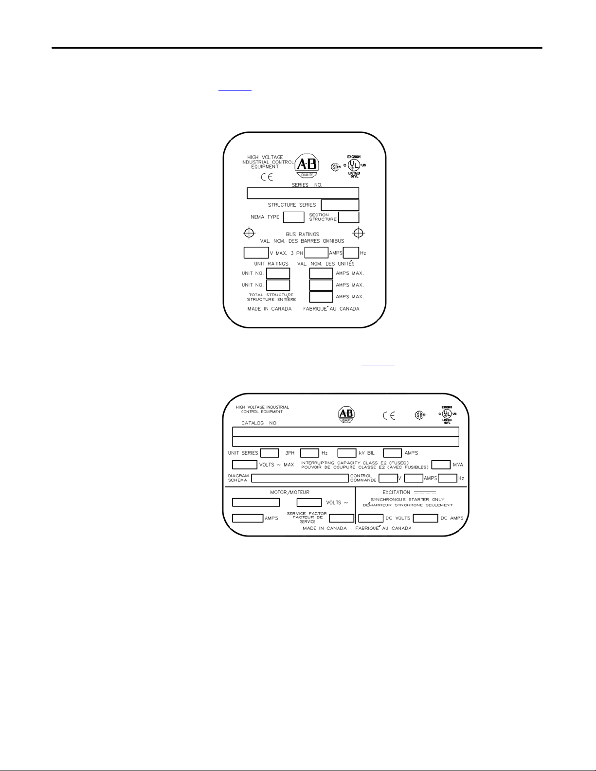
Starter Identification
A structure nameplate is attached to the right-side flange of the structure (see
Figure 1
). Refer to the nameplate for information such as series number, section
number, NEMA enclosure type, unit ratings and bus ratings.
Figure 1 - Typical Structure Nameplate
A unit nameplate is also found in the low voltage compartment with specific unit
motor application information (see Figure 2
).
Figure 2 - Typical Unit Nameplate
Refer to these nameplates whenever you contact Rockwell Automation for
assistance. Be prepared to provide such information as series number, structure
series, unit series, diagram schematic and catalog number.
2 Rockwell Automation Publication 1500-UM055G-EN-P - May 2013
Page 11

General Information Chapter 1
Prepared Space
When ordering a starter kit to complete a prepared space
following information to ensure the proper components are supplied.
(2)
, provide the
Series Number
Provide the series number from the structure with the prepared space. The
number is stamped on a nameplate on the right-hand flange of the starter (see
Figure 1
the starter.
). The series number is also available from the dimension drawings for
Motor Data
Provide the following motor data:
• Locked rotor current
• Full load current
• Maximum locked rotor time
• Acceleration time
• Motor service factor
• Motor horsepower
Recommended Torque Values
Starter Features
Provide information regarding any special features required for the starter kit.
Indicate if these features are different from the motor control features in the
existing, complete power cell.
When reinstalling components or when reassembling the cabinet, tighten the
following bolt sizes to the specified torque values:
Table 1 - Hardware Torque Values
1/4 in. hardware 8 N•m (6 lb•ft)
5/16 in . hardware 15 N•m ( 12 lb•ft)
3/8 in. hardware 27 N•m (20 lb•ft)
1/2 in. hardware 65 N•m (48 lb•ft)
(2) Not available on arc resistant cabinets.
Rockwell Automation Publication 1500-UM055G-EN-P - May 2013 3
Page 12

Chapter 1 General Information
Notes:
4 Rockwell Automation Publication 1500-UM055G-EN-P - May 2013
Page 13
Installation – Standard Enclosure
IMPORTANT
.
.
.
.
.
.
.
.
LV MV
LV MV
.
.
.
.
.
.
.
.
LV MV
LV MV
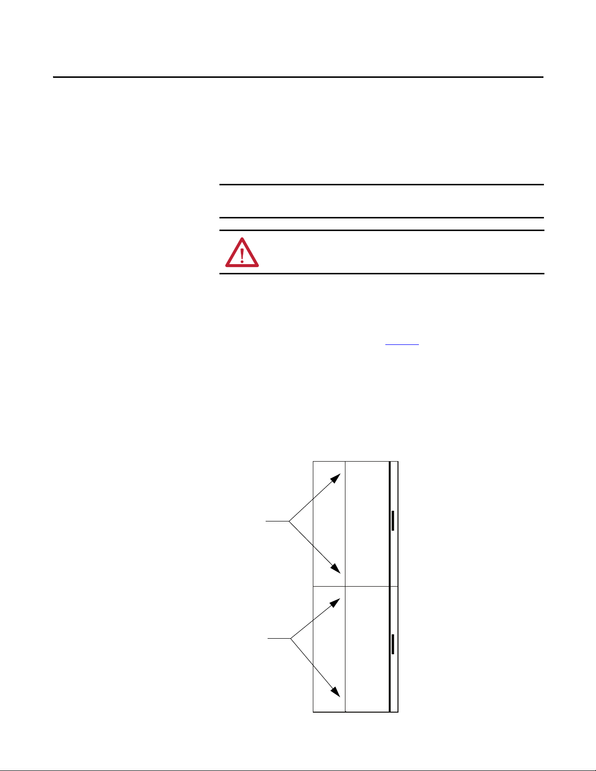
1/4-turn fasteners for
Upper Low Voltage Door
1/4-turn fasteners for
Lower Low Voltage Door
For information on the installation site preparation, see General Handling
Procedures for MV Products, Publication MV-QS050_-EN-P.
ATT EN TI ON : Use suitable personal protective equipment (PPE) per local codes
or regulations. Failure to do so may result in severe burns, injury or death.
Chapter 2
Door Opening Procedure
Opening the Low Voltage Doors
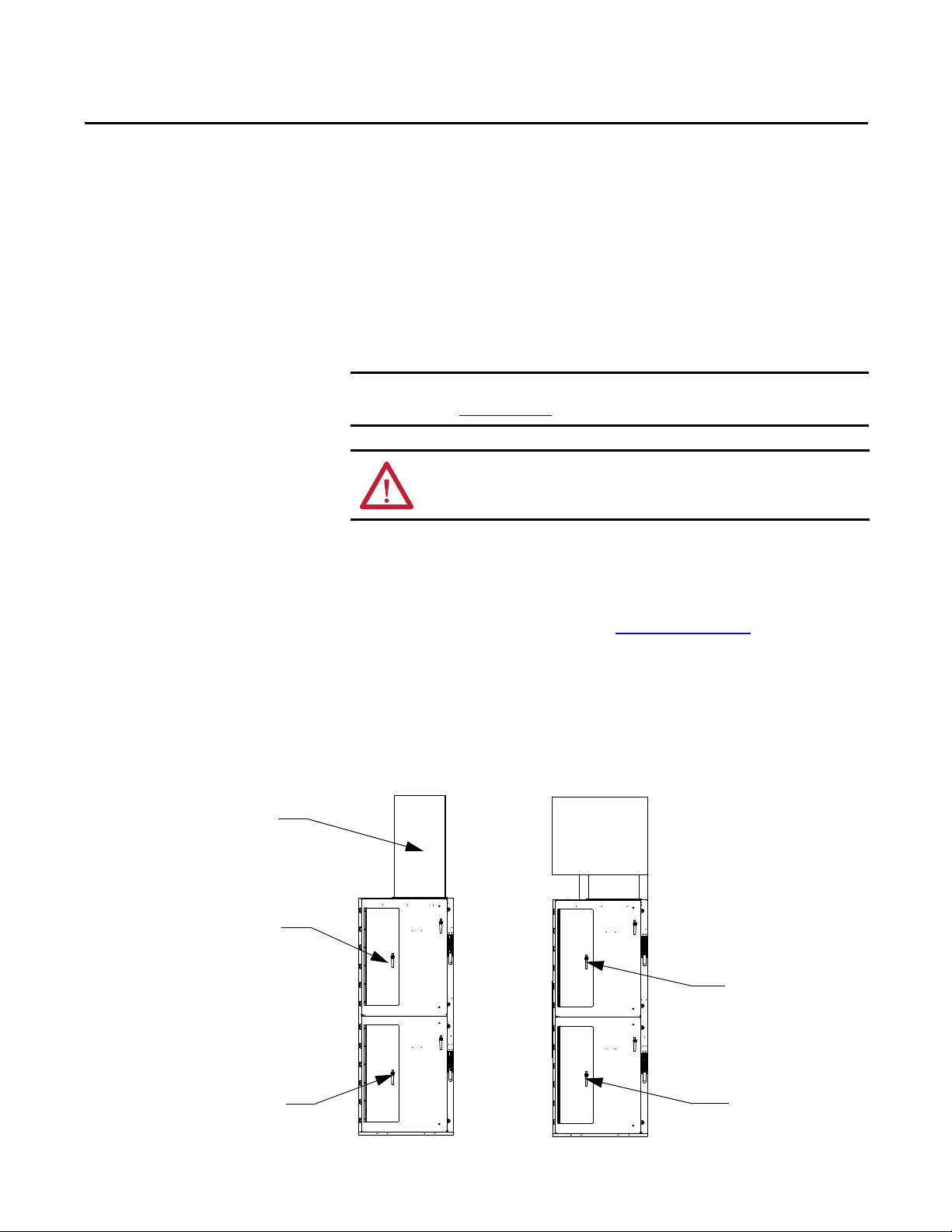
Low voltage doors are identified as LV in Figure 3.
1. To access the compartments for standard cabinets – use a flat-head
screwdriver and turn both of the 1/4-turn fasteners at least 90° in a
counterclockwise direction.
2. The door is now released and will swing open.
3. Reverse the procedure to secure the doors.
Figure 3 - Access to Low Voltage Compartments
Rockwell Automation Publication 1500-UM055G-EN-P - May 2013 5
Page 14
Chapter 2 Installation – Standard Enclosure
.
.
.
.
.
.
.
.
LV MV
LV MV
.
.
.
.
.
.
.
.
LV MV
LV MV
Door Locking Bolts for Upper
Medium Voltage Door
Door Locking Bolts for Upper
Medium Voltage Door
Isolation
Switch
Handles
IMPORTANT
Opening the Medium Voltage Doors
ATT EN TI ON : Medium voltage components are located behind the swing-out
low voltage panel (standard cabinets only). Complete the Power Lock-out
procedure (refer to Power Lock-out Procedure
attempting to open the swing-out low voltage panel. Failure to do so may result
in severe burns, injury or death.
ATT EN TI ON : Complete the Power Lock-out procedure (refer to Power Lock-out
Procedure on page 47 of Chapter 5) before beginning any service procedures to
the unit. Failure to do so may result in severe burns, injury or death.
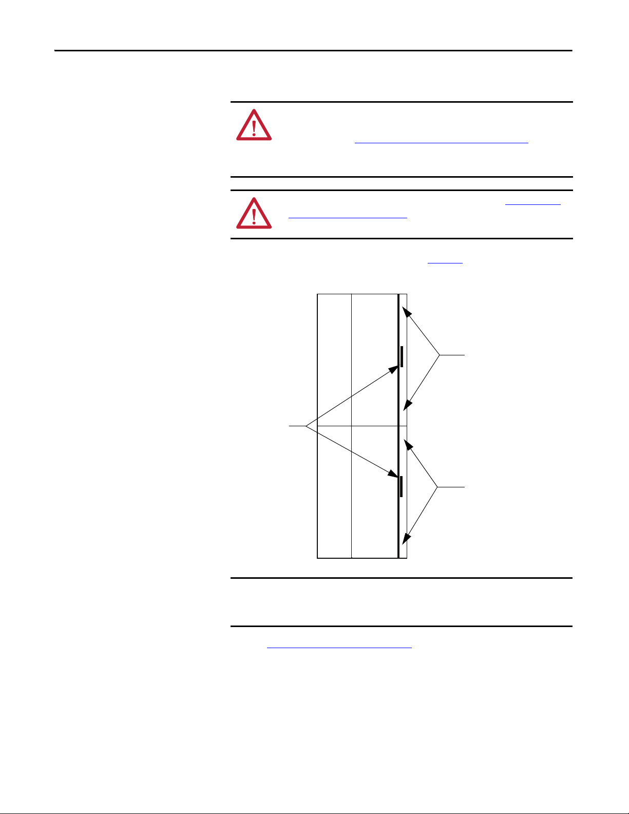
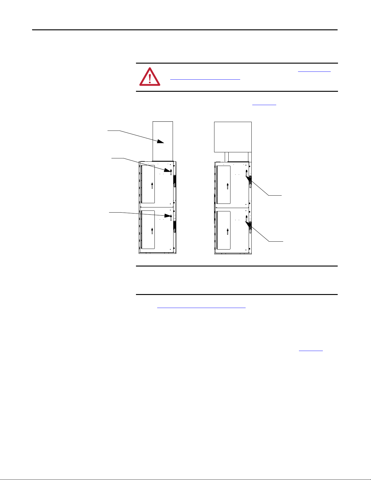
Medium voltage doors are identified as MV in Figure 4.
Figure 4 - Access to Medium Voltage Compartments
on page 47 of Chapter 5) before
Each medium voltage door has its own isolation switch handle and
interlocking safeguards. Upper and lower power cells are separated by an
isolation barrier.
Refer toAccess to the Power Bus on page 9 for the procedure to open the swing-
6 Rockwell Automation Publication 1500-UM055G-EN-P - May 2013
out low voltage panel behind the low voltage door (for standard cabinet only).
1. Electrically open the contactor by pressing the STOP button on the starter
or at the remote control location.
2. Move the isolation switch handle to the OFF position.
3. Unscrew the door locking bolts for medium voltage door.
Page 15

Installation – Standard Enclosure Chapter 2
IMPORTANT
TIP
IMPORTANT
4. The door is now released and will swing open.
5. Reverse the procedure to close the door.
Ensure that the swing-out low voltage panel is in its original position before
attempting to close the MV door. When closing the medium voltage door,
ensure all door locking bolts on the right side of the MV door are in place and
tightened until the door is flush with the flange
bolts. If the door is not securely fastened, it will not be possible to move the
isolation switch handle to the ON position.
ATT EN TI ON : Complete the Power Lock-out procedure (refer to Power Lock-out
Procedure on page 47 of Chapter 5) before beginning any service procedures to
the unit. Failure to do so may result in severe burns, injury or death.
. Do not overtighten the
Anchoring
Place the controller in the desired installation location. Use 12 mm (1/2 in.
[M12]) floor mounting bolts to securely fasten the controller to the mounting
surface. See Figure 5
cabinet.
as an example of the location of the mounting holes in the
Refer to Dimension Drawing provided with order documentation for additional
details related to cabinet floor plan.
Pre-determined cabinets have been designed for Uniform Building Code (UBC)
seismic zone 1, 2A, 2B, 3 and 4, and IBC (International Building Code) seismic
activity without overturning or lateral movement, provided they are securely
mounted according to UBC, IBC and local building codes. This can include
concrete pad design, steel floor design and the sizing of cabinet anchors.
Concrete floor cutouts must not be adjacent to floor anchor bolts and must be
sized to seismic load. Consult factory if floor mounting must be reviewed by an
accredited engineer. Many jurisdictions require an engineer from the local area
to review the design. Seismic qualification does not indicate that the
equipment will function properly after a seismic event.
Rockwell Automation Publication 1500-UM055G-EN-P - May 2013 7
Page 16
Chapter 2 Installation – Standard Enclosure
TIP
Figure 5 - Cabinet Floor Plan
Joining Sections
NOTES FOR SEISMIC APPLICATIONS
• For installations on concrete – the minimum depth and radius of
concrete supporting the cabinet anchors is dependent on seismic loads.
Refer to important information above.
• For installations on a metal structure – the metal plate depth and cabinet
anchoring method is dependent on seismic loads.
Joining hardware can be found in a package mounted on the front of the
shipping skid. Refer to publication MV-QS050_-EN-P for level floor surface
requirements.
1. Position the left side of the section on a level surface and secure the section
in place with 12 mm (1/2 in. [M12]) floor mounting bolts (refer
to Anchoring
2. When joining NEMA Type 12, apply a continuous 3 mm (1/8 in.) wide
bead of silicon sealer around the perimeter of one section.
3. Remove the side bus access covers if applicable.
4. Position the right section against the left section. Ensure that the surface is
level.
on page 7).
8 Rockwell Automation Publication 1500-UM055G-EN-P - May 2013
Page 17
Installation – Standard Enclosure Chapter 2
F
r
o
n
t
F
r
o
n
t
Side Bus
Access Cover
0.219 Pilot
Holes (5x)
0.281 Pilot
Holes (5x)
0.281 Pilot
Holes (5x)
0.219 Pilot
Holes (3x)
5. Secure the sections together using the 1/4-20 self-tapping screws. Thread
the screw through the 7 mm (0.281 in.) clearance hole to the
corresponding 6 mm (0.219 in.) pilot hole. To access the front clearance
holes of the left-side cabinet, open the medium voltage doors. To access the
rear clearance holes remove the rear covers of the starter. If rear access is
not available, refer to Front Access– Access to Power Bus
on page 11.
6. Secure the right section to the floor using 12 mm (1/2 in. [M12]) floor
mounting bolts (refer to Anchoring
Figure 6 - Joining Sections
on page 7).
Access to the Power Bus
ATT EN TI ON : This procedure requires contact with medium voltage
components. To avoid shock hazards, lock out incoming power before working
on the equipment (refer to Power Lock-out Procedure
Verify with a hot stick or appropriate voltage measuring device that all circuits
on page 47 of Chapter 5).
are voltage free. Failure to do so may result in severe burns, injury or death.
Rear Access
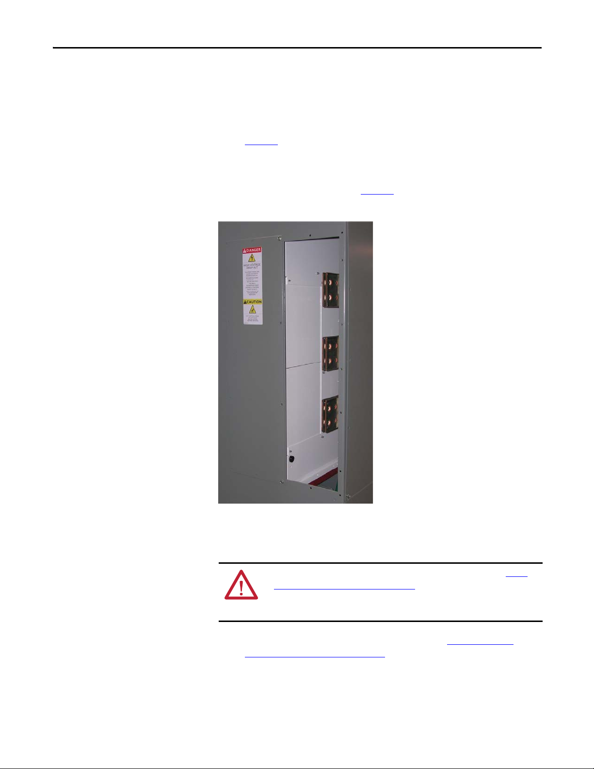
1. Remove the hardware securing the center rear bus access cover (see
Figure 7
).
2. Remove the center rear bus access cover.
Rockwell Automation Publication 1500-UM055G-EN-P - May 2013 9
Page 18
Chapter 2 Installation – Standard Enclosure
Side Bus
Access Cover
Center Rear Bus
Access Cove r
3. Once the rear bus cover is removed, you will see the three power bus bars
and the ground bus bar (see Figure 8
Figure 7 - Access to Power Bus from Side and Rear of Cabinet
).
Figure 8 - Bus Bars from Back Access
10 Rockwell Automation Publication 1500-UM055G-EN-P - May 2013
Page 19
Installation – Standard Enclosure Chapter 2
Side Access
A side bus access cover is located on each side of the controller.
1. Remove the hardware from the appropriate side bus access cover (see
Figure 7
2. Remove the side bus access cover.
3. Once the side bus access cover is removed, you will see the three power bus
bars and the ground bus (see Figure 9
Figure 9 - Side Bus Access Cover Removed
).
).
Front Access– Access to Power Bus
ATT EN TI ON : To avoid shock hazards, lock out incoming power (refer to Power
Lock-out Procedure on page 47 of Chapter 5) before working on the equipment.
Verify with a hot stick or appropriate voltage measuring device that all circuits
are voltage free. Failure to do so may result in severe burns, injury or death.
1. Complete the Power Lock-out Procedure (refer to Power Lock-out
Procedure on page 47 of Chapter 5) for both medium voltage power cells
and the power bus.
2. Open the doors and remove the hinge pins.
Rockwell Automation Publication 1500-UM055G-EN-P - May 2013 11
Page 20
Chapter 2 Installation – Standard Enclosure
Remove self-tapping screws
from center vertical channel
Control Wiring Harness
3. Open the low voltage cell doors (refer to Opening the Low Voltage Doors
on page 5).
4. Disconnect the control wiring harness from the wire plug at the lower left
side of the contactor.
5. Remove the two self-tapping screws from the center vertical channel (see
Figure 10
).
6. Pull on the center vertical channel to swing out the low voltage panel.
Figure 10 - Center Vertical Channel
12 Rockwell Automation Publication 1500-UM055G-EN-P - May 2013
Page 21
Installation – Standard Enclosure Chapter 2
Current Transfo rmers
Remove self-tapping screws
from barrier assembly
Glass-polyester barrier
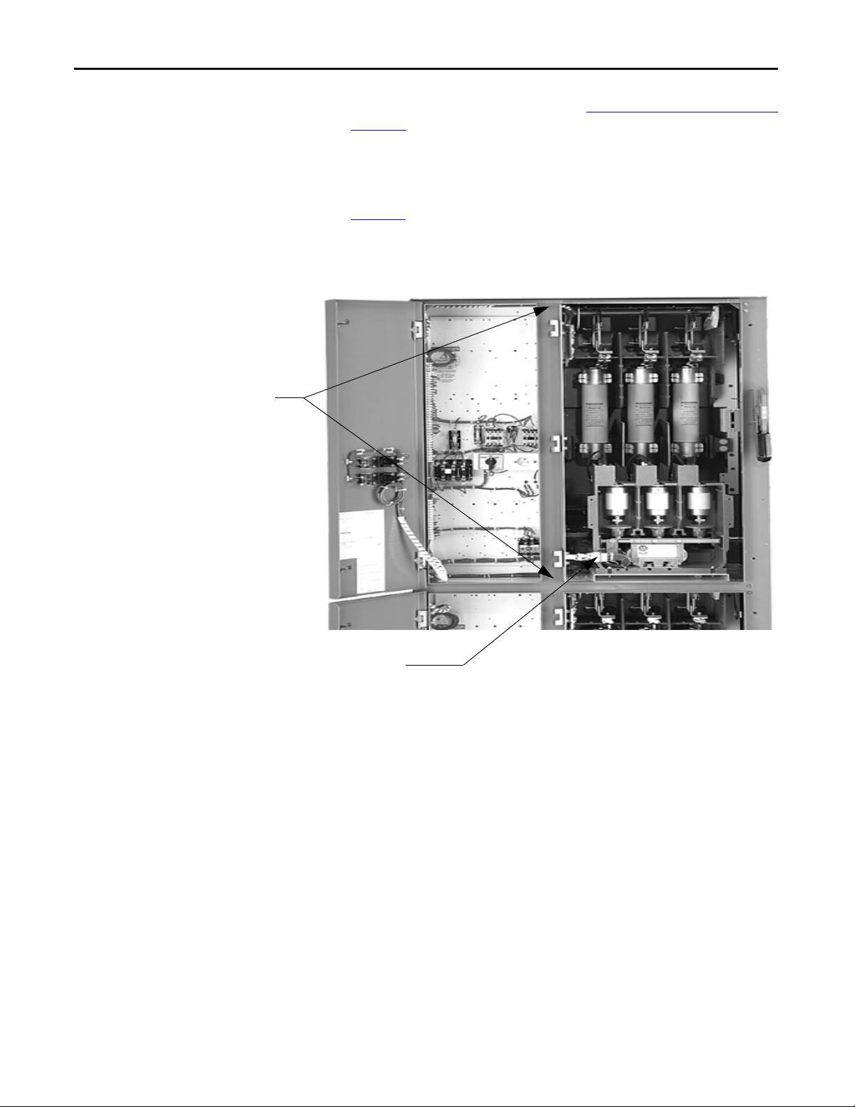
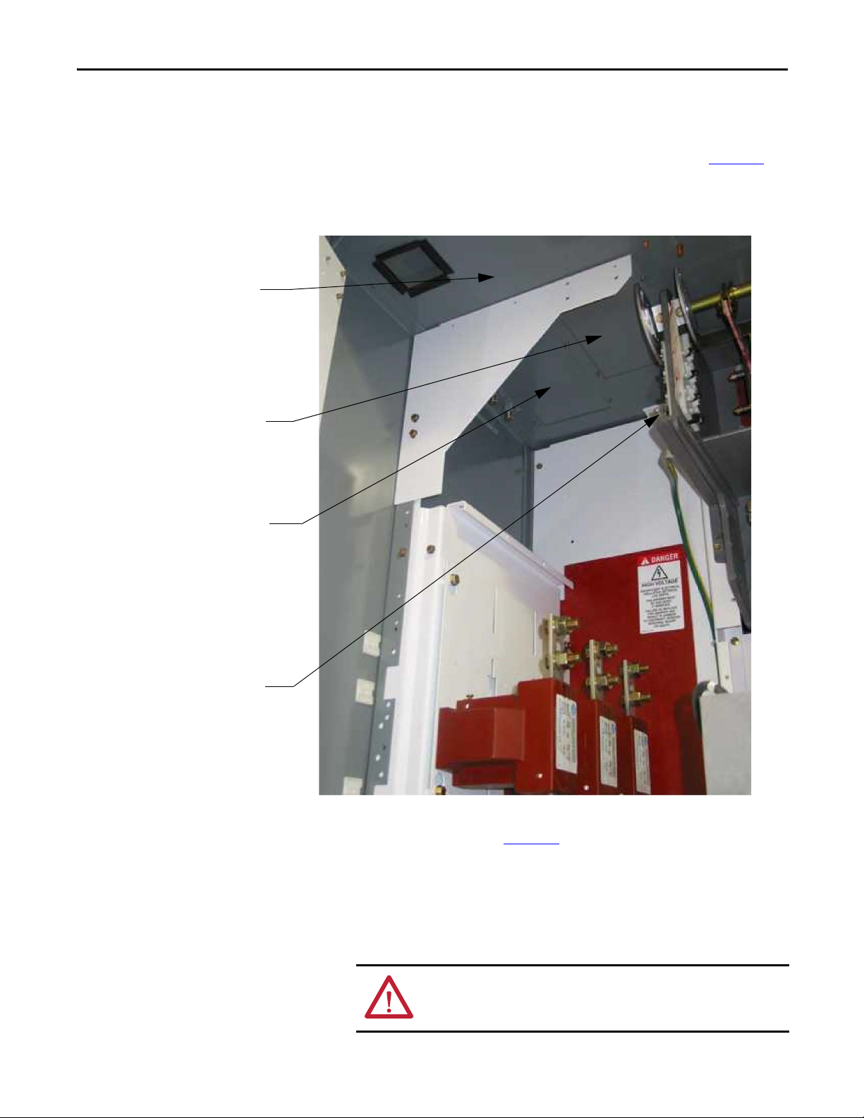
7. Remove each glass-polyester barrier located in front of the current
transformers (see Figure 11
Figure 11 - Removing Glass-polyester Barrier
).
8. Remove the retaining screw from the cable duct barrier and remove the
barrier (see Figure 12
).
9. Remove the two retaining screws from the cable duct boot and remove the
boot (see Figure 12
).
Rockwell Automation Publication 1500-UM055G-EN-P - May 2013 13
Page 22
Chapter 2 Installation – Standard Enclosure
Current Transformers
CT Mounting Plate
Loosen Retaining Screws
Cable Duct Boot
Remove Retaining Screws
Cable Duct Barrier
Remove four self-
tapping screws from
each Bus Access Cover
Figure 12 - Removing Cable Duct Boot and Barrier
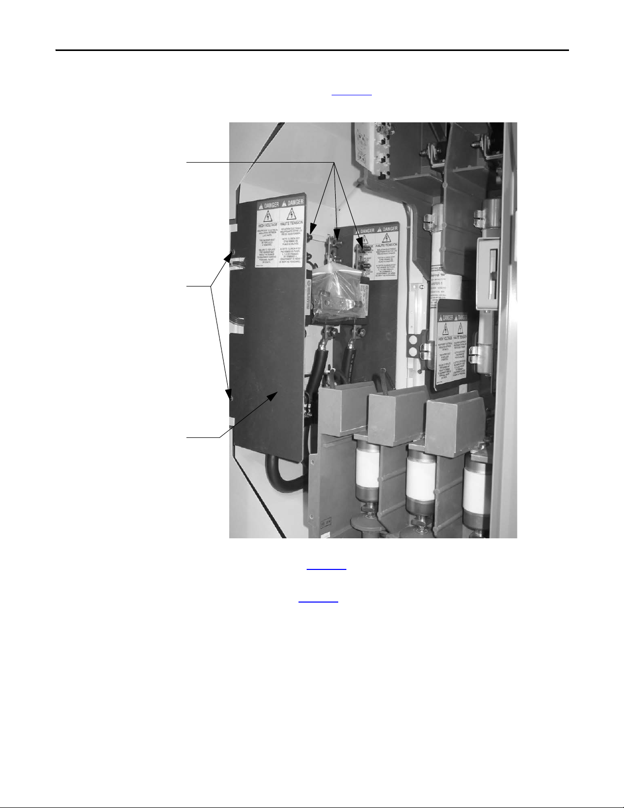
10. To access the left side of the power bus, locate the two bus access covers at
the rear, left side of the power cell. Remove the four self-tapping screws
from each cover and remove the covers (see Figure 13
Figure 13 - Removing Bus Access Covers
).
14 Rockwell Automation Publication 1500-UM055G-EN-P - May 2013
Page 23
Installation – Standard Enclosure Chapter 2
Contactor Bus Bars
Mounting Bolts
Trailer Fuse Block
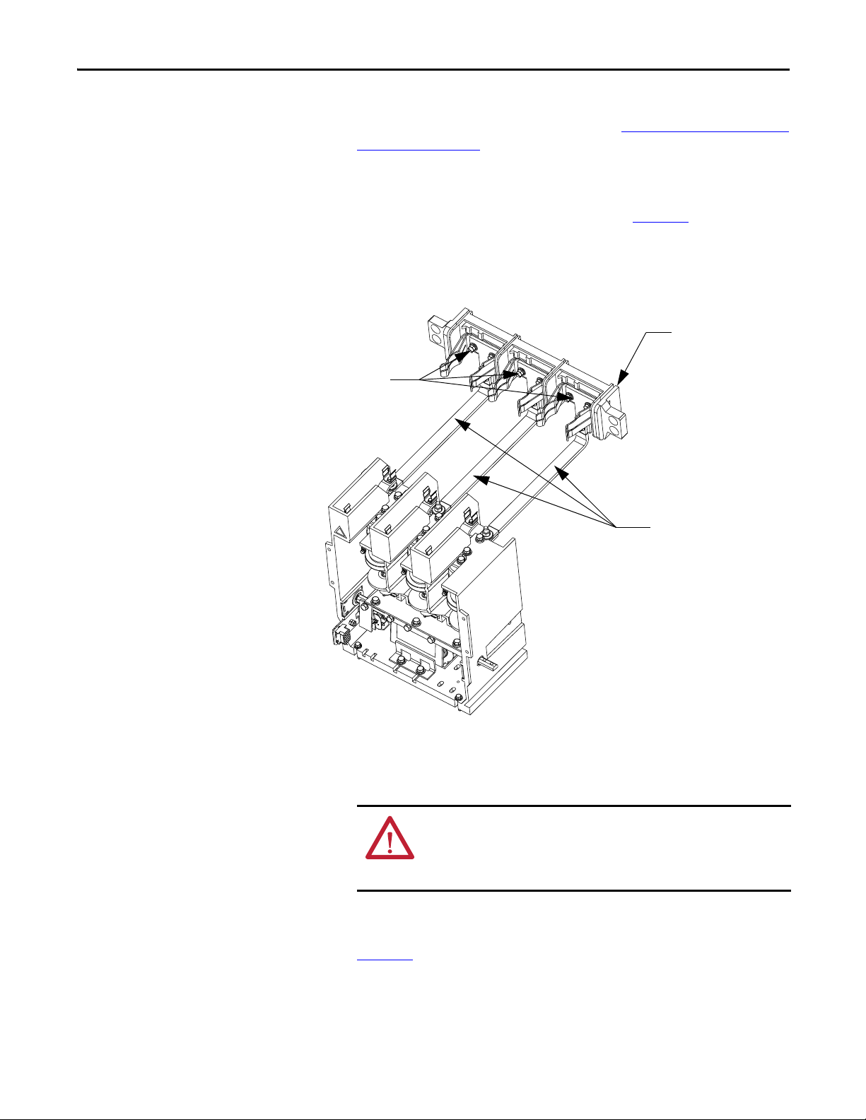
11. If access to the right side of the power bus is required, remove the vacuum
contactor from the upper power cell (refer to Removing the Contactor
page 52 of Chapter 5).
12. Remove the power fuses from the isolation switch.
13. Remove the interphase barriers from the trailer fuse block by raising them
vertically up and out of the mounting slots (see Figure 14
).
14. Use a 9/16-in. socket to remove the contactor bus bars from the isolation
switch trainer fuse block.
Figure 14 - Contactor Bus Bars (Trailer Fuse Block for Clip-on Fuses Shown)
on
15. Disconnect the secondary control wiring from the control power
transformer (CPT) and remove the CPT mounting plate. Leave the CPT
attached to the plate.
ATTENTION: The CPT is heavy and assistance may be required to safely
remove and transport the unit. Use caution when removing the CPT.
Failure to do so may result in personal injury and/or damage to the
equipment.
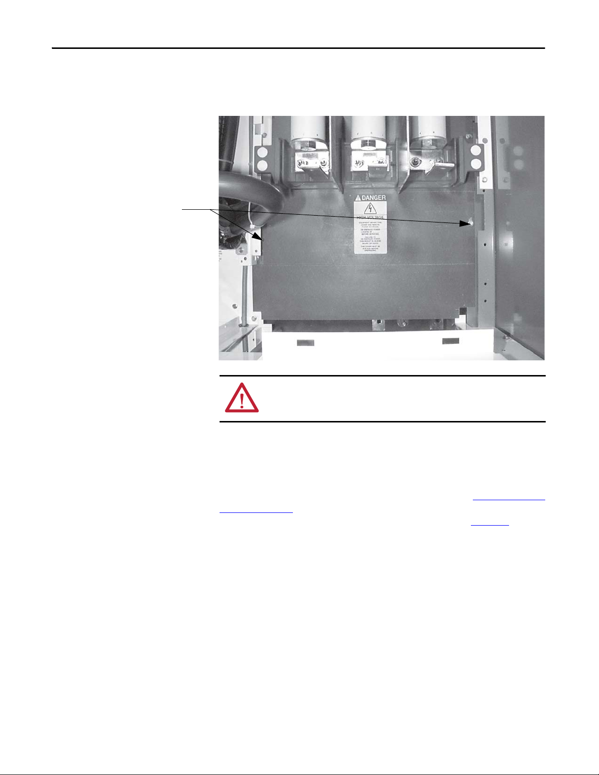
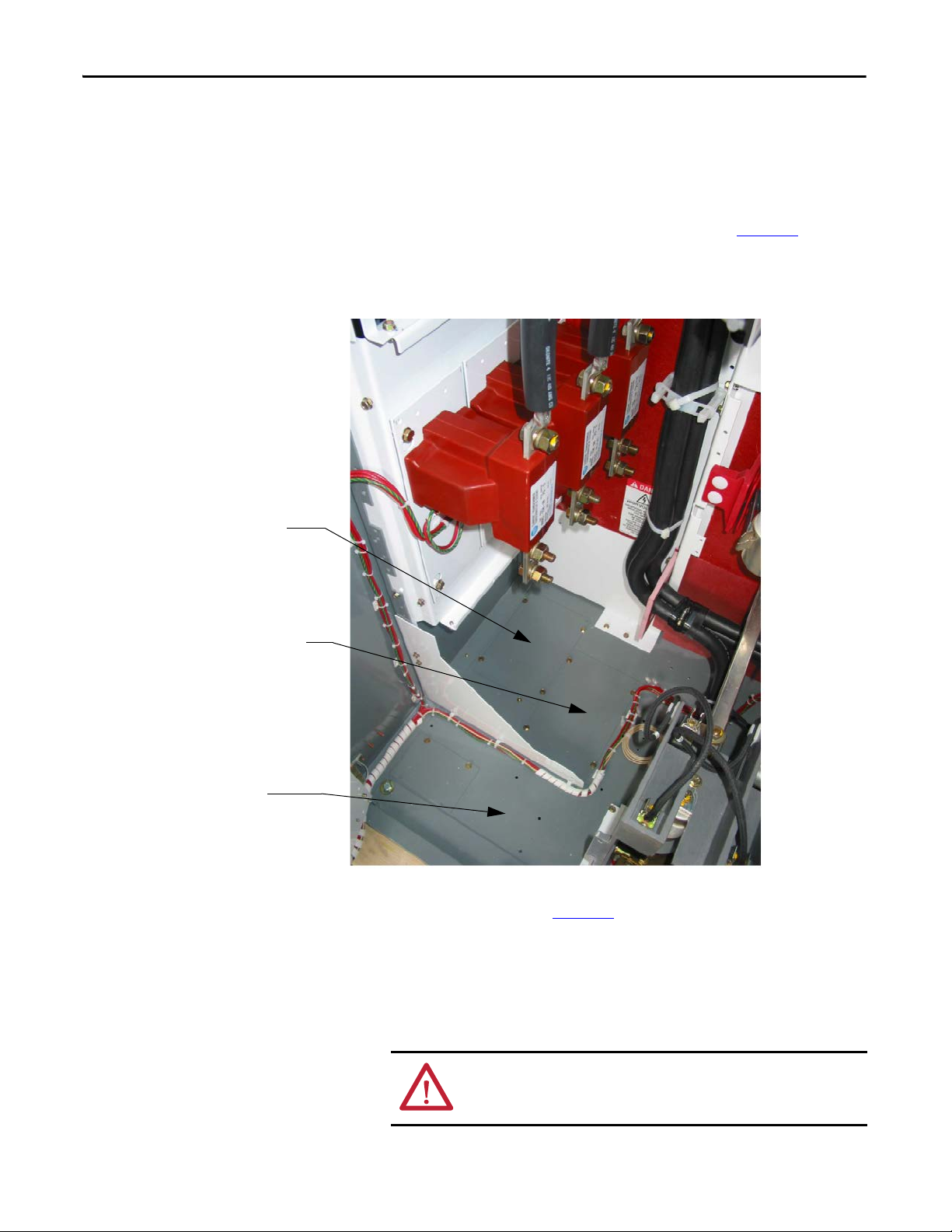
16. To access the right side of the power bus, remove the self-tapping screws
from the lower glass-polyester bus access cover and remove the cover (see
Figure 15
Rockwell Automation Publication 1500-UM055G-EN-P - May 2013 15
).
Page 24
Chapter 2 Installation – Standard Enclosure
Remove self-tapping screws
17. Reverse the procedure to reassemble the cabinet. Ensure that the barriers
are put back in place and all parts and tools are accounted for.
Figure 15 - Access to Right Side of Power Bus
ATT EN TI ON : Ensure all barriers are replaced before re-energizing the
equipment. Failure to do so may result in electrical faults and cause damage to
equipment or serious injury to personnel.
Front Access – Bottom Exiting Load Cables
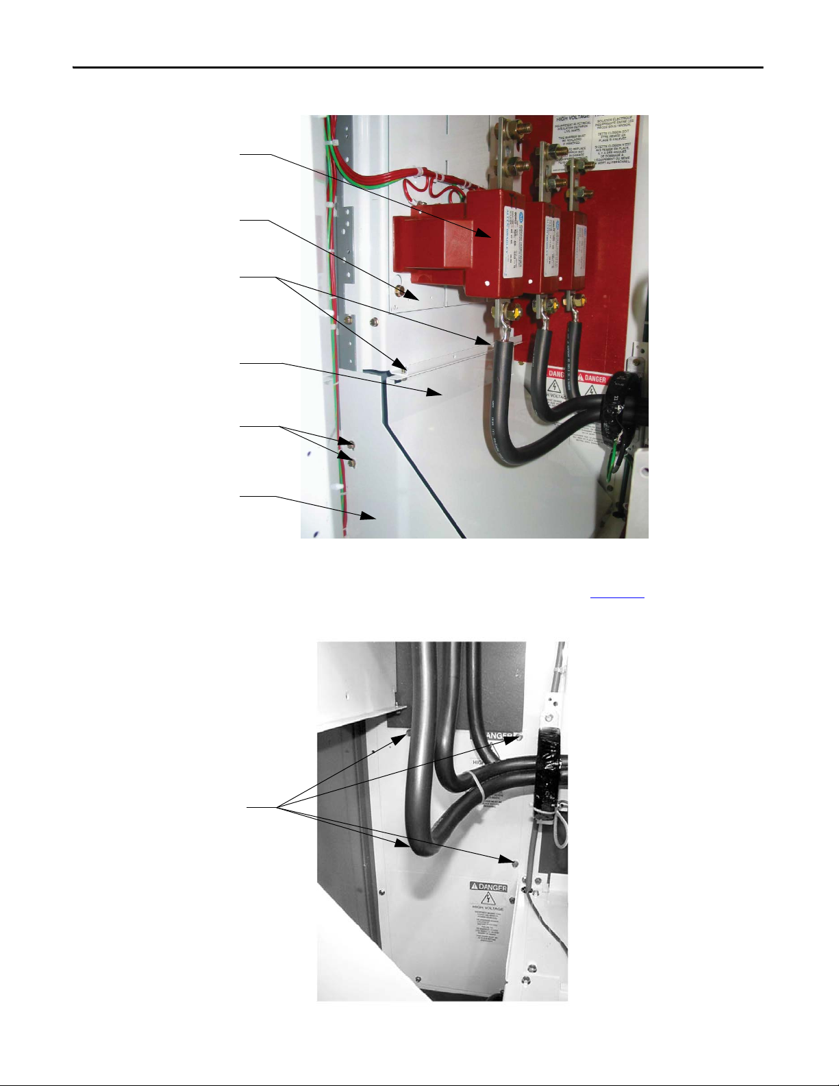
If the cables in your cabinet exit from the bottom, the procedure to access the power
bus is almost identical to the one above. Follow the procedure for To p Ex i ti n g L o a d
Cables on page 19, but remove the cable duct barrier and cable duct boot from the
top of the lower power cell, rather than those at the bottom (see Figure 16
).
16 Rockwell Automation Publication 1500-UM055G-EN-P - May 2013
Page 25
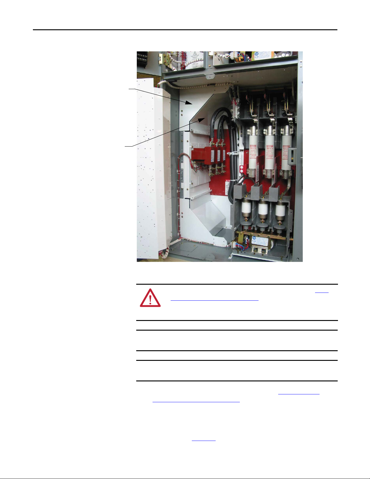
Figure 16 - Bottom Cable Exit Configuration
Cable Duct Barrier
Cable Duct Boo t
IMPORTANT
IMPORTANT
Installation – Standard Enclosure Chapter 2
Load Cable Connections
ATT EN TI ON : To avoid shock hazards, lock out incoming power (refer to Power
Lock-out Procedure on page 47 of Chapter 5) before working on the equipment.
Verify with a hot stick or appropriate voltage measuring device that all circuits
are voltage free. Failure to do so may result in severe burns, injury or death.
The current transformers may be positioned for top or bottom cable exit.
Follow the appropriate procedure described for your starter configuration.
Refer to Dimensional Drawings provided with order documentation for
additional details.
1. Complete the Power Lock-out procedure (refer to Power Lock-out
Procedure on page 47 of Chapter 5).
2. Open the MV power cell door.
3. Remove the cable duct boot at the top of the cabinet for top exiting load
cables, or remove the one at the bottom of the cabinet for bottom exiting
load cables (see Figure 17
Rockwell Automation Publication 1500-UM055G-EN-P - May 2013 17
).
Page 26
Chapter 2 Installation – Standard Enclosure
Remove Cable Duct Boot to
access Load Cable Conduit
opening for cables exiting
from bottom Power Cell
Current Transformer
Mounting Plate
Connect Load Cables to
Current Transformers
TIP
Figure 17 - Access to Load Cable Conduit Openings (Top exit cable configuration shown)
(LV panels removed for clarity)
4. Remove the appropriate load cable conduit openings in the top or bottom
of the cabinet (see Figure 18
or Figure 19).
Refer to Dimensional Drawings provided with order documentation for
additional details.
18 Rockwell Automation Publication 1500-UM055G-EN-P - May 2013
Page 27
Installation – Standard Enclosure Chapter 2
Ground Lug
Load Ca ble Conduit
opening for cables from
bottom power cell
Load cable Condui t
Opening for cables
from top power cell
Top of Cabinet
Top Exiting Load Cables
5. Load cables for the bottom power cell should be routed first. Pull the
cables into the cabinet through the appropriate opening (see Figure 18
Run the cables behind the current transformer mounting plate and into
the bottom power cell.
Figure 18 - Load Cable Conduit Openings (Top Exit Shown)
).
6. For the top power cell, pull the cables into the cabinet through the
appropriate opening (see Figure 18
).
7. Connect the cables to the current transformers and tighten the
connections to 65 N•m (48 lb•ft).
8. Connect cable shields to the ground lug.
9. Reinstall the cable duct boot and reassemble the cabinet.
ATTENTION: Ensure all barriers are replaced before re-energizing the
equipment. Failure to do so may result in electrical faults and cause
damage to equipment or serious injury to personnel.
Rockwell Automation Publication 1500-UM055G-EN-P - May 2013 19
Page 28
Chapter 2 Installation – Standard Enclosure
TIP
Load Cable Cond uit Opening
for cables from top power cell
Load Cable Conduit Opening for
cables from bottom power cell
Bottom of Cabinet
Bottom Exiting Load Cables
Follow steps 1-4 from the previous section.
5. Load cables for the top power cell should be routed first. Pull the cables
into the cabinet through the appropriate opening (see Figure 19
cables behind the current transformer mounting plate and into the top
power cell.
Figure 19 - Load Cable Conduit Openings (Bottom Exit Shown)
). Run the
6. For the bottom power cell, pull the cables into the cabinet through the
appropriate opening (see Figure 19
7. Connect the cables to the current transformers and tighten the
connections to 65 N•m (48 lb•ft).
8. Connect cable shields to the ground lug.
9. Reinstall the cable duct boot and reassemble the cabinet.
ATTENTION: Ensure all barriers are replaced before re-energizing the
equipment. Failure to do so may result in electrical faults and cause
damage to equipment or serious injury to personnel.
20 Rockwell Automation Publication 1500-UM055G-EN-P - May 2013
).
Page 29
Chapter 3
IMPORTANT
LV
MV
LV
MV
LV
MV
LV
MV
Chimney
Upper Low Voltage
Door handle
Lower Low Voltage
Door handle
Plenum
Upper Low Voltage
Door handle
Lower Low Volt age
Door handle
Installation – Arc-Resistant Enclosure
(ArcShield)
This installation section contains information on arc resistant styles of
enclosures, referred to in this manual as “ArcShield”.
For information on the installation site preparation, see Publication
MV-QS050_-EN-P
ATT EN TI ON : Use suitable personal protective equipment (PPE) per local codes
or regulations. Failure to do so may result in severe burns, injury or death.
.
Door Opening Procedure
Opening the Low Voltage Doors
Low voltage doors are identified as LV in Figure 17 on page 18.
1. To access the compartments for ArcShield cabinets – turn the release
handle counter-clockwise 90º.
2. The door is now released and will swing open.
3. Reverse the procedure to secure the door.
Figure 20 - Access to Low Voltage Compartments
Rockwell Automation Publication 1500-UM055G-EN-P - May 2013 21
Page 30
Chapter 3 Installation – Arc-Resistant Enclosure (ArcShield)
LV
MV
LV
MV
LV
MV
LV
MV
Chimney
Upper Low Voltage
Door handle
Lower Low Voltage
Door handle
Plenum
Upper Low Voltage
Door handle
Lower Low Volt age
Door handle
IMPORTANT
Opening the Medium Voltage Doors
ATT EN TI ON : Complete the Power Lock-out procedure (refer to Power Lock-out
Procedure on page 47 of Chapter 5) before beginning any service procedures to
the unit. Failure to do so may result in severe burns, injury or death.
Medium voltage doors are identified as MV in Figure 21.
Figure 21 - Access to Medium Voltage Compartments
Each medium voltage door has its own isolation switch handle and
interlocking safeguards. Upper and lower power cells are separated by an
isolation barrier.
Refer toAccess to the Power Bus on page 26 for the procedure to open the swingout low voltage panel behind the low voltage door (for standard cabinet only).
1. Electrically open the contactor by pressing the STOP button on the starter
or at the remote control location.
2. Move the isolation switch handle to the OFF position (see Figure 22
3. Turn the release handle counter-clockwise 90 degrees.
).
4. Unbolt the door locking bolts for medium voltage door.
5. The door is now released and will swing open.
22 Rockwell Automation Publication 1500-UM055G-EN-P - May 2013
Page 31

Installation – Arc-Resistant Enclosure (ArcShield) Chapter 3
IMPORTANT
TIP
TIP
6. Reverse the procedure to close the door. Door lock bolts must be
adequately tightened (refer to Recommended Torque Values
Chapter 1 for torque values).
When closing the medium voltage door, ensure all door locking bolts
on the right side of the MV door are in place and tightened until the
door is flush with the flange
door is not securely fastened, it will not be possible to move the
isolation switch handle to the ON position.
On all ArcShield starters, the sticker in Figure 22 is attached to each
door for your reference.
Figure 22 - Label on Arc Resistant Door
. Do not overtighten the bolts. If the
on page 3 of
Anchoring
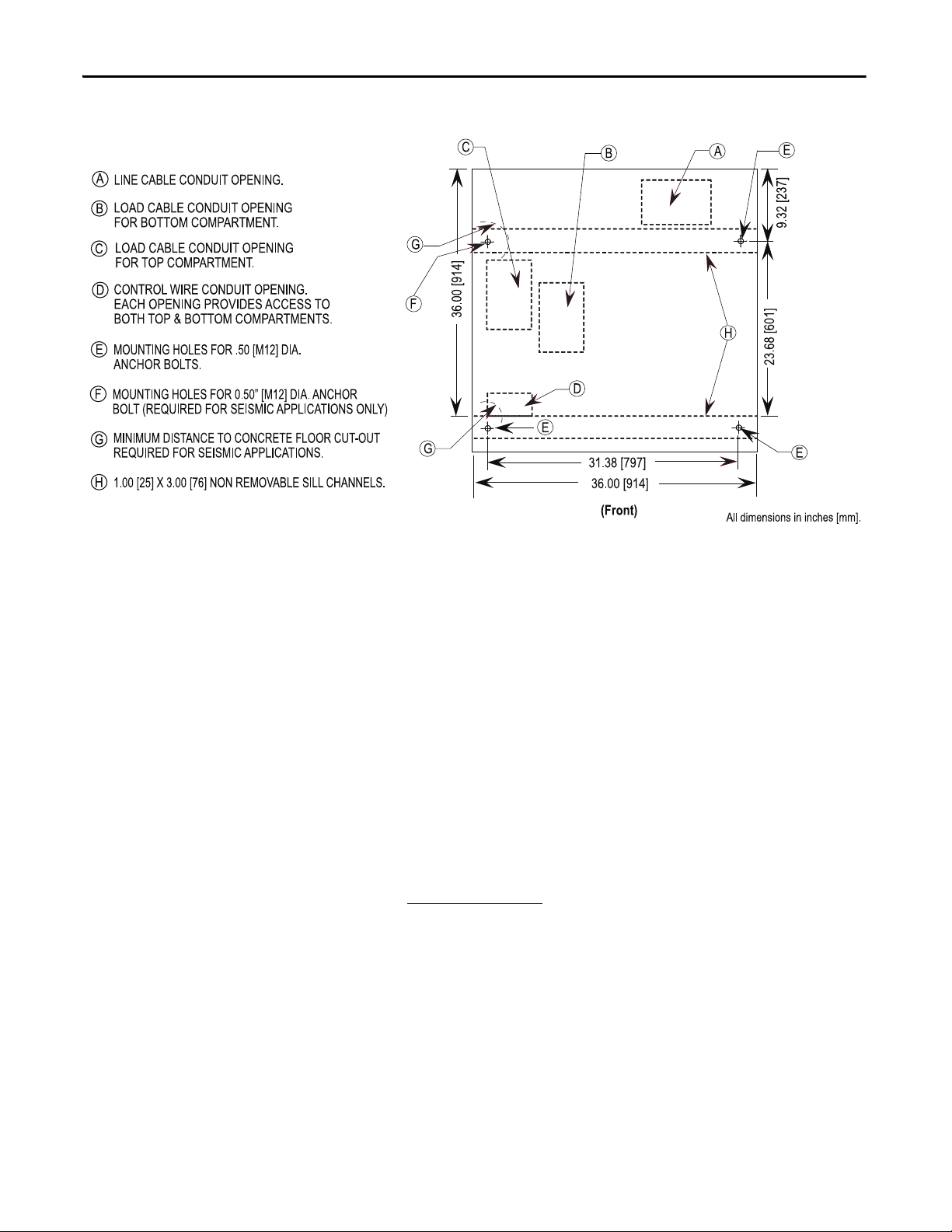
Place the controller in the desired installation location. Use 12 mm (1/2 in.
[M12]) floor mounting bolts to securely fasten the controller to the mounting
surface. See Figure 23
cabinet.
Rockwell Automation Publication 1500-UM055G-EN-P - May 2013 23
as an example of the location of the mounting holes in the
Refer to Dimension Drawing provided with order documentation for additional
details related to cabinet floor plan.
Page 32

Chapter 3 Installation – Arc-Resistant Enclosure (ArcShield)
IMPORTANT
5.25 [133]
31.38 [797]
36.00 [914]
36.00 [914]
16.17 [411]
30.00 [762]
2.31 [59]
4.62 [117]
9.32 [237]
23.68 [601]
7.50 [191]
4.88 [124]
13.05 [331]
FOR TOP COMPARTMENT.
LOAD CABLE CONDUIT OPENING
MOUNTING HOLES FOR .50 [M12] DIA.
ANCHOR BOLTS.
F
D
C
LINE CABLE CONDUIT OPENING.
LOAD CABLE CONDUIT OPENING
FOR BOTTOM COMPARTMENT.
B
A
5.68 X 9.00
[144 X 229]
3.00 X 5.00
[76 X 127]
D
B
H
E
CONTROL WIRE CONDUIT OPENING.
BOTH TOP & BOTTOM COMPARTMENTS.
EACH OPENING PROVIDES ACCESS TO
BOLT (REQUIRED FOR SEISMIC APPLICATIONS ONLY)
MOUNTING HOLES FOR 0.50” [M12] DIA. ANCHOR
[144 X 229]
5.68 X 9.00
C
5.68 X 9.00
[144 X 229]
A
E
(Front)
G
REQUIRED FOR SEISMIC APPLICATIONS.
MINIMUM DISTANCE TO CONCRETE FLOOR CUT-OUT
H
1.00 [25] X 3.00 [76] NON REMOVABLE SILL CHANNELS.
F
E
E
G
G
Pre-determined cabinets have been designed for Uniform Building Code (UBC)
seismic zone 1, 2A, 2B, 3 and 4, and IBC (International Building Code) seismic
activity without overturning or lateral movement, provided they are securely
mounted according to UBC, IBC and local building codes. This can include
concrete pad design, steel floor design and the sizing of cabinet anchors.
Concrete floor cutouts must not be adjacent to floor anchor bolts and must be
sized to seismic load. Consult factory if floor mounting must be reviewed by an
accredited engineer. Many jurisdictions require an engineer from the local area
to review the design. Seismic qualification does not indicate that the
equipment will function properly after a seismic event.
ATT EN TI ON : Complete the Power Lock-out procedure (refer to Power Lock-out
Procedure on page 47 of Chapter 5) before beginning any service procedures to
the unit. Failure to do so may result in severe burns, injury or death.
Figure 23 - Cabinet Floor Plan
24 Rockwell Automation Publication 1500-UM055G-EN-P - May 2013
NOTES FOR SEISMIC APPLICATIONS
• For installations on concrete – the minimum depth and radius of
concrete supporting the cabinet anchors is dependent on seismic loads.
Refer to important information above.
• For installations on a metal structure – the metal plate depth and cabinet
anchoring method is dependent on seismic loads.
Page 33

Installation – Arc-Resistant Enclosure (ArcShield) Chapter 3
TIP
TIP
Power Bus
cutout holes
must align
Silicone is applied around
power bus cutout area to
prevent gas leakage
between joined cabinets
Joining Sections
Joining hardware can be found in a package mounted to the front of the
shipping skid.
Refer to publication MV-QS050_-EN-P for level floor surface requirements.
1. Position the left side section on a level surface and secure the section in
place with 12 mm (1/2 in. [M12]) floor mounting bolts (refer
to Anchoring
on page 23).
2. When joining ArcShield sections, apply a continuous 3 mm (1/8 in.) wide
bead of silicone sealer around the perimeter of one section.
3. Remove the side bus access covers if applicable.
4. Position the right section against the left section. Ensure that the surface is
level.
5. Secure the sections together using the 1/4-20 self-tapping screws. Thread
the screw through the 7 mm (0.281 in.) clearance hole to the
corresponding 6 mm (0.219 in.) pilot hole. To access the front clearance
holes of the left-side cabinet, open the medium voltage doors. To access the
rear clearance holes remove the rear covers of the starter. If rear access is
not available, refer to Front Access– Access to Power Bus
on page 11 of
Chapter 2. When joining the ArcShield sections, use the provided 1/4-20
thread fasteners to secure the perimeter of the horizontal bus opening,
ensure all bolts are installed. (Before joining sections together, ensure there
is a silicone seal around the bus bar opening.)
6. Secure the right section to the floor using 12 mm (1/2 in. [M12]) floor
mounting bolts (refer to Anchoring
Figure 24 - Joining Sections
on page 23).
Rockwell Automation Publication 1500-UM055G-EN-P - May 2013 25
Page 34

Chapter 3 Installation – Arc-Resistant Enclosure (ArcShield)
Side Bus Access Cover
Center Rear Bus Access Cover
Access to the Power Bus
ATT EN TI ON : This procedure requires contact with medium voltage
components. To avoid shock hazards, lock out incoming power before working
on the equipment (refer to Power Lock-out Procedure
Verify with a hot stick or appropriate voltage measuring device that all circuits
are voltage free. Failure to do so may result in severe burns, injury or death.
on page 47 of Chapter 5).
Rear Access
1. Remove the hardware securing the center rear bus access cover (see
Figure 25
2. Remove the center rear bus access cover.
3. Once the rear bus cover is removed you will see the three power bus bars
and ground bus (see Figure 27
Figure 25 - Access to Power Bus from Side and Rear of Cabinet
).
).
Side Access
A side bus access cover is located on each side of the controller.
1. Remove the hardware from the appropriate side bus access cover.
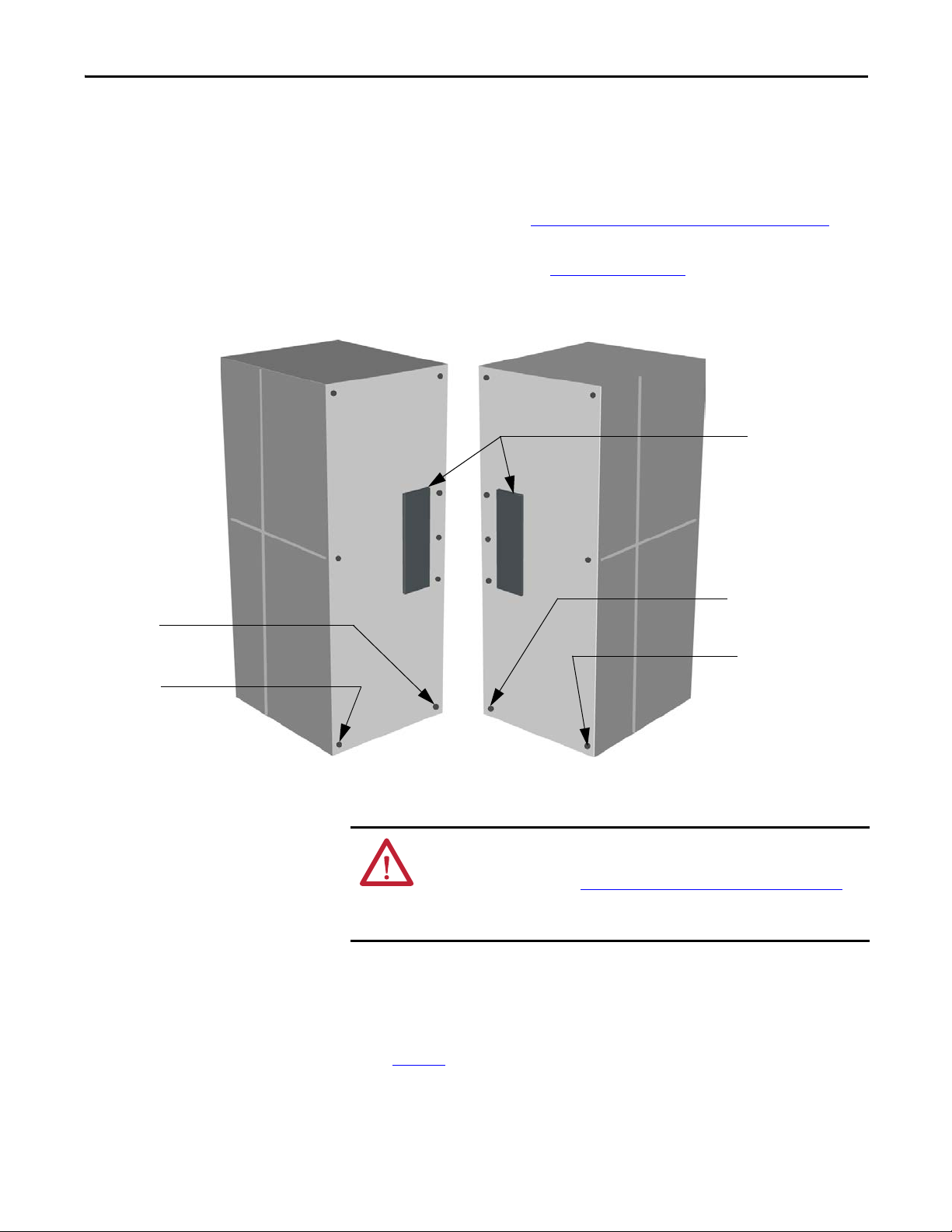
2. Remove the side bus access cover (see Figure 25
3. ArcShield units at the end of a line-up have a ground connection to the
inner plate of the side bus access cover (see Figure 26
connection must be maintained to ensure unit arc resistant performance.
26 Rockwell Automation Publication 1500-UM055G-EN-P - May 2013
).
to Figure 28). This
Page 35

Installation – Arc-Resistant Enclosure (ArcShield) Chapter 3
Side Bus Access
Cover G round
Connection
Removable Handle
Figure 26 - Side Bus Access Cover Warning Label
Figure 27 - Side Bus Access Cover Ground Connection
Figure 28 - ArcShield Ground Plate
Rockwell Automation Publication 1500-UM055G-EN-P - May 2013 27
Page 36

Chapter 3 Installation – Arc-Resistant Enclosure (ArcShield)
Front Access – Access to Power Bus
ATT EN TI ON : To avoid shock hazards, lock out incoming power (refer to Power
Lock-out Procedure on page 47 of Chapter 5) before working on the equipment.
Verify with a hot stick or appropriate voltage measuring device that all circuits
are voltage free. Failure to do so may result in severe burns, injury or death.
1. Complete the Power Lock-out Procedure (refer to Power Lock-out
Procedure on page 47 of Chapter 5) for both Medium Voltage power cells
and that power bar.
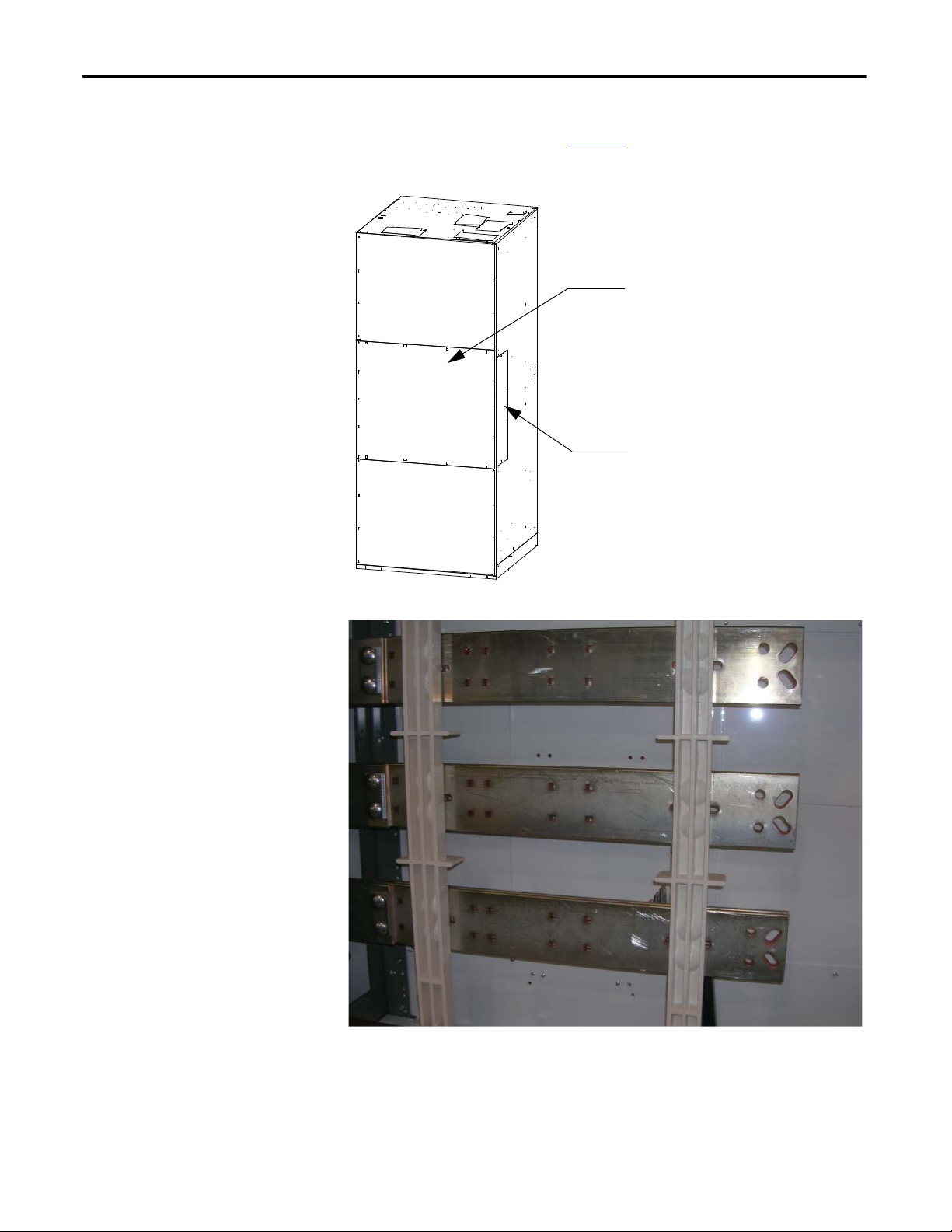
2. Open medium voltage power cell door (see Figure 29
Figure 29 - ArcShield Power Cell (Upper)
).
3. Remove the retaining screw from the cable duct barrier and remove the
barrier (see Figure 30
).
4. Remove the two retaining screws from the cable duct boot and remove the
boot (see Figure 30
).
28 Rockwell Automation Publication 1500-UM055G-EN-P - May 2013
Page 37

Installation – Arc-Resistant Enclosure (ArcShield) Chapter 3
Current Transformers
CT Mounting Plate
Loosen Retaining Screws
Cable Duct Boot
Remove Retaining Screws
Cable Duct Barrier
Remove Bus Access Cover
Figure 30 - Removing Cable Duct Boot and Barrier
5. To access the left side of the power bus, locate the two bus access covers at
the rear, left side of the power cell. Remove the four self-tapping screws
from each cover and remove the covers (see Figure 7 on page 10
Figure 31 - Removing Bus Access Covers
).
Rockwell Automation Publication 1500-UM055G-EN-P - May 2013 29
Page 38

Chapter 3 Installation – Arc-Resistant Enclosure (ArcShield)
Contactor Bus Bars
Mounting Bolts
Trailer Fuse Block
6. If access to the right side of the power bus is required, remove the vacuum
contactor from the upper power cell (refer to Removing the Contactor
page 52 of Chapter 5).
7. Remove the power fuses from the isolation switch.
8. Remove the interphase barriers from the trailer fuse block by raising them
vertically up and out of the mounting slots (see Figure 32
).
9. Use a 9/16-in. socket to remove the contactor bus bars from the isolation
switch trainer fuse block.
Figure 32 - Contactor Bus Bars (Trailer Fuse Block for Clip-on Fuses Shown)
on
10. Disconnect the secondary control wiring from the control power
transformer (CPT) and remove the CPT mounting plate. Leave the CPT
attached to the plate.
ATTENTION: The CPT is heavy and assistance may be required to safely
remove and transport the unit. Use caution when removing the CPT.
Failure to do so may result in personal injury and/or damage to the
equipment.
11. To access the right side of the power bus, remove the self-tapping screws
from the lower glass-polyester bus access cover and remove the cover (see
Figure 33
).
12. Reverse the procedure to reassemble the cabinet. Ensure that the barriers
are put back in place.
30 Rockwell Automation Publication 1500-UM055G-EN-P - May 2013
Page 39

Figure 33 - Access to Right Side of Power Bus
Remove self-
tapping screws
Cable Duct Barrier
Cable Duct Boo t
ATT EN TI ON : Ensure all barriers are replaced before re-energizing the
equipment. Failure to do so may result in electrical faults and cause damage to
equipment or serious injury to personnel.
Installation – Arc-Resistant Enclosure (ArcShield) Chapter 3
Front Access – Bottom Exiting Load Cables
If the cables in your cabinet exit from the bottom, the procedure to access the
power bus is almost identical to the one above. Follow the procedure for Front
Access - Top Exiting Load Cables, but remove the cable duct barrier and cable
duct boot from the top of the lower power cell, rather than those at the bottom
(see Figure 34
Figure 34 - Bottom Cable Exit Configuration
).
Rockwell Automation Publication 1500-UM055G-EN-P - May 2013 31
Page 40

Chapter 3 Installation – Arc-Resistant Enclosure (ArcShield)
IMPORTANT
IMPORTANT
Connect Load Cables to
Current Transformers
Removable Cable Duct Boot
to load cable conduit
opening for cables exiting
from bottom power cell
Load Cable Connections
ATT EN TI ON : To avoid shock hazards, lock out incoming power (refer to Power
Lock-out Procedure on page 47 of Chapter 5) before working on the equipment.
Verify with a hot stick or appropriate voltage measuring device that all circuits
are voltage free. Failure to do so may result in severe burns, injury or death.
The current transformers may be positioned for top or bottom cable exit.
Follow the appropriate procedure described for your starter configuration.
For ArcShield units, cable size should not exceed 1-500 MCM or 2-350 MCM
per phase.
Note: Refer to Dimensional Drawings provided with order documentation for
additional details related to cabinet floor plans.
1. Complete the Power Lock-out procedure (refer to Power Lock-out
Procedure on page 47 of Chapter 5).
2. Follow steps 2 to 6 from Front Access – Access to Power Bus
on page 28
for the procedure to swing out the low voltage panel.
3. Remove the cable duct boot at the top of the cabinet for top exiting load
cables, or remove the one at the bottom of the cabinet for bottom exiting
load cables (see Figure 35
).
Figure 35 - Access to Load Cable Conduit Openings (Bottom Exit Cable)
32 Rockwell Automation Publication 1500-UM055G-EN-P - May 2013
Page 41

Installation – Arc-Resistant Enclosure (ArcShield) Chapter 3
TIP
Top of Ca bin et
Load Cable Conduit Opening for
Cables from Top Power Cell
Load Cable Conduit
Opening for Cables from
Bottom Power Cell
Current Transformer
Mounting Plate
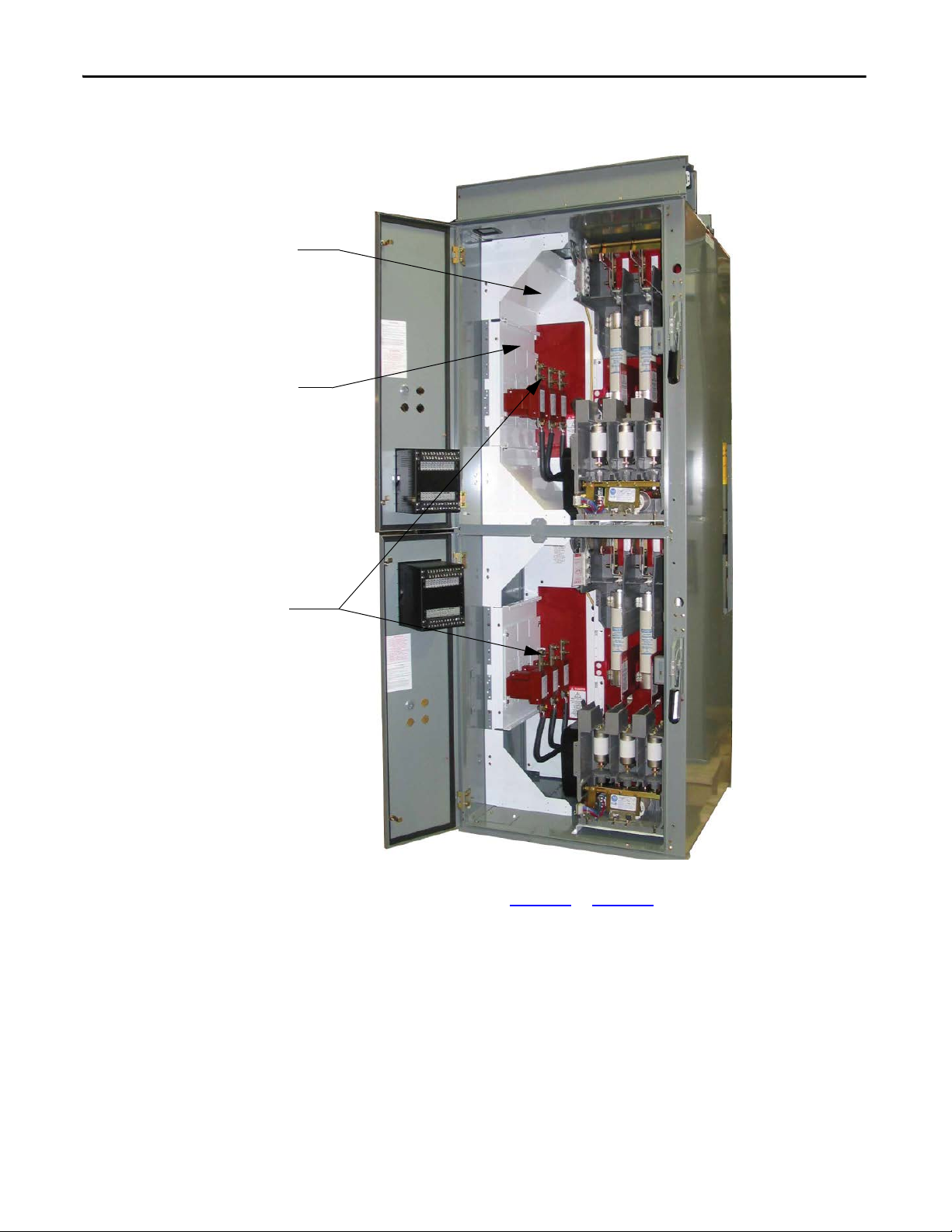
4. Remove the appropriate load cable conduit openings in the top or bottom
of the cabinet (see Figure 36
or Figure 37).
Top Exiting Load Cables
Follow steps 1-4 from previous section.
5. Load cables for the bottom power cell should be routed first. Pull the
cables into the cabinet through the appropriate opening (see Figure 36
Run the cables behind the current transformer mounting plate and into
the bottom power cell.
6. For the top power cell, pull the cables into the cabinet through the
appropriate opening (see Figure 36
Figure 36 - Load Cable Conduit Openings
).
).
7. Connect the cables to the current transformers and tighten the
connections to 65 N•m (48 lb•ft).
8. Connect cable shields to the ground lug.
9. Reinstall the cable duct boot and reassemble the cabinet.
ATTENTION: Ensure all barriers are replaced before re-energizing the
equipment. Failure to do so may result in electrical faults and cause
damage to equipment or serious injury to personnel.
Rockwell Automation Publication 1500-UM055G-EN-P - May 2013 33
Page 42

Chapter 3 Installation – Arc-Resistant Enclosure (ArcShield)
TIP
Load Cable Conduit Opening for
Cables f rom Top Power Cell
Load Cable Conduit Opening for
Cables from Bottom Power Cell
Bottom of Cabinet
Bottom Exiting Load Cables
Follow steps 1-4 from previous section.
5. Load cables for the top power cell should be routed first. Pull the cables
into the cabinet through the appropriate opening (see Figure 37
cables behind the current transformer mounting plate and into the top
power cell.
Figure 37 - Load Cable Conduit Openings
). Run the
6. For the bottom power cell, pull the cables into the cabinet through the
appropriate opening (see Figure 37
).
7. Connect the cables to the current transformers and tighten the
connections to 65 N•m (48 lb•ft).
8. Connect cable shields to the ground lug.
9. Reinstall the cable duct boot and reassemble the cabinet.
ATTENTION: Ensure all barriers are replaced before re-energizing the
equipment. Failure to do so may result in electrical faults and cause
damage to equipment or serious injury to personnel.
34 Rockwell Automation Publication 1500-UM055G-EN-P - May 2013
Page 43

Common Installation
IMPORTANT
IMPORTANT
IMPORTANT
Chapter 4
Bus Splicing
Power Bus
ATT EN TI ON : This procedure requires contact with medium voltage
components. To avoid shock hazards, lock out incoming power before working
on the equipment (refer to Power Lock-out Procedure
Verify with a hot stick or appropriate voltage measuring device that all circuits
are voltage free. Failure to do so may result in severe burns, injury or death.
1. The power and ground bus splice kit can be found in a package mounted
to the front of the shipping skid.
Verify that the structure series numbers on the splice kit package
match the structure series number found on the cabinet nameplate
(refer to Starter Identification
regarding the nameplate).
2. Refer to Access to the Power Bus
standard or ArcShield enclosure.
3. For a 1200A power bus, assemble the splice bars as shown in Figure 38
Tighten the nuts to 65 N•m (48 lb•ft).
For a 2000A power bus, assemble the splice bars as shown in Figure 39
Tighten the nuts to 65 N•m (48 lb•ft).
on page 26 of Chapter 3 for either
on page 2 of Chapter 1 for details
on page 47 of Chapter 5).
.
.
Attach the bus links to the cabinet on the left side first - as viewed from
the front of the unit.
Always place the bus clamps on the rear side of each main horizontal
bus or splice bar, as viewed from the front of the unit.
Rockwell Automation Publication 1500-UM055G-EN-P - May 2013 35
Page 44

Chapter 4 Common Installation
Bus Clamp
Flat Washer
Lock Washer
Hex Nut
Power Bus
Splice Bar
Bus Support
Main Horizontal
Power Bus
Bus Clamp
Flat Washer
Lock Washer
Hex Nut
Power Bus
Splice Bars
Bus Support
Main Horizontal
Power Bus
Figure 38 - Typical 1200A Power Bus Splicing Configuration (Viewed from front of cabinet)
Figure 39 - Typical 2000A Power Bus Splicing Configuration (Viewed from front of cabinet)
ATT EN TI ON : Ensure all barriers are replaced before re-energizing the
equipment. Failure to do so may result in electrical faults and cause damage to
equipment or severe injury to personnel.
Insulated Power Bus Splicing
If the starter is equipped with insulated power bus, then a splice kit with insulated
links, insulating boots and tape will be provided. Refer to the kit for installation
instructions.
36 Rockwell Automation Publication 1500-UM055G-EN-P - May 2013
Page 45

Common Installation Chapter 4
Ground Bus Support
Main
Ground
Bus
Hex Nut
Lock Wash er
Flat Washer
Ground Bus Splice Bar
IMPORTANT
Ground Bus
1. See Figure 40 to determine the correct ground splice configuration and
assemble as shown.
2. Torque the hardware to 15 N•m ± 1 N•m (12 lb•ft ± 1 lb•ft).
3. Check all hardware for correct tightness and replace all covers and plates.
Figure 40 - Typical Ground Bus Splicing Configuration (Front View)
Incoming Line Cable Connections
ATT EN TI ON : Ensure all barriers are replaced before re-energizing the
equipment. Failure to do so may result in electrical faults and cause damage to
equipment or severe injury to personnel.
ATT EN TI ON : To avoid shock hazards, lock out incoming power (refer to Power
Lock-out Procedure on page 47 of Chapter 5) before working on the equipment.
Verify with a hot stick or appropriate voltage measuring device that all circuits
are voltage free. Failure to do so may result in severe burns, injury or death.
Incoming cables are connected to the power bus in the last section on the left.
For Non-ArcShield units, cable size should not exceed 1-750 MCM or
2-500 MCM per phase.
For ArcShield units, cable size should not exceed 1-500 MCM or 2-4/0 per
phase. For larger cables, an incoming line module must be used.
1. Remove the center-back plate or side plate to access the power bus. If access
to the rear of the unit is not possible, refer to Access to the Power Bus
on
page 9 of Chapter 2 for either standard or ArcShield enclosures.
2. Connect the incoming power lines to the power bus. Torque to
specifications (refer to Recommended Torque Values
Chapter 1) (see Figure 41).
on page 3 of
Rockwell Automation Publication 1500-UM055G-EN-P - May 2013 37
Page 46

Chapter 4 Common Installation
Power
Cable
Lugs
Ground
Bus
Lug
IMPORTANT
Figure 41 - Incoming Line Cable Connections
If line cables require installation by front access, complete the incoming line
connection before installing load cables.
3. Connect the ground wire to the ground bus lug.
4. Connect any external control wires to the control panel terminal blocks in
the low voltage compartment. Refer to wiring diagram.
38 Rockwell Automation Publication 1500-UM055G-EN-P - May 2013
Page 47

Common Installation Chapter 4
Current Barrier Transformer
Installation of Current Transformer Barrier
Figure 42 - Current Transformer Barrier
Hi-Pot and Megger Test
ATT EN TI ON : Ensure current transformer barrier is installed before
re-energizing the equipment. Failure to do so may result in electrical faults and
cause damage to equipment or serious injury to personnel.
Insulation integrity should be checked before energizing medium voltage
electrical equipment. Use a high voltage AC insulation tester or a Megger for this
test. If a Megger is used, a 5000 volt type is recommended.
ATT EN TI ON : Exercise caution when performing high voltage tests on the
equipment. Failure to do so may result in electric shock causing severe burns,
injury or death
ATT EN TI ON : Disconnect power factor correction capacitors (if so equipped)
before performing the Hi-Pot test. Failure to do so may result in personal injury
or damage to the equipment. See Power Lock-out Procedure (refer to Po wer
Lock-out Procedure on page 47 of Chapter 5) for information on dissipating any
stored power in the capacitors.
Rockwell Automation Publication 1500-UM055G-EN-P - May 2013 39
Page 48

Chapter 4 Common Installation
ATT EN TI ON : Remove all primary fuses for the control power transformer and/
or the potential transformer. Failure to do so may cause damage to the
equipment during the Hi-Pot test.
Insulation can be tested from phase to phase and from phase to ground. The
recommended level for AC Hi-Pot testing is (2 X V
rated line-to-line voltage of the power system. The leakage current must be less
than 20 mA. Record the result for future comparison testing.
If a Megger is used, it should indicate 50,000 megohms or greater if the unit is
isolated from the line and the motor. If the unit is connected to a motor, the
Megger should indicate 5,000 megohms or greater (phase to ground).
) volts, where VLL is the
LL
Start-up Procedure
Contactor Inspection
See Publication 1502-UM050_-EN-P or 1502-UM052_EN-P for information on
pre-energization inspection, vacuum bottle integrity test and insulation resistance test.
Preliminary Checks
Ver if y t he fo llo wi ng :
• Contactor current and voltage ratings are correct for the attached load;
• Control voltage is correct;
• Settings for protective relays;
• Heater elements (if provided) in overload relay are secure and undamaged;
• Equipment grounding;
• External power and control connections match electrical diagrams;
• All hardware is correctly reinstalled and torqued to specifications (refer
to Recommended Torque Values
• All barriers are replaced to correct positions;
• All fuses are correct class, type and rating;
• Mechanical interlocks and isolation switch function properly;
• Ensure that any microprocessor-based protection relay is programmed;
• Interior of cabinet is free from dirt, loose bolts, tools or metal chips.
Vacuum clean if necessary;
• All tools are accounted for. If you cannot locate a tool, do not energize the
unit until it is found.
on page 3 of Chapter 1);
40 Rockwell Automation Publication 1500-UM055G-EN-P - May 2013
Page 49

Common Installation Chapter 4
Testing Contactor Operation
1. Connect the appropriate external power supply (120 or 230V AC) to the
test receptacle in the control panel. Turn the selector switch to the TEST
position.
ATTENTION: Some control circuit configurations may require control
jumpers to let the contactor close during the test procedure. Do not
jumper any isolation switch contacts such as ISa or ISb (see Figure 66 on
page 65 for the location of these contacts). Using jumpers for these
contacts may result in equipment damage or injury to personnel.
2. Electrically operate the contactor several times. Inspect the armature plate
to verify that it fully contacts the magnetic cores.
3. Turn the selector switch to the OFF position and unplug the test voltage.
4. Remove any metal filings or loose hardware from around the magnetic
cores of the vacuum contactor. The debris is attracted to the coil once it is
energized and could prevent the contactor from closing properly.
Rockwell Automation Publication 1500-UM055G-EN-P - May 2013 41
Page 50

Chapter 4 Common Installation
L1 L3L2 GRD
MTR
ISOLATING SWITCH
DOOR INTERLOCK
CURRENT LIMITING
POWER FUSES
TEST SUPPLY POINT
X
X
PRIMARY FUSES
CURRENT LIMITING
V
VA
V
50/60Hz
OVERLOAD
592
REMOTE EQUIPMENT
"IEEE" NUMBER FOR PROTECTIVE DEVICE
LOW VOLTAGE DOOR MOUNTED DEVICED
CUSTOMER WIRING
LEGEND
2400V-6900V,3Ø, 50/60Hz
EXTRA AUXILIARY
CONTACTS
YBLK
HC
B Y
MOV
CC
-
+
CC-CLOSING COIL
HC-HOLDING COIL
MAIN CONTACTOR
PILOT RELAY (CR1)
STOP
DSTART
D
D
D
RUN
OFF
MAIN
CONTACTOR (M)
ECONOMIZING
CONTACTOR (CR2)
37
KML
36
33
HM32G
1
3534
1
IJM
31
MF
30
E
1
OL
4
3
CR1
21A
CR2
12
20
M
17C
19
17A15A 17B15
MOV
N
13
17
MAB
CR1
REC/MOV
CR2CR1 CR2 CR2CR1
M
CR2 DC
(1) (2)
(3) (4)
NORMAL
OFF
TEST
X
X
47
46
44
42
OL
49
120V
TS
F3
__EF2__EF2
____
120
500
CPT
M
(6) (5)
(7) (8)
12
ISa
5
IS
T2
T1
CT2
CT1
T3
CT3
12
11
6
10
F1
F1
F1
78
9
ISb
REMOVE JUMPER WHEN CONNECTING REMOTE EQUIPMENT
Typical Wiring Diagrams
Figure 43 - Typical Wiring Diagram: Electrically Held Vacuum Contactor (Relay Control)
42 Rockwell Automation Publication 1500-UM055G-EN-P - May 2013
Page 51

Common Installation Chapter 4
L1 L3L2 GRD
MTR
ISOLATING SWITCH
DOOR INTERLOCK
CURRENT LIMITING
POWER FUSES
TEST SUPPLY POINT
X
X
PRIMARY FUSES
CURRENT LIMITING
V
VA
V
OVERLOAD
592
REMOTE EQUIPMENT
"IEEE" NUMBER FOR PROTECTIVE DEVICE
LOW VOLTAGE DOOR MOUNTED DEVICE
D
CUSTOMER WIRING
LEGEND
2400V-6900V,3Ø, 50/60Hz
INTELLIVAC TO BE PROGRAMMED/CONFIGURED BY THE
POWER APPLIED. THE FOLLOWING FACTORY INSTALLED
OUTPUT RELAY CONTACTS SHOWN WITHOUT CONTROL
MODULE STATUS - FAIL SAFE
CONTACTOR STATUS - FAIL SAFE
CUSTOMER BEFORE START-UP.
CONFIGURATION/POWER-UP STATES ARE IN EFFECT:
INTELLIVAC NOTES:V
- INTELLIVAC MODULE VACUUM CONTACTOR AUXILIARY INPUTAUX
- INTELLIVAC MODULE EXTERNAL CAPACITOR INPUTEC
- INTELLIVAC MODULE CLOSING COIL OUTPUTCCO
- MAIN CONTACTOR INTELLIVAC MODULEM-IV
- INTELLIVAC MODULE TRIP COIL OUTPUTTCO
REMOVE JUMPER WHEN CONNECTING REMOTE EQUIPMENT
EXTRA AUXILIARY
CONTACTS
MOV
32
1
EC
-
+
4
TCO
12
11
AUX CCO
5
6
L1
G
+-
V
V
STOP
DSTART
D
V
D
D
RUN
OFF
MAIN
CONTACTOR (M)
37
KML
36
33
HM32G
3534
1
IJM
31
MF
30
E
1
OL
4
M-IV
15 16
CONTACTOR
STATUS
321A
14
M-IV
910
CLOSE
12
14A
F7
2.0A
171315
20
ABM
M-IV
M
M
NC
1
12
(1) (2)
(3) (4)
NORMAL
OFF
TEST
X
X
47
46
44
42
OL
49
TS
F3
__EF2__EF2
____
120
500
CPT1
M
(6) (5)
(7) (8)
12
ISa
5
IS
T2
T1
CT2
CT1
T3
CT3
11
6
10
F1
F1
F1
78
9
ISb
50/60Hz120V
Figure 44 - Typical Wiring Diagram: Electrically Held Vacuum Contactor (with IntelliVAC Control)
Rockwell Automation Publication 1500-UM055G-EN-P - May 2013 43
Page 52

Chapter 4 Common Installation
Notes:
44 Rockwell Automation Publication 1500-UM055G-EN-P - May 2013
Page 53

Maintenance
IMPORTANT
IMPORTANT
ATT EN TI ON : Use suitable personal protective equipment (PPE) per local codes
or regulations. Failure to do so may result in severe burns, injury or death.
Establish a maintenance and inspection schedule for the equipment. Annual
servicing, or every 20,000 operations (whichever comes sooner) is the
minimum recommended. Extreme operating conditions may warrant
additional attention.
Chapter 5
Tool Requirements
Recommended Torque Values
Some components of this product incorporate Imperial hardware. Rockwell
Automation recommends the use of the appropriate tools to successfully
complete the maintenance procedures on these components. If you cannot
obtain such tools, contact your area Rockwell Automation sales office for
assistance.
• Torque wrench: 0...65 N•m (0...48 lb•ft)
• Sockets: 3/8 in., 7/16 in., 9/16 in., 3/4 in. and 7/8 in.
• Ratchet handle and extension
• Wrenches: 7/16 in., 1/2 in., 9/16 in., 3/4 in. and 7/8 in.
• Feeler gauges: 1.3 mm (0.050 in.), 2 mm (0.080 in.), 0.5 mm (0.020 in.)
• Flat-blade screwdriver
• Nyogel 759G Lubricant, Rockwell Automation part no. 80158-357-51
When reinstalling components, or when reassembling the cabinet, tighten the
following bolt sizes to the specified torque values:
Table 2 - Hardware Torque Values
1/4 in. hardware 8 N•m (6 lb•ft)
5/16 in . hardware 15 N•m ( 12 lb•ft)
3/8 in. hardware 27 N•m (20 lb•ft)
1/2 in. hardware 65 N•m (48 lb•ft)
Rockwell Automation Publication 1500-UM055G-EN-P - May 2013 45
Page 54

Chapter 5 Maintenance
Door Interlock Lever
Door Interlock Circumvention
ATT EN TI ON : The door interlock mechanism is designed to prevent access to the
medium voltage cell while the unit is energized. When the unit is in operation,
do not circumvent this interlocking safety feature. Always disconnect and lock
out incoming power (refer to Power Lock-out Procedure
on page 47) before
proceeding with any adjustments requiring the handle to be moved to the ON
(closed) position. Failure to do so may result in electric shock causing severe
burns, injury or death.
Some of the following sections may require moving the isolation switch handle to
the ON position while the medium voltage door is open. The interlocking
safeguards in the mechanism are designed to prevent the handle from moving to
the ON position while the cabinet door is open.
• To circumvent this safety feature, use a screwdriver, or other tool, to
depress the door interlock lever in a downward movement.
• Hold the lever down while moving the handle to the ON (closed)
position.
Figure 45 - Door Interlock Lever
ATT EN TI ON : Use suitable personal protective equipment (PPE) per local codes
or regulations. Failure to do so may result in severe burns, injury or death.
46 Rockwell Automation Publication 1500-UM055G-EN-P - May 2013
Page 55

Maintenance Chapter 5
Control Switch
Auxiliary Power
Receptacle
ATT EN TI ON : Always perform the Power Lock-out procedure before servicing
the equipment. Failure to do so may result in severe burns, injury or death.
Power Lock-out Procedure
ATT EN TI ON : The following procedure requires moving the isolation switch
handle to the ON position. To avoid shock hazards, disconnect and lock out
incoming power before proceeding with servicing the equipment.
Failure to lock out incoming power will result in a live power cell once the isolation
switch handle is in the ON position and may cause severe burns, injury or death.
Rockwell Automation does not assume any responsibility for injuries to personnel
who have not completed the following safety procedure prior to servicing the
equipment.
1. Disconnect and lock out all feeder power supplies to the starter.
2. Move the isolation switch handle to the OFF position.
3. If the unit is equipped with power factor correction capacitors, stored
energy must be dissipated before entering the power cell. Wait at least five
minutes before entering the power cell or dissipate the power using the
following procedure:
a. Verify that the isolation switch handle is in the OFF position.
b. Open the low voltage door.
c. Connect the appropriate power supply (120 or 230V ) into the auxiliary
control power circuit as shown on the electrical drawing (see
Figure 46
).
d. Move the control switch to the TEST position.
Figure 46 - Control Panel (IntelliVAC Control)
Rockwell Automation Publication 1500-UM055G-EN-P - May 2013 47
Page 56

Chapter 5 Maintenance
See Detail A
Grounding Bar
Isolation Switch Blades
must fully engage
Grounding Pins of
Grounding bar
(Verify for each phase)
Isolation Switch Shutters
must be closed
(Verify for each phase)
Detail A
Grounding Pins
Isolation Switch
Blades in open
position
Viewed from back with components
removed for clarifica tion
e. Electrically operate the contactor by pushing the START button on the
unit or at a remote location.
f. Disengage the contactor and move the control switch to the OFF
position. Disconnect the external power supply.
g. Complete the Power Lock-out procedure
4. Open the medium voltage door.
5. Visually inspect that the isolation switch blades fully engage the grounding
pins on the grounding bar. The isolation switch shutters should be closed
(see Figure 47
Figure 47 - Inspecting Isolation Switch in Open Position
).
48 Rockwell Automation Publication 1500-UM055G-EN-P - May 2013
Page 57

Maintenance Chapter 5
Check line-side power here
Check load-side power here
Isolation Switch Blades must
fully engage Incoming Line Stabs
Check incoming line voltage here
6. Check the line and load sides of the contactor with a hot stick or
appropriate voltage measuring device for the system voltage, to verify that
they are voltage free (see Figure 48
).
a. Check for line-side voltage at the top vacuum bottle terminals.
b. Check for load-side voltage at the bottom vacuum bottle terminals.
Figure 48 - Contactor Voltage Checkpoints
7. Use the Door Interlock Circumvention procedure (refer to Door Interlock
Circumvention on page 46) to move the isolation switch handle to the
ON position.
8. Check the isolation switch blades with a hot stick or appropriate voltage
measuring device for the system voltage, to verify that they are voltage free
(see Figure 49
Figure 49 - Isolation Switch Voltage Check Points
).
9. Once all power circuits are verified to be voltage free, move the isolation
switch handle back to the OFF position. The unit is now safe to service.
Rockwell Automation Publication 1500-UM055G-EN-P - May 2013 49
Page 58

Chapter 5 Maintenance
Bolt-on Fuses
Clip-on Fuse
Clip-on Fuse Ex tractor
Fuse Removal and Replacement
ATT EN TI ON : Only personnel who have been trained and understand the
Bulletin 1500 product line are to work on this equipment. Suitable safety
equipment and procedures are to be used at all times.
Figure 50 - Medium Voltage Power Fuses
ATT EN TI ON : Servicing energized industrial control equipment can be
hazardous. Severe injury or death can result from electrical shock, burn, or
unintended actuation of control equipment. Hazardous voltages may exist in
the cabinet even with the circuit breaker in the OFF position. Recommended
practice is to disconnect or lock out control equipment from power sources, and
confirm discharge of stored energy in capacitors. If it is necessary to work in the
vicinity of energized equipment, the safety related work practices of NFPA 70E,
Electrical Safety requirements for Employee Work places, must be followed.
ATT EN TI ON : To prevent electrical shock, ensure the main power has been
disconnected and equipment has been tagged and locked out. Verify that all
circuits are voltage free using a hot stick or appropriate voltage-measuring
device. Failure to do so may result in injury or death.
50 Rockwell Automation Publication 1500-UM055G-EN-P - May 2013
Page 59

Maintenance Chapter 5
TIP
TIP
TIP
The main power fuse has a pop up indicator pin located at one end of the fuse.
When a fuse has opened, the indicator will be in its extended position. The fuse
should be oriented in the fuse clip assembly so that the indicator is at the top.
ATT EN TI ON : The fuses may be hot for up to one hour after operating. Verify the
temperature before handling and use insulated hand protection if needed.
Failure to do so may result in burns.
Bolt-on Fuse Removal/Installation
To ol s r eq ui re d: 3/8-in. drive ratchet, 2-in. extension, 6-in. extension, 12-in.
extension, 1/2-in. socket, 3/8-in. drive torque wrench.
The fuse configuration will determine what length of extension will be
required to get at the mounting hardware. The fuse configuration will also
determine what size of interphase barriers are installed, the lower barriers can
be removed to provide better access to the fuse mounting nuts.
1. Remove the two lower mounting nuts, lock and flat washers from the
mounting studs.
2. Remove the upper two mounting nuts, lock and flat washers from the
mounting studs and remove the fuse from the fuse mounting studs.
3. Install the replacement fuse on the four mounting studs, hold the fuse in
place and install the upper two flat washers, lock washers and nuts. Torque
nuts to 15 N•m (12 lb•ft).
4. Install the lower two flat washers, lock washers and nuts. Torque nuts to
15 N•m (12 lb•ft).
5. If interphase barriers were previously removed ensure they are properly
reinstalled.
Clip-on Fuse Removal/Installation
Recommended tool: Fuse extractor part # 80144-491-02 (optional)
The interphase barriers located at the bottom of the fuse assembly can be
removed to ease the removal and installation of the fuse.
1. Place the cup section of the fuse extractor over the top of the fuse.
2. Pull back on fuse extractor with a quick motion to dislodge the upper
portion of the fuse from top fuse clip.
3. Set fuse extractor aside.
4. Remove the lower portion of the fuse from fuse clip by pulling up and
slightly rotating the fuse in one entire movement.
5. To install the replacement fuse, place the fuse between the fuse clips.
Rockwell Automation Publication 1500-UM055G-EN-P - May 2013 51
Page 60

Chapter 5 Maintenance
Flares
Blown Fuse Indicator
(shown in blown state)
6. Ensure that the flares on the fuse ferrules are properly located with respect
to the fuse clips.
7. Apply a rapid shove to the bottom portion of the fuse barrel to force the
fuse into the clip.
8. Apply a rapid shove to the top portion of the fuse barrel to force the fuse
into the clip.
9. Grip center of fuse barrel with both hands and apply slight back and
forward force to ensure fuse has been properly seated in the fuse clips.
10. Again check and verify that the flares at the top and bottom of the fuse are
not in the contact area of the fuse clip.
11. If interphase barriers were previously removed ensure they are properly
reinstalled.
Figure 51 - Clip-on Style Medium Voltage Power Fuse
Contactor Maintenance
Refer to publication 1502-UM050_-EN-P or 1502-UM052_-EN-P for
contactor maintenance instructions.
Removing the Contactor
ATT EN TI ON : To avoid shock hazards, lock out incoming power (refer to Power
Lock-out Procedure on page 47) before working on the equipment. Verify with a
hot stick or appropriate voltage measuring device that all circuits are voltage
free. Failure to do so may result in severe burns, injury or death.
1. Complete the Power Lock-out Procedure (refer to Power Lock-out
Procedure on page 47).
2. Disconnect the control wiring harness from the wire plug at the lower left
side of the contactor (See Figure 52
3. Remove the control power transformer primary fuses from the top of the
contactor.
52 Rockwell Automation Publication 1500-UM055G-EN-P - May 2013
)
Page 61

Maintenance Chapter 5
Contac tor
Operating Level
Contac tor
Interlock Rod
Contactor Interlock Rod
Nylon Contactor
Bushing
Retaining Screw
Nylon
Contactor
Bushing
Nyloc Nut
Contactor Operating Lever
Contactor
Remaining Tabs
4. Disconnect the control power transformer primary leads from the fuse
terminals at the top of the contactor.
5. Use a 9/16-in. socket wrench to disconnect the power cables and bus bars
from the rear of the contactor.
6. Remove the nylon contactor bushing retaining screw from the contactor
interlock lever.
7. Slide the contactor interlock rod and the nylon contactor bushing out of
the groove in the contactor interlock lever (see Figure 53
Figure 52 - Removing the Contactor (Front view)
).
Figure 53 - Removing the Contactor (Right-side view)
8. Remove the two contactor mounting bolts at the front of the contactor.
Rockwell Automation Publication 1500-UM055G-EN-P - May 2013 53
Page 62

Chapter 5 Maintenance
9. Slide the contactor forward slightly to disengage the retaining tabs at the
rear of the contactor from the mounting bracket inside the cabinet.
10. Carefully remove the contactor from the cabinet.
ATT EN TI ON : The contactor weighs approximately 22 kg (50 lbs) and assistance
may be required to safely remove it from the cabinet and transport it. Failure to
use caution when moving the contactor may result in equipment damage
and/or personal injury.
11. If the contactor is being replaced with a new one, move the contactor
interlock lever to the new contactor.
ATT EN TI ON : The retaining screw is critical to the mechanical integrity of the
isolation switch. It is very important to ensure this screw is replaced during
reassembly.
12. Reverse the procedure to reinstall the contactor. Ensure the mounting
bolts, power cable hardware and bus bar hardware is properly torqued
(refer to Recommended Torque Values
on page 3 of Chapter 1).
Contactor Interlock Rod Adjustment
13. Adjust the contactor interlock rod according to the Contactor Interlock
Rod Adjustment procedure (refer to Contactor Interlock Rod Adjustment
on page 54).
ATT EN TI ON : To avoid shock hazards, lock out incoming power (refer to Power
Lock-out Procedure on page 47) before working on the equipment. Verify with a
hot stick or appropriate voltage measuring device that all circuits are voltage
free. Failure to do so may result in severe burns, injury or death.
1. Complete the Power Lock-out Procedure (refer to Power Lock-out
Procedure on page 47).
2. Open the medium voltage door. Use the Door Interlock Circumvention
procedure (refer to Door Interlock Circumvention
the isolation switch handle halfway between the OFF and ON position
(see Figure 54
procedure is completed.
3. With the contactor in the OFF position, insert a 1.5 mm (0.060 in.) feeler
gauge in the gap between the interlock lever and the isolation switch
operating lever. The gap must be between 1.0 mm to 2.0 mm (0.039 in. to
0.078 in.).
). Keep the handle in this position until the adjustment
on page 46) to move
4. To reduce the gap distance, follow steps 5-7.
To increase the gap distance follow steps 8-10.
54 Rockwell Automation Publication 1500-UM055G-EN-P - May 2013
Page 63

Figure 54 - Isolation Switch Handle Adjustments
Isolation Switch
Operating Lever
Isolation Switch
Handle at halfway
position
Nyloc Nut
Contactor Interlock Lever
Contactor Interlock Rod
Stop Bracket
Switch Interloc k Lever
Gap: 0.045...0.060 in.
(1.1...1.5 mm)
Maintenance Chapter 5
To Reduce the Gap Distance
To Increase the Gap Distance
5. Loosen the two screws in the stop bracket and move the stop bracket up
against the interlock lever.
6. With the feeler gauge positioned in the gap, move the interlock lever and
the stop bracket closer to the isolation switch operating lever to reduce the
gap space. Tighten the stop bracket screws.
7. Tighten the nyloc nut until it is snug against the contactor interlock lever.
Do not overtighten the nyloc nut as it will move the interlock lever and
reduce the gap. Proceed to Step 11.
8. Loosen the two screws in the stop bracket and move the stop bracket away
from the interlock lever.
9. Loosen the nyloc nut until the gap reaches the desired size.
Rockwell Automation Publication 1500-UM055G-EN-P - May 2013 55
Page 64

Chapter 5 Maintenance
Contac tor
Interlock Rod
Contac tor Plug
Contac tor
Mounting Bolts
Contactor
Operating Lever
10. Move the stop bracket until it just touches the interlock lever and tighten
the screws.
11. Apply Loctite 290 (or equivalent adhesive) to the stop bracket screws and
torque the screws to 8 N•m (6 lb•ft).
12. Move the isolation switch handle to the ON position.
13. Manually close the contactor by attaching locking pliers to the contactor
interlock lever and pushing down until the armature plate contacts the
magnetic cores (see Figure 55
). Verify that the interlock lever overlaps the
isolation switch operating lever by at least 3 mm (0.125 in.) (see
Figure 56
Figure 55 - Closing Contactor Manually (Some parts not shown)
).
56 Rockwell Automation Publication 1500-UM055G-EN-P - May 2013
Page 65

Maintenance Chapter 5
Overlap minimum
0.125 in. (3 mm)
Isolation
Switch
Operating
Lever
Interlock Lever
Figure 56 - Isolation Switch Operating Lever Overlap
14. Open the contactor. Verify that the interlock lever and the rod move freely
and that the return springs move the assembly back to the starting
position.
Isolation Switch Mechanism Inspection and Lubrication
ATT EN TI ON : To avoid shock hazards, lock out incoming power (refer to Power
Lock-out Procedure on page 47) before working on the equipment. Verify with a
hot stick or appropriate voltage measuring device that all circuits are voltage
free. Failure to do so may result in severe burns, injury or death.
1. Complete the Power Lock-out Procedure (refer to Power Lock-out
Procedure on page 47).
2. Open the medium voltage door.
3. Inspect the condition of the clevis pin and cotter pins shown in Figure 57
Replace any worn parts.
4. If it is necessary to replace the isolation switch operating lever or the
interlock lever, apply Dow Corning 55 O-ring lubricant (Rockwell
Automation part no. RU-8216, or equivalent) to the pivot points before
installing the new components (see Figure 57
).
.
Rockwell Automation Publication 1500-UM055G-EN-P - May 2013 57
Page 66

Chapter 5 Maintenance
Contactor Interlock Rod
Lubrication Points
(at replacement only)
Interlock Lever
Clevis Pins and Cotter Pins
Threaded Connecting Rod
Isolation Switch
Operating Lever
IMPORTANT
IMPORTANT
Figure 57 - Isolation Switch Handle Mechanism Lubrication Points
5. Inspect the mounting hardware on the isolation switch operating lever and
contactor interlock rod (see Figure 57
6. Inspect the isolation switch blades and the incoming line stabs (see
Figure 63
7. Remove any dirt and dried grease.
8. Lubricate the isolation switch blades and the isolation switch blade pivot
points with Nyogel 759G (see Figure 58
). Tighten any loose hardware.
). The mating surfaces must be clean and well lubricated.
Do not scrape or file the parts. This may remove the plating and expose
the underlying copper to corrosion.
).
Lubricate the isolation switch blades a minimum of once per year to
avoid excessive wear to the components and to prevent the isolation
switch blades from overheating.
58 Rockwell Automation Publication 1500-UM055G-EN-P - May 2013
Page 67

Figure 58 - Isolation Switch Lubrication Points
Lubricate Isolation
Switch Blades
Lubricate Pivot
Point s
Maintenance Chapter 5
Isolation Blade Switch Adjustment
The Bulletin 1500 (Series R) Isolation Switch has been updated to improve
performance. This procedure ensures the isolation switch linkage assembly
operates correctly with the new design change.
ATT EN TI ON : Complete the Power Lockout procedure of the main power bus
before servicing equipment. Verify with a hot stick or appropriate voltage
measuring device that all circuits are voltage free. Failure to do so may result in
severe burns, injury, or death.
WARNING: Use suitable personal protective equipment (PPE) per local codes or
regulations. Failure to do so may result in severe burns, injury, or death.
1. Insert a screwdriver in the Isolation Switch Defeater, push down and hold
at the bottom position.
2. Actuate the Isolation Switch Operating Handle from Open (black) to
Closed (red) in a continuous movement.
Do not use excessive force or speed in closing the switch. This will cause an
incorrect test result.
Rockwell Automation Publication 1500-UM055G-EN-P - May 2013 59
Page 68

Chapter 5 Maintenance
Closed position
Open position
Isolation Switch
Operating
Handle
Isolation
Switch
Defeater
Isolation Switch Linkage
Assembly (Phase 3)
TIP
Figure 59 - Isolation Switch Defeater
3. Phase 3 (far right linkage) must be measured for overall travel.
All three phases share the same main actuating shaft but the Phase 3 is the
easiest to measure.
Figure 60 - Isolation Switch Linkage Assembly Location
4. Rest the customer-supplied digital protractor on the bottom of the
isolation switch linkage assembly.
The angle of the linkage must be 180º or slightly higher, with a tolerance
of
0/+6 degrees.
If a digital protractor is unavailable, lay a straight edge against the
bottom of the steel lever on the operating shaft to check for parallel
alignment of the red link.
60 Rockwell Automation Publication 1500-UM055G-EN-P - May 2013
Page 69

Figure 61 - Isolation Switch Linkage Assembly Angle Location
Must have
tolerance of
0/+6
degrees
Shaft Assembly
Red Glass
Polye ster
Switch Link
Isolation Switch
Mechanical
Threaded Linkage
Maintenance Chapter 5
5. Loosen the lock nuts at each clevis (Note: one is a left-handed thread).
6. Adjust the isolation switch mechanical threaded linkage with a wrench
until the overall travel angle of the switch link is within the required
tolerance.
7. Hold the position of the threaded linkage and tighten the lock nuts.
Figure 62 - Isolation Switch Mechanical Threaded Linkage
Rockwell Automation Publication 1500-UM055G-EN-P - May 2013 61
Page 70

Chapter 5 Maintenance
Ground Bar
Maximum Gap 0.06 in. (1.5 mm) between ground
Bar and Isolation Switch in open position
Isolation Switch Blade
Incoming Line Stab
Auxiliary Contact
8. Actuate the Isolation Switch handle to verify the travel angle.
If the angle is incorrect, repeat steps 5 through 7 until desired travel angle is
reached.
ATT EN TI ON : All three isolation switch linkage assemblies must meet the angle
tolerance requirements.
Isolation Switch Mechanism Grounding Adjustment
ATT EN TI ON : To avoid shock hazards, lock out incoming power (refer to Power
Lock-out Procedure on page 47) before working on the equipment. Verify with a
hot stick or other appropriate voltage measuring device that all circuits are
voltage free. Failure to do so may result in severe burns, injury or death.
1. Complete the Power Lock-out Procedure (refer to Power Lock-out
Procedure on page 47).
2. Inspect the grounding of the isolation switch blades. When the isolation
switch handle is in the OFF position, the isolation switch blades must fully
engage the grounding pins and be within 1.5 mm (0.06 in.) of the ground
bar (see Figure 63
). When the isolation switch handle is in the ON
position, the blades must fully engage the incoming line stabs.
Figure 63 - Isolation Switch Grounding Adjustment
62 Rockwell Automation Publication 1500-UM055G-EN-P - May 2013
Page 71

Maintenance Chapter 5
CATALOG NO.
700-CPM
SER. A
20
AMP
CATALOG NO.
700-CPM
SER. A
20
AMP
CATALOG NO.
700-CPM
SER. A
20
AMP
CATALOG NO.
700-CPM
SER. A
20
AMP
CATALOG NO.
700-CPM
SER. A
20
AMP
CATALOG NO.
700-CPM
SER. A
20
AMP
D-head Fastener
Correct
Incorrect
3. To adjust the distance from the blades to the bar, disconnect the threaded
connecting rod at the handle operating lever (see Figure 57
4. Turn the threaded connecting rod to lengthen or shorten it. This will
adjust the position of the isolation switch blades in the ON and OFF
position.
).
Auxiliary Contacts Inspection and Replacement
ATT EN TI ON : To avoid shock hazard, lock out incoming power (refer to Power
Lock-out Procedure on page 47) before working on the equipment. Verify with a
hot stick or appropriate voltage measuring device that all circuits are voltage
free. Failure to do so may result in severe burns, injury or death.
1. Complete the Power Lock-out Procedure (refer to Power Lock-out
Procedure on page 47).
2. Inspect the auxiliary contacts for wear, scorching or heat damage. Replace
any damaged contacts. The contacts have a mean time between failure
(MTBF) rating of 20 million operations if used within the operating
specifications.
3. To remove the contact, turn both of the D-head fasteners until the flat
sections are aligned with the edge of the contact (see Figure 64
4. Remove the contact from the housing.
5. Disconnect the wires from the auxiliary contact.
6. Reverse the procedure to replace the auxiliary contact.
7. Ensure the contact is correctly positioned into the contact carrier (see
Figure 64
Figure 64 - Auxiliary Contact Orientation
).
).
Rockwell Automation Publication 1500-UM055G-EN-P - May 2013 63
Page 72

Chapter 5 Maintenance
ISa Auxiliary
Contacts (N.O.)
ISb Auxiliary Contacts (N.C.)
IMPORTANT
Isolation Switch Auxiliary Contacts
The auxiliary contacts are mounted on the left side of the isolation switch,
slightly below the cams on the isolation switch shaft.
Normally open contacts (Isolation Switch a Contacts - ISa) are on the outside of
the isolation switch housing, and normally closed contacts (Isolation Switch b
Contacts - ISb) are on the inside of the housing.
Figure 65 - Location of ISa and ISb Auxiliary Contacts
ISa and ISb contacts are exactly the same (700 CPM). The cam controls the
normally open or normally closed status of the contacts.
Refer to Figure 43 on page 42
The Isolation Switch Ground Adjustment procedure (refer to Isolation Switch
Mechanism Grounding Adjustment on page 62) must be completed before
adjusting the auxiliary contacts to ensure proper synchronization of the
assembly.
to Figure 44 on page 43 for wiring diagrams.
Adjusting the Normally Open (ISa) Contacts
ATT EN TI ON : To avoid shock hazards, lock out incoming power (refer to Power
Lock-out Procedure on page 47) before working on the equipment. Verify with a
hot stick appropriate voltage measuring device that all circuits are voltage free.
Failure to do so may result in severe burns, injury or death.
1. Move the isolation switch handle to the OFF (open) position.
2. Loosen the bolt holding the outside cam to the shaft. Do not loosen the
bolt entirely. The cam should not be able to rotate freely on the shaft.
3. Move the isolation switch handle to the ON (closed) position and check
that nothing prevents cam from rotating with the shaft.
64 Rockwell Automation Publication 1500-UM055G-EN-P - May 2013
Page 73

Maintenance Chapter 5
CATALOG NO.
700-CPM
SER. A
20
AMP
Cam
Cam Follower
Auxiliary Contact
Gap: 0.25 in. (6.35 mm)
4. Insert a 6.35 mm (0.25 in.) diameter pin into the cam groove between the
cam follower and the end of the cam groove.
Figure 66 - Adjusting Auxiliary Contacts (ISa Auxiliary Contact Shown)
5. Adjust the cam on the shaft so that the gap from the cam follower to the
end of the cam groove is the width of the pin – 6.35 mm (0.25 in.).
6. Move the isolation switch handle to the OFF (open) position and check
that nothing prevents the cam from rotating with the shaft.
7. Tighten the bolt holding the cam to the shaft. Move the isolation switch
handle to the ON position and recheck the gap using the pin.
8. Verify that auxiliary contact ISa is open when the isolation switch is open.
Verify that ISa contact is closed when isolation switch is closed.
Adjusting the Normally Closed (ISb) Contacts
1. Move the isolation switch handle to the OFF (open) position.
2. Loosen the bolt holding the inside cam to the shaft. Do not loosen the bolt
entirely. The cam should not be able to rotate freely on the shaft.
3. Insert a 6.35 mm (0.25 in.) diameter pin into the cam groove between the
cam follower and the end of the cam groove.
4. Adjust the cam on the shaft so that the gap from the cam follower to the
end of the cam groove is the width of the pin — 6.35 mm (0.25 in.).
5. Tighten the bolt that holds the cam to the shaft. Move the isolation switch
handle to the OFF position and recheck the gap using the pin.
Rockwell Automation Publication 1500-UM055G-EN-P - May 2013 65
Page 74

Chapter 5 Maintenance
IMPORTANT
IMPORTANT
6. Operate the handle several times, then recheck the 6.35 mm (0.25 in.)
clearance between the end of the cam groove and the follower pin for both
cams.
7. Verify that auxiliary contact ISb is closed when isolation switch is open.
Verify that ISb contact is open when isolation switch is closed.
Adjusting the Change-of-State Point
This procedure sets the secondary electrical interlock. When properly adjusted,
the electrical interlock is designed to open the control power circuit before the
isolation switch opens as the handle is moved to the OFF position.
1. Once the auxiliaries have been adjusted, move the isolation switch handle
to the ON position.
2. Connect a conductivity measuring device across the closed auxiliary
contacts.
Emergency Circumvention Procedure for Power Cell Entry
3. Slowly move the isolation switch handle towards the OFF position and
observe the point at which the movable isolation switch blades separate
from the incoming line stabs. The auxiliary contacts must change state
from the closed to open position before the isolation switch blades lose
contact with the incoming line stabs. This prevents the isolation switch
from being opened while the unit is energized and under load conditions.
ATTENTION: The auxiliary contacts must be properly adjusted to avoid
opening the isolation switch under load conditions. Improper
adjustment may result in damage to the equipment and/or severe
burns, injury or death to personnel.
4. If the auxiliaries do not change state before the isolation switch opens,
repeat the auxiliary contacts adjustment procedure (refer to Auxiliary
Contacts Inspection and Replacement on page 63).
The interlocking mechanism of the medium voltage starter is designed to
prohibit access to the power cell while the isolation switch handle is in the ON
position and the isolation switch is closed.
The following procedure is intended to be used only when the isolation switch
cannot be opened as described in the Door Opening Procedure for either
standard or ArcShield enclosures.
66 Rockwell Automation Publication 1500-UM055G-EN-P - May 2013
Page 75

Maintenance Chapter 5
Remove 1/4-20
self-tapping screws
Handle Pin
Remove Z-clip
Defeater Pin
ATT EN TI ON : This procedure may expose personnel to energized medium
voltage components. Whenever possible, lock out incoming power before
beginning this procedure. If you are unable to lock out incoming power, use the
appropriate protective equipment and work practices to avoid shock hazards.
Failure to do so may result in severe burns, injury or death.
1. Remove the two 1/4-20 self-tapping screws from the Z-clip and remove
the Z-clip.
Figure 67 - Removing Z-clip
2. Remove the two door locking bolts.
3. Use a flat-headed screwdriver to turn the defeater pin on the right side of
the isolation switch handle (see Figure 67
).
4. Open the power cell door.
Figure 68 - Defeater Pin
Rockwell Automation Publication 1500-UM055G-EN-P - May 2013 67
Page 76

Chapter 5 Maintenance
If it is possible to move the isolation switch handle to the OFF position for
reassembly, follow steps 5-10.
If it is not possible to move the isolation switch handle to the OFF
position for reassembly, follow steps 11-13.
ATTENTION: The Z-clip assembly must be reassembled to ensure the
interlocking mechanism functions properly. Failure to do so will let
personnel access live medium voltage parts and may cause severe
burns, injury or death.
Installing Z-clip with Isolation Switch Handle in the OFF Position
5. Reattach the Z-clip using the self-tapping screws, but do not completely
tighten them.
6. Move the isolation switch handle to the OFF position.
7. Swing the door closed and inspect the position of the Z-clip with respect
to the handle pin.
8. Set the Z-clip so that it is just above the handle pin. Do not set the Z-clip
more than 3 mm (0.125 in.) above the pin. Open the door and tighten the
screws.
9. Close the door and move the handle to the ON position. Verify that the
handle pin overlaps the Z-clip and prevents the door from opening.
10. Move the handle to the OFF position and tighten the door locking bolts.
Installing Z-clip with Isolation Switch Handle in the ON Position
11. Close the door and tighten the door locking bolts.
12. Position the Z-clip as shown in Figure 68
the top portion of the Z-clip.
13. Use the self-tapping screws to reattach the Z-clip.
14. Complete steps 5-10 at the earliest opportunity to confirm that the Z-clip
assembly is correctly installed.
. Ensure the handle pin overlaps
68 Rockwell Automation Publication 1500-UM055G-EN-P - May 2013
Page 77

Chapter 6
Spare Parts
The following list of spare parts is valid for typical Bulletin 1512 and 1512BT
units. Please contact your local Rockwell Automation office to ensure that the
following part numbers are valid for your system.
Bulletin 1512 and 1512BT Units Parts List
Table 3 - Spare Parts List
Part Number Description Recommended Stocking Quantity
(2)(5)
80154-991-59 LV Control Panel
80154-991-61 LV Control Panel
1503VC-BMC5 IntelliVAC (Electrically Held and Mechanical Latch)
1503VC-BMC5-EM1 IntelliVAC Plus (Electrically Held and Mechanical Latch)
80174-902-14-R Internal IntelliVAC fuse – 6.3A, 250 V (Littlefuse 21506.3)
(1)
Engineering Data
Engineering Data
Engineering Data
Engineering Data
40266-515-03 20 Amp Isolation Switch Auxiliary Contact Cartridge (700 CPM) 2
80178-707-53 Isolation Switch Blade Assembly 400A 3
80158-357-51 Nyogel 759G Lubricant 3
RU-8216 Dow Corning 55 O-ring Lubricant 1
80144-491-02 Fuse Extractor (For clip-on fuses only) 1
(1) Consult spare parts list in service manuals that are provided following delivery of equipment.
(2) The following is included with the LV Control Panel: CR1 relay, CR2 relay, rectifier, MOV assembly, test switch, test plug. Note: For
mechanical latch assemblies, an additional CR1 relay is substituted for the CR2 relay.
(3) For starter s with IntelliVAC control.
(4) Power fuses are R rated for motor loads or E rated for non-motor loads. Power fuses are sized to the motor or transformer load data
provided at the time the starter is ordered. Refer to dimensional drawings for specific fuse type and size. Bolt- on or clip-on fuses are
available for various load sizes. Contact Rockwell Automation for details.
(5) For starters with electro-mechanical control.
(6) For starters with IntelliVAC Plus control.
Power Fu ses
(1)
Primary Fuses (CPT/PT) 2
(1)
LV Control Circu it Fuses 2
(1)
Heater Elements (if used) 3
(Electrically Held)
(2)(5)
(Mechanical Latch) 1
(4)
1
(6)
(3)
(4)(6)
1
1
3
For 400A contactor spare parts, refer to publication 1502-UM050_-EN-P
or Publication 1502-UM052_-EN-P
Rockwell Automation Publication 1500-UM055G-EN-P - May 2013 69
.
Page 78

Chapter 6 Spare Parts
Notes:
70 Rockwell Automation Publication 1500-UM055G-EN-P - May 2013
Page 79

ArcShield Unit Information
Appendix A
Overview
ArcShield Design
ArcShield units have a robust arc resistant enclosure design that has been tested
per IEEE C37.20.7 (2001). Each ArcShield structure was tested to withstand the
effects of an arc flash at 40 kA for 0.5 seconds. ArcShield units provide Type 2B
Accessibility.
ArcShield units typically include a pressure relief vent on the roof of the structure
(some incoming units may not have a pressure relief vent if top cable entry is
required). Under arc flash conditions the pressure relief vent will open allowing
hazardous flames and gases to exit the enclosure via the plenum. The low voltage
panel area is sealed to prevent flames and gases from entering; however,
appropriate personal protective equipment (PPE) must be used whenever
working on live circuits. (Refer to NFPA-70E) or (SA-Z462 in North America).
ATT EN TI ON : To ensure Arc resistant integrity, it is important to ensure that the
following rules are followed:
• The pressure relief vent may not be tampered with, and it is not to be used as a
step.
• No alterations can be made to the ArcShield structure.
• All covers and plates removed for installation or maintenance purposes must be
re-installed and properly secured. Failure to do so voids the arc resistance
integrity.
• Power cable entry points are to be treated as the boundary between a
hazardous location and sealed accordingly. Failure to do so voids the arc
resistant integrity.
• A plenum or chimney must be used to direct the arc flash energy to a suitable
location. Failure to do so voids the arc resistant integrity. Refer to Appendix B
for plenum installation instructions. Refer to Appendix C for chimney
installation instructions.
• All wiring between the low voltage panel and the power cell must be routed
through a suitable gland to ensure flames and gases are not transmitted into
this area (as fitted from factory).
• The medium voltage power cell doors must be properly secured, using both the
handle mechanism and the door bolts (refer to instruction label on the power
cell door and refer to Opening the Medium Voltage Doors
Chapter 3). Failure to do so voids the arc resistance integrity.
on page 22 of
Rockwell Automation Publication 1500-UM055G-EN-P - May 2013 71
Page 80

Appendix A ArcShield Unit Information
Exhaust Systems: Chimney or Plenum Option
Plenum Information
A plenum can be provided for each unit, and is to be field-mounted on the top of
the unit structure (some incoming units may not have a plenum if top cable entry
is required). The purpose of the plenum is to direct the hazardous flames and
gases away from the top of the arc resistant enclosure. Unit plenums are secured
to the top of the unit structure and to adjacent plenums, creating a continuous
conduit for release of the arc flash energy. Refer to Appendix B
installation instructions.
Each ArcShield line-up includes a plenum exhaust section that extends beyond
either the left or right ends of the line-up. The other end of the plenum is capped
with an end cover. Extensions can be added to the plenum to allow the arc flash
energy to be directed further away from the ArcShield line-up to an area where
safe venting of the plasma gases can occur.
Figure 69 - Elements of ArcShield Plenum
for plenum
72 Rockwell Automation Publication 1500-UM055G-EN-P - May 2013
Page 81

ArcShield Unit Information Appendix A
23 [584]
25 [633]
IMPORTANT
Figure 70 - Cross-section of Plenum Extension, dimensions in inches [mm]
Plenum Exhaust Considerations
The following options for locating the plenum exhaust are presented:
1. Plenum ducted to an area of the control room where arc gases are permitted
to escape, with plenum extensions (see Figure 71
2. Plenum duct to outside of control room (see Figure 71
Plan the location where the plenum will exhaust. Ensure that:
• There is no access to personnel while equipment is energized.
• Area is free of flammable material or vapors
Ensure that adequate space is provided around the plenum exhaust, as outlined in
Figure 71
through Figure 73.
Be aware that equipment in the area of the plenum exhaust point will be
damaged or destroyed.
, Figure 72 and Figure 73).
and Figure 72).
Rockwell Automation Publication 1500-UM055G-EN-P - May 2013 73
Page 82

Appendix A ArcShield Unit Information
X
L
Y
Pers onnel
Access Barrier
H
L
Pers onnel
Access Barrier
Figure 71 - Plenum Exit Left with Extensions to Internal Controlled Access Area (Top View)
Figure 72 - Plenum Exit Left with Extension(s) to Internal Controlled Access Area (Front View)
74 Rockwell Automation Publication 1500-UM055G-EN-P - May 2013
Minimum H = 3.5 m (138 inches)
Minimum L = 1.2 m (47 inches)
Minimum Volume of space required for safe pressure relief: X * Y * H = 11 m3 (390 cubic feet)
Page 83

Figure 73 - Chimney Exhaust Space Requirements
H1
H
ArcShield Unit Information Appendix A
Minimum H1: 1.7 m (67 inches)
Minimum H: 1 m (39 inches)
Additional Notes
• The walls of the plenum exit area must be capable of withstanding the
pressure generated.
• Any painted surfaces which face direct contact with the arc products may
ignite. Flame suppression is recommended.
• The exit point can also be outside the building. Ensure exit area can not be
blocked by ice, snow, or vermin nests.
• Access barriers are recommended as a means of restricting access by
personnel while the equipment is energized. Chain link fencing is a
suitable barrier material.
• Equipment that consists of more than 4 vertical sections bolted together
may require additional plenum exits. Rockwell Automation will provide
guidance on requirements for additional plenum exits when required.
Rockwell Automation Publication 1500-UM055G-EN-P - May 2013 75
Page 84

Appendix A ArcShield Unit Information
Chimney Information
A chimney can be provided for each unit, and is to be field mounted on top of the
unit structure. The purpose of the chimney is to direct the hazardous flames and
gases away from the top of the resistant enclosure. The chimney is secured to the
top of each unit structure. Refer to Appendix C
instructions.
Each ArcShield line-up includes a chimney exhaust section that extends vertically
directly above the enclosure.
for chimney installation
Chimney Exhaust Considerations
1. From the outlet of the chimney, there needs to be a minimum distance of
1.7 m (67 inches) from the top of the chimney to the ceiling, and 1 m
(39 inches) on each side.
2. No obstructions (eg. Piping) can be in the path of the exhaust within this
2 m (78 inches) height requirement.
Plan the location where the chimney will exhaust. Ensure that:
• There is no access to personnel while equipment is energized.
• Area is free of flammable material or vapors.
• Ensure that adequate space is provided around the chimney exhaust as
outlined in Figure 73
.
76 Rockwell Automation Publication 1500-UM055G-EN-P - May 2013
Page 85

Appendix B
IMPORTANT
ARC FLASH HAZARD
PRESSURE RELIEF EXIT
AREAS TO BE:
- INACCESSIBLE TO PERSONNEL
WHILE EQUIPMENT ENERGIZED.
- FREE OF OBST RUCTIONS
(REFER TO USER MANUAL).
SEVERE INJURY OR
DEATH MAY RESULT.
SORTIE DE L’ÉVENT
RÉGION ÊTRE:
- INACCESSIBLE AUX PERSONNEL
PENDANT QUE L’ÉQUIPEMENT
EST SOUS TENSION.
- DÉMUNI D’OBSTRUCT IONS
(RÉFÉRER AU MANUEL)
RISQUE DE BLESSURES
CORPORELLES GRAVES
OU MÊME LA MORT.
DANGER
DANGER
HAZARD D’ARC ÉLECTRIQUE
ArcShield Plenum Installation Instructions
The following instructions are provided to ensure the proper installation and
function of plenum components supplied with ArcShield enclosures. Refer to
Appendix A
attempting to follow these instructions.
for additional information related to ArcShield plenums before
Recommended Torque Values
Plenum Bracing
1/4-20 Thread Fasteners – 7.5 N•m (6 lb•ft)
5/16-18 Thread Fasteners – 14 N•m (11 lb•ft)
Bracing of the plenum must be able to withstand the dynamic forces of the arc
fault as well as any other vibration or seismic effects associated with the
installation. Most of this force will be in the direction opposite to where the relief
vent exits. The amount of bracing will depend on how the plenum is supported at
its exit as well as the distance from the end of the cabinets to the exit vent.
• A flange is available for installing hangers to support the plenum weight.
• The plenum extension has holes for mechanical support.
• Weight per unit length of Rockwell supplied plenum = 28 kg/m (19 lb/ft).
• Installer is responsible for ensuring that the plenum extension has
sufficient support to resist the effect of vibrations and seismic effects.
Plan the location where the plenum will exhaust (refer to Appendix A).
Equipment in the area of the plenum exhaust will be damaged or destroyed.
Mark the plenum exhaust area as a Hazardous Zone (Figure 74
Figure 74 - Plenum Exhaust Label
).
Rockwell Automation Publication 1500-UM055G-EN-P - May 2013 77
Page 86

Appendix B ArcShield Plenum Installation Instructions
Figure 75 - Description of Plenums and Components
18" wide Plenum
Fastened directly over the 0.5 m (18 in.)
wide cabinet
18" long Extension
Connected to the last Plenum on the
exhaust end of the “line-up”
Screen Cover Plate
Fastened at the opening of the last
component on the exhaust end
26" wide Plenum
Fastened directly over the 0.7 m (26 in.)
wide cabinet
26" long Extension
Connected to the last Plen um on the
exhaust end of the “line-up”
End Cover Plate
Fastened at the opening of the last
Plenum in the “line-up” opposite the
exhaust end to seal Plenum end
36" wide Plenum
Fastened directly over the 0.9 m (36 in.)
wide cabinet
36" long Extension
Connected to the last Plenum on the
exhaust end of the “line-up”
90° Elbow Section
Connected at the exhaust end of the
Plenum (or Extension)
General Plenum Layout for ArcShield Line-up
An example of a general Plenum assembly configuration is shown in Figure 76.
Plenums of varying widths are mounted directly over the MV enclosures of the
corresponding width. A 0.9 m (36 in.) Exhaust extension assembly is shown
mounted on the extreme right side Plenum of the equipment “Line-up” (can
alternatively exhaust to the left).
78 Rockwell Automation Publication 1500-UM055G-EN-P - May 2013
Page 87

Figure 76 - ArcShield Line-up
Sealed end
36 in. Exhaust
extension
Exhaust end
IMPORTANT
Front Duc t Section
Components
ArcShield Plenum Installation Instructions Appendix B
STEP 1 – Mounting a Single Plenum
Plenum exhaust can be on the left or right hand end of the line up. Pictures and
figures in this procedure are shown for a right hand exhaust exit direction. Also
shown is an optional vertical (top) direction exhaust extension (see Figure 88
).
Plenum components not directly mounted to the tops of the MV enclosures,
must have additional mounting support. This includes the Extension
components and 90° Elbow Sections (refer to STEP 7 – Additional Mounting
Support on page 86).
Before mounting a single Plenum over an MV enclosure, the front duct section
must first be removed. This is shown in Figure 77
Figure 77 - Removing Front Duct Section
.
Rockwell Automation Publication 1500-UM055G-EN-P - May 2013 79
Page 88

Appendix B ArcShield Plenum Installation Instructions
Relief vent
Relief fasteners
Corner fasteners
Cabinet Preparation
In preparation for mounting Plenum, remove 1/4-20 fasteners from the Relief
vent on the top of the MV enclosure. Leave the (4) corner fasteners in place
Figure 79
Figure 78 - Relief Vent Fasteners (top view) Figure 79 - Relief Vent
).
(see
The Plenums are designed to fit over the fastener heads at the (4) corners of the
Relief vent. The corner fasteners are required to secure the Relief vent during
installation.
Plenum Placement on Structure
Once the Plenum has been lifted in place directly over the relief vent (shown in
Figure 80
replaced to attach the Plenum to the top of the enclosure. Use hand tools only.
), all 1/4-20 fasteners, removed in Cabinet Preparation above, are
80 Rockwell Automation Publication 1500-UM055G-EN-P - May 2013
Page 89

Figure 80 - Plenum Placement
Use recommended torque
value for 1/4-20 fasteners
TIP
ArcShield Plenum Installation Instructions Appendix B
STEP 2 – Alignment of “Sideby-Side” Plenums
Use silicone caulking generously to fill any air gaps once the Plenum has been
securely mounted in place.
Plenums mounted side-by-side must be fastened together through the aligning
holes using 5/16-in. supplied hardware (see Figure 81
).
Rockwell Automation Publication 1500-UM055G-EN-P - May 2013 81
Page 90

Appendix B ArcShield Plenum Installation Instructions
IMPORTANT
End Cover Plate
Figure 81 - Aligning “Side-by-Side” Plenums
Any unused holes must be filled with thread forming screws. i.e.: “Lifting Lug
holes”.
All Gaps must be sealed and filled with silicone.
STEP 3 – Sequence of Final Assembly
All Plenums in a Line-up must be mounted to the top of each enclosure and to
the Plenum directly beside it before the front duct sections are re-attached (see
Figure 77
Figure 82 - Sequence of Final Assembly
).
82 Rockwell Automation Publication 1500-UM055G-EN-P - May 2013
Page 91

ArcShield Plenum Installation Instructions Appendix B
T
o
p
P
l
a
t
e
B
o
t
t
o
m
P
l
a
t
e
F
r
o
n
t
C
l
o
s
i
n
g
P
l
a
te
IMPORTANT
TIP
TIP
The “End Cover Plate” must be mounted on the closed end of the Line-up at this
time during the assembly using 5/16-in. hardware (see Figure 82
Left side).
STEP 4 – Closing the Front of the Plenum Sections
After the first stage of the Plenum assemblies have been mounted, the Plenums
can then be “closed-up” by replacing the front duct sections as shown in
Figure 83
Figure 83 - Plenum Sections
.
STEP 5 – Extension and Elbow Assembly
Do not re-install the front duct section of the last Plenum on the exhaust side
of the Line-up at this time (refer to STEP 6 – Mounting Extension/Elbow to
Plenum “Line-up” on page 84 for more information).
Use silicone caulking generously to fill any air gaps once the Plenum has been
securely mounted in place.
The 36" Extension components and 90° Elbow Section are to be attached using
5/16-in. hardware in the following sequence:
Step 5A – See Figure 84
Step 5B – See Figure 85
Step 5C – See Figure 86
The Screen Cover Plate is attached in Figure 85.
Rockwell Automation Publication 1500-UM055G-EN-P - May 2013 83
Page 92

Appendix B ArcShield Plenum Installation Instructions
36 in. extensions
2-piece 90°
elbow section
Screen Cover Plate
illustrates what the
Screen Cover Plate
36 in. extensions
TIP
Figure 84 - 90° Elbow Section Assembly, Step 5A (Front View) Figure 85 - 90° Elbow Section Assembly, Step 5B (Front View)
Figure 86 - 90° Elbow Section Assembly, Step 5C (Front View)
Use silicone caulking generously to fill any air gaps once the Plenum has been
securely mounted in place.
STEP 6 – Mounting Extension/Elbow to Plenum “Line-up”
As referred to in STEP 4 – Closing the Front of the Plenum Sections on page 83,
the last Plenum at the exhaust side of the line-up has the front duct section
removed. This allows access to fastener holes in order to mount the Extension/
Elbow components (see Figure 87
84 Rockwell Automation Publication 1500-UM055G-EN-P - May 2013
).
Page 93

ArcShield Plenum Installation Instructions Appendix B
Last Plenum in line-up remains
open for installation of
extension assembly
Figure 87 - Optional Extension/Elbow with Vertical Extension (Right side exit)
After the Extension/Elbow assembly is attached through the fastener holes on
the inside flange of the Plenum, the front duct section can be replaced and
fastened through the holes on the outside flanges.
Rockwell Automation Publication 1500-UM055G-EN-P - May 2013 85
Page 94

Appendix B ArcShield Plenum Installation Instructions
A
B
C
TIP
STEP 7 – Additional Mounting Support
The Extension/Elbow Assembly must have additional mounting support.
90° Elbow Section: Approximate weight 64 kg (142 lbs)
36" Extension Assembly: Approximate weight 51 kg (112 lbs)
Figure 88
shows an example of how the Extension/Elbow Sections can be
supported by suspension from a high ceiling. Points A, B & C show where chains
or high tension cables may be connected.
Figure 88 - Completed Assembly for optional vertical exit Plenum (Right hand exit)
During an arc fault, the plenum will be subjected to a brief high pressure shock
wave. The Extension/Elbow assembly may experience dynamic loading. It is
important to account for dynamic loading when selecting supporting means
and materials.
86 Rockwell Automation Publication 1500-UM055G-EN-P - May 2013
Page 95

Appendix C
ARC FLASH HAZARD
PRESSURE RELIEF EXIT
AREAS TO BE:
- INACCESSIBLE TO PERSONNEL
WHILE EQUIPMENT ENERGIZED.
- FREE OF OBSTRUCTIONS
(REFER TO USER MANUAL).
SEVERE INJURY OR
DEATH MAY RESULT.
SORTIE DE L’ÉVENT
RÉGION ÊTRE:
- INACCESSIBLE AUX PERSONNEL
PENDANT QUE L’ÉQUIPEMENT
EST SOUS TENSION.
- DÉMUNI D’OBSTRUCTIONS
(RÉFÉRER AU MANUEL)
RISQUE DE BLESSURES
CORPORELLES GRAVES
OU MÊME LA MORT.
DANGER
DANGER
HAZARD D’ARC ÉLECTRIQUE
ArcShield Chimney Installation Instructions
The following instructions are provided to ensure the proper installation and
function of chimney supplied with ArcShield enclosures. Refer to Appendix A
for additional information related to ArcShield chimney before attempting to
follow these instructions.
Recommended Torque Values
1/4 -20 Thread Fasteners – 7.5 N•m (6 lb•ft)
5/16 -18 Thread Fasteners – 14 N•m (11 lb•ft)
Figure 89 - Chimney Exhaust Label
Rockwell Automation Publication 1500-UM055G-EN-P - May 2013 87
Page 96

Appendix C ArcShield Chimney Installation Instructions
General Plenum Layout for ArcShield Line-up
An example of a general chimney assembly configuration is shown in Figure 90.
Chimneys of varying widths are mounted directly over the MV enclosures of the
corresponding width.
Figure 90 - ArcShield Line-up with Arc Chimneys
88 Rockwell Automation Publication 1500-UM055G-EN-P - May 2013
Page 97

Cabinet Preparation
Relief vent
Relief fasteners
Corner fasteners
In preparation for mounting a chimney, remove 1/4-20 fasteners from the Relief
vent on the top of the MV enclosure. Leave the (4) corner fasteners in place
Figure 79 on page 80
Figure 91 - Relief Vent Fasteners (top view) Figure 92 - Relief Vent
).
ArcShield Chimney Installation Instructions Appendix C
(see
The chimneys are designed to fit over the fastener heads at the (4) corners of the
Relief vent. The corner fasteners are required to secure the Relief vent during
installation.
Rockwell Automation Publication 1500-UM055G-EN-P - May 2013 89
Page 98

Appendix C ArcShield Chimney Installation Instructions
Use recommended torque
value for 1/4-20 fasteners
TIP
Chimney Placement on Structure
Once the Chimney has been lifted in place directly over the relief vent (shown in
Figure 80 on page 81
page 89, are replaced to attach the chimney to the top of the enclosure.
Figure 93 - Chimney Placement
), all 1/4-20 fasteners, removed in Cabinet Preparation on
Use silicone caulking generously to fill any air gaps once the chimney has been
securely mounted in place.
90 Rockwell Automation Publication 1500-UM055G-EN-P - May 2013
Page 99

Page 100

Rockwell Automation Support
Rockwell Automation provides technical information on the Web to assist you in using its products.
At http://www.rockwellautomation.com/support
code and links to software service packs, and a MySupport feature that you can customize to make the best use of these
tools. You can also visit our Knowledgebase at http://www.rockwellautomation.com/knowledgebase
information, support chat and forums, software updates, and to sign up for product notification updates.
, you can find technical manuals, technical and application notes, sample
for FAQs, technical
For an additional level of technical phone support for installation, configuration, and troubleshooting, we offer
SM
Te c h C o n n e c t
representative, or visit http://www.rockwellautomation.com/support/
support programs. For more information, contact your local distributor or Rockwell Automation
.
Installation Assistance
If you experience a problem within the first 24 hours of installation, review the information that is contained in this
manual. You can contact Customer Support for initial help in getting your product up and running.
United States or Canada 1.440.646.3434
Outside United States or Canada Use the Wor ldwi de Lo cato r at http://www.rockwellautomation.com/rockwellautomation/support/overview.page, or contact your local
Rockwell Automation representative.
New Product Satisfaction Return
Rockwell Automation tests all of its products to help ensure that they are fully operational when shipped from the
manufacturing facility. However, if your product is not functioning and needs to be returned, follow these procedures.
United States Contact your distributor. You must provide a Customer Support case number (call the phone number above to obtain one) to your
Outside United States Please contact your local Rockwell Automation representative for the return procedure.
distributor to complete the return process.
Documentation Feedback
Your comments will help us serve your documentation needs better. If you have any suggestions on how to improve this
document, complete this form, publication RA-DU002
Medium Voltage Products, 135 Dundas Street, Cambridge, ON, N1R 5X1 Canada, Tel: (1) 519.740.4100, Fax: (1) 519.623.8930
Online: www.ab.com/mvb
Allen-Bradley, Rockwell Software, Rockwell Automation, and TechConnect are trademarks of Rockwell Automation, Inc.
Trademarks not belonging to Rockwell Automation are property of their respec tive companies.
Publication 1500-UM055G-EN-P - May 2013
Supersedes Publication 1500-UM055F-EN-P - June 2012 Copyright © 2013 Rockwell Automation, Inc . All rights reserved. Printed in Canada.
, available at http://www.rockwellautomation.com/literature/.
 Loading...