

Page 1

IntelliVAC™ Contactor
Control Module
USER MANUAL
(Series E)
Bulletin 1503VC
Page 2
Important User Information
IMPORTANT
Read this document and the documents listed in the Additional Resources section about installation, configuration, and
operation of this equipment before you install, configure, operate, or maintain this product. Users are required to
familiarize themselves with installation and wiring instructions in addition to requirements of all applicable codes, laws,
and standards.
Activities including installation, adjustments, putting into service, use, assembly, disassembly, and maintenance are required
to be carried out by suitably trained personnel in accordance with applicable code of practice.
If this equipment is used in a manner not specified by the manufacturer, the protection provided by the equipment may be
impaired.
In no event will Rockwell Automation, Inc. be responsible or liable for indirect or consequential damages resulting from the
use or application of this equipment.
The examples and diagrams in this manual are included solely for illustrative purposes. Because of the many variables and
requirements associated with any particular installation, Rockwell Automation, Inc. cannot assume responsibility or
liability for actual use based on the examples and diagrams.
No patent liability is assumed by Rockwell Automation, Inc. with respect to use of information, circuits, equipment, or
software described in this manual.
Reproduction of the contents of this manual, in whole or in part, without written permission of Rockwell Automation,
Inc., is prohibited.
Throughout this manual, when necessary, we use notes to make you aware of safety considerations.
WARNING: Identifies information about practices or circumstances that can cause an explosion in a hazardous environment,
which may lead to personal injury or death, property damage, or economic loss.
ATTENTION: Identifies information about practices or circumstances that can lead to personal injury or death, property
damage, or economic loss. Attentions help you identify a hazard, avoid a hazard, and recognize the consequence.
Identifies information that is critical for successful application and understanding of the product.
Labels may also be on or inside the equipment to provide specific precautions.
SHOCK HAZARD: Labels may be on or inside the equipment, for example, a drive or motor, to alert people that dangerous
voltage may be present.
BURN HAZARD: Labels may be on or inside the equipment, for example, a drive or motor, to alert people that surfaces may
reach dangerous temperatures.
ARC FLASH HAZARD: Labels may be on or inside the equipment, for example, a motor control center, to alert people to
potential Arc Flash. Arc Flash will cause severe injury or death. Wear proper Personal Protective Equipment (PPE). Follow ALL
Regulatory requirements for safe work practices and for Personal Protective Equipment (PPE).
Allen-Bradley, Rockwell Software, Rockwell Automation, and TechConnect are trademarks of Rockwell Automation, Inc.
Trademarks not belonging to Rockwell Automation are property of their respective companies.
Page 3

Product Description Chapter 1
Table of Contents
Scope ...................................................................................................... 1-1
Description ........................................................................................... 1-1
IntelliVAC Features ..................................................................... 1-2
IntelliVAC Versions .................................................................... 1-3
Specifications ........................................................................................ 1-4
Mount ing a nd Connections ....................................................... 1-4
Configuration ............................................................................... 1-4
Firmware ....................................................................................... 1-4
Electrical Ratings (Table 1.A) ..................................................... 1-5
Mechanical Ratings (Table 1.B) ................................................. 1-6
Altitude Derating (Table 1.C) ................................................... 1-6
Introduction ..........................................................................................1-1
Re ceiving and St orage Chapter 2
Receiving .............................................................................................. 2-1
Storage ................................................................................................... 2-1
Installation and Wiring Chapter 3
General Precautions ............................................................................. 3-1
Safety and Codes .................................................................................. 3-1
Arrangements ....................................................................................... 3-2
Integral to an Allen-Bradley MV Controller ............................ 3-2
OEM .............................................................................................. 3-3
Fuse Protection .................................................................................... 3-5
Gr ou ndi ng ............................................................................................ 3-5
Connections ......................................................................................... 3-6
Control Power .............................................................................. 3-6
Status R elays ................................................................................. 3-6
Interface Connections ................................................................. 3-7
Wiring Guidelines Electrically Held Contactors ............................. 3-8
Control with Solid-Stat e Dev ices ............................................... 3-9
Two-Wire Control ................................................................... 3-10
Three-Wire Control ................................................................. 3-11
Wiring Guidelines Mechanical Latch Contactors ........................ 3-13
Mechanical Latch Contactors ......................................................... 3-14
Capacitor Trip ........................................................................... 3-14
Motor Jogging Control .................................................................... 3-16
Undervoltage Protection ................................................................. 3-17
Time Delay Undervoltage ................................................................ 3-17
1503-UM053B -EN-P – Ju ne 2013
Page 4

ii Table of Conte nts
Setup and Commissioning Chapter 4
IntelliVAC Configuration .................................................................. 4-1
DIP Factory Default Settings (Table 4.A) ........................................ 4-2
IntelliVAC DIP Switch Explanation (Table 4.B) ............................ 4-2
Moni tori ng and Troubleshooting Chapter 5
Introduction ......................................................................................... 5-1
Module Status ...................................................................................... 5-1
Contactor Status .................................................................................. 5-2
IntelliVAC Status Indication, Series C (Table 5.A) ................ 5-3
IntelliVAC Status Indicati on, Seri es D (Ta ble 5.B) ................ 5-4
IntelliVAC Status Indication, Series E (Table 5.C) ................. 5-5
Module Troubleshooting (Table 5.D) ...................................... 5-6
Min. IntelliVAC Operatio nal Su pp ly Vo lta g es (Table 5. E)......... 5-7
Spare Parts Chapter 6
Spare Parts List ..................................................................................... 6-1
Optional Equipment ................................................................... 6-1
Appendix A Typical Contactor Drop-out Time Settings
Typical Contactor Drop-out Tim e Settings (Table A.1) .............. A-1
1503-U M053B -EN-P – Ju ne 2013
Page 5
Chapter 1
Product Description
Introduction Thi s docu ment cont ains i nfor ma tion fo r the Allen-Bradley Bulletin
15 03VC I ntelli VAC™ co ntrol module. The Bullet in 15 03VC i s used to
control the Allen-Bra dley Bullet in 150 2 va cuum cont act ors t hat a re a
signifi cant component of the Bulletin 1500/1900 CENTERLINE
Medium Voltage Motor Controllers offered by Rockwell Automation.
An IntelliVAC control modu le may also be pr ovi ded a s a lo ose
component, for application with a Bulletin 1502 contactor by a third
party (OEM).
Scope Thi s docu ment app lies t o the Seri es E v ersion of I ntelli VAC. Refer to
publication 1503-UM051C-EN-P for information related t o the S eries
A and B designs, and 1503-UM052C-EN-P for information related to
Seri es C a nd D desi gns.
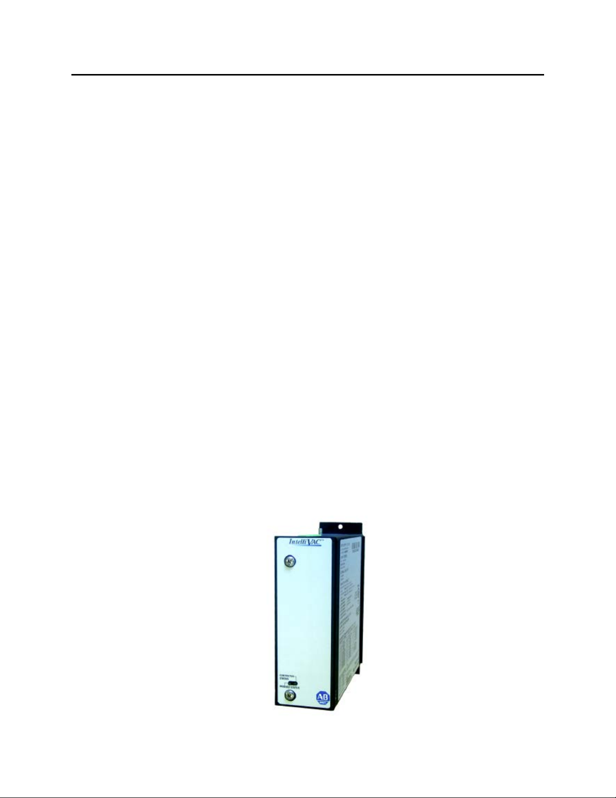
Description Intelli VAC i s an effici ent a nd flexible solut io n for cont rolli ng m edium
vo lta ge va cuum cont actors used i n motor st ar ter and f eeder
applications. IntelliVAC may be used to control both 400 and 800
Amp co nta ctors. E lectri cally held a nd mecha nica lly la tched cont actor
types can be controlled with IntelliVAC.
1503-U M053B-EN-P – Ju ne 2013
Page 6
1-2 Product Description
Description (cont.)
Figure 1.1 – IntelliVAC Contactor Control Module
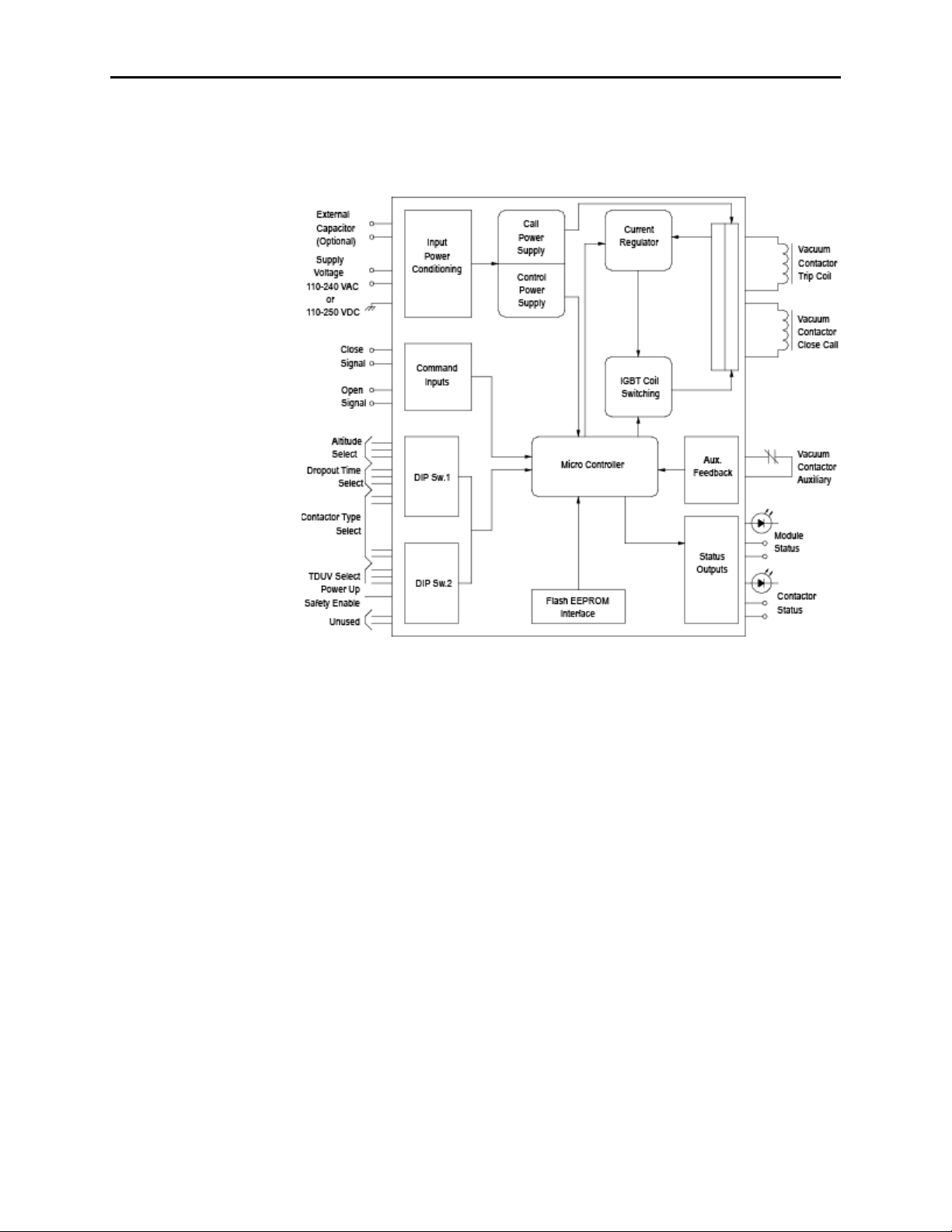
Figure 1.2 – IntelliVAC Block Diagram
IntelliVAC Features
A wi de ra nge of supp ly vo lta ge (11 0 – 240 V AC 50/60 Hz, 110 -
250 V DC) a llows i mplementation i n multiple ap plications
Co nsist ent vacuu m cont actor pi ck-up ti me (a t a g iven sup ply
voltage) ensures repea ta ble per for mance
Selectable vacu um co nta ctor dr op-out time improves coordination
with upst rea m po wer fuses
Elect roni c alt it ude compensati on (40 0 A only) elim ina tes
mechanical com pensa tion requi red for alti tud es abov e 1,0 00
met ers (800 A contactors include a user -fri endly alt itud e
adjustment)
Power loss ride-t hro ugh ( TDU V) a llows t he va cuum cont actor to
rem ai n closed du ring short po wer lo ss (ma y req uir e an o ptional
ext erna l capacit or, dependant on ri de-through ti me)
1503-U M053B- EN-P – Ju ne 2013
Page 7

Product D escri ption 1-3
IntelliVAC Features (cont.)
Anti-kiss a nd anti -pumpi ng protection ensure tha t t he vacuu m
contactor close – open sequence occurs as expected, avoiding rapid
re-closure due to fau lty cont rol d evices
Delayed r esta rt pr otects t he vacuu m conta ctor b y ensuri ng t hat the
rat ed dut y cycle is not exceeded
Tempo rary jog function (elect rically held cont act ors o nly) allows
the motor to be posi ti oned for p rocess set -up
IntelliVAC Versions
Series A
Series B
Series C
Up dat ed versi on o f the Series B modu le.
Ther e are t wo versi ons o f I ntelli VAC co ntr ol. The
fi rst type i s used to control v acuu m cont actors that are
electrically held, with a single electrical coil that is
economized electronically. The second is used to
control mecha nica lly lat ched va cuum contact ors.
There is a single version of IntelliVAC, to control
bo th elect ri cally held and mechanically latched
va cuum cont act ors.
Series D Minor functionality (firmware) enhancements
(primarily related to definition and handling of Faults
and Wa rning s).
Series E R evised ha rdware to allow co nnecti on t o t he
Int elliVAC Plus or I ntelli VAC MC> Remo val o f the
mi ni Din co nnecto r for fla shing fi rmwa re (firmwa re is
now flashed using the IntelliVAC Plus or IntelliVAC
MC boards) . N ew inpu t circui ts t o redu ce ther mal
ou tpu t, and d ecrease sensi ti vit y t o leakage cur rent .
Refer t o Cha pter 6, for cat alog num bers for each version of Int elliVAC.
Note: A Series C, D or E IntelliVAC m odule can be used t o rep lace
a Seri es A or Series B module. When rep laci ng an o lder ser ies
of Int elliVAC wi th a newer one, not e tha t t he Module and
Co nta ctor Status o utpu ts may functi on di fferent ly. R efer t o
publication 1503-UM051C-EN-P and/or Chapter 5 of this
1503-U M053B-EN-P – Ju ne 2013
Page 8

1-4 Product Description
do cument , a nd make any necessa ry changes to the co ntrol
circuit.
1503-U M053B- EN-P – Ju ne 2013
Page 9

Product D escri ption 1-5
Specifications Mounting and Connections
The IntelliVAC control mod ules a re m ount ed usi ng t wo ( 2) scr ews ( see
Figur e 1.3 ). They are typi cally locat ed in the lo w volt age control pa nel
of the medi um vo lta ge cont roller (Bullet in 1500 /190 0 cont rollers, in
the case of Rockwell Automation).
Intelli VAC i s int erfa ced to the Bulleti n 1502 vacuum cont act ors u sing
a “qui ck” co nnector , locat ed at the mod ule, a wir e ha rness and “qui ck”
connector at the co nta cto r. Control po wer a nd ot her co ntr ol ci rcui t
connect ions are simila rly a chieved wi th “qui ck” co nnecto rs.
Configuration
IntelliVAC is easily confi gur ed for a wi de va riety of m ediu m vo lta ge
mo to r and feeder cont rol app lica ti ons. It is configu red using D IP
swi tches, locat ed withi n the enclosur e (fr ont side) . Plea se refer to
Chapter 4 for information.
Bulletin 1500/1900 controllers are shipped with IntelliVAC preconfi gur ed for t he requ ired a ppli cat io n. Please refer to the docu ment s
provided wit h the ord er.
Firmware
IntelliVAC ha s fir mwa re stored i n flash EEP ROM; t heref ore, thi s ma y
be updated in the field (if necessary). The IntelliVAC
is up dat ed usi ng ei ther the I ntelliVAC Plus, or Int elliVAC MC
supplem enta ry boa rds.
The firmware versi on suppli ed wi th t he mod ule is di splay ed on top o f
the DIP swi tches ( see Fig ure 4 .1) .
Seri es C modules use only ver sion 2.00 3 app lica ti on fi rmwa re. This
fi rmwa re is also compa ti ble wi th t he Seri es A a nd B modu les. Series D
modules use only version 3.001 or 3.002 application firmware. This
fi rmwa re is not com pat ib le wit h any ot her S eri es Letter mod ules.
Seri es E modules use o n 4 .00 4 or newer fi rmwa re. This fi rmwa re is not
com pati ble wi th a ny ot her S eries Let ter modules.
Refer t o Cha pter 6 f or p art number s of t he va rious ser ies of modu les.
The Series Letter of the mo dule i s print ed on t he label on t he cover of
the module, besi de the pa rt num ber.
board firmware
1503-U M053B-EN-P – Ju ne 2013
Page 10

1-6 Product Description
Table 1 .A – El ectri cal Ratings
Main Inpu t Vo ltage
(L1 to L2/N)
AC – 110 to 240 V rms, +10/-15%, 4 7 to 63 Hz
DC – 1 10 to 250 V, +10/-15%
Main Input Current
(L1 to L2/N )
Command Inputs
⊇ ⊂
Des cription
Con tac tor Ratin gs
(A mps)
Control Voltage
(AC o r DC)
Inr ush Current 400/800 120/240
Idle Current
(Maximum without contactor coil
400/800 120/240 125 mA 35 mA
energized)
Hold Current ⊄ (maximum)
400/800 120/240 300 mA 100 mA
120 4.6 A 3.6 A
400
Close Current ⊄
(0.2 sec)
240 3.4 A 3.3 A
120 11.3 A 4.8 A
800
240 8.9 A 4.5 A
120 7.0 A 3.7 A
400
Trip Current (latch) ⊄
(0.2 sec)
240 3.6 A 2.0 A
120 7.0 A 3.3 A
800
240 4.3 A 1.9 A
AC – 70 to 240 V rms
DC – 70 to 250 V
Max imum on state current f or open or close command:
@ 276 V AC, 60Hz, TA = 60°C
11mA
AC
2.4mA
@ 276 V DC, TA = 60°C
DC
Minimum on state curr ent f or open or close command:
@ 70 V AC, 60Hz, TA = 60°C
2.5mA
1.2 m A @ 68 V DC, T
AC
= 60°C
A
Max imum off state current for open or close command:
= 60°C
A
= 60°C
A
1.9 µA @ 60 V AC, 60 Hz, T
900 µA @ 60 V DC, T
AC Rating DC Rating
25 A peak (1/2
cycle )
25 A peak
1503-U M053B- EN-P – Ju ne 2013
Status Outp ut Contacts
Standards and Approvals
⊇ T
Ambient Temperature
A =
⊄ Includes idle current.
⊂ Ensure compatibility of IntelliVAC input ratings with those of circuit components activating these inputs.
Consider means of isolating/loading these signals, as required (using interposing relays or load resist ors.)
Consult factory for assistance, if needed. The Series C and D IntelliVACs a re compatible with most PLC outputs,
and have been verified with Rockwell Automation OA t ype 120V triac outputs. See Chapter 3, Wiring Guidelines.
AC – 250 V rms, 5 A, R load; 2 A (reactive), PF = 0.4
DC – 30 V, 5 A, R load; 2 A (reactive), L/R = 7 ms
CE, cULus, CS A, IEC pending
Page 11
Product D escri ption 1-7
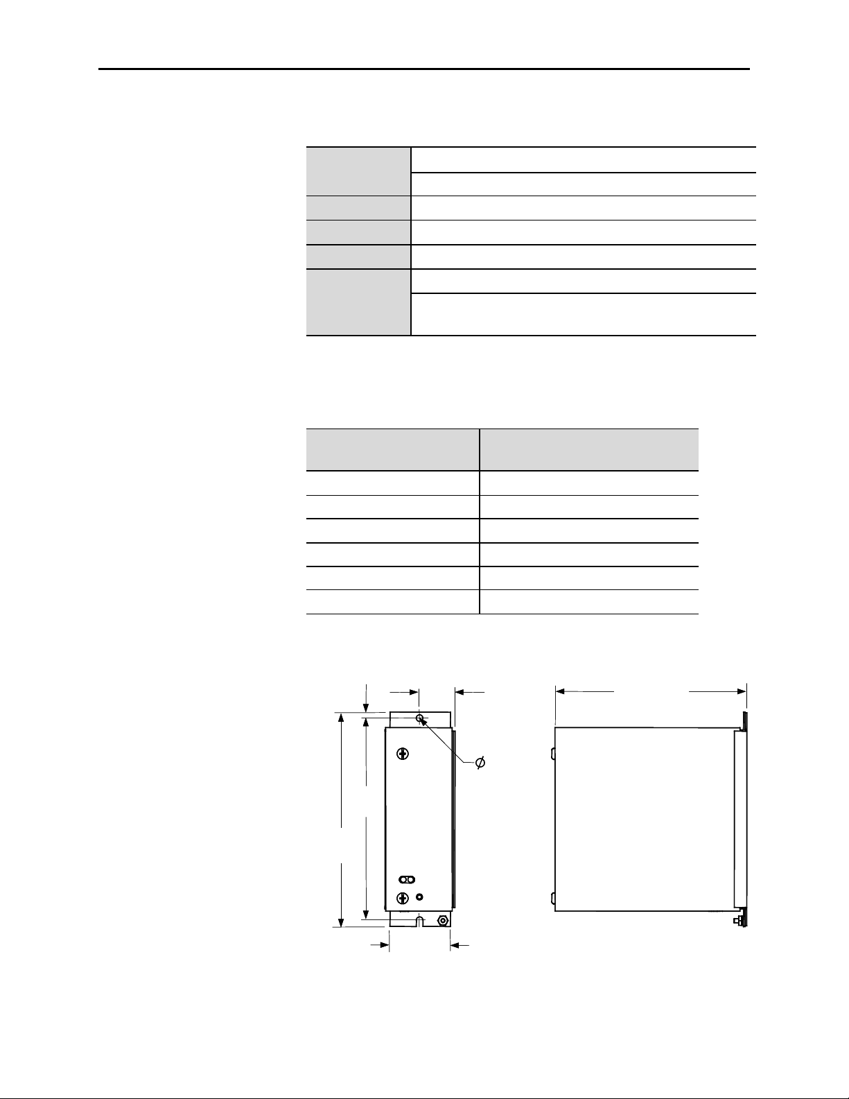
5.1 (0.20)
Dimensions in mm (inches)
29.7
(1.17)
174.8
(6.88)
185.3
(7.29)
59.4
(2.34)
165.9 (6.53)
5.8 (0.228)
2 places
5.1 (0.20)
Dimensions in mm (inches)
29.7
(1.17)
174.8
(6.88)
185.3
(7.29)
59.4
(2.34)
165.9 (6.53)
5.8 (0.228)
2 places
Specifications (cont.)
Table 1 .B – Mechani cal Ratings
Ope rat ing: 0° to 60°C ambient at the control module
Tempe rature
Non-Opera ting: -40° to 85°C
Altitud e
Po llution
Hu midity
Shock and Vibration
(Operational)
Ambient temperature is derated at altitudes above 1,000 meters (3,300 feet).
Please refer to Table 1.C.
-1000 to 5000 meters
Pollution lev el II (as def ined by UL 840 and IEC 60664-1)
95% non-condensi ng
Shock – 15 g peak, 11 milliseconds
Vibra tion – 10 to 57 Hz, 0.015 inch displacement peak t o peak
– 57 to 150 Hz, 2.5 g acceler ation
Table 1 .C – Altitude Derating
Altitude
-1000 to 0 60
1 to 1000 60
1001 to 2000 58
2001 to 3000 56
3001 to 4000 54
4001 to 5000 52
Maximum Operating Ambient
at the control module (°C)
Derate by 2°C / 1000 m for high altitude operation
Figure 1.3 – Mechanical Dimensions
1503-U M053B-EN-P – Ju ne 2013
Page 12

Chapter 2
Receiving and Storage
Receiving Up on receiving the cont roller, r emove t he pa cki ng and check fo r da ma ge
tha t ma y ha ve occurred during shi ppi ng. Report a ny da mage immedi ately
to the cla im s office of the ca rrier.
NOTE: If t he Int elliVAC m odule is a n integra l com ponent of a
com plete MV co ntr oller (Bullet in 150 0/19 00), special receivi ng a nd
ha ndling inst ruct io ns will app ly. For deta ils, refer to the ser vice ma nual
pr ovi ded with t he equipm ent.
Storage It is important to consider the following storage requi rem ents i f yo u ar e
not inst alli ng your cont roller i mm edia tely aft er r eceivi ng i t.
• St ore t he controller i n a clean, dry , dust -free environment.
• St ora ge t emper at ure sho uld b e maint ai ned bet ween -40°C and 85°C (40°F and 185°F).
• Relati ve hum idity must not exceed 9 5%, non-condensing.
1503-UM053B -EN-P – Ju ne 2013
Page 13

2-2 Receiving and Storage
(This page is intentionally left blank)
1503-U M053B -EN-P – Ju ne 2013
Page 14

Chapter 3
A T T E N T I O N
A T T E N T I O N
A T T E N T I O NA T T E N T I O N
A T T E N T I O NA T T E N T I O N
Safety and Codes
Installation and Wiring
General Precautions In add it ion t o the preca ut ions list ed throu ghout t his manual, t he
followi ng st at ement s, whi ch ar e g eneral t o the system, m ust be read a nd
understood.
The cont roller cont ains ESD (electrostat ic
discharge) sensit ive part s and a ssemblies. St ati c
control pr ecaut io ns ar e requi red when
inst alli ng test ing, ser vici ng, o r repa iri ng the
assembly . Co mpo nent da ma ge ma y result if
ES D cont rol pr ocedu res are not followed. I f
you are not familiar with static control
pr ocedures, refer t o app lica ble ES D prot ecti on
handbooks.
An incorrectly app lied o r inst alled controller
can dam age compo nents o r reduce pro duct life.
Wi ri ng or a pplicati on err ors, su ch as i ncorrect
or ina dequ ate AC su pply, or excessive am bient
temper at ures, ma y result in m alfu ncti on of t he
system.
Only personnel fam ili ar wit h the cont roller a nd
associ at ed machi nery sho uld plan or implem ent
the installation, start-up, a nd subseq uent
ma intena nce of t he syst em. Fa ilur e to do t his
ma y r esult i n persona l injury a nd/or equi pment
damage.
1503-U M053B-EN- P – Ju ne 2013
Page 15
3-2 Installation and Wir ing
A T T E N T I O N
A T T E N T I O N
The Canadi an E lectr ical Co de (CEC) ,
Na ti ona l Electrica l Code (N EC) , or other local
cod es out line pr ovi sio ns for safely i nsta lling
electrical equi pment. Inst alla tion MU ST
com ply wi th speci fica ti ons regardi ng wi re t ype,
conduct or si zes, bra nch ci rcui t pro tect io n,
int erlock ing and di sconnect devi ces. Fa ilure t o
do so may resu lt i n personal i njury and/or
equi pment da mage.
Arrangements
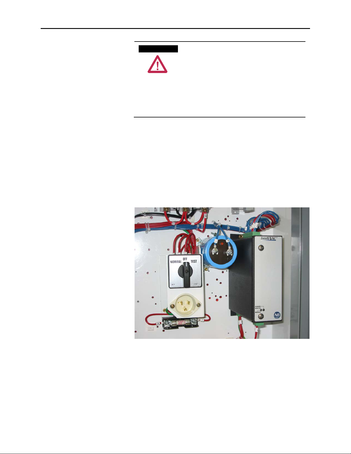
Integral to an Allen-Bradley M V Controller
The Int elliVAC i s ava ila ble a s a pri ma ry com ponent of a n Allen-Bradley
The Int elliVAC i s offer ed in two arrangement s, Integr al ( par t of a
Bulletin 1500/ 1900 MV cont ro ller) o r a s an OEM co mpo nent.
Bulletin 1500/1900 MV controller as shown in Figure 3.1.
Figure 3.1 – Typical IntelliVAC Install atio n within a Bul letin 15 00/19 00 MV Controller (Shown
with o ptional external cap acitor)
1503-U M053B -EN-P – Ju ne 2013
Page 16

Installati on a nd Wir ing 3-3
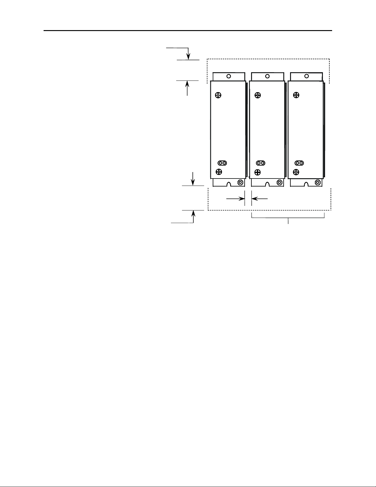
OEM
The Int elliVAC may be o rder ed as an OEM compo nent. This a llows the
OEM t o mou nt t he com ponents i n a confi gur at ion m ost sui tab le to the
mo to r controller equi pment lay out . Ca re m ust b e exerci sed t o ensur e t he
Intelli VAC ha s adequ ate venti lat ion pr ovided arou nd it. Refer to Figur e
3.2 fo r mount ing t he Int elliVAC. It i s recom mended that a mini mum o f
1. 5 inches ( 38. 1mm ) of free air spa ce be pr ovi ded b etween t he
Intelli VAC and any solid b arrier abov e or b elow.
The OEM i s responsible for controller fusing, mot or overload pro tection,
control devi ces (eg. Start/Stop push buttons), and wiring between the
Intelli VAC and 15 02 v acuu m contactor (using optio nal wir e harness) .
Wi ri ng and mou nti ng fo r opt ional i tem s, such a s TDU V Capacitor, are
also the OEM’s responsibilit y. R efer t o Figur e 3.3 for basic connect io ns.
1503-U M053B-EN- P – Ju ne 2013
Page 17
3-4 Installation and Wir ing
38.1
(1.50)
38.1
(1.50)
6.4 (0.25)
Additional Modules
(as required)
Minimum bottom clearance
Minimum top clearance
Dimensions in mm (inches)
38.1
(1.50)
38.1
(1.50)
6.4 (0.25)
Additional Modules
(as required)
Minimum bottom clearance
Minimum top clearance
Dimensions in mm (inches)
Arrangements (cont.)
Figure 3.2 – Typical Mounting Configurations
Note: Adja cent Int elliVAC modu les may be mo unted wit h a
minimum separation of 6.4 mm (0.25 inches).
1503-U M053B -EN-P – Ju ne 2013
Page 18

Installati on a nd Wir ing 3-5
MOV
32
1
EC
-
+
4
TCO
12
11
AUX CCO
5
6
L1 L2/NG
+ -
STOP
START
OVERLOAD
CONTROL
POWER
FUSE
*
7 8
OPEN
16
15
CONTACTOR
STATUS
M
M-INTELLIVAC
M
CAPACITOR
(OPTIONAL)
+ -
9 10
CLOSE
14
13
MODULE
STATUS
CONTROL POWER
INPUT POWER
CONFIGURATION
DIP SWITCHES
Figu re 3. 3 – IntelliVAC Typical Schematic (Electrically Held Vacuum Co ntactor)
1503-U M053B-EN- P – Ju ne 2013
Page 19

3-6 Installation and Wir ing
A T T E N T I O N
A T T E N T I O N
Fuse Protection The IntelliVAC module requires external fuse protection to coordinate
wi th t he power supply and conta ctor. The fuse rati ngs shown i n Table
3.A allow the passage of inrush currents expected when the contactor is
closed , or fro m reco mm ended externa l capa cit ors fo r the TD UV o ption.
They will also protect the contact or co ils i n the event of a m odule
malfunction.
The recommended fuses have been test ed to ensure reliable protection of
the module. If t he su pply vo lta ge is DC, the m odule must be used wit h an
ext erna l fuse t hat is a ppr oved fo r and r at ed to interrupt t he DC voltage
supply . The t ypes listed a re Fer raz-Shawmut Mid get Fuses ( 1-1/2" X
13/32"). The TRM is a time-delay type, rat ed 250 VAC. The ATM i s a
fast-a cti ng t ype, rated 5 00 VD C.
Table 3 .A – Intelli VAC Fuse Protection
Rated Supply Voltage Contactor Type
400A EH TRM 2 T RM 3.2
110/120 VAC
220/240 VAC
125 VDC
250 VDC
EH = Electrically Held vacuum contactor
ML = Mechanical Latch vacuum contactor
800A EH
400/800A ML
400A EH TRM 2 TRM 6.25
800A EH
400/800A ML
400A EH/ML
800A EH/ML ATM 5 ATM 6
400A EH/ML
800A EH/ML
Recommended Fuse
(min imum) (ma ximum)
TRM 2
TRM 2
TRM 2
TRM 2
ATM 3
ATM 3
ATM 5
TRM 6.25
TRM 3.2
TRM 6.25
TRM 6.25
ATM 3
ATM 5
ATM 6
Note: If ext erna l ca paci tors a re co nnected, o r more tha n one
Intelli VAC module i s pr ot ected b y a common cont rol fuse, the
ma xi mum recommended fuse should be used to pr event fuse
op ening due to incr eased inr ush curr ent when co ntr ol po wer i s
applied.
Grounding The Intelli VAC modu le must be connect ed to a common ground
termi nal (P E) on t he cont roller pa nel. The gr ound t erm ina l is locat ed on
the bottom of m odule enclo sure (refer t o Figur e 3.4 ).
It is important that IntelliVAC is properly
gr ounded usi ng the gro und co nnection
provided. Fai lure to do so may resu lt i n damage
to equ ipm ent o r per sona l injury.
1503-U M053B -EN-P – Ju ne 2013
Page 20

Installati on a nd Wir ing 3-7
1503-U M053B-EN- P – Ju ne 2013
Page 21

3-8 Installation and Wir ing
L2/NL1
CONTACTOR STATUS OUTPUT (N.O.)
MODULE S TATUS OUTPUT (N.O.)
POWER INPUT
13 14 15 16
Ground Connecti on
Connections There are three green connectors on the IntelliVAC module for
connect ions to the co ntr ol circui tr y. Connect or p lugs a re pr ovi ded wit h
the module. If a ddi ti ona l plugs a re req uir ed, r efer t o Chapt er 6, Spare
parts.
Control Power
Co ntrol po wer i s appli ed to the mo dule wi th a two -pole co nnecto r
The IntelliVAC can accept either AC or DC control po wer. Refer to
Table 1.A for a ccepta ble input power and co ntr ol si gnal rat ings.
located at the bottom rear portion of the module. Refer to Figure 3.4 for
connections. The ‘L1’ connection is i ntend ed to be t he ‘Hot’ o r ‘+ ’ side
of t he co ntr ol po wer, and the ‘L2 /N’ connect ion i s int ended to be the
‘Neutral’, ‘Return’, or ‘-’ si de of the co ntr ol po wer.
St atus Relays
Stat us rela y connect ions a re accessed wit h a fo ur-pole connect or lo cat ed
at the bottom front portion of the mo dule. Refer t o Figu re 3. 4 for
connect ions. There are two sta tus r elay s, each wit h one nor mally-open
contact:
Module Status: Terminals 13 and 14
Contactor Status: Terminals 15 and 16
Refer t o Cha pter 5 Monitoring and Troubleshooting for a descript io n of
op erati on fo r the rela ys.
Refer t o Table 1. A fo r elect rical ratings of t he sta tu s relays.
Figure 3.4 – Bottom side connections
1503-U M053B -EN-P – Ju ne 2013
Page 22

Installati on a nd Wir ing 3-9
1503-U M053B-EN- P – Ju ne 2013
Page 23

3-10 Installation and Wir ing
CONTACTOR INTERFACE
11 128 9 105 6 72 3 41
EX. CAP.
Interface Connections
All other control int erfa ce connect io ns a re made a t a twelve-pole
connect or loca ted on the to p of the modu le. Ref er to Figu re 3. 5 and
Table 3.B fo r connect ions ( and Table 1.A for electrical rat ings).
Refer t o the Wiring Guidelines section i n thi s chapt er fo r gui dance i n
ma ki ng connect io ns to the co ntrol ci rcui t.
Figu re 3. 5 – Top side co nnection s
Table 3 .B – Terminal Assignments for IntelliVAC Interface Connections
Terminal No. Termina l De s igna tio n Des cription
1 External capacitor (negati ve)
2 External capacitor (positive)
3 Lat ch tr ip coil (com mon)
4 Lat ch tr ip coil
5 Close coil (common)
6 Close coil
7 Open / Jog comm and
8 Open / Jog command (common)
9 Close command
10 Close command (common)
11 Contactor auxiliary contact
12 Cont actor auxiliary cont act
Refe r to T able 1.A for ele ctri cal rat ings .
No connection required if option is not used.
Ensure compatibilit y of IntelliVAC input ratings with those of circuit components activating these inputs. C onsider means of
isolati ng/loading these signals, as required (using interposing relays or load resistors). Consult factory for assistance, if needed. The
Series C and D IntelliVACs are compatibl e with most PLC outpu ts, and ha ve been verified with Rockwell Automation OA type 120V
triac outputs. See Wiring Guidelines.
For electrically held contactor, this command will energize the close coil output (CCO).
For mechanically held contact or, this command will energize the trip coil output (TCO).
Power connection for TDUV or capacitor trip options
only
Out put for mechanical lat ch contact or trip coil
Output to close coil of electrically held &
mechanical latch contactor s
Input to open a mecha nical lat ch contactor or jog
an electrically held contactor (mutually exclusive)
Input to initiate the closure of electrically held and
mechanical latch contactor s
Input to indicate the state of the contactor
(typically wired to a normally closed auxiliary
contact )
1503-U M053B -EN-P – Ju ne 2013
Page 24

Installati on a nd Wir ing 3-11
A T T E N T I O NA T T E N T I O N
Wiring Guidelines Electrically
The IntelliVAC can be applied wi th two- or three-wire control circui ts.
Held Contactors
The cont rol syst em utili zed will determ ine t he confi gur at ion of t he input
wiring. Consider the following input and output for the type of control
used:
• Term i nals 9 and 10 – Close Contactor
• Ter mi na ls 15 and 16 – Contactor Status
In eit her ca se, the CLOSE inpu t must recei ve a maint ai ned vo ltage hi gh
to keep t he cont act or closed.
Note:
1. When used with electrically held contactors, the IntelliVAC allows
close co mm ands ever y six seconds. This is to ensure the rated
contactor duty cycle is not exceeded.
2. If IntelliVAC powers up configured for an electrically held contactor,
and t he va cuum cont act or is det ected as being closed, the module wi ll
not respond t o a close command u ntil t he va cuum contactor auxiliary
contact inp ut i s in the correct (closed) sta te a nd m odule power is
rem oved a nd re-applied. (See Cha pter 5)
3. In g enera l, a Clo se command should only be app lied 4 seconds aft er
energi zing I ntelli VAC.
For E mergency St op appli cat ions requiring
rem oval of power, a cont act should be pla ced in
the “L1” co ntrol po wer r ung t o t he I ntelli VAC.
If t he TD UV fea tur e is used, the cont act or wi ll
not open unt il t he progr am med TD UV t ime
has expired.
1503-U M053B-EN- P – Ju ne 2013
Page 25

3-12 Installation and Wir ing
-+
3
2
12
11
AUX
MOV
M
TCO
5
6
-+1
EC
CCO
4
9 10
M
CLOSE
N
G
OVERLOAD
*
CONTROL
POWER
FUSE
CONTROLPOWER
M
M-IV
M-IV
L
CR
CR
SOLID STATE
OUTPUT
INPUT POWER
*
Refer to Table 3.A for recom m ended f use sizing.
Cont rol with Solid-State Devices
When cont rol devi ces t hat employ electr onic or su ppressed outpu t
circu it s are used in the r ung( s) t hat cont rol the i nput s to the I ntelli VAC,
alterna te a rra ngem ents m ay be r equi red. D evices emplo ying transi stor or
triac out put cir cuit s have fini te i mped ance and allow a leak age cur rent to
flo w i n the blocki ng o r of f sta te. Some P LC a nd I/O m odules with r elay
ou tpu ts ha ve R-C snubb er circui ts a cross t he co nta ct t o sup press voltage
transi ents genera ted d uri ng cont act openi ng. The im peda nce of these
snubber circuit s also a llows lea kage cu rrent t o flow when the cont act s ar e
op en. The I ntelli VAC i nput cir cuit s have b een designed such that t ypi cal
ou tpu t lea kage cu rrents sho uld no t creat e unint ended o pera ti on of t he
contact or. The v ast majorit y of cont rol d evices m ay be di rectly connect ed
to the I ntelli VAC wit hout any ina ppr opri ate oper ation occur ring.
Thi s si tuation ca n be pr event ed by consi dera ti on of t he cont ro l devi ces
when desi gni ng t he co ntr ol syst em. With co ntrol dev ices tha t ha ve
excessi ve leakage cur rent (i.e. PLC or si mi lar control devi ces) consider
usi ng rela y ou tpu ts wi th now supp ression across the cont act s. I f thi s
canno t be do ne, consi der the leak age cur rent of the d evice to see if i t i s
com pati ble wi th t he Int elliVAC i nputs (see Ta ble 1.A) . If t he co ntrol
device is not compa ti ble consi der usi ng an i nter posi ng relay connect ed as
shown in Figur e 3.6 .
1503-U M053B -EN-P – Ju ne 2013
Figure 3.6 – Co ntr ol w it h So lid -State Devi ces
Page 26

Installati on a nd Wir ing 3-13
A T T E N T I O N
A T T E N T I O N
A T T E N T I O NA T T E N T I O N
CONTROL
POWER
FUSE
CAPACITOR
(OPTIONAL)
M-IV
EC
TCO
AUX
CCO
L2/N
L1
G
MOV
M
OVERLOAD
RUN
M-IV
CLOSE
* Refer to Table 3.A for recommended f use sizing.
EMERGENCY STOP
(when required)
M
1
2
4
3
11
6
12 5
CONTROL POWER
Two-Wire Control
Wiring Guidelines Electrically
Held Contactors (cont.)
Som e two-wire cont rol schemes ma y be configur ed such that a close
If usi ng two-wire cont rol, the CLOS E contact or i nput i s maint ained high
usi ng a si ngle cont act . Mom enta ri ly op ening thi s inp ut wi ll cause t he
Intelli VAC t o op en the cont act or. Mai ntaini ng the co nta ct wi ll provide a
CLOS E command to Intelli VAC (g iven t hat all permissives are satisfi ed).
If a fa ult occur s, in add iti on to cycling cont rol p ower t o the Int elliVAC
module, the CLOSE command must be removed for a minimum of 4
seconds, before bei ng re-app lied. R efer t o Figur e 3.7 .
com ma nd is pr esent when Int elliVAC is energized. In this case, the
Power-Up S afet y fea ture may be d isabled b y sett ing DIP swi tch 1 2
accordingly. Refer t o Ta ble 4.B.
Only disable the Power-U p safet y fea ture when
abso lutely necessa ry. Doing so can create
unsa fe oper at ing condi ti ons.
For E mergency St op appli cat ions requi ring
rem oval of power, a cont act should be pla ced in
the “L1” co ntrol po wer r ung t o t he I ntelli VAC.
If t he TD UV fea tur e is used, the cont act or wi ll
not open unt il t he progr am med TD UV t ime
ha s exp ired.
1503-U M053B-EN- P – Ju ne 2013
Page 27

3-14 Installation and Wir ing
A T T E N T I O N
A T T E N T I O N
* Refer to Table 3.A for recommended f use sizing.
MOV
32
1
EC
-
+
4
TCO
12
11
AUX CCO
5
6
L1 L2/NG
+ -
STOP
START
OVERLOAD
CONTROL
POWER
FUSE
*
M-IV
9 10
CLOSE
M-IV
15 16
CONTACTOR
STATUS
M
M-IV
M
CAPACITOR
(OPTIONAL)
CONTROL POWER
EMERGENCY STOP
(when required)
Fig ure 3 .7 – Two-Wi re C ont rol
Three-Wire Control
If using three-wi re co ntrol, t he CLOSE co nta cto r inpu t i s maint ained
hi gh usi ng t wo co nta cts. Momenta rily o peni ng thi s inp ut will ca use the
Intelli VAC t o op en the cont act or. Mom enta rily closing the S TART
contact will provi de a CLOSE co mmand to Intelli VAC (gi ven t hat all
per missives are sati sfied).
In thi s confi gura tion, the S TATUS outp ut a cts as a seal-i n cont act. If a
fa ult occu rs, in a ddition t o cycling control power over t o the IntelliVAC
module, the CLOSE command must be removed for a minimum of 4
seconds b efore being re-app lied. Refer to Fi gur e 3.8 .
For E mergency St op appli cat ions requi ring
rem oval of power, a cont act should be pla ced in
the “L1” control power rung to the IntelliVAC.
If t he TD UV fea tur e is used, the cont act or wi ll
not open unt il t he progr am med TD UV t ime
has expired.
Fig ure 3 .8 – T hree-W ir e Con tro l
1503-U M053B -EN-P – Ju ne 2013
Page 28

Installati on a nd Wir ing 3-15
CLOSE COMMAND
TO MICRO
MICRO OUTPUT
TO CLOSE COIL
CONTACTOR STATUS
RELAY OU T P U T
CONTACTOR
AUXLIARY
INPUT TO MICRO
CLOSE LEVEL OF
CURRENT TO CLOSE
COIL
MODULE STATUS
RELAY OUTPUT
Contact status relay closes on request to close. It will open if the contactor aux i liary contact does not close within 200 millisec onds and
module will fault (opening module status relay).
15mS
200mS
90mS
(@120VAC)
80mS
60mS
5mS
SELECTABLE DROP
OUT TIME
(0 TO 190mS)
CLAMP DELAY
DEBOUNCE
NATURAL
CONTACTOR
DROP OUT
CONTACTOR PICK UP
ACKNOWLEDGE
WINDOW
DEBOUNCE
30mS
For this example, the 130 milli s econd drop-out time has been selected. The base drop-out time is 50 milliseconds . The microcontroller delay i s
130-50=80 milliseconds.
15mS
Wiring Guidelines Electrically
Held Contactors (cont.)
Figu re 3.9 – Ti ming Diag ram 4 00 A (Electrically H eld) Co ntactor
for IntelliVAC Control with three-wire Control
1503-U M053B-EN- P – Ju ne 2013
Page 29

3-16 Installation and Wir ing
MOV
32
1
EC
-
+
4
TCO
12
11
AUX CCO
5
6
L1 L2/NG
+ -
CLOSE
OVERLOAD
CONTROL
POWER
FUSE
*
CONTROL POWER
M-IV
9 10
CLOSE
CC
M-IV
M
MOV
TC
M
+ -
M-IV
7 8
OPEN
OPEN
OVERLOAD
* Refer to Table 3.A for recommended f use sizing.
Intelli VAC cont rol m ay be used fo r mecha nica l la tch co nta cto rs.
Wiring Guidelines Mechanical
Latch Contactors
A momenta ry co ntr ol signal i s needed to close the co nta ctor, a nd a second
mo ment ar y control si gna l is need ed t o o pen the cont act or. The
mo ment ar y op en/close commands m ust be at least 50 m illi seconds in
duration.
Refer t o Figu re 3. 10 for a typi cal m echanical la tch co ntr ol scheme.
Note:
1. A mecha nica l lat ch cont act or m ay already be closed when po wer i s
app lied t o t he Int elliVAC cont rol module.
2. It is permissible to apply an open command t o t he Int elliVAC
mo dule a s power is re-applied.
Figu re 3.10 – Mechan ical Latch Contactor Control
1503-U M053B -EN-P – Ju ne 2013
Page 30

Installati on a nd Wir ing 3-17
Mechanical Latch Contactors
Capacitor Trip
The Int elliVAC can be confi gured to pr ovi de capa cit or trip functionality
wi th m echanical la tch cont act ors. A cap acit or m ust be connect ed t o t he
Intelli VAC (termina ls #1 a nd #2) in o rder to pr ovi de t his ca pabi lity . The
capa cit or pr ovi des cont rol p ower fo r the I ntelli VAC a s well as sto red
energy t o trip t he conta ctor. Ma ximum recom mended ca pacitor size is
1650 µF for 120V control or 330 µF for 240V control. Use of larger
capa cit ors wi ll requi re a current lim it ing circui t t o prev ent o pening the
control fuse on energization.
The Int elliVAC must recei ve an ‘OP EN’ command wi thin a few seconds
of losing AC control power . Thi s ti me li mit depends on voltage and
capa cit or size as sho wn in the t ab le below. If t he elapsed time exceeds thi s
limit , the cont act or ca nnot be t ripp ed by Intelli VAC. In t his case, the
contact or ca n be t ri pped b y pr essing t he relea se but to n on the doo r in
front of the contactor.
A sepa ra te volt age sour ce is need ed to pro vide the ‘OPEN’ command. This
may be taken from the ext ernal capacitor as shown in Figure 3.11.
Table 3 .C – Mechani cal Lat ch Contactor – Capacitor T rip Times
Con tac tor
Rating
400 Amp
No minal Vo lta ge
(Vac)
120
240
Ac tual
V
(Vac )
input
120
110 2.7
100 1.7
240
200 4.7
Note: Minimum capacitor voltage ratings:
Ext. Capa c itor
(µF)
1650
330
Ma x. time
for trip
(sec)
3.5
7.5
• 120V applications – 200V DC (250V DC preferred)
• 240V appli cat io ns – 400V DC (450V DC preferred)
1503-U M053B-EN- P – Ju ne 2013
Page 31

3-18 Installation and Wir ing
MOV
32
1
EC
-
+
4
TCO
12
11
AUX CCO
5
6
L1 L2/NG
+ -
CLOSE
OVERLOAD
CONTROL
POWER
FUSE
*
CONTROL POWER
M-IV
9 10
CLOSE
CC
M-IV
M
MOV
TC
M
+ -
M-IV
7 8
OPEN
OPEN
CAPACITOR
OVERLOAD
*
Refer to Table 3.A for recommended fuse sizing.
Figure 3.11 – Mechan ical L atch Contactor with Capacitor Trip Optio n
1503-U M053B -EN-P – Ju ne 2013
Page 32

Installati on a nd Wir ing 3-19
A T T E N T I O N
A T T E N T I O N
MOV
32
1
EC
-
+
4
TCO
12
11
AUX CCO
5
6
L1 L2/NG
+ -
STOP
START
OVERLOAD
CONTROL
POWER
FUSE
*
CONTROL POWER
M-IV
9 10
CLOSE
M-IV
15 16
CONTACTOR
STATUS
M
M-IV
M
+ -
JOG
M-IV
7 8
OPEN
* Refer to Table 3.A for recommended f use sizing.
EMERGENCY STOP
(when required)
Motor Jogging Control Note: J og funct io nali ty ca n wor k wi th elect ri cally held conta ctor only.
When used with electrically held contactors, the IntelliVAC allows close
com ma nds ever y six seconds. Thi s i s t o ensur e t he r at ed contact or dut y
cycle o f 60 0 op erations per hour is no t exceed ed.
For motor jogg ing oper ations, the seco nd control i nput, or OPEN
command, will clo se the co nta ctor fo r as long as t he i nput is p resent, and
op en t he cont act or when the i nput is r emoved. (Refer to Figure 3.12.)
Thi s m etho d will bypa ss t he sta nda rd six second mo tor r e-sta rt dela y fo r
jogg ing purpo ses only. Operati ons wi ll be limit ed to two sta rt s every
twelve seconds.
If t he TD UV fea tur e is used, the cont act or wi ll
not open unt il t he progr am med TD UV t ime
ha s exp ired. Ther efor e, appli cati ons requ iring
an i mmedi at e remov al of p ower during
emer gency stop co ndit ions are not comp at ible
wi th t he TDUV fea tu re.
Figu re 3. 12 – Motor Joggin g Con tro l
1503-U M053B-EN- P – Ju ne 2013
Page 33

3-20 Installation and Wir ing
A T T E N T I O NA T T E N T I O N
Undervoltage Protection The Int elliVAC cont roller prot ects t he conta ctor f rom cont rol vo lta ge
di ps and loss of p ower. It pro vides u nderv oltage release and pr events
att empt s to close the cont act or when t here is not suffici ent power
ava ila ble t o gu arant ee reliable closing of t he co nta cts. The underv oltage
pr otecti on wi ll be i nit ia ted u nder t he followi ng condit ions, r egardless o f
nominal control voltage:
1. I f the sup ply voltage dr ops b elow 90 V (AC or DC) duri ng the first
20 0 milli seconds after a Clo se co mma nd i s received . Thi s a ppli es to
bo th elect ri cally held and mecha nica l la tch co nta cto rs.
2. If t he supply volt age d rop s below 72 V (AC or DC) aft er t he 200
millisecond close sequence (electrically held contactors only).
Time Delay Undervoltage
The Int elliVAC can be confi gur ed to pr ovide time dela y under voltag e
(TDUV) pr ot ection. The f eatur e is a vailable to keep elect ri cally held
contact ors clo sed du ring a vo lta ge di p or brief power loss. Thi s opt ion
ma y r equi re the a ddi ti on of a capacit or (see below) . R efer to Chapt er 6
for typi cal ca pacit or si zing . The ca paci tor i s connected t o t ermina ls 1(-)
and 2(+) of the IntelliVAC. (Ref er to Figur e 3.1 3.)
If t he TD UV fea tur e is used, the cont act or wi ll
not open unt il t he progr am med TD UV t ime
ha s exp ired. Ther efor e, appli cati ons requ iring
an i mmedi at e remov al of p ower during
emer gency stop co ndit ions are not comp at ible
wi th t he TDUV fea tu re.
Table 4.B of t he “Set up a nd Co mm issioni ng” cha pt er ha s the dip swi tch
setti ngs to pr ovi de TD UV fr om 0. 2 to 2 seco nds. Int elliVAC can
pr ovi de TDUV prot ecti on wit hout t he use o f an ex terna l ca paci to r, a s
shown in Table 3.D.
Table 3 .D – Maximum TDUV Time (without Capacitor)
Control Volta ge
110/120 V
220/240 V
Max. TDUV Time (secs)
400 A 800 A
0.2
1.0
0.2
1.0
If t he underv olta ge cond it ion persi sts b eyond t he set dela y t ime, the
contact or will be op ened and an undervoltage fault or warning condition will
occu r (see Cha pter 5) .
1503-U M053B -EN-P – Ju ne 2013
Page 34

Installati on a nd Wir ing 3-21
1503-U M053B-EN- P – Ju ne 2013
Page 35

3-22 Installation and Wir ing
*
Refer to Table 3.A for recommended fuse sizing.
MOV
32
1
EC
-
+
4
TCO
12
11
AUX CCO
5
6
L1 L2/NG
+ -
STOP
START
OVERLOAD
CONTROL
POWER
FUSE
*
CONTROL POWER
M-IV
9 10
CLOSE
M-IV
15 16
CONTACTOR
STATUS
M
M-IV
M
CAPACITOR
(cont.)
Time Delay Undervoltage
Figure 3.13 – TDUV Control Circuit
1503-U M053B -EN-P – Ju ne 2013
Page 36

Chapter 4
S H O C K H A Z A R DS H O C K H A Z A R D
I M P O R T A N TI M P O R T A N T
Rem ove p ower fr om the modu le before
Ground Stud
Supply Power Input
Status Relay Outputs
LEDs
DIP Switches
Interface C onnections
Setup and Commissioning
IntelliVAC Configuration The I ntelli VAC modu le is confi gur ed for a speci fic a ppli cat ion by set ti ng
DIP switches. They are accessed by loosening the t wo scr ews on the front
of t he uni t, and rem oving the co ver b y slidi ng i t fo rwa rd. The swi tches
are f ound on t he fro nt ed ge of t he Int elliVAC circui t b oard ( see Figur e
4.1) . Ther e a re 16 swi tches, wit h num ber 1 being at the top closest to the
circu it boa rd pa rt numb er label. (Refer t o Table 4. B).
Hazardo us vo ltage is pr esent inside the module
whi ch may ca use per sona l i njury or death.
Rem ove a ll sou rces of po wer from the mo dule
and d ischa rge any connect ed cap aci tors before
rem oving the co ver.
rem oving the co ver a nd before cha nging t he
DIP switch set ti ngs. The new D IP swi tch
setti ngs are reco gni zed o nly on power-up.
Figure 4.1 – DIP Switch and Connector Locations
1503-U M053B-EN- P – Ju ne 2013
Page 37

4-2 Setup and Commissioning
Table 4 .A – DIP Switch Factory Default Settings
Altitude: 0 – 1000m
Ext. cap TDUV time: 0.2 sec
Power -Up Saf ety : Enable
An Intelli VAC unit shipped separ at ely fr om t he fa ctory wi ll hav e a
default configur at ion per Tab le 4.A.
Des cription
Drop-out tim e: 130 msec
Contactor config.: 400A EH
TDUV config.: No TDUV
DIP switch SW1
1 2 3 4 5 6 7 8 1 2 3 4 5 6 7 8
0 0 1
0 1 1
0 0 0 1
DIP switch SW2
0
0 0
0
IntelliVAC u nit s shipped i n a complete MV cont roller (Bulletin
15 00/ 1900 ) wi ll be confi gured to sui t t he insta lled ap plicati on (i.e.
contact or t ype). The user sho uld veri fy t he sett ings before energi zing the
equi pment . Tab le 4.B d efines t he sett ings fo r each swit ch.
Table 4 .B – IntelliVAC DIP Switch Explanation
1503-U M053B -EN-P – Ju ne 2013
Page 38

Setup and Commissio ning 4-3
The altit ude compensation by DIP switch settings applies to Series E 400 amp vacuum contactors onl y. Al l 800 amp cont act ors are ada pted
for altitude by altering the return springs. 800 amp contactors are to be set for 1 t o 1000m (001 DIP setting).
By-pass contactors in MV SMC applications must be set for 50 millisecond drop-out ti me.
Refer to Appendix A for typical drop-out time settings used when power fuses are provided by Rockwell Automation.
1503-U M053A-EN- P – Sep temb er 2008
Page 39

Monitoring and Troubleshooting
Introduction
The I ntelli VAC modu le has two lig ht em it ti ng di odes ( LED s) a nd rela y
ou tpu ts t o indi cat e the stat us of the co nta ctor and the m odule. The LED s
are v isi ble on t he fro nt o f the module and the rela y ou tpu ts a re accessed
on the bottom front of the module.
Chapter 5
Figure 5.1 – Int elli VAC LEDs
Note: Thi s u ser manua l cont ai ns info rma tio n for both Series C a nd
Seri es D Int elliVAC versions. Refer t o the correct info rma tion
belo w f or t he Intelli VAC series in use.
Module Status The Modu le St atus i s indi cat ed wi th a Green L ED if t he m odu le is
funct ioni ng pr oper ly and ha s a va lid confi gur at ion. If t he mo dule powers
up with an invalid configur at ion t he LED will be Red (fla shing once),
indicating a Fault condition which will not allow t he cont act or t o clo se. If
the m odule po wers up p rop erly and ex peri ences an undervolt age condition
when at tempt ing to close the co nta ctor or while t he co nta ctor is closed:
• Series C – the LED will be Red (Fa ult). If t he cont act or does not
close p rop erly, a Fault is generat ed, t he L ED t urns Red, and input s
are i nhi bited unt il t he mo dule power is remov ed and r eapp lied.
• Series D/E – the LED will be yellow (flashing once). If the
und ervo lta ge condi ti on i s corr ected during t he selected TDUV
int erva l (a s set via DIP swi tch) , then no rmal oper at ion resum es.
1503-U M053B-EN- P – Ju ne 2013
Page 40

5-2 Monit oring a nd Troubleshoot ing
I M P O R T A N T
I M P O R T A N T
Module Status (cont.) I f the pro cessor has an int erna l fau lt, the L ED will be Red, the o utp uts
will be cleared, and the processor must be reset ( input power must be
cycled). If the reset is successful, t he LED will be Green and t he modu le
wi ll respo nd to t he cont rol i nput s. The i nput comma nd m ust b e to ggled
before the module wi ll r espond to a new com mand (r isi ng edg e tr igg ered).
For S eri es D /E, t he Module St at us LE D is also used t o indi cat e various
“Warni ng” condit ions relat ed to the co nta cto r per formance (see Table
5.B).
Mod ule Stat us outpu t rela y has a norma lly o pen conta ct. The cont act is
op en dur ing a Fault condi ti on ( LED red) , and clo sed during a hea lthy
condi tion (LED green). The rela y i s open for some wa rning conditi ons,
but closed for less severe issues.
The module stat es ar e summ ar ized i n Tables 5.A a nd 5. B.
Contactor Status
Co nta ctor Status o utpu t relay has a normally op en cont act . The co nta ct
The cont act or st at es ar e summ ari zed in Tables 5.A a nd 5.B.
The Contactor Status is indicated with a yellow LED that is off until a
CLOSE command is r eceived. The yellow L ED will sta y on if t he
contact or clo ses proper ly, unt il t he cont act or i s opened . If the pro cessor
ha s a n int erna l fau lt, the LED wi ll b e red.
is open when the cont act or is op en ( LED off), and closed when the
contact or has received a close com ma nd (for 20 0 milli seconds) or if i t i s
closed (LE D on).
The LED s ar e red/ green t ypes wit h bo th
sections ON to pr oduce yellow. If viewed from
a sha rp a ngle, you may see only green or r ed.
Please view fro m di rect ly in fr ont of t he mo dule
to ensur e a ccura te co lor reco gnit ion.
1503-U M053B -EN-P – Ju ne 2013
Page 41

Monitorin g and Troubles hooti ng 5-3
Table 5 .A – IntelliVAC Status Indication (Series C only)
Con dition s
Des cription
Norm al Healthy Module and Contactor OPEN Green Closed Off Open
Norm al Healthy Module and Contactor CLOSED Green Closed Yellow Closed
War ning Invalid Comm and Present Yellow Closed Off Open
War ning Mechanical Latch Fail to Trip Yellow Open Yellow Closed
Fa ult Power Up with Contactor CLOSED Red – F lash 2 O pen Yellow Closed
Fa ult Contactor Fails to Pick Up Green Open Re d – Flash 1 O pen
Fa ult Contactor Drop Out During Hold Green Open Re d – Flash 2 O pen
Fa ult Long Contactor Drop Out Time Green O pen Red – Flash 3 Open
Fa ult Microcontroller M alf unction Red Open Re d Open
Fa ult Power Up with Invalid Dip Switch Configuration
Red – Flash 1 ⊂
Fa ult Undervoltage with a CLOSE Command Pr esent Red Open Off Ope n
Warning = Recoverable Condit ion – Remove and retry offending signal
Fa ult = No n-recoverable condition – Module power must be removed and re-applied.
Flash 1 = 1 Flash Red LED followed by a pause.
Fl as h 2 = 2 Consecutive Red LED flashes followed by a pause.
Flash 3 = 3 Consecutive Red LED flashes followed by a pause.
Only for Electrically Held Contactor
Invalid Command Types:
1. Close, Jog or Trip commands present during power up sequence.
2. Close or Jog command re-applied t oo quickly (be fore contactor opening sequence is verified).
Allow at least 60 msec, plus drop out delay time, before re-a pplying these signals.
NOTE : Contactor will only respond to a close command re-applications after th e re-start delay timer has expired.
3. Close and T rip commands present simultaneously (valid with Mechanical Latch contactors only).
U ndervoltage conditions are defined on page 3-17.
Modu le Statu s Contactor Status
LED Color Re lay LED Color Relay
Open Off Ope n
1503-U M053B-EN- P – Ju ne 2013
Page 42

5-4 Monit oring a nd Troubleshoot ing
11
11
12
12
Contactor Status (cont.)
Table 5 .B – IntelliVAC Status Indication (Series D only)
Con dition s
Norm al Healthy Module and Contactor OPE N Green Closed Off Open
Norm al Healthy Module and Contactor CLOSED Green Closed Yellow Closed
War ning Inv alid Command Present Yellow Closed Off Open
War ning Mechanical Latch Fail to Trip Yellow Closed Yellow Closed
Fa ult Power Up with Contactor CLOSED Re d – F lash 2 O pen Yellow Closed
War ning Contactor Fails to Pick Up Yellow – R1 Closed Off / Yellow Ope n/Close d
War ning Contactor Drop Out During Hold Yellow – R2 Closed Off / Yellow Open/ Closed
War ning Long Contactor Drop Out Time Yellow – R3 Closed Off / Yellow Ope n/Close d
Fa ult M icrocontroller Malfunction Red Ope n Red Open
Fa ult Power Up with Invalid Dip Switch Configuration
War ning Underv oltage wit h a CLO SE Command Pr esent Yellow – Fla shing Open/Closed Off / Yellow Open/Clos ed
Warnings will be cleared when a change of input state occurs, and the condition has been resolved.
Faults require control power to be removed until the unit resets
Flash 1 = 1 Flash Red LED followed by a pause
Flash 2 = 2 Consecutive Red LED flashes followed by a pause
Ye llow – R1 = Yellow with 1 Red flash followed by a pause
Ye llow – R2 = Yellow with 2 consecutive Red flashes followed by a pause
Ye llow – R3 = Yellow with 3 consecutive Red flashes followed by a pause
Invalid Command Types:
1. Close, Jog or Trip commands pre sent du ring p ower up seq ue nce
2. Close or Jog command re-applied to o quickly (be fore contactor o pening sequence is verified).
Allow at least 60 msec, plus drop out delay time, before re-a pplying these signals.
NOTE : Contactor will only respond to a close command re-a pplications after the re-start delay timer has expired.
3. Close and T rip commands present simultaneously (valid with Mechanical Latch contactors only).
Open during undervoltage, Closed if voltage restored
W ill reflect actual status of the contactor
Only for Electrically Held Contactor
Undervoltage condit ions are defined on page 3-17.
Des cription
Red – Flash 1 ⊂
Modu le Statu s Contactor Status
LED Color Re lay LED Color R ela y
Open Off Open
1503-U M053B -EN-P – Ju ne 2013
Page 43

Monitorin g and Troubles hooti ng 5-5
11
11
Table 5 .C - IntelliVAC Status Indication (S er i e s E on l y )
Con dition s
Des cription
Norm al Healthy Module and Contactor OPEN Green Closed Off O pen
Norm al Healthy Module and Contactor CLOSED Green Closed Yellow Closed
War ning Invalid Comm and Present Yellow Closed Of f Open
War ning Mechanical Latch Fail to Trip Yellow Closed Yellow Closed
Fa ult Power Up with Contactor CLOSED Red – Flash 2 Open Yellow Closed
War ning Contactor Fails to Pick Up Yellow – R1 Closed Off / Yellow Open/Clos ed
War ning Contactor Drop Out During Hold Yellow – R2 Closed Off / Yellow Open/Closed
War ning Long Contactor Drop Out Time Yellow – R3 Closed Of f / Yellow O pen/Clos ed
Fa ult Microcontroller M alf unction Red Open Red Open
Fa ult Power Up with Invalid Dip Switch Configuration
Fa ult Contactor Fails to Drop Out
Red – Flash 1 ⊂
Red – Flash 3
War ning Under volt age with a CLOSE Com mand Present Yellow – Fla shing O pen/Closed Of f / Yellow O pen/Clos ed
W arnings will be cleared when a change of input state occurs, and the condition has been resolve d.
Faults require control power to be removed until the unit resets
Flash 1 = 1 Flash Red LED followed by a pause
Flash 2 = 2 Consecutive Red LED flashes followed by a pause
Flash 3 = 3 Consecutive Red LED flashes followed by a pause
Ye llow – R1 = Y el low wit h 1 Red flash followed by a pause
Ye llow – R2 = Yellow with 2 consecutive Red flashes followed by a pause
Yellow – R3 = Yellow with 3 consecutive Red flashes followed by a pause
Invalid Command Types:
1. Close, Jog or Trip commands present during power up sequence
2. Close or Jog command re-applied to o quickly (be fore contactor o pening sequence is verified).
Allow at least 60 msec, plus drop out delay time, before re-a pplying these signals.
NOTE : Contactor will only respond to a close command re-applications after the re-start delay timer has expired.
3. Close and T rip commands present simultaneously (valid with Mechanical Latch contactors only).
Open during undervoltage, Closed if voltage restored
Will reflect actual status of th e co ntac tor
Modu le Statu s Contactor Status
LED Color Re lay LED Color Re lay
Open Off O pen
Open Re d Open
1503-U M053B-EN- P – Ju ne 2013
Page 44

5-6 Monit oring a nd Troubleshoot ing
1503-U M053B -EN-P – Ju ne 2013
Page 45

Monitorin g and Troubles hooti ng 5-7
Module status LED ‘Green’ and Contactor Status LED
Contactor Status (cont.)
Table 5 .D – Module Tr oubleshoo ting
Problem or Trip Indicated Indication of the following conditions Possible Solutions
Contactor does not energize • Motor Protection activated
Contactor closes momentar ily and will not
reclose.
Contactor fails to close. •
Refer t o Table 5. A (Series C) or Ta ble 5. B ( Series D) for definition of Module
• Investigate and reset
• Both Status LEDs ‘Off’
• Module Status LED ‘ Red’ upon power up • IntelliVAC faulted. Cycle control power to reset.
• Module Status ‘Red Flash 1’ upon power up • Impr oper setting of dip switches. Check settings and
• Loose connection in control circuit. • Verify contactor auxiliary set up. Reference Publication
• Module status LED ‘Red’ (Series C) and Contactor
Status LED ‘Off’
or
• Module status LED ‘Yellow – Flashing’ and Contact or
Status LED ‘Off’ (Series D)
‘Red Flash 1’ (Series C)
or
• Module status LED ‘Yellow-R1’ (Series D) and
Contactor Status LED ‘Off’
• Both status LEDs ‘Off ’ • Check internal control fuse. Verify IntelliVAC oper ation
• Check Control Power
• Loose connections in control circuit
• V erify IntelliVAC power input plug is in pla ce and
properly seated
• Verify internal control fuse has not opened (Refer to
Figure 4.1 for locat ion)
Replace IntelliVAC if unsuccessful.
cycle contr ol power.
1502-UM052_ -EN-P (400A) or 1502-UM051_ -EN-P
(800A ) – Auxiliary Contact Set-up Procedur e.
• Verify circuit continuity (is contactor plug connected
proper ly?)
• Under voltage f ault (no T DUV), contr ol volta ge dipped
below tr ip point. Verif y voltage lev els are 110 to 240
VAC, 110 to 250VDC
• Coil damaged or connect ions ar e loose. Repair and
cycle control power (Series C).
• Auxiliary Contact Assembly improperly adjusted.
Reference Publication 1502-UM052_ -EN-P (400A) or
1502-UM051_ -EN-P (800A) – Auxiliary Contact Set-up
Procedure. Cycle cont rol power to reset (Series C).
• A rmature Plate obstructed from closing to coil face.
Verify no foreign material behind the armature plate.
Cycle contr ol power to reset.
in test m ode before applying M edium V oltage. (Refer to
Fig. 4.1 for location.)
LE D sta tes.
1503-U M053B-EN- P – Ju ne 2013
Page 46

5-8 Monit oring a nd Troubleshoot ing
Module Status LED ‘Green’ and Contactor Status LED
R2’ and Contactor Status
Module Status LED ‘Yellow’ and Contactor Status LED
Table 5 .E – Minimum IntelliVAC Operational Supply Voltages
Table 5 .D – Module Tr oubleshoo ting (cont. )
Problem or Trip Indicated Indication of the following conditions Possible Solutions
Contactor opens during operation • Motor Protection activated • Investigate and reset.
• Stop command initiated • Verify circuit
• Module Status LE D ‘Red’ (Series C)
or ‘Yellow – Flashing’ (Series D)
•
‘Red Flash 2’ (Series C)
or
• Module Status LED ‘Yellow –
LED ‘Off’
• Both status LEDs ‘Off ’ • Check control v oltage and inter nal cont rol fuse. ( Refer
Contactor does not open (mechanical latch) •
‘Yellow’
• Under voltage f ault (no T DUV), contr ol volta ge dipped
below trip point. Verify voltage levels ar e 110 to 240
VAC, 110 to 250 VDC.
• With external capacitor and TDUV feature activated,
undervoltage condition for longer than program med
TDUV time. Undervoltage fault activated.
• Contactor Status feedback between Terminals 11 and
12 on the IntelliV AC has closed. The IntelliVAC will deenergize the coil, thinking t he contact or has opened
for other reasons.
to Figure 4.1 for location.)
• T rip me chanism is dam aged. Inspect and replace if
needed.
• Check for loose connections in the control circuit .
Contactor does not open
(electrically held)
• Series C – M odule Status LED ‘Green’ and Contactor
Status ‘Red Flash 3’
• Series D – M odule Status LED ‘Yellow – R3’ a nd
Contactor Status LED ‘Yellow’
• Contactor welded or mecha nisms binding. Inspect and
repair if needed.
Refer t o Table 5.A (Series C) or Table 5. B ( Series D) for definition of Module
LE D sta tes.
Voltage Level
Pick -Up 400/800 95
Drop-O ut 400/800 75
Tr ip (M echanical Latch)
Contactor Rating
(A mps)
400 70
800 80
Minimum Voltage
(VAC, 47 to 63 Hz)
1503-U M053B -EN-P – Ju ne 2013
Page 47

Monitorin g and Troubles hooti ng 5-9
1503-U M053B-EN- P – Ju ne 2013
Page 48

Chapter 6
Spare Parts
Spare Parts List IntelliVAC (electrically held) Series A 1503VC-BMC1
Intelli VAC (mecha nica l lat ch) S eries A 1503VC-BMC2
IntelliVAC (electrically held and
mecha nica l lat ch) S eries B 1503VC-BMC3
IntelliVAC (electrically held and
mechanical la tch) Series C and D
IntelliVAC (electrically held and 1503VC-BMC5
mecha nica l lat ch) S eries E
Internal Fuse: 6.3 A, 250 V (Littlefuse 21506.3) 80174-902-14-R
1503VC-BMC4
Multi-pole connect ors:
2 pole (module po wer) 80174-014-01-R
4 pole (status outputs) 80174-014-03-R
1 2 po le (coil a nd I/ O connect ions) 80174-014-11-R
Optional Equipment
TDUV Capacitor
For 110/120V AC control (1650 µF) 80158-779-51-R
For 220/240V AC control (330 µF) 80158-779-52-R
The Series Letter is printed on the large label on the right-hand side of the enclosure, beside the part
Includes m ounting bracket and ter minal guar ds
numbe r.
1503-U M053B-EN- P – Ju ne 2013
Page 49

6-2 Spar e Parts
(This page is intentionally left blank)
1503-U M053B -EN-P – Ju ne 2013
Page 50

Appendix A
Table A .1 – Typical Contactor Dr op-Out Ti me Settings
4R 6R 9R
18R
19R
2 x 24R ⊇ 100
2 x 32R
⊇
240 *
2 x 38R
⊇
2 x 48X
⊇
⊇
Typical Contactor Drop-out Time Settings
The cont act or d rop -out time settings shown i n the fo llowi ng t able are
typical minimum v alues u sed when the po wer fuses a re pr ovided a s par t of
a com plet e MV cont roller fr om R ockwell Automati on. The
recommenda ti ons are based o n Ferraz-Sha wmut po wer fuses. Ot her f use
types ma y req uir e alt erna te dr op-out ti me sett ings.
The Int elliVAC module D IP swi tches ar e set up to pr ovi de the m ini mum
drop-out ti mes shown (refer to Chapt er 4).
Fus e Ra ting Contactor Drop-out Time Setting (ms ec )
Vo ltag e De sign ation 400A 800A
2R
3R
50
12R
< 5000
⊇ Fus e not suitable for use with contactor.
24R
32R
38R ⊇
48X
57X ⊇ 200
2 x 57X
100
240
⊇
⊇
⊇
⊇
50
75
Note: The drop-o ut t im e is cho sen t o be equa l t o or gr eat er tha n
the int ersect ion of t he ra ted cont actor int erru pting cu rrent and
the fuse melt time curve (except where no ted * ).
1503-U M053B-EN-P – Ju ne 2013
Page 51

A-2 Typical Contactor Drop-out Times
Table A .1 – Typical Contactor Drop-o ut T im e Settings (c ont .)
50E
65E
150E
175E
75
450E
130
75
2 x 250E ⊇ 50
2 x 350E
75
2 x 400E
100
⊇
⊇
⊇
Fus e Ra ting Contactor Drop-out Time Settin g (mse c)
Vo ltag e Des igna tion 400A 800A
20E
30E
40E
80E
50
100
< 5000
100E
125E
200E
250E
300E
350E
400E
50
500E
600E
750E
900E
2 x 300E
2 x 450E
2 x 500E
2 x 600E
2 x 750E
2 x 900E ⊇ ⊇
⊇ Fuse not suitable for use with contactor.
240
240 *
⊇
⊇
⊇
⊇
⊇
⊇
⊇
200
240 *
75
130
240
240 *
Note: The drop-o ut t im e is cho sen t o be equ al to or g reat er tha n the
int ersection of t he ra ted cont act or i nterr upti ng cur rent and t he
fuse melt time curve (except where noted * ).
1503-UM 053B- EN-P – Ju ne 2013
Page 52

Typical Contactor Drop-o ut Times A-3
Table A .1 – Typical Contactor Drop-o ut T im e Settings (c ont .)
4R
6R
9R
75
32R
240 *
⊇ 75
48X
150
⊇
⊇
⊇
⊇
10E
15E
65E
150E
175E
Fus e Ra ting Contactor Drop-out Time Se tting (ms ec )
Vo ltag e Des igna tion 400A 800A
2R
3R
50
50
12R
18R
24R
150
7200
8250
⊇ Fuse not suit able for use with cont actor.
38R
57X
2 x 18R
2 x 24R
2 x 32R
2 x 38R
2 x 48X
2 x 57X
20E
25E
30E
40E
50E
80E
100E
125E
200E
⊇
200
⊇
⊇
⊇
⊇
⊇ ⊇
50 50
240 *
50
130
Note: The drop-out ti me i s chosen to be equ al t o or greater tha n the
intersection of the rat ed cont act or i nterrup ting cur rent and the
fuse melt time curve (except where noted *)
1503-U M053B-EN-P – Ju ne 2013
Page 53

A-4 Typical Contactor Drop-out Times
1503-UM 053B- EN-P – Ju ne 2013
Page 54

Page 55

Me dium Volt age Products,
Pu blication 1503-UM053B-EN-P – June 2013 Copy righ t © 2013 Rockw ell Aut oma ti on, I nc . A ll ri gh ts re s erv ed. Pri nted in Cana da.
Supers edes 1503-UM053A-EN-P – O ct ober 2007
135 Dundas Street, Cambridge, ON, N1R 5X1 Canada, Tel: (1) 519.740.4100, Fax: (1) 519.623.8930, www.ab.com/mvb
 Loading...