

Page 1
Installation Instructions
IMPORTANT: SAVE THESE INSTRUCTIONS FOR FUTURE USE.
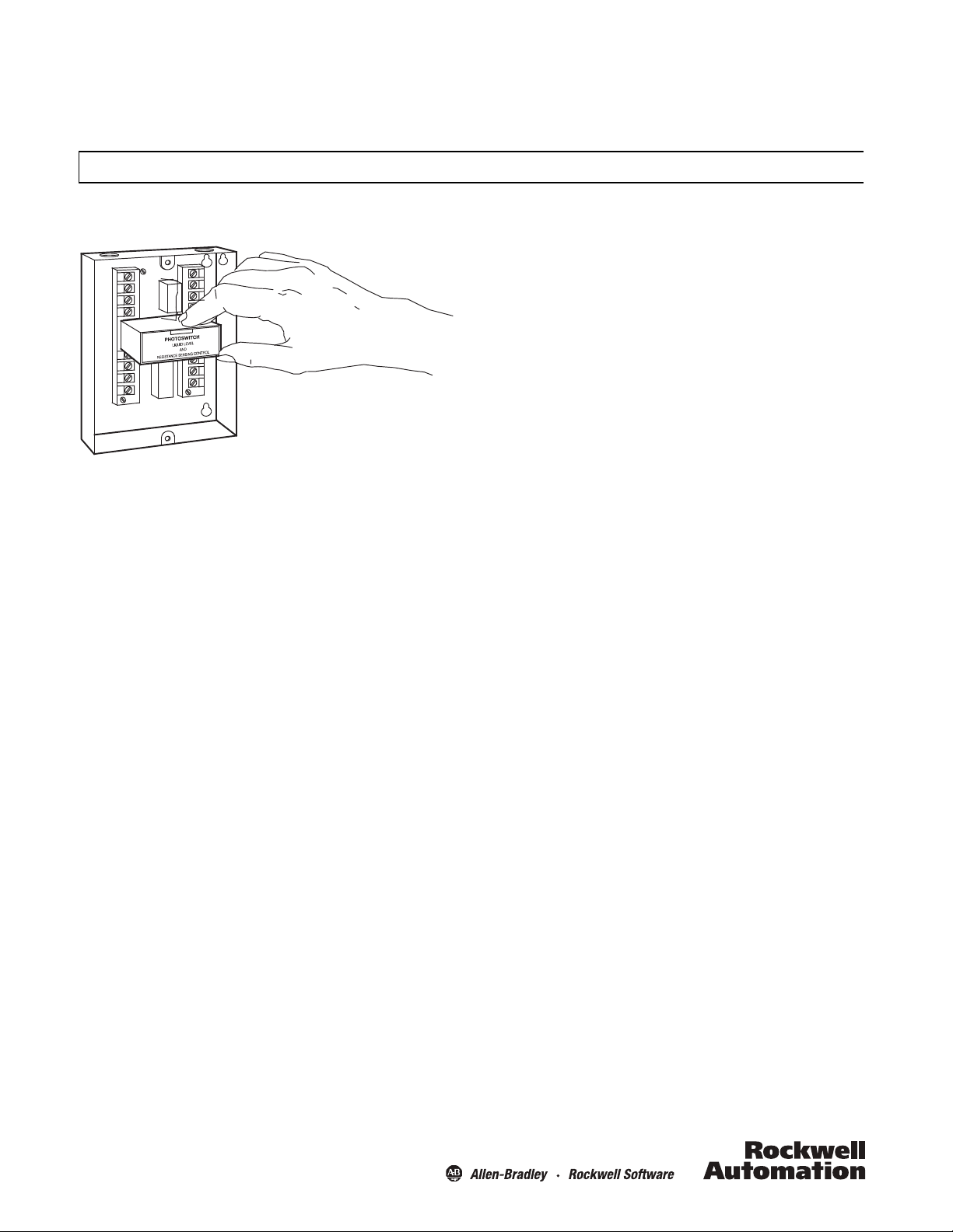
PHOTOSWITCH® Liquid Level and Resistance Sensing Control
Bulletin 13DJ3-3000
low
Product Data
conductivity such
moisture content as
In
addition
can be wired
a
llowing the
A so
simu
electronic counting, da
computer.
The control
transients,
power up. These features a
in solving
to
for
use
lid-state output signal
ltaneous
ly
has protection against false operation due
line
the more
as antibio
low
as
high sens
voltage dropouts
itiv
electronic control
of
both sets
with
a relay output. This signal
ta
difficult industrial level applications
tics, refrigerants,
5%.
ity,
the control
of
relay contacts
can be obtained
logging,
of
llow
the 13DJ3 Series 3000 Control to
has a fast
latching on certain applications,
from
or feeding information to
1/2 second
or
sand
with
response time and
for external loads.
the control
can be used
or
less,
for
to
line voltage
or
during in
.
a
a
be used
itia
l
Descripti
The
Liquid
or so
Feature
on
PHOTOSWITCH
Level Control
lids with
Bulletin
a moisture content as
13DJ3 Series 3000 is a high sensitivi
designed
to
detect the level
low
as
5%.
s
•Very
high sens
•
Compact, all solid state, plug-in, modular design
with fl
•
DPDT
state logic outputs
•Low
probe voltage isolated
•
Fast response
•
Wide selection
•All
molded parts
(PPO) and polystyrene (PS)
•
Heavy-duty easy
•High
•
Ambient temperature range: -40 to 135°F (-40 to 57°C
itiv
ity—up
to
60 megohms cm
exibili
ty
EM
relay and 12V DC solid state outputs.
from
line voltage
tim
e
of
probe assemblie
of
rugged, im
to wire terminals
voltage connections isolated
s
pact resist
from low voltage
General
The
Bulletin
13DJ3 Series 3000 Conductive
designed
solids.
placed
c
rods
(fiberglass, cemen
probe
cause the output relay
pump, valve,
The controls
MegOhmscm. This permits the sensing
to
provide a reliable level detection
No
moving parts
in the
conductive
onductive material
to
the metal material container.
to
complete the electrical circuit. Completion
or
will
or floats are required. Metal probe rods are
liquid
at the desired levels. The
completes the
t,
etc.), an add
to
motor
operate over a resis
itional
operate. The relay contacts may be used
control;
audible and/or visual level indicatio
Liquid
circuit
between the probe rod
If
the container
probe rod
tivity range
of
liquids or
ty
of
conductive
liquid resis
for re
Optional solid
ant polyphenylene oxide
Level Control is
of
conductive
is
non-conductive
is
used as a grounding
of
of 0 to
solids
liquids
tivity
liability
)
liquids or
liquid or so
the
circuit will
60
with
for
very
or
lid
n.
Resistance Sensing Contro
PHOTOSWITCH
sensing control.
s
witch
mechanisms or
capable
sensitiv
megohms
Bulletin
In
which converts the minute current
extremely
of handling rela
ity
of
the
control
.
l
13DJ3
is
also designed
this application the control
flow
light
contacts
into a s
tively heavy electrical
when used
for
resistance sensing
to
be used as a resistance
operates as an electronic
through delicate
witching
loads. The maximum
output
is
15
Page 2
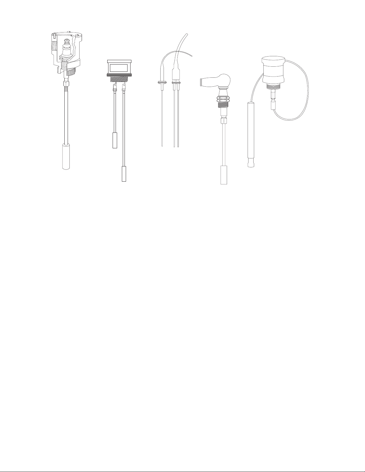
Figure 1: Probes for Level Controls Series 61, 63,
Type 61LF1
probe tting
with Type
64MR1 suspension
wire and tip
Type 61LJ2
probe tting
with
Type 64CR1
probe rods
and tips
Type 63GH1
and 63GH2
sanitary probe
tting and rod
assemblies
Type 61BD1
probe tting
with
Type 64CR1
probe rod
and tip
Type 61LF1
probe tting
with
Type 64CR1
probe rod
and tip
64
Probe Assemblies
A
selection
applications. The probe assembly consists
convenient insta
steel probe rod
desired length
provide the required surface
Figure 1 shows typical probe assemblies.
2
of
probe assemblies
lla
tion into
or
insulated suspension wire
for
the particular insta
a tank, vat,
is
available
or
lla
tion;
area at a point
for
a wide variety
of
a probe
fitting
of
threaded
other container; a stainless
which may be cut
and a probe
of
contact
with
tip
designed
the
to
the
liquid.
for
to
Series 61 probe fittings are ceramic insulated
which
may be used either alone
Sing
le
and double probe fittings are available. Series 63 sanitary probe
f
ittings are
Sanitary probes
Series 64 probe
suspension wire of
available
for
do not require probe tips
tip
assemblies are combinations
the desired length
or in
dairy and other food processing installations.
used with all Series 61 probe fittings
one
of
a variety
for sa
with
a suitable probe
.
with
stainless steel
of metal enclosures.
tisfactory opera
of
a probe rod
tip
trim
tio
n.
or
and are
Page 3
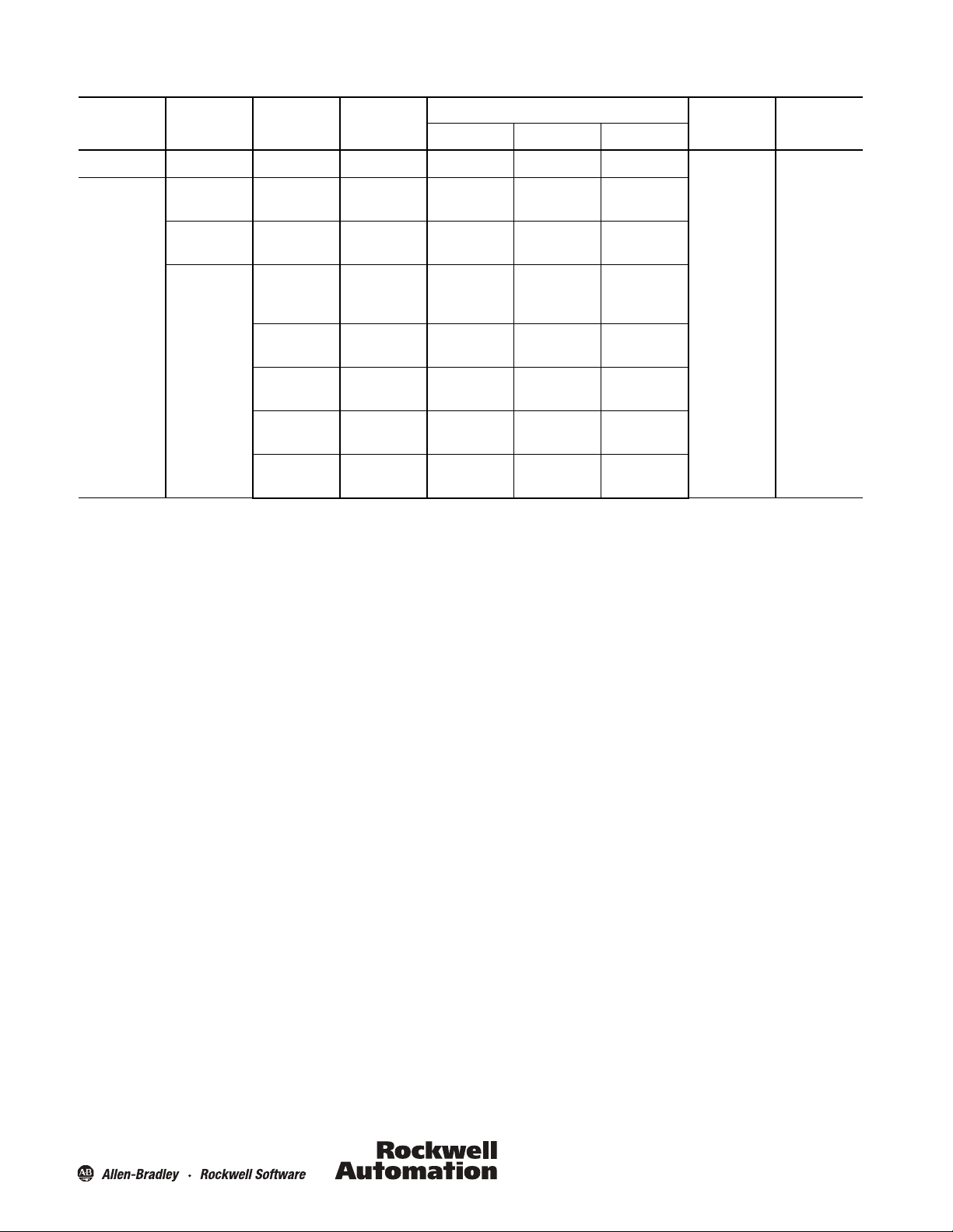
Tab le 1:
Level and Resistance Control
Output Characteristics
Bulletin Number Control Base Output Voltage Supply
13DJ3-3000 — — —
Response Time Resistivity RangeType Rati ng Leak age
60-1600B
60-1601B
8-670
supplied with
control base
8-651
8-652
63-116
63-115
Specifications
Power Consumption:
Resistivity Range:
Resistance Sensing Sensitivity:0--15 MegOhms
Maximum Probe Voltage
Maximum Probe Curren
:
t:
Solid State Output Signal:
Speed
of Response
P
ermissible
Ambient
Temperature
:
Lead Len
gth
:
:
3
watts (includes control base
Typical liquid resis
(See Table
22.5
65
12
0
.003 sec.
Up to
-- 4 0
5)
V A C
(Ranges
mA to 0
.001
V DC
open
circuit limited to
to 0
.20 sec. (See Table
2,000 ft (609.6 m) (See Table
to
135°F (--40
120V AC
50/60 Hz
240V AC
50/60 Hz
———
———
DPDT
EM
Relay
SPNO
TRIAC AC
SPNO
FET AC/DC
Volt age
DC Output
NPN Open
Collec tor
)
tivity 0--60 MegOhms • cen
in six ranges. (See Table
1, 2, &
3), 29
VA C
(Ranges
mA.
(See Table
6)
30mA short
7)
8)
Use #16
to 57°C)
5A, 120V AC
2.5A, 240V AC
1A, 120V DC
1A, 265V AC
20mA min.
30mA,
120V AC/DC
30mA,
24V DC
250mA,
24V DC
timete
r
6,
Consult factory for
4, 5, & 6)
(See Table
circuit.
Terminals #5 and #2 on Control Base
AW G wire minimum
—
1mA
10μA
—
1mA
higher ranges.
6)
Refer to Table 7 Refer to Table 6
)
.
3
Page 4
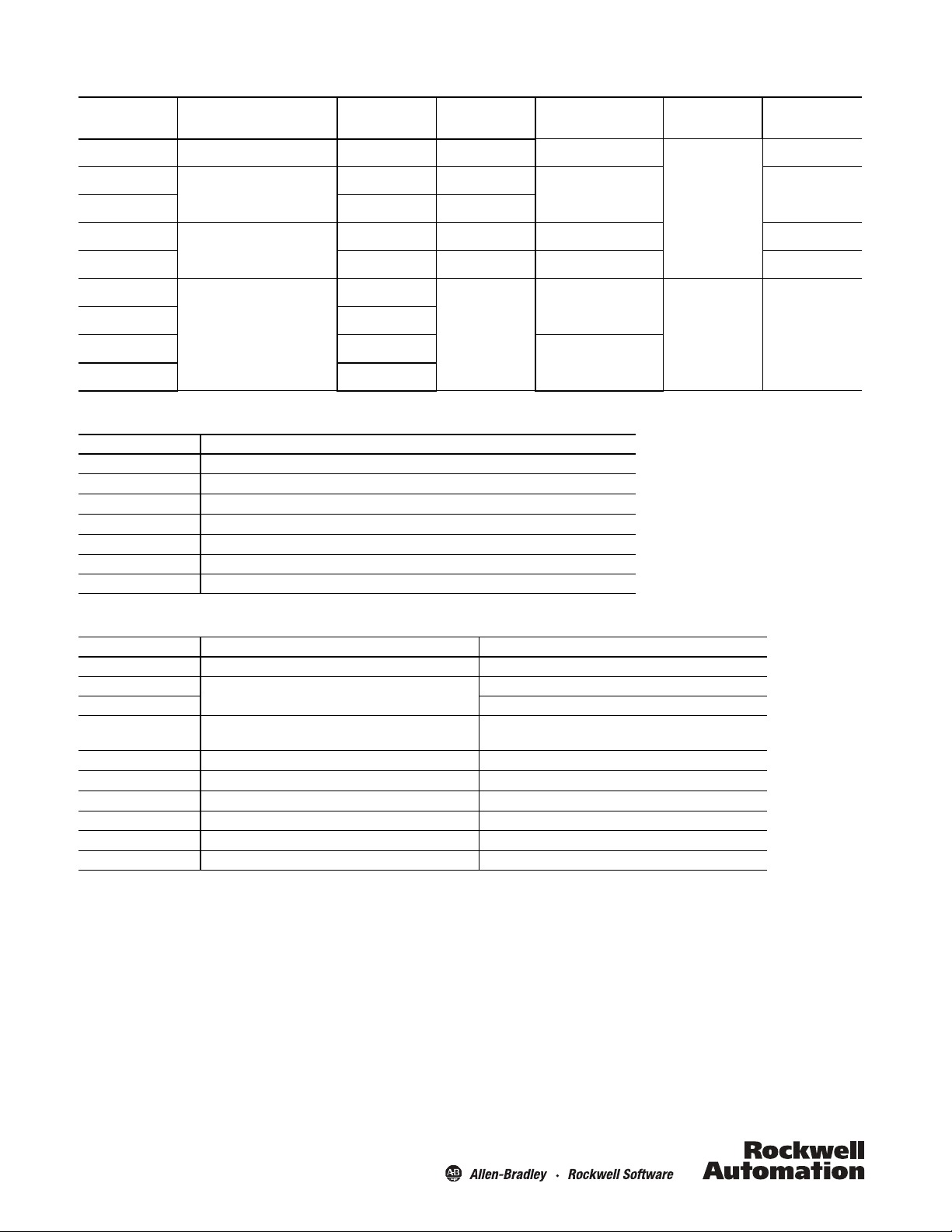
Tab le 2:
Probe Fittings
Bulletin Number Description Rods or Wires Used Housing Material Fitting Pipe Thread
Maximum
Temp era tur e
Maximum Pressure
psi
61BD1-1000 Probe fitting with rubber cap 1 None 1/2 in.
61LF1-1000
61LF1-1000M 316 Stainless Steel
61LJ2-1000
61LJ2-1000 316 Stainless Steel 200 (1,378 kPa)
63GH1-1000
63GH2-1000 2
63GJ1-1000 1
63GJ2-1000 2
Tab le 3:
Probe Rod Assemblies
Bulletin Number Description
64CR164CR164CR164CR164CR164CR164CR1-
Probe fitting in cast enclosure
Two probe fittings in cast enclosure
Special sanitary probe with 3 ft
(0.91m) probe rod(s) supplied with
10ft (3 m) cable and separable
connector
1000
1001
1002
1003
1004
1005
1006
316 Stainless Steel Probe Tip and 1/
316 Stainless Steel Probe Tip and 1/
316 Stainless Steel Probe Tip and 1/
316 Stainless Steel Probe Tip and 1/
316 Stainless Steel Probe Tip and 1/
316 Stainless Steel Probe Tip and 1/
316 Stainless Steel Probe Tip and 1/
4 in.
dia. x
4 in. dia. x
4 in. dia. x
4 in. dia. x
4 in. dia. x
4 in. dia. x
4 in. dia. x
2Bronze
Bronze 2 in. 250 (1,724 kPa)
1
None
12 in. (0.3 m) Probe
24 in. (0.61 m) Probe
36 in. (0.91m) Probe
48 in.
72 in. (1.83 m) Probe
96 in. (2.44 m) Probe
120 in. (3 m) Probe
(1.22 m) Probe
Rod
Rod
Rod
Rod
Rod
Rod
Rod
1 in. 200 (1,378 kPa)
Fits 1 1/2 in. LAMD 13H nut for
#15 Union Ferrule
Fits 2 in. LAMD 13H nut for
#15 Union Ferrule
300°F
149°C
212°F
100°C
250 (1,724 kPa)
—
Tab le 4:
Spare Parts
Part Nu mber Descrip tion Applic ation
3-
170
- 49-
1
21
21
- 50
- 224 1 1/2 in. diameter Teflon
31
33-
287
- 66
58
61-
3284
61-
3285
61
- 3288
61-
3519
Rubber
Cap
Connector and
10 ft (3 m) Cable
1/4-- 20 UNC Hex NutUsed with 64CR1 probe
Insulation Suspension Wir
316 SS 5/8?
diameter Suspension Wire Probe Ti
316 SS
Adap
tor Connects suspension wire to 61 Series pr
316 SS 9/1
6 in. diameter Probe Ti
Resistor
Packa ge
Assembly
Space
r Separates double probes when the long pr
e
p
p
For
61BD1
For 63GH2 -- 63G
For 63GH1 -- 63G
Used when the required probe length exceeds
Used when the required probe length exceeds
Required on all probe rods for rated
For
J2
J1
13DJ3--3000
assemblies
obes
sensitivi
obe
ty
exceeds
10 ft (3 m)
10 ft (3 m)
30 in. (76.2 cm)
4
Page 5
61BD1 Model 1000
also used in
61LF1- 61LJ2
all models
PROBE ROD
*PART NO.
31-- 224
1/2 in. NPT
PART NO. 33--287
NO. 3--170
RUBBER CAP
Suspension wire
adaptor and probe tip
assembly
SUSPENSION WIRE
ADAPTOR
NO. 61--3285
SUSPENSION WIRE
NO. 58--66
ORDER SEPARATELY
AND SPECIFY
REQUIRED LENGTH
Figure 2
*AVAILABLE AS OPTIONAL EXTRA WITH
DOUBLE PROBE ASSEMBLIES, WHEN
EITHER ROD EXCEEDS 30 INCHES
IN LENGTH.
PROBE TIP
NO. 61--3288
PROBE TIP ASSEMBLY
See Table 4 for further
description.
NO. 61--3284
5
Page 6

Tab le 5:
Typical Control Ranges and Probe Materials
Typic al Liqui d
Acetate Aci
d5
Ammonia6
Ammonium Chlori
Ammonium Iodi
Ammonium Nitrat
Ammonium Sulfate
Antibiotics
Barium Chlori
Barium Nitrat
Bee
Butyric Aci
Cadium Bromi
Cadium Chlori
Cadium Iodi
Cadium Nitrat
Cadium Sulfat
Calci um Chlori
Calci um Nitrat
Copper Chlori
Cupric Nitrat
Cupric Sulfat
Distilled Water
Formic Aci
Hydrobromic Aci
Hydrochloric Aci
Hydrofluoric Aci
Hydroiodic Aci
Lead Nitrat
Lithium Car
Lithium Chlori
Lithium
Lithium Iodi
Lithium Sulfat
Magnesium Chlori
Magnesium Nitrate
Magnesium Sulfate
Mercuric Bromi
Mil
Nitric Aci
Oxalic Aci
Phosphoric
Potassium
Potassium Bromi
Potassium Car
Potassium Chlori
Potassium
Potassium Fluori
Potassium
Potassium Iodi
Potassium Nitrat
Potassium Oxalat
Potassium Sulfat
de 5--25 2--10
de 10--50 2--12
e5
de 10--25 5--15
e4
r
d1
de 5--30 35--100
de 5--50 30--60
de 5--45 30--160
e5
e5
de 5--35 5--15
e6
de 10--35 10--15
e10
e
d5
d5
d5
d5
d
e20
bona
te
de 5--40 5--15
Hydroxide 1.25--7
de 10--25 5--20
e
de 5--28 10--20
de 0.223--0.422 40,000--60,000
k 200--2,000
d5
d3
Acid 10--87 5--20
Acetate10
de 10--36 2--10
bona
te
de 5--20 4--18
Cyanide 3--61
de 5--40 5--15
Hydroxide 5--40 2--5
de 10--55 5--18
e10
e
e
Concentration
(% by weight)
--
50 600--1,300
.4--
15 1,000--2,000
--
50 3--20
5--30 5--20
.2--8.4
--
20 1,000--2,000
--
48 10--20
--
36 20--70
--
50 10--20
--
35 10--15
2.5--17.5
--
60 100--200
--
15 2--5
--
40 1--5
--
30 3--20
58 1 SS
--
30 15--20
0
.2
.5
525 1 SS
10--17 10--12
5--25 20--40
--
60 1--5
.5--
712
--
30 4--18
5--50 5--20
--
20 5--12
10 11 1 SS
10 12 1 M
Resistivity Range
(ohms cm
)
200,000-- 2 M
Ω
30--50
200--2,000
20--100
20,000--200,000
300 1 SS
4--12
--
20
--
20
Control Range
2HC
2SS
1
1SS
1SS
1HC
5SS
1SS
1SS
1 or 2 SS
2SS
1SS
1SS
1SS
1SS
1SS
1SS
1SS
1
1SS
1SS
3SS
1SS
1HB
1HB
1
1SS
1SS
1SS
1SS
1M
1SS
1SS
3SS
1 or 2 SS
1SS
1SS
1HC
1SS
1SS
1SS
1SS
1SS
1SS
1M
1SS
1SS
Suitable Probe
Material
HB,
HC
HB,
HC
M,
HC
6
Page 7

Table 5: Typical Control Ranges and Probe Materials (continued
)
Typic al Liqui d
Potassium Sulfi
Propionic
Re
Silver Nitrat
Sodium
Sodium Car
Sodium Chlori
Sodium
Sodium Iodi
Sodium Nitrat
Sodium Sulfate
Sodium Sulfi
Strontium Chlori
Strontium Nitrat
Sulfuric Aci
Synthetic Late
Ta p w ate
Zinc Chlori
Zinc Sulfate
de 5--50 2--10
Acid 5--30 900--1,200
frigerant
s2
e10
Acetate20
bona
te
de 5--25 5--15
Hydroxide 20--50 5--20
de 10--40 5--20
e10
de 2--18 5--20
de 10--20 5--12
e10
d5
x2
r
de 10--40 10--15
Measured at normal room temperatur
Suitable probe materials
SS = 316 stainless steel (standard)
M = Monel
HB = Hastelloy B2
HC = Hastelloy C
Concentration
(% by weight)
--
60 5--20
--
30 15--18
5--15 10--20
--
30 7--12
10--15 8--12
--
40 10--15
--
50 1--10
5--30 20--100
e
Resistivity Range
(ohms cm
)
MΩ--20M
Ω
MΩ--20M
Ω
2,000--20,000
Control Range
1SS
2M
5 or 6 SS
1SS
1SS
1SS
1SS
1M
1SS
1SS
1SS
1SS
1SS
1SS
1HC
6SS
3SS
1M
1SS
Suitable Probe
Material
Tab le 6:
Level and Resistance Sensing Ranges
Liquid Resistivity
Range
1
2
3
4
5
6
0 --
600
600 -- 6,0
6,000 -- 60,0
60,000 --
.6MΩ -- 6M
6MΩ -- 60M
ohms
00
0.6M
Resistance
/cm
00
Ω
Ω
Ω
Sensing
0 --
150
Ω
150 -- 1,500Ω
1,500 -- 15,000Ω
15,000 --
150,000
150,000 -- 1.5M
1.5 -- 15M
Ω
Ω
Ω
Or
ange
Or
ange
Brown
330
Ω
Red
Viole
Red
2,700
Ω
Red
Viole
Or
ange
,000Ω
27
Red
Viole
Yellow
270
,000Ω
Red
Viole
Gr
een
2
.7M
Ω
Red
Viole
Blue
M
Ω
27
Range
Resistor
t
t
t
t
t
22.5
22.5
22.5
29
29
29
V AC
V AC
V AC
V DC
V DC
V DC
Maximum
Volts
Maximum
Current
65 m
AAc
8.33 m
ABee
0.83 m
A
0.1 mA
0.01 m
A
0.001 m
A
Typic al
Solutions
i
ds Bases Salts
r Milk Wat e r
Water Al
cohols
Wat e r
Alcohols Ammonia
Wat e r
tibioti
cs
An
Re
frigerant
Re
frigerants
Synthetic
Distilled
Distilled
s
Latex
Note:
All range resistors are 1/2 W ±
10% except Range
1, which is
2 W.
7
Page 8

Tab le 7:
Speed of Response (sec
Range
1
2
3
4
5
6
Ordering Instruct
onds)
Solid-State Outputs
O
N
0.0
03
0.0
035
0.0
04
0.0
06
0.0
23
0.1
90
ions
O
FF
0.0
60
0.0
60
0.0
60
0.0
60
0.0
60
0.1
90
1. Select 13DJ3--3000
2. Select Control Base
Bulletin Numbers Voltage Supply Description
60-
1600
B
60
- 1610
B
60
- 1601
B
60
- 1611
B
For NEMA 3, 4, 12, and 13; order open type
3.
Select Probe Fittin
Bulletin Number
61BD1-
1000
61LF1-
1000
LF1- 1000
61
61LJ2-
1000
61LJ2-
1000
Note
: 61 Series probe fittings require suitable Series
63GH1-
1000
63GH2-
1000
63GJ1- 1000
63GJ2- 1000
4.
Select Probe
Bulletin Number
64CR1-
1000
64CR1-
1001
64CR1-
1002
64CR1-
1003
64CR1-
1004
64CR1-
1005
64CR1-
1006
50/60
50/60
M
M
Rod Assemblies
Probe Tip and 1/
Probe Tip and 1/
Probe Tip and 1/
Probe Tip and 1/
Probe Tip and 1/
Probe Tip and 1/
Probe Tip and 1/
120
VA C
230
VA C
g
Probe fitti ng with rubber
Probe fitti ng in
Two probe fittings in cast
Special sanitary pr
probe
cable
Open
Ty p e
Hz
NEMA 1
Enclosure
Open
Ty p e
Hz
NEMA 1
Enclosure
base
and 61--4090
enclosure
.
Description
cap
cast enclosure
enclosure
64
probe tips and probe rod or suspension wires shown below.
obe
with
rod(s) supplied with 10 ft
and
separable
4 in. dia. x
4 in. dia. x
4 in. dia. x
4 in. dia. x
4 in. dia. x
4 in. dia. x
4 in. dia. x
3 ft (0.91 m)
(3 m)
connecto
r
for
61 Series Probe Fittin
Description
12 in. (0.3 m) Probe
24 in. (0.61 m) Probe
36 in. (0.91 m) Probe
48 in. (1.22 m) Probe
72 in. (1.83 m) Probe
96 in. (2.44 m) Probe
120 in. (3 m) Probe
Rod
Rod
Rod
Rod
Rod
Rod
Rod
O
N
0.0
0.0
0.0
0.0
0.0
0.2
Relay Output
12
13
14
18
33
00
Rods or
Wires Used
1
2
1
2
1
2
gs
Installati
The control
O
FF
0.0
70
0.0
70
0.0
70
0.0
70
0.0
70
0.2
00
or
the probe rod. Rods may be ordered
than required and cut
threaded
should be inserted in
For deep well
suspension
613288,
insulating
The probe rod
probe
61 Series fittings have a 1/4--20 female
thread
When the long probe
(0.76m), a Teflon
rod
For
tip to
Series 63 sanitary probes
made for special sanitary fittings.
union ferrule
nut
secured before
f
it
Series
the
on
point
for liquid level
breaks contact
with
the probe
to
for
connection
the probe
and other long probe applications over 10 ft (3 m),
wires and tips should be installed. Standard probe
is
used
with all probe rods. Special probe
sleeve,
is used with s
or
suspension wire
fitting
as fo
llows
:
of
the probe rod
or
of
any multiple probe assembly
insulating
immediately above the probe
suspension wire
prevent
are
supplied
1--1/2 in. ferrule,
63
probe rods are
assemblies, an insulating
it from
touching other surfaces
and
to
be secured
by
the customer and are soldered, brazed,
insertion
of
while
3 ft (0.91 m) long and are
job.
is
the point at which the
tip
and
is
to
size,
the desired length. One end
to
the probe
tip
fitting.
and held
uspension wir
adaptor 61--3285
thread
suspension wire adaptor
spacer 31--224,
tip to
prevent the rods
for
dairy and food
The probe insulator
with
a #13H union nut. The ferrule
the probe assembly. Probes 63GH1 and 63GH2
probes 63GJ1 and 63GJ2
liquid
determined
or
may be supplied longer
by
of
the rod
the length
is
The unthreaded (cut) end
by
means
of
a set screw.
tip
tip
61--3284
with
e.
is
connected
to
receive the 1/4--20 ma
to the
.
is
over
30 in.
is fitted
over the short probe
from
touching.
sleeve
fits
over the probe
.
indus
try
applications are
is
made
to fit
or
otherwise
fit a 2 in. ferrule.
to
be cut
to
length on
makes
of
le
a #15
and
All
Mounting
The 13DJ3 controls may be mounted
par
titio
n, panel board, bracket,
enclosure
place
is
being mounted, the control base should be stored
to avoid
moisture and mechanical damage
The enclosure mounting hole dimensions are shown on
sheet metal, wood
use
d.
When the housing has been securely fastened,
conduits
to
or
machine screws, bolts,
the housing
in
the knock out holes provided and replace the
control base.
The
wiring
between the control
lengths listed below.
Tab le 8:
Maximum Recommended Cable Lengt
Range
1
2
3
4
5
6
Cable Length
2000 ft (
1000 ft (
500 ft (
2000 ft (
2000 ft (
150 ft (45.7 m)
in
any position
or similar support.
on a sturdy wa
While
the
NEMA
in a safe
.
page 12
or similar fasteners
may be
connect the cables
and the probes should not exceed the
h
609
.6 m)
304
.8 m)
152
.4 m)
609
.6 m)
609
.6 m)
and
ll,
or
8
Page 9

Resistor Selecti
ATTENTION
Do not
run probe
or
reset leads
in
same
conduit with
power lines
or high
current
carrying c
onductors.
.188
(4.8)
NEMA 1 #61- 3322- 3
3.938
(100)
.875 (22.2)
5.25
(133.4)
5.938
(150.8)
7.25
(184.1)
4.875
(123.8)
.375
(9.5)
.688
(17.5)
5.938
(150.8)
.812
(20.6)
3.875
(98.4)
.375
(9.5)
.875 DIA. ( 22.2)
8 K.0.’S TOTAL
*
*
*
*
TYP.
1.188
(30.2)
1.063
(27)
*
*
NEMA 3, 4, 5, 12 & 13
#61- 4090
4
(101.6)
8.75
(222.2)
9.5
(241.3)
.375
(9.5)
6.25
(158.7)
4.875
(123.8)
.625 (15.9)
.312 (7.9)
HOLE (4)
8.25
(209.5)
When the resis
select
the range resistor that corresponds
tivity
on
of
the
liquid is
known, convert
to
the resis
5.
When the resis
probe
For operation
connect
s
hou
ld
until the relay energizes.
tivity
of
the
tip
1/16 in. (1.5 mm)
with
the relay energized
the
Range 1 resistor (330 ohms)
energize.
If it
does not, use successively higher range resistors
If
liquid is
not known, immerse the high level
into
the
liquid.
relay action
with
the probe immersed,
to
Ter m i n a l s 1 and
is
sluggish, use the next higher
range resistor.
For operation
c
onnect the Range 1 resistor (330 ohms)
s
hou
ld
until the
range res
Note:
with
the relay de-energized
de-energize.
If it
relay de-energizes.
does not, use successively higher range resistors
If
relay action
with
to
Ter m i n a l s 1 and
is
sluggish, use the next higher
istor.
For resistance sensing applications, use the values of
resistance sensing sensitivity listed in Table
probe circuit resistivity for selection
resistor.
Note:
Wiring for
Ranges 1--2--3 differs from
wiring instructions in Wiring Diagrams
to
ohms • cm and
tivity range
2.
The relay
in
the probe immersed,
3.
The relay
6 in place of
of
the proper r
Ranges
ange
4--5--6. Follow
in Figures 6--11.
Ta b l e
Outline and Mounting Dimension
Unless otherwise indicated, dimensions shown are
parentheses are
in millimeters
.
s
in
inches. Those
in
Wiring
All external wiring
applicable local
Wire
no smaller than 16
Since the 13DJ3 control operates
resistance, the insulation
the probe must be extremely high.
to
plas
tic
insulated wire to
moisture
with
probes are furnished
cable assembly
or crack and permit leakage paths
paper,
should conform
codes. See
wiring
AWG is recommende
resistance
to
diagrams
with
liquids
of
the
It is
the Na
tional
for external
d.
having high electrica
wiring
important, therefore,
insure that the insulation will
to
develop. Wires insulated
cotton,
asbestos, etc. must not be used. Series 63 sanitary
with
a molded separable connector and
.
Electric Code and
connections.
l
connecting the control
to
use
not absorb
10 ft (3 m)
Figure 3
Figure 4
9
Page 10

Figure 5
Open Type
5.25
(133.3)
4.781
(121.4)
.25
.031
(.8)
1.25
(31.7)
2.5
(63.4)
3.125
(79.4)
.531
(13.5)
EITHER MAY BE USED FOR
THIRD MOUNTING HOLE
#8 SCREW
TERMINALS
(16)
4 MTG. HOLES
.185 DIA.
(2.54)
2.375
(60.3)
2.25
(57.1)
3.625
(92.1)
WITH INSTALLED PLUG-IN MODULE
.375
(9.5)
Low Level Alarm
INC
IN0
IC
L1
2NC
2N0
2C
L2
13DJ3-- MODEL 3000
PLUG-IN
CONTROL MODULE
1
2
3
4
8
7
0
5
LINE VOLTAGE
ALARM
RANGE
RESISTOR
Single probe low level alarm. The relay is de-energized with
probe immersed and energized with probe out of liquid.
Connections are shown for operation on ranges 1, 2 & 3.
For operation on ranges 4, 5 & 6, connect range resistor to
terminal “4” instead of terminal “3.”
Tank must be grounded
Low Level Alarm
Self-Latching with Push Button Reset
Tank must be grounded
INC
IN0
IC
L1
2NC
2N0
2C
L2
13DJ3-- MODEL 3000
PLUG-IN
CONTROL MODULE
1
2
3
4
8
7
0
5
LINE VOLTAGE
ALARM
RANGE
RESISTOR
Single probe low level alarm with electronic latching & push
button reset. The relay is de-energized with probe immersed
and energized with probe out of liquid. Connections are shown
for ranges 1, 2 & 3. For operaion on ranges 4, 5 & 6, connect
range resistor to terminal “4” instead of terminal “3.”
N.C. RESET
SWITCH
Typical Series 13DJ3 Wiring Diagrams
Figure 6
10
Figure 7
Page 11

Figure 8
High Level Alarm
INC
IN0
IC
L1
2NC
2N0
2C
L2
13DJ3-- MODEL 3000
PLUG-IN
CONTROL MODULE
1
2
3
4
8
7
0
5
LINE VOLTAGE
ALARM
RANGE
RESISTOR
Single probe high level alarm. The relay is de-energized with
probe immersed and energized with probe out of liquid.
Connections are shown for operation on ranges 1, 2 & 3.
For operation on ranges 4, 5 & 6, connect range resistor to
terminal “4” instead of terminal “3.”
Tank must be grounded
+
--
SOLID
STATE
OUTPUT
12 V MIN
High Level Alarm
Self-Latching with Push Button Reset
Tank must be grounded
INC
IN0
IC
L1
2NC
2N0
2C
L2
13DJ3-- MODEL 3000
PLUG-IN
CONTROL MODULE
1
2
3
4
8
7
0
5
LINE VOLTAGE
ALARM
RANGE
RESISTOR
Single probe high level alarm with electronic latching & push
and energized with probe out of liquid. Connections are shown
for ranges 1, 2 & 3. For operation on ranges 4, 5 & 6 connect
range resistor to terminal “4” instead of terminal “3.”
N.C. RESET
SWITCH
Pump Up Constant Level Control
INC
IN0
IC
L1
2NC
2N0
2C
L2
13DJ3-- MODEL 3000
PLUG-IN
CONTROL MODULE
1
2
3
4
8
7
0
5
LINE VOLTAGE
PUMP
RANGE
RESISTOR
A double probe installation, used for pump-up constant level
control. The relay is de-energized when the upper probe is
immersed and does not energize until the liquid drops below
the lower proble. Connections are shown for ranges 1, 2 & 3.
For operation on ranges 4, 5 & 6 connect range resistor to
terminal “4” instead of terminal “3.”
Tank must be grounded
+
--
SOLID
STAT E
OUTPUT
12 V MIN
Figure 10
Pump Down Constant Level Control
LINE VOLTAGE
Figure 9
PUMP
INC
IN0
IC
L1
2NC
2N0
2C
L2
13DJ3-- MODEL 3000
PLUG-IN
CONTROL MODULE
RANGE
RESISTOR
1
2
3
4
8
7
0
5
A double probe installation, used for pump-down constant
level control. The relay is energized when the upper probe is
immersed and de-energized when the liquid drops below the
lower proble. Connections are shown for ranges 1, 2 & 3. For
operation on ranges 4, 5 & 6, connect ground to terminal “4”
instead of terminal “3.”
For insulated tanks, a grounded third probe must
must be added as shown. If an additional wire is
run between the control ground and the third probe,
it should be grounded at the control.
Figure 11
11
Page 12

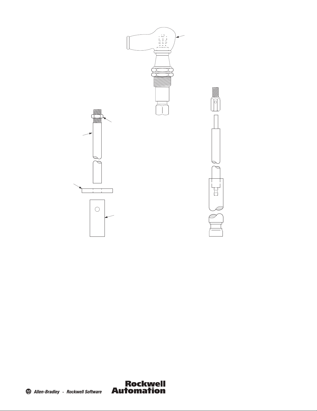
61 Series Probe Assemblies
Pump Down Constant Level Control
INC
IN0
IC
L1
2NC
2N0
2C
L2
13DJ3-- MODEL 3000
PLUG-IN
CONTROL MODULE
1
2
3
4
8
7
0
5
LINE VOLTAGE
PUMP
RANGE
RESISTOR
A double probe installation, used for pump-down constant
level control. The relay is energized when the upper probe is
immersed and de-energized when the liquid drops below the
lower probe. Connections are shown for ranges 1, 2 & 3. For
operation on ranges 4, 5 & 6, connect range resistor to terminal
“4” instead of terminal “3.”
For insulated tanks, a grounded third probe
must be added as shown. If an additional wire
is run between the control ground and the
third probe, it should be grounded at the
control.
1.812 (46)
3.5
(88.9)
.5 (12.7)
1
(25.4)
1/2--14 NPT
1/4--20 NC2
.375 (9.5)
1/2--14
NPSC
WEEP HOLES
(3)
VIEW WITH
COVER REMOVED
2.125 DIA.
(54)
1.812
(46)
2.437
(61.9)
2.438
(61.9)
LH
VIEW WITH
COVER REMOVED
3.125 DIA.
(76.2)
1/2--14
NPSC
2.875 DIA.
(73)
.812 (20.6)
61BD1
Figure 12
Figure 11
A
12
1--11 1/2
NPT
.625 (15.9)
61LF1
63 Series Probe Assemblies
#13--H UNIONNUT
(SUPPLIED BY CUSTOMER)
POLARIZED
CONNECTOR
(TO PREVENT
INTERCHANGING
OF PROBE WIRES)
PROBE
INSULATOR
#15 UNION FERRULE
(SUPPLIED BY CUSTOMER)
SOLDER FERRULE
TO TANK FOR
MOUNTING
FITTING
INSULATOR
(TO PREVENT
PROBE RODS
FROM TOUCHING)
Type 63GJ1
63GH1
Figure 13
.625 (15.9)
Type 63GJ2
63GH2
61LJ2
PROBE WIRE
TO CONTROL
*NOTE:
FOR TYPES 63GJ1
AND 63GJ2
USE 2 FITTINGS
FOR TYPES 63GH1
AND 63GH2
USE 1 1/2 FITTINGS
PROBE
(CUT TO LENGTH
ON INSTALLATION)
2--11 1/2
NPT
Page 13

Figure 14
2
(50.8)
1.125
(28.6)
.562 DIA.
(14.3)
.25 DIA.
(6.35)
1/4--20 UNC
.75
(19)
“A” DIM.
6
(152.4)
61--3284
.875 DIA. (22.2)
PROBE TIP
NO. 316 S.S.
INSULATED
1.25
(31.8)
.312 (7.9)
61--3285
ADAPTER
NO. 316 S.S.
7/16 HEX (11.1)
58--66
.281 DIA. (7.1)
NO. 16 S.S. WIRE,
INSULATED
WITH GEON
LENGTH TO BE
SPECIFIED BY
CUSTOMER
64CR1
1/4-- 20 NC2
HEX NUT,
NO. 316 S.S.
64 Series Probe Assemblies
13
Page 14

14
Page 15

15
Page 16

13DJ-2.0 Ver 02
February 2013
Printed in USA
 Loading...