

Page 1
IQ Master™
Version 3.2.4
for
IQ-2000 and IQ-5000
Positioning Drive
Modules,
IQ-550 Position
Control Module,
and ULTRA Plus™
Positioning Drive
Modules
Programming Manual
Page 2

Important User Information
Because of the variety of uses for the products described in this publication, those
responsible for the application and use of this control equipment must satisfy
themselves that all necessary steps have been taken to assure that each application
and use meets all performance and safety requirements, including any applicable
laws, regulations, codes and standards.
The illustrations, charts, sample programs and layout examples shown in this guide
are intended solely for purposes of example. Since there are many variables and
requirements associated with any particular installation, Allen-Bradley
assume responsibility or liability (to include in tellectual property liability) for
actual use based upon the examples shown in this publication.
Allen-Bradley publication SGI–1.1, Safety Guidelines for the Application,
Installation and Maintenance of Solid-State Control (available from your local
Allen-Bradley office), describes some important differences between solid-state
equipment and electromechanical devices that should be taken into consideration
when applying products such as those described in this publication.
®
does not
Reproduction of the contents of this copyrighted publication, in whole or part,
without written permission of Rockwell Automation
Throughout this manual we use notes to make you aware of safety considerations
ATTENTION
Identifies information about practices or
circumstances that can lead to personal injury or
®
, is prohibited.
death, property damage or economic loss
!
Attention statements help you to:
• identify a hazard
• avoid a hazard
• recognize the consequences
IMPORTANT
Identifies information that is critical for
successful application and understanding of the
product.
:
Allen-Bradley and IQ-Series are registered trademarks of Rockwell Automation.
IQ Master and ULTRA Plus are trademarks of Rockwell Automation.
Microsoft is a registered trademarks of Microsoft Corporation.
Windows is a trademark of Microsoft Corporation.
Page 3

Table of Contents
Preface . . . . . . . . . . . . . . . . . . . . . . . . . . . . . . . . . . . . . . . . . . . . . . . . . . . . . . 1
Introduction . . . . . . . . . . . . . . . . . . . . . . . . . . . . . . . . . . . . . . . . . . . . . . . . . . . . . . . . . . . . . . 1
Who Should Use this Manual . . . . . . . . . . . . . . . . . . . . . . . . . . . . . . . . . . . . . . . . . . . . . . . . 1
Where to Find Help . . . . . . . . . . . . . . . . . . . . . . . . . . . . . . . . . . . . . . . . . . . . . . . . . . . . . . .1
Contents of this Manual . . . . . . . . . . . . . . . . . . . . . . . . . . . . . . . . . . . . . . . . . . . . . . . . . . . .2
Related Documentation . . . . . . . . . . . . . . . . . . . . . . . . . . . . . . . . . . . . . . . . . . . . . . . . . . . . 3
Conventions Used in this Manual . . . . . . . . . . . . . . . . . . . . . . . . . . . . . . . . . . . . . . . . . . . . . 3
Using Online Help . . . . . . . . . . . . . . . . . . . . . . . . . . . . . . . . . . . . . . . . . . . . . . . . . . . . . . . . 4
Allen-Bradley Support . . . . . . . . . . . . . . . . . . . . . . . . . . . . . . . . . . . . . . . . . . . . . . . . . . . . .5
Local Product Support . . . . . . . . . . . . . . . . . . . . . . . . . . . . . . . . . . . . . . . . . . . . . . . . . 5
Technical Product Assistance . . . . . . . . . . . . . . . . . . . . . . . . . . . . . . . . . . . . . . . . . . . . 5
Introduction to IQ Master . . . . . . . . . . . . . . . . . . . . . . . . . . . . . . . . . . . . . . . 3
About the Allen-Bradley IQ Master Manual . . . . . . . . . . . . . . . . . . . . . . . . . . . . . . . . . . . . . 3
ULTRA Plus or IQ-Series System Overview . . . . . . . . . . . . . . . . . . . . . . . . . . . . . . . . . . . . 4
IQ Master . . . . . . . . . . . . . . . . . . . . . . . . . . . . . . . . . . . . . . . . . . . . . . . . . . . . . . . . . . . 6
IQ-550 Position Control Module . . . . . . . . . . . . . . . . . . . . . . . . . . . . . . . . . . . . . . . . . . 6
Positioning Drive Modules (PDM) . . . . . . . . . . . . . . . . . . . . . . . . . . . . . . . . . . . . . . . . . 6
PDMs with Integral Power Supply Modules . . . . . . . . . . . . . . . . . . . . . . . . . . . . . . . . 6
PDMs with Separate Power Supply Modules . . . . . . . . . . . . . . . . . . . . . . . . . . . . . . 6
Power Supply Module (PSM) . . . . . . . . . . . . . . . . . . . . . . . . . . . . . . . . . . . . . . . . . . . . 6
Motors . . . . . . . . . . . . . . . . . . . . . . . . . . . . . . . . . . . . . . . . . . . . . . . . . . . . . . . . . . . . . . 7
Operator Terminal . . . . . . . . . . . . . . . . . . . . . . . . . . . . . . . . . . . . . . . . . . . . . . . . . . . . . 7
Personality Module (PM) . . . . . . . . . . . . . . . . . . . . . . . . . . . . . . . . . . . . . . . . . . . . . . . . 7
Manuals . . . . . . . . . . . . . . . . . . . . . . . . . . . . . . . . . . . . . . . . . . . . . . . . . . . . . . . . . . . . 7
Option Cards . . . . . . . . . . . . . . . . . . . . . . . . . . . . . . . . . . . . . . . . . . . . . . . . . . . . . . . . . 7
Publication 1398-PM601A-EN-P — October 2000
Page 4

iv
Memory and I/O Expansion Card . . . . . . . . . . . . . . . . . . . . . . . . . . . . . . . . . . . . . . . 8
I/O Expansion Card . . . . . . . . . . . . . . . . . . . . . . . . . . . . . . . . . . . . . . . . . . . . . . . . . . 8
Personal Computer (PC) . . . . . . . . . . . . . . . . . . . . . . . . . . . . . . . . . . . . . . . . . . . . . . . . 8
Symbols and Conventions . . . . . . . . . . . . . . . . . . . . . . . . . . . . . . . . . . . . . . . . . . . . . . . . . . 8
Minimum Personal Computer Requirements . . . . . . . . . . . . . . . . . . . . . . . . . . . . . . . . . . . . 9
IQ Master . . . . . . . . . . . . . . . . . . . . . . . . . . . . . . . . . . . . . . . . . . . . . . . . . . . . . . . . . . . 9
New Features . . . . . . . . . . . . . . . . . . . . . . . . . . . . . . . . . . . . . . . . . . . . . . . . . . . . . . . . . . . 10
New in Version 3.2.4 vs. Version 3.2.3 . . . . . . . . . . . . . . . . . . . . . . . . . . . . . . . . . . . . 10
New in Version 3.2 vs. Version 3.0 . . . . . . . . . . . . . . . . . . . . . . . . . . . . . . . . . . . . . . . 10
New in Version 3.0 vs. Version 2.1x . . . . . . . . . . . . . . . . . . . . . . . . . . . . . . . . . . . . . . 10
New in Version 2.1 vs. Version 2.0 . . . . . . . . . . . . . . . . . . . . . . . . . . . . . . . . . . . . . . . 10
New in Version 2.x vs. Version 1.x . . . . . . . . . . . . . . . . . . . . . . . . . . . . . . . . . . . . . . . 10
Quick Start Check List . . . . . . . . . . . . . . . . . . . . . . . . . . . . . . . . . . . . . . . . 12
Introduction . . . . . . . . . . . . . . . . . . . . . . . . . . . . . . . . . . . . . . . . . . . . . . . . . . . . . . . . . . . . . 12
Quick Start Check List . . . . . . . . . . . . . . . . . . . . . . . . . . . . . . . . . . . . . . . . . . . . . . . . . . . . 12
Getting Started with IQ Master . . . . . . . . . . . . . . . . . . . . . . . . . . . . . . . . . 15
Hardware and Software Requirements . . . . . . . . . . . . . . . . . . . . . . . . . . . . . . . . . . . . . . . 15
Using Windows Without a Mouse - A Quick Review . . . . . . . . . . . . . . . . . . . . . . . . . . . . . 15
Windows Hot Keys . . . . . . . . . . . . . . . . . . . . . . . . . . . . . . . . . . . . . . . . . . . . . . . . . . . 15
IQ Master Hot Keys . . . . . . . . . . . . . . . . . . . . . . . . . . . . . . . . . . . . . . . . . . . . . . . . . . . 17
Using the IQ Master Setup Program . . . . . . . . . . . . . . . . . . . . . . . . . . . . . . . . . . . . . . . . . 17
The Readme File . . . . . . . . . . . . . . . . . . . . . . . . . . . . . . . . . . . . . . . . . . . . . . . . . . . . . . . .18
Starting and Quitting IQ Master . . . . . . . . . . . . . . . . . . . . . . . . . . . . . . . . . . . . . . . . . . . . .19
To Start IQ Master . . . . . . . . . . . . . . . . . . . . . . . . . . . . . . . . . . . . . . . . . . . . . . . . . . . 19
The IQ Master Screen . . . . . . . . . . . . . . . . . . . . . . . . . . . . . . . . . . . . . . . . . . . . . . . . . 19
Quitting IQ Master . . . . . . . . . . . . . . . . . . . . . . . . . . . . . . . . . . . . . . . . . . . . . . . . . . . . 19
On-line Help . . . . . . . . . . . . . . . . . . . . . . . . . . . . . . . . . . . . . . . . . . . . . . . . . . . . . . . . . . . . 20
To Start Help: . . . . . . . . . . . . . . . . . . . . . . . . . . . . . . . . . . . . . . . . . . . . . . . . . . . . . . . 20
Upgrading from Version 1 . . . . . . . . . . . . . . . . . . . . . . . . . . . . . . . . . . . . . . . . . . . . . . . . . 20
Applying Power for the First Time . . . . . . . . . . . . . . . . . . . . . . . . . . . . . . 21
Start-Up Procedure for ULTRA Plus and IQ-2000 Systems . . . . . . . . . . . . . . . . . . . . . . . . 21
Start-Up Procedure for ULTRA Plus and IQ-5000 Systems . . . . . . . . . . . . . . . . . . . . . . . . 22
Power Supply Module . . . . . . . . . . . . . . . . . . . . . . . . . . . . . . . . . . . . . . . . . . . . . . . . . 22
Start-Up Procedure for ULTRA Plus or IQ-5000 . . . . . . . . . . . . . . . . . . . . . . . . . . . . . 22
Motor Start-Up Procedure . . . . . . . . . . . . . . . . . . . . . . . . . . . . . . . . . . . . . . . . . . . . . . . . . 23
Start-Up Procedure for IQ-550 Systems . . . . . . . . . . . . . . . . . . . . . . . . . . . . . . . . . . . . . . 24
Operator Terminal . . . . . . . . . . . . . . . . . . . . . . . . . . . . . . . . . . . . . . . . . . . . . . . . . . . . . . .25
Backup Personality Module . . . . . . . . . . . . . . . . . . . . . . . . . . . . . . . . . . . . . . . . . . . . . . . . 25
File Menu . . . . . . . . . . . . . . . . . . . . . . . . . . . . . . . . . . . . . . . . . . . . . . . . . . . 29
PC Disk Commands . . . . . . . . . . . . . . . . . . . . . . . . . . . . . . . . . . . . . . . . . . . . . . . . . . . . . . 30
New . . . . . . . . . . . . . . . . . . . . . . . . . . . . . . . . . . . . . . . . . . . . . . . . . . . . . . . . . . . . . . . 30
Open . . . . . . . . . . . . . . . . . . . . . . . . . . . . . . . . . . . . . . . . . . . . . . . . . . . . . . . . . . . . . . 30
Save . . . . . . . . . . . . . . . . . . . . . . . . . . . . . . . . . . . . . . . . . . . . . . . . . . . . . . . . . . . . . . 30
Publication 1398-PM601A-EN-P — October 2000
Page 5

v
Save As . . . . . . . . . . . . . . . . . . . . . . . . . . . . . . . . . . . . . . . . . . . . . . . . . . . . . . . . . . . . 30
IQ Commands . . . . . . . . . . . . . . . . . . . . . . . . . . . . . . . . . . . . . . . . . . . . . . . . . . . . . . . . . . .30
Open IQ Program . . . . . . . . . . . . . . . . . . . . . . . . . . . . . . . . . . . . . . . . . . . . . . . . . . . . 30
Save Program to IQ (F7) . . . . . . . . . . . . . . . . . . . . . . . . . . . . . . . . . . . . . . . . . . . . . . . 30
Delete IQ Program . . . . . . . . . . . . . . . . . . . . . . . . . . . . . . . . . . . . . . . . . . . . . . . . . . . . 31
File Extensions . . . . . . . . . . . . . . . . . . . . . . . . . . . . . . . . . . . . . . . . . . . . . . . . . . . . . . . .31
Miscellaneous Commands . . . . . . . . . . . . . . . . . . . . . . . . . . . . . . . . . . . . . . . . . . . . . . . . .32
Print . . . . . . . . . . . . . . . . . . . . . . . . . . . . . . . . . . . . . . . . . . . . . . . . . . . . . . . . . . . . . . . 32
Transfer . . . . . . . . . . . . . . . . . . . . . . . . . . . . . . . . . . . . . . . . . . . . . . . . . . . . . . . . . . . . 32
Initialize PM . . . . . . . . . . . . . . . . . . . . . . . . . . . . . . . . . . . . . . . . . . . . . . . . . . . . . . . . . 32
Recently Used File List . . . . . . . . . . . . . . . . . . . . . . . . . . . . . . . . . . . . . . . . . . . . . . . . 33
Send Mail . . . . . . . . . . . . . . . . . . . . . . . . . . . . . . . . . . . . . . . . . . . . . . . . . . . . . . . . . . . 33
Exit . . . . . . . . . . . . . . . . . . . . . . . . . . . . . . . . . . . . . . . . . . . . . . . . . . . . . . . . . . . . . . . . 33
Edit Menu . . . . . . . . . . . . . . . . . . . . . . . . . . . . . . . . . . . . . . . . . . . . . . . . . . 34
Undo . . . . . . . . . . . . . . . . . . . . . . . . . . . . . . . . . . . . . . . . . . . . . . . . . . . . . . . . . . . . . . . . . .35
Cutting and Pasting Text–Selecting Text . . . . . . . . . . . . . . . . . . . . . . . . . . . . . . . . . . . . . .35
Selecting Text . . . . . . . . . . . . . . . . . . . . . . . . . . . . . . . . . . . . . . . . . . . . . . . . . . . . . . . 35
Clipboard . . . . . . . . . . . . . . . . . . . . . . . . . . . . . . . . . . . . . . . . . . . . . . . . . . . . . . . . . . . 35
Cut (SHIFT+Delete) . . . . . . . . . . . . . . . . . . . . . . . . . . . . . . . . . . . . . . . . . . . . . . . . . . . 35
Copy (CTRL+Insert) . . . . . . . . . . . . . . . . . . . . . . . . . . . . . . . . . . . . . . . . . . . . . . . . . . 35
Paste (SHIFT+Insert) . . . . . . . . . . . . . . . . . . . . . . . . . . . . . . . . . . . . . . . . . . . . . . . . . 35
Finding Text . . . . . . . . . . . . . . . . . . . . . . . . . . . . . . . . . . . . . . . . . . . . . . . . . . . . . . . . . . . .36
Find . . . . . . . . . . . . . . . . . . . . . . . . . . . . . . . . . . . . . . . . . . . . . . . . . . . . . . . . . . . . . . . 36
Find Next (F3) . . . . . . . . . . . . . . . . . . . . . . . . . . . . . . . . . . . . . . . . . . . . . . . . . . . . . . . 36
Find Previous (F4) . . . . . . . . . . . . . . . . . . . . . . . . . . . . . . . . . . . . . . . . . . . . . . . . . . . . 36
Replace . . . . . . . . . . . . . . . . . . . . . . . . . . . . . . . . . . . . . . . . . . . . . . . . . . . . . . . . . . . . 36
The Compiler . . . . . . . . . . . . . . . . . . . . . . . . . . . . . . . . . . . . . . . . . . . . . . . . . . . . . . . . . . .36
Compiling a Program . . . . . . . . . . . . . . . . . . . . . . . . . . . . . . . . . . . . . . . . . . . . . . . . . . 36
Compile Options . . . . . . . . . . . . . . . . . . . . . . . . . . . . . . . . . . . . . . . . . . . . . . . . . . . . . . . . .37
Compiler Output . . . . . . . . . . . . . . . . . . . . . . . . . . . . . . . . . . . . . . . . . . . . . . . . . . . . . 37
List Files . . . . . . . . . . . . . . . . . . . . . . . . . . . . . . . . . . . . . . . . . . . . . . . . . . . . . . . . . . . 37
Expand Macros . . . . . . . . . . . . . . . . . . . . . . . . . . . . . . . . . . . . . . . . . . . . . . . . . . . . . . 37
Program Type . . . . . . . . . . . . . . . . . . . . . . . . . . . . . . . . . . . . . . . . . . . . . . . . . . . . . . . 37
Debug Information . . . . . . . . . . . . . . . . . . . . . . . . . . . . . . . . . . . . . . . . . . . . . . . . . . . . 37
Parameter Menu . . . . . . . . . . . . . . . . . . . . . . . . . . . . . . . . . . . . . . . . . . . . . 38
Gains/Limits . . . . . . . . . . . . . . . . . . . . . . . . . . . . . . . . . . . . . . . . . . . . . . . . . . . . . . . . . . . .39
System . . . . . . . . . . . . . . . . . . . . . . . . . . . . . . . . . . . . . . . . . . . . . . . . . . . . . . . . . . . . . . . .40
Absolute Mode . . . . . . . . . . . . . . . . . . . . . . . . . . . . . . . . . . . . . . . . . . . . . . . . . . . . . . . 40
Forward Software Travel Limit . . . . . . . . . . . . . . . . . . . . . . . . . . . . . . . . . . . . . . . . . . . 40
Reverse Software Travel Limit . . . . . . . . . . . . . . . . . . . . . . . . . . . . . . . . . . . . . . . . . . 40
Ereturn Position . . . . . . . . . . . . . . . . . . . . . . . . . . . . . . . . . . . . . . . . . . . . . . . . . . . . . . 40
Scale . . . . . . . . . . . . . . . . . . . . . . . . . . . . . . . . . . . . . . . . . . . . . . . . . . . . . . . . . . . . . . 41
Scale2 . . . . . . . . . . . . . . . . . . . . . . . . . . . . . . . . . . . . . . . . . . . . . . . . . . . . . . . . . . . . . 41
Disable on Fault . . . . . . . . . . . . . . . . . . . . . . . . . . . . . . . . . . . . . . . . . . . . . . . . . . . . . . 41
Rotation . . . . . . . . . . . . . . . . . . . . . . . . . . . . . . . . . . . . . . . . . . . . . . . . . . . . . . . . . . . . 41
Rotation 2 . . . . . . . . . . . . . . . . . . . . . . . . . . . . . . . . . . . . . . . . . . . . . . . . . . . . . . . . . . 41
Publication 1398-PM601A-EN-P — October 2000
Page 6

vi
Latched Position . . . . . . . . . . . . . . . . . . . . . . . . . . . . . . . . . . . . . . . . . . . . . . . . . . . . . 41
Velocity & Acceleration . . . . . . . . . . . . . . . . . . . . . . . . . . . . . . . . . . . . . . . . . . . . . . . . . . . . 42
Inputs . . . . . . . . . . . . . . . . . . . . . . . . . . . . . . . . . . . . . . . . . . . . . . . . . . . . . . . . . . . . . . . . . 43
Home Switch Active State . . . . . . . . . . . . . . . . . . . . . . . . . . . . . . . . . . . . . . . . . . . . . . 44
Pause Switch Active State . . . . . . . . . . . . . . . . . . . . . . . . . . . . . . . . . . . . . . . . . . . . . 44
Selectable Inputs . . . . . . . . . . . . . . . . . . . . . . . . . . . . . . . . . . . . . . . . . . . . . . . . . . . . 44
ADC1 Function . . . . . . . . . . . . . . . . . . . . . . . . . . . . . . . . . . . . . . . . . . . . . . . . . . . . . . 44
Debounce Time . . . . . . . . . . . . . . . . . . . . . . . . . . . . . . . . . . . . . . . . . . . . . . . . . . . . . . 44
Home to Encoder Index . . . . . . . . . . . . . . . . . . . . . . . . . . . . . . . . . . . . . . . . . . . . . . . 44
Program Select Lines . . . . . . . . . . . . . . . . . . . . . . . . . . . . . . . . . . . . . . . . . . . . . . . . . 45
Default Run Program . . . . . . . . . . . . . . . . . . . . . . . . . . . . . . . . . . . . . . . . . . . . . . . . . 45
Outputs . . . . . . . . . . . . . . . . . . . . . . . . . . . . . . . . . . . . . . . . . . . . . . . . . . . . . . . . . . . . . . . . 46
Error Output when Disabled . . . . . . . . . . . . . . . . . . . . . . . . . . . . . . . . . . . . . . . . . . . . 46
In-Position Mode . . . . . . . . . . . . . . . . . . . . . . . . . . . . . . . . . . . . . . . . . . . . . . . . . . . . . 46
DAC1 Value . . . . . . . . . . . . . . . . . . . . . . . . . . . . . . . . . . . . . . . . . . . . . . . . . . . . . . . . 46
Default Outputs . . . . . . . . . . . . . . . . . . . . . . . . . . . . . . . . . . . . . . . . . . . . . . . . . . . . . . . . . 47
Feedback Configuration . . . . . . . . . . . . . . . . . . . . . . . . . . . . . . . . . . . . . . . . . . . . . . . . . . . 47
Configuration Menu . . . . . . . . . . . . . . . . . . . . . . . . . . . . . . . . . . . . . . . . . . . . . . . . . . . 48
Current Configuration . . . . . . . . . . . . . . . . . . . . . . . . . . . . . . . . . . . . . . . . . . . . . . . . . 48
Feedback Position Source . . . . . . . . . . . . . . . . . . . . . . . . . . . . . . . . . . . . . . . . . . . . . 48
Encoder Input 2 . . . . . . . . . . . . . . . . . . . . . . . . . . . . . . . . . . . . . . . . . . . . . . . . . . . . . . 48
Gear Input . . . . . . . . . . . . . . . . . . . . . . . . . . . . . . . . . . . . . . . . . . . . . . . . . . . . . . . . . . 48
Fkey Set Up . . . . . . . . . . . . . . . . . . . . . . . . . . . . . . . . . . . . . . . . . . . . . . . . . . . . . . . . . . . . 48
Mode . . . . . . . . . . . . . . . . . . . . . . . . . . . . . . . . . . . . . . . . . . . . . . . . . . . . . . . . . . . . . . 48
Serial . . . . . . . . . . . . . . . . . . . . . . . . . . . . . . . . . . . . . . . . . . . . . . . . . . . . . . . . . . . . . . . . . 49
Baud Rate . . . . . . . . . . . . . . . . . . . . . . . . . . . . . . . . . . . . . . . . . . . . . . . . . . . . . . . . . . 49
Parity . . . . . . . . . . . . . . . . . . . . . . . . . . . . . . . . . . . . . . . . . . . . . . . . . . . . . . . . . . . . . . 49
Communications Mode (RS-232C/RS-422) . . . . . . . . . . . . . . . . . . . . . . . . . . . . . . . . 50
Generic Operator Terminal . . . . . . . . . . . . . . . . . . . . . . . . . . . . . . . . . . . . . . . . . . . . . 50
Operator Terminal Address . . . . . . . . . . . . . . . . . . . . . . . . . . . . . . . . . . . . . . . . . . . . . 50
Variables . . . . . . . . . . . . . . . . . . . . . . . . . . . . . . . . . . . . . . . . . . . . . . . . . . . . . . . . . . . . . . 51
Edit Parameter File . . . . . . . . . . . . . . . . . . . . . . . . . . . . . . . . . . . . . . . . . . . . . . . . . . . . . . .51
New . . . . . . . . . . . . . . . . . . . . . . . . . . . . . . . . . . . . . . . . . . . . . . . . . . . . . . . . . . . . . . . 51
Open . . . . . . . . . . . . . . . . . . . . . . . . . . . . . . . . . . . . . . . . . . . . . . . . . . . . . . . . . . . . . . 51
Run Menu . . . . . . . . . . . . . . . . . . . . . . . . . . . . . . . . . . . . . . . . . . . . . . . . . . 53
Run Control . . . . . . . . . . . . . . . . . . . . . . . . . . . . . . . . . . . . . . . . . . . . . . . . . . . . . . . . . . . . 54
Run Program . . . . . . . . . . . . . . . . . . . . . . . . . . . . . . . . . . . . . . . . . . . . . . . . . . . . . . . . 54
Home . . . . . . . . . . . . . . . . . . . . . . . . . . . . . . . . . . . . . . . . . . . . . . . . . . . . . . . . . . . . . 54
Pause . . . . . . . . . . . . . . . . . . . . . . . . . . . . . . . . . . . . . . . . . . . . . . . . . . . . . . . . . . . . . 55
Single Step . . . . . . . . . . . . . . . . . . . . . . . . . . . . . . . . . . . . . . . . . . . . . . . . . . . . . . . . . 55
Move . . . . . . . . . . . . . . . . . . . . . . . . . . . . . . . . . . . . . . . . . . . . . . . . . . . . . . . . . . . . . . 55
Stop . . . . . . . . . . . . . . . . . . . . . . . . . . . . . . . . . . . . . . . . . . . . . . . . . . . . . . . . . . . . . . . . . . 56
Enable . . . . . . . . . . . . . . . . . . . . . . . . . . . . . . . . . . . . . . . . . . . . . . . . . . . . . . . . . . . . . . . . 56
Disable . . . . . . . . . . . . . . . . . . . . . . . . . . . . . . . . . . . . . . . . . . . . . . . . . . . . . . . . . . . . . . . . 56
Reset . . . . . . . . . . . . . . . . . . . . . . . . . . . . . . . . . . . . . . . . . . . . . . . . . . . . . . . . . . . . . . . . . 56
Hardware Reset . . . . . . . . . . . . . . . . . . . . . . . . . . . . . . . . . . . . . . . . . . . . . . . . . . . . . . . . .57
Define Home Position . . . . . . . . . . . . . . . . . . . . . . . . . . . . . . . . . . . . . . . . . . . . . . . . . . . . . 57
Publication 1398-PM601A-EN-P — October 2000
Page 7

vii
Tune . . . . . . . . . . . . . . . . . . . . . . . . . . . . . . . . . . . . . . . . . . . . . . . . . . . . . . . . . . . . . . . . . .57
Auto Tune Velocity and Position Loops . . . . . . . . . . . . . . . . . . . . . . . . . . . . . . . . . . . . 58
To Tune the System using Auto Tune . . . . . . . . . . . . . . . . . . . . . . . . . . . . . . . . . . .58
Manual Tune . . . . . . . . . . . . . . . . . . . . . . . . . . . . . . . . . . . . . . . . . . . . . . . . . . . . . . . . 59
To Tune the Velocity Loop using Manual Tune . . . . . . . . . . . . . . . . . . . . . . . . . . . .59
To Tune the Position Loop using Manual Tune . . . . . . . . . . . . . . . . . . . . . . . . . . . .60
Extended Debug . . . . . . . . . . . . . . . . . . . . . . . . . . . . . . . . . . . . . . . . . . . . . . . . . . . . . . . . .62
Operational Commands for Debugger . . . . . . . . . . . . . . . . . . . . . . . . . . . . . . . . . . . . . 62
Go . . . . . . . . . . . . . . . . . . . . . . . . . . . . . . . . . . . . . . . . . . . . . . . . . . . . . . . . . . . . . .62
Trace . . . . . . . . . . . . . . . . . . . . . . . . . . . . . . . . . . . . . . . . . . . . . . . . . . . . . . . . . . . .63
Auto . . . . . . . . . . . . . . . . . . . . . . . . . . . . . . . . . . . . . . . . . . . . . . . . . . . . . . . . . . . . .63
Resume . . . . . . . . . . . . . . . . . . . . . . . . . . . . . . . . . . . . . . . . . . . . . . . . . . . . . . . . . .63
Pause . . . . . . . . . . . . . . . . . . . . . . . . . . . . . . . . . . . . . . . . . . . . . . . . . . . . . . . . . . . .63
Abort . . . . . . . . . . . . . . . . . . . . . . . . . . . . . . . . . . . . . . . . . . . . . . . . . . . . . . . . . . . . .63
Step Commands for Debugger . . . . . . . . . . . . . . . . . . . . . . . . . . . . . . . . . . . . . . . . . . 63
Single Step . . . . . . . . . . . . . . . . . . . . . . . . . . . . . . . . . . . . . . . . . . . . . . . . . . . . . . . .63
Procedure Step . . . . . . . . . . . . . . . . . . . . . . . . . . . . . . . . . . . . . . . . . . . . . . . . . . . .63
Breakpoint Commands and Options for Debugger . . . . . . . . . . . . . . . . . . . . . . . . . . . 63
Clear all Breakpoints . . . . . . . . . . . . . . . . . . . . . . . . . . . . . . . . . . . . . . . . . . . . . . . .64
Toggle Breakpoint . . . . . . . . . . . . . . . . . . . . . . . . . . . . . . . . . . . . . . . . . . . . . . . . . .64
View Active Breakpoints . . . . . . . . . . . . . . . . . . . . . . . . . . . . . . . . . . . . . . . . . . . . . .64
Debug Options . . . . . . . . . . . . . . . . . . . . . . . . . . . . . . . . . . . . . . . . . . . . . . . . . . . . .64
Monitor Menu . . . . . . . . . . . . . . . . . . . . . . . . . . . . . . . . . . . . . . . . . . . . . . . 67
Status . . . . . . . . . . . . . . . . . . . . . . . . . . . . . . . . . . . . . . . . . . . . . . . . . . . . . . . . . . . . . . . . .68
Inputs/Outputs . . . . . . . . . . . . . . . . . . . . . . . . . . . . . . . . . . . . . . . . . . . . . . . . . . . . . . . . . . .68
Monitor Variables . . . . . . . . . . . . . . . . . . . . . . . . . . . . . . . . . . . . . . . . . . . . . . . . . . . . . . . .69
Diagnostics Menu . . . . . . . . . . . . . . . . . . . . . . . . . . . . . . . . . . . . . . . . . . . 72
Encoder . . . . . . . . . . . . . . . . . . . . . . . . . . . . . . . . . . . . . . . . . . . . . . . . . . . . . . . . . . . . . . . .73
DAC1 Output . . . . . . . . . . . . . . . . . . . . . . . . . . . . . . . . . . . . . . . . . . . . . . . . . . . . . . . . . . . .73
Programmable Monitor Output . . . . . . . . . . . . . . . . . . . . . . . . . . . . . . . . . . . . . . . . . . . . . . 74
Digital Outputs . . . . . . . . . . . . . . . . . . . . . . . . . . . . . . . . . . . . . . . . . . . . . . . . . . . . . . . . . .74
Operator Terminal . . . . . . . . . . . . . . . . . . . . . . . . . . . . . . . . . . . . . . . . . . . . . . . . . . . . . . . .75
Nonvolatile Memory . . . . . . . . . . . . . . . . . . . . . . . . . . . . . . . . . . . . . . . . . . . . . . . . . . . . . .75
Fault History . . . . . . . . . . . . . . . . . . . . . . . . . . . . . . . . . . . . . . . . . . . . . . . . . . . . . . . . . . . .75
Version . . . . . . . . . . . . . . . . . . . . . . . . . . . . . . . . . . . . . . . . . . . . . . . . . . . . . . . . . . . . . . . .75
Communications Menu . . . . . . . . . . . . . . . . . . . . . . . . . . . . . . . . . . . . . . . 76
Axis Select . . . . . . . . . . . . . . . . . . . . . . . . . . . . . . . . . . . . . . . . . . . . . . . . . . . . . . . . . . . . .77
Terminal . . . . . . . . . . . . . . . . . . . . . . . . . . . . . . . . . . . . . . . . . . . . . . . . . . . . . . . . . . . . . . .77
Scrolling Keys . . . . . . . . . . . . . . . . . . . . . . . . . . . . . . . . . . . . . . . . . . . . . . . . . . . . . . . 77
PC Set Up . . . . . . . . . . . . . . . . . . . . . . . . . . . . . . . . . . . . . . . . . . . . . . . . . . . . . . . . . . . . . .78
Baud Rate . . . . . . . . . . . . . . . . . . . . . . . . . . . . . . . . . . . . . . . . . . . . . . . . . . . . . . . . . . 78
Communications Port . . . . . . . . . . . . . . . . . . . . . . . . . . . . . . . . . . . . . . . . . . . . . . . . . 78
CR (Carriage Return) Translation . . . . . . . . . . . . . . . . . . . . . . . . . . . . . . . . . . . . . . . . 78
Data Bits . . . . . . . . . . . . . . . . . . . . . . . . . . . . . . . . . . . . . . . . . . . . . . . . . . . . . . . . . . . 78
Publication 1398-PM601A-EN-P — October 2000
Page 8

viii
Stop Bits . . . . . . . . . . . . . . . . . . . . . . . . . . . . . . . . . . . . . . . . . . . . . . . . . . . . . . . . . . . 78
Flow Control . . . . . . . . . . . . . . . . . . . . . . . . . . . . . . . . . . . . . . . . . . . . . . . . . . . . . . . . 78
Parity . . . . . . . . . . . . . . . . . . . . . . . . . . . . . . . . . . . . . . . . . . . . . . . . . . . . . . . . . . . . . . 78
Local Echo . . . . . . . . . . . . . . . . . . . . . . . . . . . . . . . . . . . . . . . . . . . . . . . . . . . . . . . . . 79
BRU Emulation . . . . . . . . . . . . . . . . . . . . . . . . . . . . . . . . . . . . . . . . . . . . . . . . . . . . . . 79
Send File LF Toggle . . . . . . . . . . . . . . . . . . . . . . . . . . . . . . . . . . . . . . . . . . . . . . . . . . 79
Receive File CR Translation . . . . . . . . . . . . . . . . . . . . . . . . . . . . . . . . . . . . . . . . . . . . 79
Help Menu . . . . . . . . . . . . . . . . . . . . . . . . . . . . . . . . . . . . . . . . . . . . . . . . . . 80
Contents . . . . . . . . . . . . . . . . . . . . . . . . . . . . . . . . . . . . . . . . . . . . . . . . . . . . . . . . . . . . . . . 81
How to Use Help . . . . . . . . . . . . . . . . . . . . . . . . . . . . . . . . . . . . . . . . . . . . . . . . . . . . . . . .81
Context Sensitive Help . . . . . . . . . . . . . . . . . . . . . . . . . . . . . . . . . . . . . . . . . . . . . . . . . . . . 81
About IQ Master . . . . . . . . . . . . . . . . . . . . . . . . . . . . . . . . . . . . . . . . . . . . . . . . . . . . . . . . .81
Inputs and Outputs . . . . . . . . . . . . . . . . . . . . . . . . . . . . . . . . . . . . . . . . . . . 85
General Purpose Inputs . . . . . . . . . . . . . . . . . . . . . . . . . . . . . . . . . . . . . . . . . . . . . . . . . . . 85
Input Debounce Time . . . . . . . . . . . . . . . . . . . . . . . . . . . . . . . . . . . . . . . . . . . . . . . . . 86
Assignable Inputs . . . . . . . . . . . . . . . . . . . . . . . . . . . . . . . . . . . . . . . . . . . . . . . . . . . . . . . .86
Enable (I3) . . . . . . . . . . . . . . . . . . . . . . . . . . . . . . . . . . . . . . . . . . . . . . . . . . . . . . . . . 86
Emergency Return (I10) . . . . . . . . . . . . . . . . . . . . . . . . . . . . . . . . . . . . . . . . . . . . . . . 87
Home Command (I6) . . . . . . . . . . . . . . . . . . . . . . . . . . . . . . . . . . . . . . . . . . . . . . . . . 87
Home Switch (I5) . . . . . . . . . . . . . . . . . . . . . . . . . . . . . . . . . . . . . . . . . . . . . . . . . . . . 87
Jog Forward (I7) and Jog Reverse (I8) . . . . . . . . . . . . . . . . . . . . . . . . . . . . . . . . . . . . 87
When a Jog Input is Turned OFF . . . . . . . . . . . . . . . . . . . . . . . . . . . . . . . . . . . . . .88
Forward Travel Limit (I1) and Reverse Travel Limit (I2) . . . . . . . . . . . . . . . . . . . . . . . 88
Pause (I9) . . . . . . . . . . . . . . . . . . . . . . . . . . . . . . . . . . . . . . . . . . . . . . . . . . . . . . . . . . 88
Start (I4) . . . . . . . . . . . . . . . . . . . . . . . . . . . . . . . . . . . . . . . . . . . . . . . . . . . . . . . . . . . 88
Define Home . . . . . . . . . . . . . . . . . . . . . . . . . . . . . . . . . . . . . . . . . . . . . . . . . . . . . . . . 88
Hardware Reset . . . . . . . . . . . . . . . . . . . . . . . . . . . . . . . . . . . . . . . . . . . . . . . . . . . . . 89
X Kill Motion . . . . . . . . . . . . . . . . . . . . . . . . . . . . . . . . . . . . . . . . . . . . . . . . . . . . . . . . 89
Program Select Lines . . . . . . . . . . . . . . . . . . . . . . . . . . . . . . . . . . . . . . . . . . . . . . . . . 90
Interrupt Inputs . . . . . . . . . . . . . . . . . . . . . . . . . . . . . . . . . . . . . . . . . . . . . . . . . . . . . . . . . . 90
General Purpose Outputs . . . . . . . . . . . . . . . . . . . . . . . . . . . . . . . . . . . . . . . . . . . . . . . . . . 91
Assignable Outputs . . . . . . . . . . . . . . . . . . . . . . . . . . . . . . . . . . . . . . . . . . . . . . . . . . . . . . 92
AtHome (05) . . . . . . . . . . . . . . . . . . . . . . . . . . . . . . . . . . . . . . . . . . . . . . . . . . . . . . . . 92
Error (08) . . . . . . . . . . . . . . . . . . . . . . . . . . . . . . . . . . . . . . . . . . . . . . . . . . . . . . . . . . . 92
Home Sequence Complete (O6) . . . . . . . . . . . . . . . . . . . . . . . . . . . . . . . . . . . . . . . . . 92
Program Running (O4) . . . . . . . . . . . . . . . . . . . . . . . . . . . . . . . . . . . . . . . . . . . . . . . . 92
In-Position (O7) . . . . . . . . . . . . . . . . . . . . . . . . . . . . . . . . . . . . . . . . . . . . . . . . . . . . . . 92
Enabled Output (P3-2) . . . . . . . . . . . . . . . . . . . . . . . . . . . . . . . . . . . . . . . . . . . . . . . . . . . . 93
Ready Output (P3-1) . . . . . . . . . . . . . . . . . . . . . . . . . . . . . . . . . . . . . . . . . . . . . . . . . . . . . 93
DAC1 Output (P3-6) . . . . . . . . . . . . . . . . . . . . . . . . . . . . . . . . . . . . . . . . . . . . . . . . . . . . . . 93
ADC1 Input (P3-5) . . . . . . . . . . . . . . . . . . . . . . . . . . . . . . . . . . . . . . . . . . . . . . . . . . . . . . .93
Encoder 2 . . . . . . . . . . . . . . . . . . . . . . . . . . . . . . . . . . . . . . . . . . . . . . . . . . . . . . . . . . . . . . 93
Starting a Program . . . . . . . . . . . . . . . . . . . . . . . . . . . . . . . . . . . . . . . . . . . 94
Assigned Input . . . . . . . . . . . . . . . . . . . . . . . . . . . . . . . . . . . . . . . . . . . . . . . . . . . . . . . . . . 95
Publication 1398-PM601A-EN-P — October 2000
Page 9

ix
IQ Master - Run Control . . . . . . . . . . . . . . . . . . . . . . . . . . . . . . . . . . . . . . . . . . . . . . . . . . .95
Function Key Program . . . . . . . . . . . . . . . . . . . . . . . . . . . . . . . . . . . . . . . . . . . . . . . . . . . .95
Host Language Commands (Serial) . . . . . . . . . . . . . . . . . . . . . . . . . . . . . . . . . . . . . . . . . .95
Stopping or Suspending
a Program . . . . . . . . . . . . . . . . . . . . . . . . . . . . . . . . . . . . . . . . . . . . . . . . . . 96
Assigned Inputs . . . . . . . . . . . . . . . . . . . . . . . . . . . . . . . . . . . . . . . . . . . . . . . . . . . . . . . . .96
Host Language Commands (Serial) . . . . . . . . . . . . . . . . . . . . . . . . . . . . . . . . . . . . . . . . . .97
Program Instructions . . . . . . . . . . . . . . . . . . . . . . . . . . . . . . . . . . . . . . . . . . . . . . . . . . . . . .97
Fault Conditions . . . . . . . . . . . . . . . . . . . . . . . . . . . . . . . . . . . . . . . . . . . . . . . . . . . . . . . . .97
Faults . . . . . . . . . . . . . . . . . . . . . . . . . . . . . . . . . . . . . . . . . . . . . . . . . . . . . 98
When a Fault Occurs . . . . . . . . . . . . . . . . . . . . . . . . . . . . . . . . . . . . . . . . . . . . . . . . . . . . .98
Clearing Faults . . . . . . . . . . . . . . . . . . . . . . . . . . . . . . . . . . . . . . . . . . . . . . . . . . . . . . . . . .99
Enable Input . . . . . . . . . . . . . . . . . . . . . . . . . . . . . . . . . . . . . . . . . . . . . . . . . . . . . . . . 99
Jog Inputs . . . . . . . . . . . . . . . . . . . . . . . . . . . . . . . . . . . . . . . . . . . . . . . . . . . . . . . . . . 99
Cycle Power . . . . . . . . . . . . . . . . . . . . . . . . . . . . . . . . . . . . . . . . . . . . . . . . . . . . . . . . 99
Run Menu . . . . . . . . . . . . . . . . . . . . . . . . . . . . . . . . . . . . . . . . . . . . . . . . . . . . . . . . . . 99
Host Language Commands . . . . . . . . . . . . . . . . . . . . . . . . . . . . . . . . . . . . . . . . . . . . . 99
Operator Terminal . . . . . . . . . . . . . . . . . . . . . . . . . . . . . . . . . . . . . . . . . . 101
Installation . . . . . . . . . . . . . . . . . . . . . . . . . . . . . . . . . . . . . . . . . . . . . . . . . . . . . . . . . . . . .101
Displaying & Reading Data . . . . . . . . . . . . . . . . . . . . . . . . . . . . . . . . . . . . . . . . . . . . . . . .101
Function Keys . . . . . . . . . . . . . . . . . . . . . . . . . . . . . . . . . . . . . . . . . . . . . . . . . . . . . . . . . .101
Xkeys . . . . . . . . . . . . . . . . . . . . . . . . . . . . . . . . . . . . . . . . . . . . . . . . . . . . . . . . . . . . . . . .102
Yes / No Keys . . . . . . . . . . . . . . . . . . . . . . . . . . . . . . . . . . . . . . . . . . . . . . . . . . . . . . . . . .102
Status Key . . . . . . . . . . . . . . . . . . . . . . . . . . . . . . . . . . . . . . . . . . . . . . . . . . . . . . . . . . . . .102
I/O Expansion . . . . . . . . . . . . . . . . . . . . . . . . . . . . . . . . . . . . . . . . . . . . . . 104
Using the Additional I/O . . . . . . . . . . . . . . . . . . . . . . . . . . . . . . . . . . . . . . . . . . . . . . . . . .104
Inputs . . . . . . . . . . . . . . . . . . . . . . . . . . . . . . . . . . . . . . . . . . . . . . . . . . . . . . . . . . . . . 104
Outputs . . . . . . . . . . . . . . . . . . . . . . . . . . . . . . . . . . . . . . . . . . . . . . . . . . . . . . . . . . . 104
Analog Inputs . . . . . . . . . . . . . . . . . . . . . . . . . . . . . . . . . . . . . . . . . . . . . . . . . . . . . . . 104
Expansion Memory . . . . . . . . . . . . . . . . . . . . . . . . . . . . . . . . . . . . . . . . . 105
Using Expansion Memory . . . . . . . . . . . . . . . . . . . . . . . . . . . . . . . . . . . . . . . . . . . . . . . . .105
Storing Programs in Expansion Memory . . . . . . . . . . . . . . . . . . . . . . . . . . . . . . . . . . 105
Running Programs Stored in Expansion Memory . . . . . . . . . . . . . . . . . . . . . . . . . . . 105
A Tutorial Introduction . . . . . . . . . . . . . . . . . . . . . . . . . . . . . . . . . . . . . . 109
Getting Started . . . . . . . . . . . . . . . . . . . . . . . . . . . . . . . . . . . . . . . . . . . . . . . . . . . . . . . . .109
How to Communicate with the ULTRA Plus or IQ . . . . . . . . . . . . . . . . . . . . . . . . . . . 109
Touring a Dialog Box . . . . . . . . . . . . . . . . . . . . . . . . . . . . . . . . . . . . . . . . . . . . . . . . . 109
Hardware Configuration Considerations . . . . . . . . . . . . . . . . . . . . . . . . . . . . . . . . . . . . . .110
Scale . . . . . . . . . . . . . . . . . . . . . . . . . . . . . . . . . . . . . . . . . . . . . . . . . . . . . . . . . . . . . 110
Timebase . . . . . . . . . . . . . . . . . . . . . . . . . . . . . . . . . . . . . . . . . . . . . . . . . . . . . . . . . . 110
Publication 1398-PM601A-EN-P — October 2000
Page 10

x
Enable . . . . . . . . . . . . . . . . . . . . . . . . . . . . . . . . . . . . . . . . . . . . . . . . . . . . . . . . . . . . 111
Auto Tune . . . . . . . . . . . . . . . . . . . . . . . . . . . . . . . . . . . . . . . . . . . . . . . . . . . . . . . . . 111
Motion . . . . . . . . . . . . . . . . . . . . . . . . . . . . . . . . . . . . . . . . . . . . . . . . . . . . . . . . . . . . . . . . 112
Incremental Motion . . . . . . . . . . . . . . . . . . . . . . . . . . . . . . . . . . . . . . . . . . . . . . . . . . 112
Homing . . . . . . . . . . . . . . . . . . . . . . . . . . . . . . . . . . . . . . . . . . . . . . . . . . . . . . . . . . . 112
Absolute Motion . . . . . . . . . . . . . . . . . . . . . . . . . . . . . . . . . . . . . . . . . . . . . . . . . . . . 113
Programming Basics . . . . . . . . . . . . . . . . . . . . . . . . . . . . . . . . . . . . . . . . . . . . . . . . . . . . 114
Inputs and Outputs . . . . . . . . . . . . . . . . . . . . . . . . . . . . . . . . . . . . . . . . . . . . . . . . . . . . . . 117
Dedicated Inputs Setup . . . . . . . . . . . . . . . . . . . . . . . . . . . . . . . . . . . . . . . . . . . . . . . 117
Read Inputs . . . . . . . . . . . . . . . . . . . . . . . . . . . . . . . . . . . . . . . . . . . . . . . . . . . . . . . . 117
Set Outputs . . . . . . . . . . . . . . . . . . . . . . . . . . . . . . . . . . . . . . . . . . . . . . . . . . . . . . . . 118
Monitor I/O Status . . . . . . . . . . . . . . . . . . . . . . . . . . . . . . . . . . . . . . . . . . . . . . . . . . . 119
Scanned Event to Implement a Programmable Limit Switch . . . . . . . . . . . . . . . . . . 120
Local/Run-time Values . . . . . . . . . . . . . . . . . . . . . . . . . . . . . . . . . . . . . . . . . . . . . . . . . . . 121
Variables . . . . . . . . . . . . . . . . . . . . . . . . . . . . . . . . . . . . . . . . . . . . . . . . . . . . . . . . . . . . . 122
IF/ELSE Statement, ASSIGN, Block Structure { } . . . . . . . . . . . . . . . . . . . . . . . . . . . . . .122
Stick Moves . . . . . . . . . . . . . . . . . . . . . . . . . . . . . . . . . . . . . . . . . . . . . . . . . . . . . . . . . . . 123
S-Curve Acceleration . . . . . . . . . . . . . . . . . . . . . . . . . . . . . . . . . . . . . . . . . . . . . . . . . . . . 124
Subroutines and Loops . . . . . . . . . . . . . . . . . . . . . . . . . . . . . . . . . . . . . . . . . . . . . . . . . . 125
User Variables and Arithmetic . . . . . . . . . . . . . . . . . . . . . . . . . . . . . . . . 127
User Variables . . . . . . . . . . . . . . . . . . . . . . . . . . . . . . . . . . . . . . . . . . . . . . . . . . . . . . . . .127
Scope . . . . . . . . . . . . . . . . . . . . . . . . . . . . . . . . . . . . . . . . . . . . . . . . . . . . . . . . . . . . 127
Nonvolatile vs. Volatile Variables . . . . . . . . . . . . . . . . . . . . . . . . . . . . . . . . . . . . . . . 127
Resolution and Accuracy . . . . . . . . . . . . . . . . . . . . . . . . . . . . . . . . . . . . . . . . . . . . . 128
Variable Characteristics Summary . . . . . . . . . . . . . . . . . . . . . . . . . . . . . . . . . . . . . . 128
Arithmetic . . . . . . . . . . . . . . . . . . . . . . . . . . . . . . . . . . . . . . . . . . . . . . . . . . . . . . . . . . . . . 129
Precedence and Order of Evaluation . . . . . . . . . . . . . . . . . . . . . . . . . . . . . . . . . . . . 129
Boolean Operators . . . . . . . . . . . . . . . . . . . . . . . . . . . . . . . . . . . . . . . . . . . . . . . . . . . . . . 129
Conversions . . . . . . . . . . . . . . . . . . . . . . . . . . . . . . . . . . . . . . . . . . . . . . . . . . . . . . . . . . .131
Encoder Counter Rollover . . . . . . . . . . . . . . . . . . . . . . . . . . . . . . . . . . . . . . . . . . . . . 131
Summary of User Variables and Arithmetic . . . . . . . . . . . . . . . . . . . . . . . . . . . . . . . . . . . 133
System Variables & Flags . . . . . . . . . . . . . . . . . . . . . . . . . . . . . . . . . . . . 134
Introduction . . . . . . . . . . . . . . . . . . . . . . . . . . . . . . . . . . . . . . . . . . . . . . . . . . . . . . . . . . . . 134
What is a System Flag? . . . . . . . . . . . . . . . . . . . . . . . . . . . . . . . . . . . . . . . . . . . . . . 134
What is a System Variable? . . . . . . . . . . . . . . . . . . . . . . . . . . . . . . . . . . . . . . . . . . . 134
The Personality Module . . . . . . . . . . . . . . . . . . . . . . . . . . . . . . . . . . . . . . . . . . . . . . 134
Variable and Flag Summary . . . . . . . . . . . . . . . . . . . . . . . . . . . . . . . . . . . . . . . . . . . . . . .135
IQ Programming St ructure . . . . . . . . . . . . . . . . . . . . . . . . . . . . . . . . . . . 141
Introduction . . . . . . . . . . . . . . . . . . . . . . . . . . . . . . . . . . . . . . . . . . . . . . . . . . . . . . . . . . . . 141
Program Structure . . . . . . . . . . . . . . . . . . . . . . . . . . . . . . . . . . . . . . . . . . . . . . . . . . . 141
Program Structure Instructions . . . . . . . . . . . . . . . . . . . . . . . . . . . . . . . . . . . . . . . . . . . . . 142
DO/WHILE Structure . . . . . . . . . . . . . . . . . . . . . . . . . . . . . . . . . . . . . . . . . . . . . . . . . 142
WHILE Structure . . . . . . . . . . . . . . . . . . . . . . . . . . . . . . . . . . . . . . . . . . . . . . . . . . . . 143
Subroutines . . . . . . . . . . . . . . . . . . . . . . . . . . . . . . . . . . . . . . . . . . . . . . . . . . . . . . . . 143
Publication 1398-PM601A-EN-P — October 2000
Page 11

xi
IF Structure . . . . . . . . . . . . . . . . . . . . . . . . . . . . . . . . . . . . . . . . . . . . . . . . . . . . . . . . 144
IF/ELSE Structure . . . . . . . . . . . . . . . . . . . . . . . . . . . . . . . . . . . . . . . . . . . . . . . . . . . 145
WAIT Statement . . . . . . . . . . . . . . . . . . . . . . . . . . . . . . . . . . . . . . . . . . . . . . . . . . . . 145
ON Structure . . . . . . . . . . . . . . . . . . . . . . . . . . . . . . . . . . . . . . . . . . . . . . . . . . . . . . . 145
JUMP / Label . . . . . . . . . . . . . . . . . . . . . . . . . . . . . . . . . . . . . . . . . . . . . . . . . . . . . . . 146
Program Structure Instruction Summary . . . . . . . . . . . . . . . . . . . . . . . . . . . . . . . . . . 146
Scanned Event (Sn) Instructions . . . . . . . . . . . . . . . . . . . . . . . . . . . . . . . . . . . . . . . . . . .1 47
Sn:IF condition action . . . . . . . . . . . . . . . . . . . . . . . . . . . . . . . . . . . . . . . . . . . . . . . . 147
Sn:TMRm condition action . . . . . . . . . . . . . . . . . . . . . . . . . . . . . . . . . . . . . . . . . . . . 148
Sn:TMRm start condition, stop condition action . . . . . . . . . . . . . . . . . . . . . . . . . . . . 148
Sn ON/OFF/CONT . . . . . . . . . . . . . . . . . . . . . . . . . . . . . . . . . . . . . . . . . . . . . . . . . . 148
Timer . . . . . . . . . . . . . . . . . . . . . . . . . . . . . . . . . . . . . . . . . . . . . . . . . . . . . . . . . . . . . 148
Scanned Event Instructions Summary . . . . . . . . . . . . . . . . . . . . . . . . . . . . . . . . . . . 148
Xkey (Xn) Functions . . . . . . . . . . . . . . . . . . . . . . . . . . . . . . . . . . . . . . . . . . . . . . . . . . . . .148
Fkey (Fn) Functions . . . . . . . . . . . . . . . . . . . . . . . . . . . . . . . . . . . . . . . . . . . . . . . . . . . . .150
Interrupts . . . . . . . . . . . . . . . . . . . . . . . . . . . . . . . . . . . . . . . . . . . . . . . . . . . . . . . . . . . . . .151
Interrupts Step by Step . . . . . . . . . . . . . . . . . . . . . . . . . . . . . . . . . . . . . . . . . . . . . . . 151
Miscellaneous Structure Instruction . . . . . . . . . . . . . . . . . . . . . . . . . . . . . . . . . . . . . . . . .153
Motion . . . . . . . . . . . . . . . . . . . . . . . . . . . . . . . . . . . . . . . . . . . . . . . . . . . . 154
Introduction . . . . . . . . . . . . . . . . . . . . . . . . . . . . . . . . . . . . . . . . . . . . . . . . . . . . . . . . . . . .154
Incremental (MOVD) and Absolute (MOVP) Motion . . . . . . . . . . . . . . . . . . . . . . . . . . . . .155
Stick Moves . . . . . . . . . . . . . . . . . . . . . . . . . . . . . . . . . . . . . . . . . . . . . . . . . . . . . . . . . . . .156
Gearing . . . . . . . . . . . . . . . . . . . . . . . . . . . . . . . . . . . . . . . . . . . . . . . . . . . . . . . . . . . . . . .158
Step and Direction . . . . . . . . . . . . . . . . . . . . . . . . . . . . . . . . . . . . . . . . . . . . . . . . . . . . . .159
Combination Motion . . . . . . . . . . . . . . . . . . . . . . . . . . . . . . . . . . . . . . . . . . . . . . . . . . . . .159
Feedrate . . . . . . . . . . . . . . . . . . . . . . . . . . . . . . . . . . . . . . . . . . . . . . . . . . . . . . . . . . . . . .160
Dwell Statement . . . . . . . . . . . . . . . . . . . . . . . . . . . . . . . . . . . . . . . . . . . . . . . . . . . . . . . .160
Delay Statement . . . . . . . . . . . . . . . . . . . . . . . . . . . . . . . . . . . . . . . . . . . . . . . . . . . . . . . .160
Motion Instruction Summary . . . . . . . . . . . . . . . . . . . . . . . . . . . . . . . . . . . . . . . . . . . . . . .160
Closed Loop Control . . . . . . . . . . . . . . . . . . . . . . . . . . . . . . . . . . . . . . . . 162
Introduction . . . . . . . . . . . . . . . . . . . . . . . . . . . . . . . . . . . . . . . . . . . . . . . . . . . . . . . . . . . .162
Closed Loop Position Control . . . . . . . . . . . . . . . . . . . . . . . . . . . . . . . . . . . . . . . . . . . . . .164
Closed Loop Velocity Control . . . . . . . . . . . . . . . . . . . . . . . . . . . . . . . . . . . . . . . . . . . . . .165
Inputs / Outputs . . . . . . . . . . . . . . . . . . . . . . . . . . . . . . . . . . . . . . . . . . . . 166
Introduction . . . . . . . . . . . . . . . . . . . . . . . . . . . . . . . . . . . . . . . . . . . . . . . . . . . . . . . . . . . .166
I/O Instruction Summary . . . . . . . . . . . . . . . . . . . . . . . . . . . . . . . . . . . . . . . . . . . . . . . . . .166
Operator Terminal . . . . . . . . . . . . . . . . . . . . . . . . . . . . . . . . . . . . . . . . . . 167
Introduction . . . . . . . . . . . . . . . . . . . . . . . . . . . . . . . . . . . . . . . . . . . . . . . . . . . . . . . . . . . .167
Operator Terminal Instruction Summary . . . . . . . . . . . . . . . . . . . . . . . . . . . . . . . . . . . . . .167
Miscellaneous . . . . . . . . . . . . . . . . . . . . . . . . . . . . . . . . . . . . . . . . . . . . . 168
Introduction . . . . . . . . . . . . . . . . . . . . . . . . . . . . . . . . . . . . . . . . . . . . . . . . . . . . . . . . . . . .168
CONFIG Statement . . . . . . . . . . . . . . . . . . . . . . . . . . . . . . . . . . . . . . . . . . . . . . . . . . 168
Publication 1398-PM601A-EN-P — October 2000
Page 12

xii
Define Home (DH), Define Position (DP) and Define Position 1 or 2 . . . . . . . . . . . . 168
Enable / Disable . . . . . . . . . . . . . . . . . . . . . . . . . . . . . . . . . . . . . . . . . . . . . . . . . . . . 169
Miscellaneous Instruction Summary . . . . . . . . . . . . . . . . . . . . . . . . . . . . . . . . . . . . . . . . . 169
Reserved Words . . . . . . . . . . . . . . . . . . . . . . . . . . . . . . . . . . . . . . . . . . . . 173
Language Reference . . . . . . . . . . . . . . . . . . . . . . . . . . . . . . . . . . . . . . . . 175
Format . . . . . . . . . . . . . . . . . . . . . . . . . . . . . . . . . . . . . . . . . . . . . . . . . . . . . . . . . . . . . . . 175
Reference . . . . . . . . . . . . . . . . . . . . . . . . . . . . . . . . . . . . . . . . . . . . . . . . . . . . . . . . . . . . . 177
Introduction . . . . . . . . . . . . . . . . . . . . . . . . . . . . . . . . . . . . . . . . . . . . . . . . 289
Overview . . . . . . . . . . . . . . . . . . . . . . . . . . . . . . . . . . . . . . . . . . . . . . . . . . . . . . . . . . . . . 2 89
Reserved Host Commands . . . . . . . . . . . . . . . . . . . . . . . . . . . . . . . . . . . . . . . . . . . . . . .290
Implementation . . . . . . . . . . . . . . . . . . . . . . . . . . . . . . . . . . . . . . . . . . . . . . . . . . . . . . . . .290
Addressing . . . . . . . . . . . . . . . . . . . . . . . . . . . . . . . . . . . . . . . . . . . . . . . . . . . . . . . . . . . . 290
Syntax . . . . . . . . . . . . . . . . . . . . . . . . . . . . . . . . . . . . . . . . . . . . . . . . . . . . 292
Command Syntax . . . . . . . . . . . . . . . . . . . . . . . . . . . . . . . . . . . . . . . . . . . . . . . . . . . . . . . 292
Response Syntax . . . . . . . . . . . . . . . . . . . . . . . . . . . . . . . . . . . . . . . . . . . . . . . . . . . . . . . 293
Execution Commands . . . . . . . . . . . . . . . . . . . . . . . . . . . . . . . . . . . . . . . 295
Motion Execution Commands . . . . . . . . . . . . . . . . . . . . . . . . . . . . . . . . . . . . . . . . . . . . . 295
Non-Motion Execution Commands . . . . . . . . . . . . . . . . . . . . . . . . . . . . . . . . . . . . . . . . . . 296
Runtime Status and Version Commands . . . . . . . . . . . . . . . . . . . . . . . . . . . . . . . . . . . . .297
Variables and Flags Assignment and Request Commands . . . . . . . . . 299
Introduction . . . . . . . . . . . . . . . . . . . . . . . . . . . . . . . . . . . . . . . . . . . . . . . . . . . . . . . . . . . . 299
Acceleration and Velocity . . . . . . . . . . . . . . . . . . . . . . . . . . . . . . . . . . . . . . . . . . . . . . . . . 3 01
Current . . . . . . . . . . . . . . . . . . . . . . . . . . . . . . . . . . . . . . . . . . . . . . . . . . . . . . . . . . . . . . . 301
Gains . . . . . . . . . . . . . . . . . . . . . . . . . . . . . . . . . . . . . . . . . . . . . . . . . . . . . . . . . . . . . . . . 302
Homing . . . . . . . . . . . . . . . . . . . . . . . . . . . . . . . . . . . . . . . . . . . . . . . . . . . . . . . . . . . . . . . 303
Inputs – Analog and Digital . . . . . . . . . . . . . . . . . . . . . . . . . . . . . . . . . . . . . . . . . . . . . . . 304
Interrupts . . . . . . . . . . . . . . . . . . . . . . . . . . . . . . . . . . . . . . . . . . . . . . . . . . . . . . . . . . . . . 305
Motion . . . . . . . . . . . . . . . . . . . . . . . . . . . . . . . . . . . . . . . . . . . . . . . . . . . . . . . . . . . . . . . . 306
Outputs – Analog and Digital . . . . . . . . . . . . . . . . . . . . . . . . . . . . . . . . . . . . . . . . . . . . . . 306
Position . . . . . . . . . . . . . . . . . . . . . . . . . . . . . . . . . . . . . . . . . . . . . . . . . . . . . . . . . . . . . . . 308
Serial . . . . . . . . . . . . . . . . . . . . . . . . . . . . . . . . . . . . . . . . . . . . . . . . . . . . . . . . . . . . . . . . 309
System . . . . . . . . . . . . . . . . . . . . . . . . . . . . . . . . . . . . . . . . . . . . . . . . . . . . . . . . . . . . . . . 309
Tune Mode . . . . . . . . . . . . . . . . . . . . . . . . . . . . . . . . . . . . . . . . . . . . . . . . . . . . . . . . . . . .314
User Variables and Flags . . . . . . . . . . . . . . . . . . . . . . . . . . . . . . . . . . . . . . . . . . . . . . . . .314
File Commands . . . . . . . . . . . . . . . . . . . . . . . . . . . . . . . . . . . . . . . . . . . . . 315
Program Maintenance and Directory Commands . . . . . . . . . . . . . . . . . . . . . . . . . . . . . . 315
Transfer Commands . . . . . . . . . . . . . . . . . . . . . . . . . . . . . . . . . . . . . . . . . . . . . . . . . . . . .316
Publication 1398-PM601A-EN-P — October 2000
Page 13

xiii
Operator Terminal Commands . . . . . . . . . . . . . . . . . . . . . . . . . . . . . . . . 317
Commands . . . . . . . . . . . . . . . . . . . . . . . . . . . . . . . . . . . . . . . . . . . . . . . . . . . . . . . . . . . .317
Operator Terminal Key Codes . . . . . . . . . . . . . . . . . . . . . . . . . . . . . . . . . . . . . . . . . . . . .320
DDE Server . . . . . . . . . . . . . . . . . . . . . . . . . . . . . . . . . . . . . . . . . . . . . . . 323
System Programs . . . . . . . . . . . . . . . . . . . . . . . . . . . . . . . . . . . . . . . . . . 325
What are System Programs? . . . . . . . . . . . . . . . . . . . . . . . . . . . . . . . . . . . . . . . . . . . . . .325
When are system programs run? . . . . . . . . . . . . . . . . . . . . . . . . . . . . . . . . . . . . . . . . . . .326
Modifying System Programs . . . . . . . . . . . . . . . . . . . . . . . . . . . . . . . . . . . . . . . . . . . . . . .326
System Program 0 - Auto . . . . . . . . . . . . . . . . . . . . . . . . . . . . . . . . . . . . . . . . . . . . . . . . .327
System Program 1 - Jog Forward . . . . . . . . . . . . . . . . . . . . . . . . . . . . . . . . . . . . . . . . . . .328
System Program 2 - Jog Reverse . . . . . . . . . . . . . . . . . . . . . . . . . . . . . . . . . . . . . . . . . . .329
System Program 3 - Start . . . . . . . . . . . . . . . . . . . . . . . . . . . . . . . . . . . . . . . . . . . . . . . . .330
System Program 4 - Stop . . . . . . . . . . . . . . . . . . . . . . . . . . . . . . . . . . . . . . . . . . . . . . . . .331
System Program 5 - Run . . . . . . . . . . . . . . . . . . . . . . . . . . . . . . . . . . . . . . . . . . . . . . . . .332
System Program 6 - Execute Home . . . . . . . . . . . . . . . . . . . . . . . . . . . . . . . . . . . . . . . . .333
System Program 7 - Define Home . . . . . . . . . . . . . . . . . . . . . . . . . . . . . . . . . . . . . . . . . .334
System Program 8 - Set Feedrate . . . . . . . . . . . . . . . . . . . . . . . . . . . . . . . . . . . . . . . . . .3 35
System Programs 9-12 . . . . . . . . . . . . . . . . . . . . . . . . . . . . . . . . . . . . . . . . . . . . . . . . . . .336
System Program 13 - Monitor VEL1 . . . . . . . . . . . . . . . . . . . . . . . . . . . . . . . . . . . . . . . . .336
System Program 14 - Monitor POSN . . . . . . . . . . . . . . . . . . . . . . . . . . . . . . . . . . . . . . . .337
System Program 15 - Monitor PCMD . . . . . . . . . . . . . . . . . . . . . . . . . . . . . . . . . . . . . . . .338
System Program 16 - Monitor FE . . . . . . . . . . . . . . . . . . . . . . . . . . . . . . . . . . . . . . . . . . .339
System Program 17 - Monitor ICMD . . . . . . . . . . . . . . . . . . . . . . . . . . . . . . . . . . . . . . . . .340
System Program 18 - Monitor IAVE . . . . . . . . . . . . . . . . . . . . . . . . . . . . . . . . . . . . . . . . .341
System Program 19 - Monitor RFDR . . . . . . . . . . . . . . . . . . . . . . . . . . . . . . . . . . . . . . . .342
System Program 20 - Monitor ADC1 . . . . . . . . . . . . . . . . . . . . . . . . . . . . . . . . . . . . . . . .343
System Programs 21-24 . . . . . . . . . . . . . . . . . . . . . . . . . . . . . . . . . . . . . . . . . . . . . . . . . .343
System Program 25 - Home . . . . . . . . . . . . . . . . . . . . . . . . . . . . . . . . . . . . . . . . . . . . . . .344
System Program 26 - Emergency Return . . . . . . . . . . . . . . . . . . . . . . . . . . . . . . . . . . . . .353
System Program 27 - Error Routine . . . . . . . . . . . . . . . . . . . . . . . . . . . . . . . . . . . . . . . . .354
System Programs 28-31 . . . . . . . . . . . . . . . . . . . . . . . . . . . . . . . . . . . . . . . . . . . . . . . . . .355
Optional Operator Terminal Function Key Programs . . . . . . . . . . . . . . 356
Clear Peaks . . . . . . . . . . . . . . . . . . . . . . . . . . . . . . . . . . . . . . . . . . . . . . . . . . . . . . . . . . .356
Disable . . . . . . . . . . . . . . . . . . . . . . . . . . . . . . . . . . . . . . . . . . . . . . . . . . . . . . . . . . . . . . .356
Enable . . . . . . . . . . . . . . . . . . . . . . . . . . . . . . . . . . . . . . . . . . . . . . . . . . . . . . . . . . . . . . . .356
Hardware Reset . . . . . . . . . . . . . . . . . . . . . . . . . . . . . . . . . . . . . . . . . . . . . . . . . . . . . . . .357
Monitor FVEL1 . . . . . . . . . . . . . . . . . . . . . . . . . . . . . . . . . . . . . . . . . . . . . . . . . . . . . . . . .357
Monitor PFE . . . . . . . . . . . . . . . . . . . . . . . . . . . . . . . . . . . . . . . . . . . . . . . . . . . . . . . . . . .357
Monitor PICMD . . . . . . . . . . . . . . . . . . . . . . . . . . . . . . . . . . . . . . . . . . . . . . . . . . . . . . . . .357
Monitor POS1 . . . . . . . . . . . . . . . . . . . . . . . . . . . . . . . . . . . . . . . . . . . . . . . . . . . . . . . . . .357
Monitor POS2 . . . . . . . . . . . . . . . . . . . . . . . . . . . . . . . . . . . . . . . . . . . . . . . . . . . . . . . . . .357
Monitor PVEL1 . . . . . . . . . . . . . . . . . . . . . . . . . . . . . . . . . . . . . . . . . . . . . . . . . . . . . . . . .357
Monitor VCMD . . . . . . . . . . . . . . . . . . . . . . . . . . . . . . . . . . . . . . . . . . . . . . . . . . . . . . . . .358
Monitor VEL2 . . . . . . . . . . . . . . . . . . . . . . . . . . . . . . . . . . . . . . . . . . . . . . . . . . . . . . . . . .358
Publication 1398-PM601A-EN-P — October 2000
Page 14

xiv
Pause . . . . . . . . . . . . . . . . . . . . . . . . . . . . . . . . . . . . . . . . . . . . . . . . . . . . . . . . . . . . . . . . 358
Reset . . . . . . . . . . . . . . . . . . . . . . . . . . . . . . . . . . . . . . . . . . . . . . . . . . . . . . . . . . . . . . . . 358
Optional Home Programs . . . . . . . . . . . . . . . . . . . . . . . . . . . . . . . . . . . . 359
Home to a Limit Switch . . . . . . . . . . . . . . . . . . . . . . . . . . . . . . . . . . . . . . . . . . . . . . . . . . . 359
Home without Limit Switches . . . . . . . . . . . . . . . . . . . . . . . . . . . . . . . . . . . . . . . . . . . . . . 359
Home to Encoder Index only . . . . . . . . . . . . . . . . . . . . . . . . . . . . . . . . . . . . . . . . . . . . . . 359
Application Examples . . . . . . . . . . . . . . . . . . . . . . . . . . . . . . . . . . . . . . . 360
SmartBelt Application . . . . . . . . . . . . . . . . . . . . . . . . . . . . . . . . . . . . . . . . . . . . . . . . . . . . 360
Feed-To-Length Application . . . . . . . . . . . . . . . . . . . . . . . . . . . . . . . . . . . . . . . . . . . . . . . 363
Continuous Web with Registration . . . . . . . . . . . . . . . . . . . . . . . . . . . . . . . . . . . . . . . . . . 370
Auger Dispensing Application . . . . . . . . . . . . . . . . . . . . . . . . . . . . . . . . . . . . . . . . . . . . . 377
Thermoformer Application . . . . . . . . . . . . . . . . . . . . . . . . . . . . . . . . . . . . . . . . . . . . . . . . 381
In-line Bottle Filler . . . . . . . . . . . . . . . . . . . . . . . . . . . . . . . . . . . . . . . . . . . . . . . . . . . . . . . 386
Vertical, Form, Fill and Seal . . . . . . . . . . . . . . . . . . . . . . . . . . . . . . . . . . . . . . . . . . . . . . . 392
Lane Diverter . . . . . . . . . . . . . . . . . . . . . . . . . . . . . . . . . . . . . . . . . . . . . . . . . . . . . . . . . . 398
Automated Test Station . . . . . . . . . . . . . . . . . . . . . . . . . . . . . . . . . . . . . . . . . . . . . . . . . . 403
What’s New in Each Version . . . . . . . . . . . . . . . . . . . . . . . . . . . . . . . . . . 410
New Features . . . . . . . . . . . . . . . . . . . . . . . . . . . . . . . . . . . . . . . . . . . . . . . . . . . . . . . . . .410
Changes to Version 3.2.4 from Version 3.2.3 . . . . . . . . . . . . . . . . . . . . . . . . . . . . . . 410
Changes to Version 3.2 from Version 3.0 . . . . . . . . . . . . . . . . . . . . . . . . . . . . . . . . . 410
Changes to Version 3.0 from Version 2.1 . . . . . . . . . . . . . . . . . . . . . . . . . . . . . . . . . 411
Changes to Version 2.1 from Version 2.xx . . . . . . . . . . . . . . . . . . . . . . . . . . . . . . . . 411
Changes to Version 2.0 from Version 1.xx . . . . . . . . . . . . . . . . . . . . . . . . . . . . . . . . 411
Upgrading From Version 1 . . . . . . . . . . . . . . . . . . . . . . . . . . . . . . . . . . . 414
Backup Existing Files and Personality Module . . . . . . . . . . . . . . . . . . . . . . . . . . . . . . . . .414
Install new EPROMS . . . . . . . . . . . . . . . . . . . . . . . . . . . . . . . . . . . . . . . . . . . . . . . . . . . .415
Install IQ Master . . . . . . . . . . . . . . . . . . . . . . . . . . . . . . . . . . . . . . . . . . . . . . . . . . . . . . . .415
Upgrade Personality Module . . . . . . . . . . . . . . . . . . . . . . . . . . . . . . . . . . . . . . . . . . . . . . 415
Error Messages . . . . . . . . . . . . . . . . . . . . . . . . . . . . . . . . . . . . . . . . . . . . . 418
Publication 1398-PM601A-EN-P — October 2000
Page 15

List of Figures
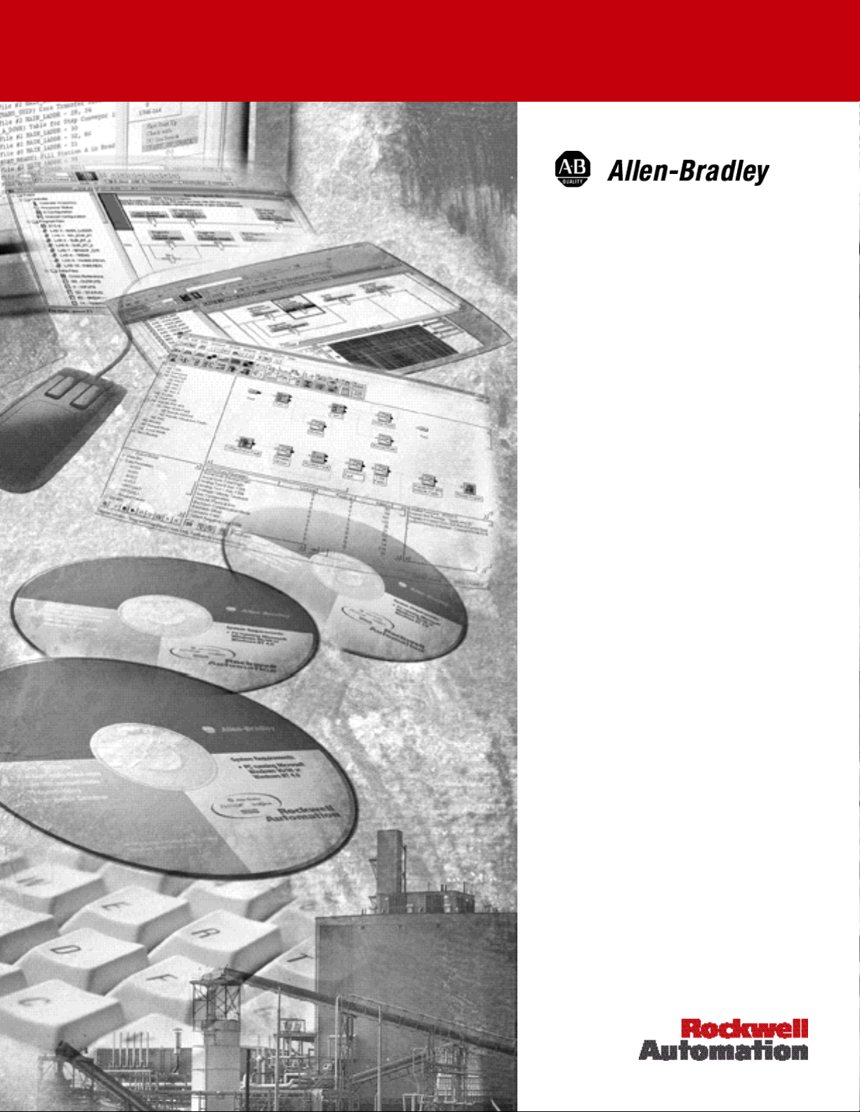
ULTRA Plus/IQ-2000/IQ-5000 System Components ........................................................... 5
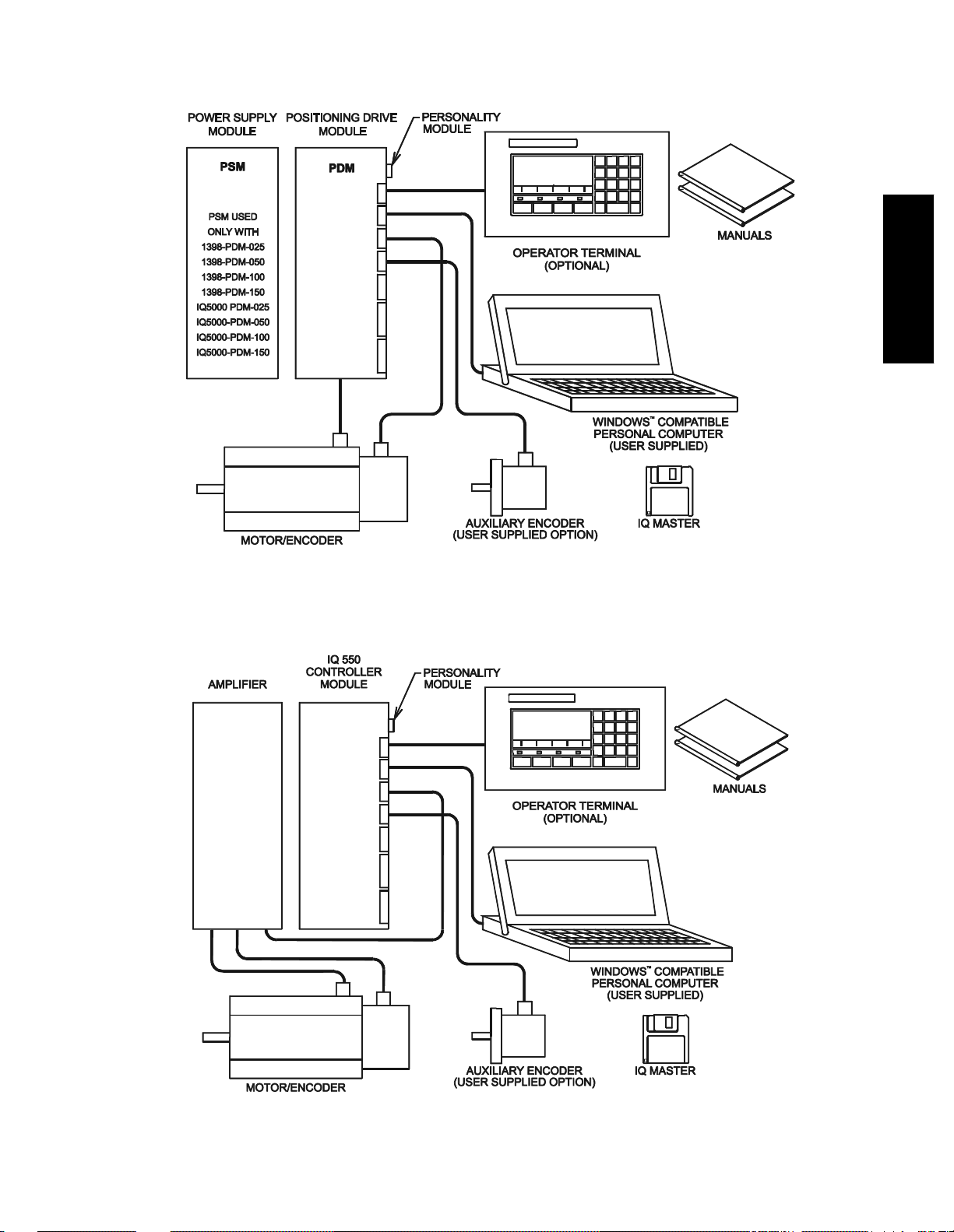
IQ-550 System Components ................................................................................................ 5
Personality Module Dialog Boxes ......................... ..... ......................................................... 33
ULTRA Plus/IQ-Series Block Diagram ............................................................................. 163
Legend Used in Home Diagrams ..................................................................................... 345
Normal Home Sequence Hitting Forward Limit Switch .................................................... 345
Normal Home Sequence Starting with th e Home Switch Active ...................................... 346
Normal Home Sequence, Hitting Home Switch while Moving Forward ............................346
Error: (-) Edge of Home Switch not Between Limits .........................................................346
Home Switch Active in the Opposite Sense ..................................................................... 347
Acceptable Deceleration Distance ...................................................................................347
Deceleration Distance Resulting in an Axis Crash ........................................................... 347
Publication 1398-PM601A-EN-P — October 2000
Page 16

xvi
Publication 1398-PM601A-EN-P — October 2000
Page 17

Preface
Introduction
Read this preface to familiarize yourself with this manual. This preface covers the following topics:
• Introduction
PREFACE
• Who Should Use this Manual
• Where to Find Help
• Contents of this Manual
• Related Documentation
• Conventions Used in this Manual
• Using Online Help
• Allen-Bradley Support
Who Should Use this Manual
Use this manual if you use IQ Master to configure and operate ULTRA Plus™ and IQ-Series® controllers, or
to design, test or run programs.
Where to Find Help
You can find help for IQ Master in both this manual, and Online Help.
1Publication 1398-PM601A-EN-P — October 2000
Page 18

P-2
PREFACE
Contents of this Manual
This manual contains the following sections:
Title Contents
Preface An overview of this manual and sources of information.
Getting Started Introduces the ULTRA Plus and IQ-Series controllers, and
the IQ Master software package.
IQ Master Environment Examines the menus and menu items in IQ Master.
Software and Hardware Integration Commissioning the ULTRA Plus and IQ-Series controllers
with IQ Master.
Programming A tutorial on programming motion with IQ Master and the
ULTRA Plus and IQ-Series controllers.
Language Reference Describes in detail each function, system variable and flag.
IQ Host Command Language Describes the host mode communications capabilities for
computers or PLCs to control the operation of an ULTRA
Plus and IQ-Series controller.
Appendixes Provides supplementary information and programming
examples for:
• DDE Server
• System Programs
• Optional Operator Terminal Function Key Programs
• Optional Home Programs
• Application Examples
• What’s New in Each Version
• Error Messages
Publication 1398-PM601A-EN-P — October 2000
Page 19

Related Documentation
The following documents contain additional information concerning related Rockwell Automation
products. To obtain a copy, contact your local Rockwell Automation office or distributor.
P-3
For information about: Read this document: Publication Number
Installing an ULTRA Plus
system.
Installing an IQ-550 system. IQ-550 Positi on Cont rol Module Instal-
Installing an IQ-2000 and IQ5000 system.
Programming electronic cams
for an ULTRA Plus or
IQ system.
The ULTRA Plus Positioning
Drive
ULTRA Series Specifications ULTRA Series Product Data 1398-2.0
Wire sizes and types for
grounding electrical equipment
ULTRA Plus Series Positioning Drive
Module Installat i on Ma nual
lation Manual
IQ-2000 and IQ-5000 Positioning
Drive Module Installation Manual
IQ-Series IQ-Cam Software Manual Part Number
ULTRA Plus brochure 1398-1.1
National Electrical Code Published by the
1398-5.1
Part Number
0013-1022-004
Part Number
0013-1027-004
0013-1053-001
National Fire Protection Association of
Boston, MA.
PREFACE
Allen-Bradley documentation, including ordering
instructions and alternative
media and multi-language
availability.
Allen-Bradley Publi cation Index SD499
Conventions Used in this Manual
The following conventions are used throughout this manual:
• Bulleted lists provide information, not procedural steps.
• Numbered lists provide sequential steps.
Publication 1398-PM601A-EN-P — October 2000
Page 20

P-4
PREFACE
Using Online Help
The following types of online help are available:
To use this: Do this: Description
Help Menu Either:
• Click on Help in the menu bar.
• Press ALT to activate the menu bar, then H to
pull down the Help menu.
• Press the F1 key.
Help Contents Either:
• Click on the Contents selection.
• Press the underlined letter (C in Contents).
• Use the arrow keys to highlight your selection
and then press ENTER.
How to Use
Help
Either:
• Click on the How to use Help selection.
• Press the underlined letter (H in How).
• Use the arrow keys to highlight your selection
and then press ENTER.
Displays the pull down
Help Menu.
Contains help on every
menu and menu item,
and the IQ Basic programming language.
Provides information
on how to use on-line
help.
Context
Sensitive Help
About IQ
Master
Either:
• Press Shift+F1,
• Click (the context sensitive help toolbar
button).
Then click anywhere in the IQ Master window,
such as a Toolbar button or menu item.
Either:
• Select About IQ Master from the Help menu.
• Click the toolbar button.
Provides he lp on a specific portion of IQ Master.
The mouse pointer will
change to an arrow and
question mark indicating Context Help mode.
The Help topic will be
shown for an item you
select.
Access the About IQ
Master section that displays: the version of IQ
Master that you are
using, the version of
Windows
using, and the amount
of memory available.
™
that you are
Publication 1398-PM601A-EN-P — October 2000
Page 21

Allen-Bradley Sup port
Allen-Bradley offers support services worldwide, with over 75 sales/support offices, 512 authorized
distributors and 260 authorized systems integrators located throughout the United States alone, plus
Allen-Bradley representatives in every major country in the world.
Local Product Support
Contact your local Allen-Bradley representative for:
• Sales and order support
• Product technical training
• W arranty support
• Support service agreements
Technical Product Assistance
If you need to contact Allen-Bradley for technical assistance, please review the information in this manual or in the Online Help file first. Then call your local Allen-Bradley representative. For the quickest
possible response, we recommend that you have the catalog numbers of your products available when
you call.
P-5
PREFACE
Publication 1398-PM601A-EN-P — October 2000
Page 22

P-6
PREFACE
Publication 1398-PM601A-EN-P — October 2000
Page 23

Part 1
Getting Started
This part of the manual introduces the Allen-Bradley ULTRA Plus and IQ-Series controllers and IQ
Master software. The requirements for the Persona l Computer (PC) to run IQ Master and the installation of IQ Master on your PC are covered.
INTRODUCTION
1Publication 1398-PM601A-EN-P — October 2000
Page 24

INTRODUCTION
Publication 1398-PM601A-EN-P — October 2000
Page 25

Introduction to IQ Master
About the Allen-Bradley IQ Master Manual
This manual contains the procedures you will need to work with IQ Master software. Throughout this manual, the terms ULTRA Plus, IQ, IQ-Series controller, and controller are used to refer to either an ULTRA
Plus, IQ-2000 or IQ-5000 Positioning Drive Module, or an IQ-550 Position Control Module unless otherwise specified. The term PDM is used to refer to either an ULTRA Plus, an IQ-200 0 o r an IQ-5 00 0 Pos itioning Drive Module unless otherwise specified.
The manual is organized into six parts plus appendixes. If you are using ULTRA Plus or IQ-Series equipment for the first time, you should read Parts 1 through 4 completely. Starting in Part 2, it is helpful if you
have an operational ULTRA Plus or IQ-Series controller at tached to you r PC . As y ou begin to develop your
programs you will begin using Part 5 as your reference guide. You only need to refer to Part 6 if you are
using a computer, PLC or some other device as a host.
INTRODUCTION
3Publication 1398-PM601A-EN-P — October 2000
Page 26

4 Introduction to IQ Master • ULTRA Plus or IQ-Series System Overview
INTRODUCTION
Part
Part 1 Getting Started
This part of the manual discusses the requirements for running IQ Master and covers the installation of IQ Master on your Personal Compu ter
(PC).
Part 2 IQ Master Environment
This part of the manual covers, in detail, each of the menu items in IQ
Master.
Part 3 Software and Hardware Integration
The interaction of IQ Master and the ULTRA Plus or IQ-Series controller is discussed in this part of the manual. You will learn how to configure your ULTRA Plus or IQ-Series controller for your application using
IQ Master.
Part 4 Programming
This part starts out with a tutorial on programming the ULTRA Plus or
IQ-Series which is designed to get you up and running quickly. From
there it moves into a detailed discussion of programming. The chapters
in this part are broken down into the major components of your program, for example: motion, math, etc.
Description
:
Part 5 Language Reference
The language reference part contains a detailed description of each
function, system variable and system flag, arranged in alphabetical
order.
Part 6 Host Language Commands
This part contains a detailed description of the host mode communication capability of the ULTRA Plus or IQ-Series controller. The host
mode is used if there is a host computer or PLC that will control operation of the ULTRA Plus or IQ-Series.
ULTRA Plus or IQ-Series System Overview
An ULTRA Plus or IQ-Series motion control system consists of a number of components connected to
accomplish a specific function. This section provides a brief overview of the various components of the
ULTRA Plus or IQ- Ser ies m otion control system.
Publication 1398-PM601A-EN-P — October 2000
Page 27
Introduction to IQ Master • ULTRA Plus or IQ-Series System Overview 5
INTRODUCTION
ULTRA Plus/IQ-2000/IQ-5000 System Components
IQ-550 System Components
Publication 1398-PM601A-EN-P — October 2000
Page 28

6 Introduction to IQ Master • ULTRA Plus or IQ-Series System Overview
INTRODUCTION
IQ Master
IQ Master is a Windows based software package that provides the user interface to the ULTRA Plus or
IQ-Series controller. It is used to edit and compile application programs, configure, monitor, and troubleshoot the controller.
IQ-550 Position Control Module
The IQ-550 Position Control Module is a stand alone single axis programmable position controller. It
can interface to most motor controllers through an analog command signal and encoder feedback to
form a system with power ranges from small subfractional horsepower DC systems to several hundred
horsepower vector drive induction motor systems. Motion programs are stored in on-board nonvolatile
memory. Two RS-232/RS-422 ser ial por ts provide communications with the per so nal computer and the
optional operator terminal. Optically isolated digital I/O simplifies machine interfaci ng and contro l.
Positioning Drive Modules (PDM)
The ULTRA Plus or IQ-Series Positioning Drive Module (PDM) is a self-contained single axis programmable motion controller. The PDM provides control and power for the brushless servo motor.
Motion programs are stored in on-board nonvolatile memory. Two RS-232/R S- 422 serial ports provide
communications with the personal computer and the optional operator terminal. Optically isolated digital I/O allows simple machine interfacing and control.
PDMs are manufactured in different packages which cover a wide range of power capability. The
ULTRA Plus PDM-10, 20, 30 and 75 and the IQ-2000 PDMs incorporate an integral power supply in
each PDM, and supply continuous torque’s of 3 to 90 inch-pounds in combinatio n with standar d motors.
The ULTRA Plus PDM-25, 50, 100 and 150 and the IQ-5000 PDMs use a separate power supply module, which can be shared among multiple PDMs, and provide continuous torque’s of 20 to 750 inch
pounds with standard motors.
PDMs with Integral Power Supply Modules
The ULTRA Plus (1398-PDM-10, 1398-PDM-20 and 1398-PDM-30) and the IQ2000 (PDM-10,
PDM-20, and PDM-30) are rated for 10, 20 and 30 amp peak currents respectively. These modules are
packaged with an integral power supply to achieve a small size.
Input power to the PDM-10’s, -20’s, or -30’s is single phase AC. Input power may be optionally isolated
trough a transformer. These PDMs have a built-in solid-state “soft charge” of the internal DC bus capacitor. They also include a built-in dissipative shunt regulator that provides quick discharge of the DC bus
capacitor, and double as an emergency synchronous motor dynamic brake. The PDM-30 allows use of
an optional external shunt resistor for applications requiring higher shunt power capability than what is
provided by t he internal shunt resistor.
PDMs with Separate Power Supply Modules
The ULTRA Plus (1398-PDM-25, 1398-PDM-50, 1398-PDM-100, and 1398-PDM-150) and the
IQ5000 (PDM-25, PDM-50, PDM-100, and PDM-150/150X) are rated for 25, 50, 100, and 150 amp
peak currents respectively. These higher power PDM modules use a separate power supply module
(PSM-50 or PSM-125), which may be shared among multiple PDMs to achieve the most economical
system package. Other than the packaging and power ranges, the higher power PDMs are identical to
the stand-alone PDMs from a setup and programming perspective.
Power Supply Module (PSM)
The power supply module is only required for ULTRA Plus (1398-PDM-25, 1398-PDM-50, 1398PDM-100, and 1398-PDM-150) and IQ-5000 systems. The Power Supply Module (PSM) can supply
DC power to as many as six PDM modules. The only inputs to the PSM are non-isolated or isolated
three phase power. The output is a two wire DC bus. The PSM requires no adjustments, protects itself,
provides troubleshooting diagnostics, and has a built-in so lid-state “soft charge” of the DC bus capacitors. It also includes a built-in dissipative shunt regulator that provides quick discharge of the DC bus
capacitors and doubles as an emergency synchronous motor dynamic brake.
Publication 1398-PM601A-EN-P — October 2000
Page 29
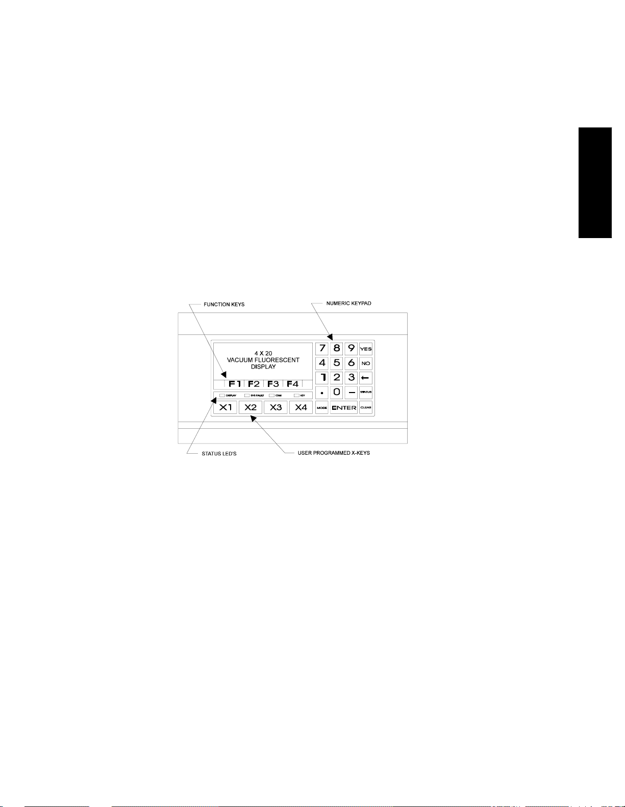
Introduction to IQ Master • ULTRA Plus or IQ-Series System Overview 7
Motors
A wide range of Allen-Bradley F-Series, H-Series, N-Series and W-Series permanent magnet synchronous motors are available for use with the PDM modules plus the I-6600 induction motor. Each motor
includes an integrally mounted encoder. Most motors are available with options including spring set
brake and/or shaft oil seal. The synchronous motors have a rear shaft available for mounting optional
feedback devices. MS style wiring connectors are standard for all S-Series and F-Series motors.
Operator Terminal
The optional Operator Terminal is a rugged man/machine interface device. It allows the machine operator convenient access to status information, program variables, and control functions, plus message display capabilities. The operator terminal has a bright 4 line by 20 character vacuum fluorescent display
and a sealed membrane keyboard with tactile feedback.
The operator terminal displays multiple status screens for monitoring and diagnostics. Four soft function keys are available to perform up to twenty-four (24) predefined functions, which include selecting
and running a program, jogging the system, stopping a program, and more. The user program may display messages and prompts on the screen, and receive input from the operator terminal keypad to enter
program variables such as distances, speeds, batch counts, and others. Four additional user programmable keys provide extra flexibility within a user program.
INTRODUCTION
Personality Module (PM)
The Personality Module is a nonvolatile memory device which stores the information necessary to customize an ULTRA Plus or IQ-Series controller for a specific application. The PM holds parameters to
match the motor and the controller, as well as user programs and parameters. A Personality Module may
be physically removed and transferred to another ULTRA Plus or IQ-Series controller if the replacement of a controller is necessary to simplify servicing the machine. The Personality Module data can
also be saved in a computer file and loaded into the ULTRA Plus or IQ using the File, Transfer, dialog
box.
Manuals
The manuals are conveniently broken into two volumes. The appropriate ULTRA Plus or IQ-Series
Installation Manual (1398-5.1, Part Number 0013-1027-004 or Part Number 0013-1022-004) contains
all the information required for mounting and wiring the system. This manual contains all the information that a user and programmer require to quickly set up, and develop programs for the controller.
Option Cards
Each ULTRA Plus or IQ-Series controller can have an option card (not pictured) mounted on its main
circuit board, inside the cover. The controller has a connector which connects the option card to the
power supplies and microprocessor through a ribbo n cable. Th e option cards curren tly availab le include
a Memory and I/O Expansion Card and an I/O Expansion Card.
Publication 1398-PM601A-EN-P — October 2000
Page 30

8 Introduction to IQ Master • Symbols and Conventions
INTRODUCTION
Memory and I/O Expansion Card
Additional memory and I/O may be added with a Memory and I/O Expansion Car d. This board adds the
following memory, input and output capabilities to the ULTRA Plus or IQ-Series controller.
• 32 Kbytes of additional nonvolatile memory for the storage of up to 32 additional programs.
• 32 TTL Inputs.
• 16 TTL Outputs.
• 4 twelve bit A nalog Input s.
I/O Expansion Card
Additional I/O may be added with an I/O Expansion Card. This board adds the follow ing input and output capabilities.
• 32 TTL Inputs.
• 16 TTL Outputs.
Personal Computer (PC)
A user supplied Personal Computer is required to run I Q Master software, and its requirements are sp ecified in “Minimum Personal Computer Requirements” on page 9.
Symbols and Conventions
This manual uses the following typographic conventions:
Example: Description:
DIF dist,condition,JUMP
label
Gn, Vn, Fn, Bn User variables. The capital letters (G, V, F, B) can be typed as
MOVD = value [,V = value] Square brackets indicate an optional item. If the optional
IQ Basic instructions are shown in all capital letters.
Capital letters indicate IQ Basic keywords, which are required
parts of IQ Basic statements. Keywords include language commands (e.g. DIF), local parameters (e.g. KP), dedicated flags
(e.g. ATHOME) and variables (e.g. G1). In this manual keywords are shown in all capital letters. However, IQ Basic is a
case insensitive language and can be typed in lower, upper, or
mixed case. A keyword must be followed by a s pace bef ore any
other part of the instruction.
Small italic letters indicate user supplied values. You must substitute a value according to rules explained in the text. This can
be a variable or a constant.
either lower case or upper case. The small italic letter in each
name represents the number of any register. For example G13
might be a substitute for Gn.
parameters are not included, then the current setting for that
parameter is used.
ACCEL = value
G1 = VEL
Fn = ATHOME
CLRPEAKS = ON
Publication 1398-PM601A-EN-P — October 2000
Set a system variable.
Read a system variable.
Read a flag variable.
Set a flag variable.
Page 31

Introduction to IQ Master • Minimum Personal Computer Requirements 9
MOVD = G1, V = G2 Example programs or program fragments are shown in this
font.
win Text presented in lower case bold is information to type at the
DOS prompt. For example: To start Windows from the DOS
prompt, type win and then press ENTER.
ALT+F4 Keys that should be pressed simultaneously are shown with a
(+) betwee n the key names.
ALT, F, N Keys that should be pressed in sequence are shown with a (,)
between the key names. This example would open the File
menu and then open a new file.
Minimum Personal Computer Requirements
IQ Master
• A DOS system computer with a 286 microprocessor or better (386 or 486 preferred)
• A hard disk, with 1.5M B free
• 3½ inch, 1.44MB floppy disk drive
INTRODUCTION
• 2MB of RAM minimum (4 MB recomme nded)
• An Enhanced Graphics Adapter (EGA) or better resolution monitor
• Microsoft
In addition, a mouse is recommended, but not required.
Windows version 3.1 or later
Publication 1398-PM601A-EN-P — October 2000
Page 32

10 Introduction to IQ Master • New Features
New Features
INTRODUCTION
There have been many additions and enhancements to the ULTRA Plus or IQ systems. A detailed
description of these new features and command changes is in the appendix “What’s New in Each Ver-
sion” on page 410. If you have used the ULTRA Plus or IQ system before, reading this appendix is recommended. The following is a brief list of the new features:
New in Version 3.2.4 vs. Version 3.2.3
• IQ Master software runs on Allen-Bradley ULTRA Plus.
New in Version 3.2 vs. Version 3.0
• Extended Debug features
• Software programmable Personality Module
• Print and Read statements precision to 4 decimal points.
• Looping and Repeat value range from 0 to 65535.
• Drive current values scaled using drive module (Dm) current.
• Purge Motion function added.
• DP1 and DP2 encoder position statements added.
New in Version 3.0 vs. Version 2.1x
• Support for IQ CAM
• Tracking function enhancement to electronic gearing
• Compiler options program statements
• Off-line parameter editing
• DDE server capability
• Support for redefining key codes for generic operator terminals
• Movecomplete and Jogactive system flags
• Support for connecting one Operator Terminals to multiple IQs
• Toolbar button for File Transfer
New in Version 2.1 vs. Version 2.0
• Support for the IQ-550 Position Control Module
• Support for a generic operator terminal
• Default File Extension changes - all IQ files begin with “Q”
• T oo l bar but ton s
• Context Sensitive Help
• Replace function added to the editor
• Ability to monitor G and V variables
• Ability to directly save a file to the IQ after successful compile
New in Version 2.x vs. Version 1.x
• Windows based environment
• On line help
Publication 1398-PM601A-EN-P — October 2000
Page 33

Introduction to IQ Master • New Features 11
• Complete Host Language Command set
• Off line compiler and full screen editor
• IQ Basic language enhancements:
– Multiple statements can be treated as a group.
– T wo new statements have been added to repeatedly execute a statement or group of statements
based on a condition: the While and the Do While statements.
– Parentheses can be used around a condition for clarification or to establish operator prece-
dence.
– Two new variables have been added to capture position information based on an index pulse:
IX1P2 (POS2 on index 1) and IX2P1 (POS1 on index 2).
INTRODUCTION
Publication 1398-PM601A-EN-P — October 2000
Page 34

12 Quick Start Check List • Introduction
INTRODUCTION
Quick Start Check List
Introduction
New users of ULTRA Plus or IQ-Series controllers are encouraged to read through the appropriate
ULTRA Plus or IQ-Series Installation Manual (1398-5.1, Part Number 0013-1027-004 or Part Number
0013-1022-004) and this manual before beginning a project. However, for experienced users of the
ULTRA Plus or IQ-Ser ies, this check list was developed to guide you through the process of getting
your system up and running. If you are a new user you will want to return to this section after you have
completed your review of the rest of the material.
Quick Start Check List
The following check list will step you through the items that are required for the typical application:
1. Install IQ Master on your PC. See “Using the IQ Master Setup Program” on page 17.
2. Install the ULTRA Plus or IQ-Series controller and go through the Start-up procedure. See
“Applying Power for the First Time” on page 21.
3. Connect the serial cable between the PC and the ULTRA Plus or IQ-Series controller.
4. Verify that the ULTRA Plus or IQ-Series Controller and PC can communicate properly
over the serial cable connected between plug 6 (P6) on the controller and a serial communications port on the PC.
• Go to the Diagnosti cs menu and select Version (page 72). If a dialog box wi th t h e v er-
sion is displayed, communication is working properly and you may skip to step 5. If
an error message is displayed, continue with step 4.
Publication 1398-PM601A-EN-P — October 2000
Page 35

Quick Start Check List • Quick Start Check List 13
• If you get an “IQ not responding” error message, go to the Communications menu,
PC Set Up and check your communications setup. You should first verify that the
communications port you have selected is the one that your cable is connected to.
Then verify that the communications protocol matches the protocol in the ULTR A
Plus or IQ-Series controller. The factory settings for a new controller are:
– RS-232
– 9600 Baud
– No Parity
– 8 Data bits
– 1 Stop Bit
– Flow Control XON/XOFF
If this is not a new controller any of these setting may have been changed by the previous user.
• If you have selected an address on the address DIP switches, verify that the same
address is selected in the Communications menu, Axis Select dialog box.
• Verify that the serial cable is constructed properly
Controller
Connector
RXD- P6-2
TXD- P6-3
Com P6-5
Shield P6-6
PC 9-pin
Serial
Connector
2 RXD
3 TXD
5 GND
• Verify that your system has the serial communication port that you have selected.
With W indows, y ou received the Diagno stic program, MSD.EXE. Exit IQ Master an d
Windows and type msd at the DOS prompt. Select the Com Ports button. Verify that
there is a port address for the serial port that you have selected. Return to Windows
and IQ Master.
• If you still have not been able to communicate with the co ntroller see “Allen-Bradley
Support” on page 5.
INTRODUCTION
5. Go to the Parameter menu and select System. Make your selections and choose OK.
6. Go to the Parameter menu and select Velocity/Accel. Make your selections and
choose OK.
7. Go to the Parameter menu and select Inputs. Make your selections and choose OK.
8. Go to the Parameter menu and select Outputs. Make your selections and choose OK.
9. Go to the Parameter menu and select Default Outputs. Make your selections and choose
OK.
10. Go to the Parameter menu and select Feedback Configuration. Make your selections and
choose OK.
11. Go to the Parameter menu and select Fkey Set Up. Make your selections and choose OK.
Publication 1398-PM601A-EN-P — October 2000
Page 36

14 Quick Start Check List • Quick Start Check List
INTRODUCTION
12. Go to the Run menu, Tune. Follow the Auto Tuning procedure outlined in Part 2 of this
manual. If required, perform the manual tuning procedure.
13. If you have programs that were created for version 1, refer to Appendix C to convert the
programs to be compatible with version 2. Then continue at the beginning of Part 4 with a
Programming Tutorial Introduction
Publication 1398-PM601A-EN-P — October 2000
Page 37

Getting Started with IQ Master • Hardware and Software Requirements 15
Getting Started with IQ Master
INTRODUCTION
Hardware and Software Requirements
At this point you should have Windows installed on your PC if you are going to use IQ Master. If not,
refer to the appropriate Microsoft manuals to install Windows on your computer.
T o run a program, and/or access many of the IQ Master setup and configuration windows you will need
to have the ULTRA Plus or IQ-Series controller installed and ready to apply power. The procedure for
installing the hardware is in the appropriate ULTRA Plus or IQ-Series Installation Manual (1398-5.1,
Part Number 0013-1027-004 or Part Number 0013-1022-004).
Using Windows Without a Mouse - A Quick Review
IQ Master can be used without a mouse if you use the standard key combinations to activate menus,
select radio buttons, move between windows, etc. Some of the most commonly used key combinations
are summarized in the following two tables.
Windows Hot Keys
Name Description
F1 Help
ALT+F4 Exit the application that you are currently in, or exit Windows if you
are in the Program Manager.
ALT+HYPHEN Activate the Control-menu box in a document window, for example,
when editing a file.
Publication 1398-PM601A-EN-P — October 2000
Page 38

16 Getting Started with IQ Master • Using Windows Without a Mouse - A Quick Review
INTRODUCTION
ALT+F6 Switch between the main application and one child window (for
example, to switch between the IQ Master for Windows main menu
and the Run Control dial og b ox) ; o r, to switch between multiple child
windows (for example, to switch between the Status and Run Control
dialog boxes).
ALT+SPACEBAR
1
Activate the C ontrol-menu bo x of the act ive window (the box with t he
hyphen in the upper left corner of the window). F10, ENTER can also
be used to activate the Control-menu box. Use this menu to restore,
move, maximize, minimize, or close the window. (For document windows use ALT, HYPHEN to activate the C ontrol-men u box , f or exam-
ple, when editing a file.)
ALT+TAB Switch between active tasks.
CTRL+F6 Switch between multiple document windows (for example, to switch
between multiple files that you are editing).
SHIFT+ALT+F6 Alternate switching between the main application and multiple child
windows (for example, to switch between the IQ Master for Windows
main menu and the Run Control dialog bo x and then swi tch to the S ta-
tus dialog box).
SHIFT+TAB Move to the previous item in a dialog box.
TAB Move to the next item in a dialog box.
1. Using Restore from the Control menu when a window is maximized has the same result as clicking the Restore button (the up and down ar row in th e up per r ight cor ner o f a wind ow). I f the ap plication has been reduced to an icon, Restore will return the window to its previous size.
Publication 1398-PM601A-EN-P — October 2000
Page 39

IQ Master Hot Keys
Name Description
F2 Compile the program in the active window.
F7 Save the program in the active window to the ULTRA Plus or IQ.
CTRL+S Save file in the active window to disk
ALT+Back Space Restore the most recently deleted text
SHIFT+Delete Cut the current text selection from your program into the clip-
CTRL+Insert Copy the selected text into the clipboard
Getting Started with IQ Master • Using the IQ Master Setup Program 17
board
SHIFT+Insert Paste the contents of the clipboard into the program at the cursor
location
F3 Find Next - repeat the last find, looking in the forward direction
F4 Find Previous - repeat the last find, looking in the reverse direc-
tion
F8 Display the Run Control dialog box
CTRL+X Stop motion
F9 Display the Status dialog box
Using the IQ Master Setup Program
To install IQ Master to the hard drive:
1. Make a backup copy of your disks before proceeding. If your computer has only one floppy disk
drive, type diskcopy a: b: from the DOS command line prompt. Otherwise, copy disk from the
disk menu in the Windows file manager. You will be prompted when to insert the SOURCE disk
and when to insert the TARGET disk. As an alternative, copy the disk to your hard disk and then
from the hard disk to another floppy disk.
2. If Windows is not already running, type win at the DOS prompt.
-orIf Windows is running, close any open applications.
3. Insert the IQ Master disk in to a 1.44MB floppy disk drive, typically drive a:, and close the drive
door.
4. From the File menu, choose Run (ALT, F, R).
5. Type a:setup and then press ENTER. A dialog box will appear saying that the setup is initializing
(this box may be present for 40 seconds).
6. A dialog box will appear, confirming that you are about to install IQ Master on to your hard drive.
Choose Cont inue, or pres s ENTER.
7. Next, the Setup Options dial og bo x w il l appear. This box lists the dif fer ent com pon ent s whic h m ay
be installed. If you do not wish to install these files, clear the check boxes and choose Continue.
8. Setup will then ask where you would like to install IQ Master.
To accept the path that Setup proposes, choose Continue.
-orT o choose your o wn directory, type a new path in the Install To box, and then choose Continue. You
will not have the opportunity to confirm your entry so type carefully.
9. A status bar will be displayed to keep you informed of the installation p rogress. When Setup is
complete, choose OK or press ENTER to return to Windows.
INTRODUCTION
Publication 1398-PM601A-EN-P — October 2000
Page 40

18 Getting Started with IQ Master • The Readme File
The Readme File
INTRODUCTION
When Setup installed IQ Master, a file, README.WRI was installed in the IQ Master dir ectory. This
file contains information that became available after this manual was printed. A Read Me Icon was
added to the IQ Master group. After you install IQ Master you can access this file by double clicking o n
the Read Me Icon.
Publication 1398-PM601A-EN-P — October 2000
Page 41

Getting Started with IQ Master • Starting and Quitting IQ Master 19
Starting and Quitting IQ Master
Setup automatically creates the IQ Master program group, the IQ Master icon and then returns you to
Windows.
IQ Master group
IQ Personality Module
Generator icon
Read Me iconIQ Master icon
To Start IQ Master
You can start IQ Master by using either the mouse or the keyboard.
• Double-click the IQ Master icon.
-orSelect the IQ Master icon using the arrow keys, and press ENTER.
Tip: If the IQ Master group is not active, hold down CTRL and press TAB until the IQ Master title
bar and icon are highlighted, or use the Window menu.
IQ Master may also be started as a DDE Server, refer to “DDE Server” on page 323.
The IQ Master Screen
When you start IQ Master a blank screen with the IQ Master title bar, menus, and toolbar appears. A
typical screen with a program being edited is shown below.
The title bar shows the name of the
program being edited. A * indicates
the program has not been saved.
Menus on the
menu bar
provide access
Tool bar buttons provide
quick access to commands.
to IQ Master
commands.
INTRODUCTION
Edit window contains
file being edited.
The cursor indicates where
text will be inserted.
Scroll bars display different
parts of a program.
Messages are displayed
in the status bar.
This shows
the line
number the
cursor is on.
Quitting IQ Master
When you quit IQ Master, if you have made changes to your program, IQ Master will ask if you want to
save the changes. If you answer yes and you have not named the program, IQ Master will save it under
Publication 1398-PM601A-EN-P — October 2000
Page 42

20 Getting Started with IQ Master • On-line Help
the name that it used to open it with, FILEn, ⇒with a QPS extension. IQ Master assigns a number n to
each new file that is open to distinguish it from other unnamed files.
To Quit IQ Master, from the File menu, choose Exit (ALT, F, X) or pres s ALT+F4.
• If you are using a mouse, point to the File menu and click the left mouse button. Then point to the
Exit command and click the left mouse button again.
INTRODUCTION
On-line Help
• If you are using the keyboard, press the ALT key to activate the menu bar, press the F to choose the
File menu, and then press X, the underlined letter in the Exit command, or press ALT+F4.
There is extensive help in IQ Master on the commands and procedures you use to accomplish tasks. In
addition, there is information on all the language statements, system variables, and system flags.
To Start Help:
Help Menu
1. If you are using a mouse, point to the Help menu and click the left mouse button.
-orIf you are using the keyboard , press the ALT key to activate the menu bar and press H to choose the
Help menu.
2. From the Help menu, choose Contents to get help on IQ Master
-or choose How to Use Help to get help on moving around in Help.
F1 Key
Highlight the item you need information on and press the F1 key.
Toolbar
Click on the context sensitive Help button, , then click the item you want help on.
Pressing Shift+F1 has the same effect as clicking on the context sensitive Help button.
Upgrading from Version 1
If you are currently using a version 1 IQ, you will need to upgrade the system programs in your personality module and make some minor changes to your programs. A detailed procedure for upgrading is in
Appendix D, Upgrading From Version 1.
Publication 1398-PM601A-EN-P — October 2000
Page 43

Applying Power for the First Time • Start-Up Procedure for ULTRA Plus and IQ-2000 Systems 21
Applying Power for the First Time
INTRODUCTION
Outlined below are the steps that should be followed when applying power to the equipment for the first
time. This procedure covers
Controllers, Motors and the Operator Terminal.
This start-up procedures assumes that the equipment has previously been mounted and wired, but has
not had power applied to it.
ULTRA Plus, IQ-2000 PDMs, IQ-5000 PDMs, IQ-5000 PSM, IQ-550
Start-Up Procedure for ULTRA Plus and IQ-2000 Systems
1. Measure voltage between terminals marked L1 and L2 to ensure incoming power is off. Also mea-
sure voltage between terminals marked L1 AUX and L2 AUX if used, to ensure power is off. The
green READY LED (power supply) and the bi-color status LED should be off.
2. Disconnect input wires connected to terminals L1 and L2 (also terminals L1 AUX and L2 AUX if
used). Arrange the wires in a safe position to test the incoming voltage.
3. Turn input power on and measure line voltage to ensur e that it is in the proper voltage range (1 15 or
230 VAC depending on motor speed requirements).
4. Turn power off and reconnect the wires to terminals L1 and L2 (and terminals L1 AUX and L2
AUX if used).
5. With input power still off, disconnect motor leads from terminals R, S, and T. Verify with an ohm-
meter that the resistance between terminals R to GND, S to GND, and T to GND is above 500k
ohms. If the resistance is OK, reconnect the motor leads to the terminals marked R, S, and T.
6. Make sure that the Personality Module (PM) is properly configured. If necessary, refer to the
Applying Power chapter in the appropriate ULTRA Plus or IQ-Series Installation Manual (1398-
5.1, Part Number 0013-1027-004 or Part Number 0013-1022-004) for step-by-step instructions on
configuring a Personality Module using IQ Master software.
7. Connect all interface cables (P1-P7) to the PDM.
Publication 1398-PM601A-EN-P — October 2000
Page 44

22 Applying Power for the First Time • Start-Up Procedure for ULTRA Plus and IQ-5000 Systems
ATTENTION
!
INTRODUCTION
Start-Up Procedure for ULTRA Plus and IQ-5000 Systems
8. Make sure that the motor is not connected to the load when app lyi ng power to p reven t any mechan ical damage in case of a fault. Apply input power with th e PDM disab led and check the LEDs. The
green READY LED should turn on and the bi-color status LED should turn green. If the status
LED is red rather than green, the PDM is in a fault condition. Se lect Status from the Monitor menu
to find out the type of fault. Correct the fault (the status LED will turn green when the fault has
been cleared and a hard reset performed). Check that air is coming out of the top of the PDM near
the mounting plate to ensure that the fan is operating.
9. Select Encoder from the Diagnostics menu. Verify that Counts increases positively when the motor
shaft is rotated clockwise as viewed facing the motor shaft.
10. Remove input power. The LEDs should turn off within one second.
Starting an ULTRA Plus or IQ-5000 involves starting a Power Supply Module (PSM) and at least one
Positioning Drive Module (PDM). The PSM is checked first and then the PDMs. Perform the start-up
procedure on all the PDM attached to the PSM at the same time.
Dangerous voltages may exist after power is removed! Check the DC
bus voltage after removing power and before working on an ULTRA
Plus or IQ-5000 power supply module or ULTRA Plus or IQ-5000
positioning drive module.
Power Supply Module
1. Measure voltages at L1, L2, and L3 phase to phase to ensure incoming power is of f. Make sure that
the green PSM READY LED is off. Remove the PSM cover.
2. Disconnect all three phase input wires attached to L1, L2, and L3. Arrange the inpu t wires in a safe
position to test incoming voltage levels.
3. Turn input power on and measure phase to phase voltages to ensure that they are balanced and in
the proper voltage range (88-265 VA C 3 phase).
4. Turn power off and reconnect the wires to L1, L2, and L3. Phasing is arbitrary.
5. Disconnect all wires from the PSM DC bus terminal posts marked + and -. Install the PSM cover,
then turn on input power. Verify that DC bus voltage is in the proper range (125-375 VDC, 325
VDC with 230 VAC input). Check that the green PSM READY LED is on and that all three red
LEDs are off and that the PSM fans are operating.
6. Disconnect input power and check that the green LED goes o ff and the DC bus voltage falls to less
than 15 VDC within one second. If so, then the PSM is working properly.
7. Remove PSM cover. Reconnect the DC bus wires to the PSM terminals marked + and - insuring
that proper polarity is maintained. Install the PSM cover.
Note: Do not substitute the DC bus wires provided with wires of a different length or gauge as a failure
may occur.
Start-Up Procedure for ULTRA Plus or IQ-5000
1. Measure voltage at terminals marked L1, L2, and L3 to ensure incoming power is off.
2. Disconnect all interface cables (P1-P7) from each PDM and remove all covers. Disconnect all
motor leads from the terminals marked R, S, and T. Verify with an ohmmeter that the resistance
between terminals R to GND, S to GND, and T to GND is above 500k ohms. If the resistance is
OK, reconnect the motor leads to the terminals marked R, S, and T. V er ify that the DC bus wires are
connected to the PDM with the correct polarity.
Publication 1398-PM601A-EN-P — October 2000
Page 45

3. Make sure that each PDM has the Personality Module (PM) properly configured. If necessary, refer
ATTENTION
!
to the Applying Power chapter in the appropriate ULTRA Plus or IQ-Series Installation Manual
(1398-5.1, Part Number 0013-1027-004 or Part Number 0013-1022-004) for step-by-step instructions on configuring a Personality Module using IQ Master software.
4. Install all covers. Connect all interface cables (P1-P7) to the PDMs.
5. Make sure that the motor is not connected to the load when app lyi ng power to p reven t any mechan -
ical damage in case of a fault. Apply input power with all PDMs disabled and check the bi-color
status LED on the PDM. The LED should turn green . I f the statu s LED is red rather than gr een, th e
PDM is in a fault condition. Select Status from the Monitor menu to find out the type of fault. Correct the fault (the status LED will turn green when the fault has been cleared and a hard reset performed). Check that the fans are operating. The green PSM READY LED should turn on and
remain on.
6. Select Encoder from the Diagnostics menu. Verify that Counts increases positively when the motor
shaft is rotated clockwise as viewed facing the motor shaft.
7. Remove input power. The PDM and PSM LEDs should turn off within one second. Measure DC
bus to ensure voltage is below 15 VDC.
Motor Start-Up Procedure
Applying Power for the First Time • Motor Start-Up Procedure 23
INTRODUCTION
This motor start-up procedure is for ULTR A Plus or IQ-2000 and IQ-5000 systems only.
Motors can cause extensive damage and injury if mounted improperly.
1. The motor(s) should be disconnected from the mechanical load(s) when initially checking out the
system. If this is not possible, take adequate precautions in case of a fault.
2. Disconnect all interface cables from the PDM and remove the cover. Connect the 4 motor wires (R,
S, T , and ground ) to the proper PDM. In stall all covers and co nnect all interface cables to the PDM.
With each PDM disabled, re-apply input power and check for proper power-up diagnostics as
shown by the status LED on each unit.
3. Select Gains/Limits from the Parameter menu. Set Ilimit to a low value (25% of peak current is a
typical value). Select Velocity/Acceleration from the Parameter menu and set the Jog Velocity to a
relatively low speed, such as 50 RPM. Enable each PDM and make sure there is no shaft motion.
Activate the Jog forward input and check for clockwise rotation of each motor shaft as viewed facing the motor shaft. If motor does not turn clockwise, then check that motor power wires and
encoder wires are connected properly.
4. Disable all PDMs and turn off input power. Measure the DC bus voltage to be sure that it is below
15 VDC.
5. Now that the system installation is verified, return the Ili mi t para m e ter to a value to suit the appli-
cation.
Publication 1398-PM601A-EN-P — October 2000
Page 46

24 Applying Power for the First Time • Start-Up Procedure for IQ-550 Systems
ATTENTION
!
ATTENTION
!
Start-Up Procedure for IQ-550 Systems
INTRODUCTION
1. Measure voltage between IQ-550 terminals marked L1 and L2 to ensure incoming power is off.
The bi-color status LED should be off.
2. Disconnect input wires connected to terminals L1 and L2. Arrange the wires in a safe position to
test the incoming voltage.
3. Turn input power on and measure line voltage to ensure that it is in the proper voltage range (115/
230 VAC).
4. Turn power off and reconnect the wires to terminals L1 and L2.
5. Connect all interface cables (P1-P7) to the IQ-550.
6. Turn power on.
7. Make sure that the IQ-550 has the Person ality Module (P M) properly configured. If necessary, refer
to the Applying Power chapter in the appropriate U LTRA Plus or IQ-Series Installation Man ual
(1398-5.1, Part Number 0013-1027-004 or Part Number 0013-1022-004) for step-by-step instructions on configuring a Personality Module using IQ Master software.
Before proceeding from this point, it is important to understand that the ULTRA Plus/IQ2000/IQ5000
needs to receive positive counts from its connected system when delivering a positive current command
to that system. It is assumed that the amplifier and motor have already been tested to determine direction of rotation for a positive current command input. Consult your drive/amplifier hardware manual to
determine the appropriate procedure for establishing the relationship between the polarity o f the current
command and the direction of the rotation of the motor.
Failure to determine the proper relationship between current
command and encoder feedback can result in a runaway condition
which may cause damage to equipment and/or personal injury.
8. Ensure the motor is not connected to the load when applying power. This prevents any mechanical
damage in case of a fault. Apply input power with the ULTRA Plus/IQ2000/IQ5000 disabled and
check the I-color Status LED.
• Verify the status LED is green.
• If the status LED is red, the ULTRA Plus/IQ2 000/IQ5000 is in a fault condition. Select Status
from the Monitor menu to find out the type of fault. Correct the fault (the status LED will turn
green when the fault has been cleared and a hard reset performed).
9. Select Encoder from the Diagnostics menu.
• Verify that the Counts value increases positively when the motor shaft is rotated in the direc-
tion (clockwise or counterclockwise) established as the positive current command.
• If the Counts value decreases, switch A+ and A- on connector P5 (or B+ and B-).
Changing the rotation parameter in the Parameter menu, system dialog
box of IQ Master will not adjust for polarity mismatches in the current
command signal and the encoder feedback.
Publication 1398-PM601A-EN-P — October 2000
Page 47

10. Enable the ULTRA Plus/IQ2000/IQ5000 using the Enable input or Enable from the Run menu of
IQ Master. Verify the motor is stationary and has holding torque.
11. Command motion using the Jog inputs or the Run Control dialog box of IQ Master. Verify the
motor rotates in the proper direction.
12. Remove input power. The LED should turn off within one second.
Operator Terminal
The Operator Terminal requires no special start-up procedure. Simply apply power to the operator terminal as described in the appropriate ULTRA Plus or IQ-Series Installation Manual (1398-5.1, Part
Number 0013-1027-004 o r Part Number 00 13-1022-0 04). The opera tor termin al should sound a tone on
power-up and the display LED should be lit. No message will appear on the screen unless the operator
terminal is connected to the ULTRA Plus or IQ serial port and the ULTRA Plus/IQ sends a message to
the operator terminal.
Backup Personality Module
After correctly setting up the system, back up the contents of the Personality Module (NVRAM) to a
file on your PC, using File Transfer. Refer to Part 2 • IQ Master Environment, File menu, Transfer for
details.
Applying Power for the First Time • Operator Terminal 25
INTRODUCTION
Publication 1398-PM601A-EN-P — October 2000
Page 48

26 Applying Power for the First Time • Backup Personality Module
INTRODUCTION
Publication 1398-PM601A-EN-P — October 2000
Page 49

Part 2
IQ Master
MENUS
Environment
In this part of the manual, each menu and menu item is examined. The figures with menus and dialog boxes depict images from IQ Master.
27Publication 1398-PM601A-EN-P — October 2000
Page 50

MENUS
Publication 1398-PM601A-EN-P — October 2000
Page 51

File Menu
MENUS
The File menu provides all the functions to load (open) and save files to both the PC and the ULTRA Plus or
IQ-Series controller. Along with these file commands, the menu contains the Print, Transfer, Initialize (program) Personality Module, and Exit functions.
To Access File Menu Items
• Select the File menu by clicking on File in the menu bar,
-orpress ALT to activate the menu bar, then F to pull down the File menu.
• Select the menu item by clicking on your selection,
-orpressing the letter that is underlined in your selection (for example the “S” in Save),
-orusing the arrow keys to highlight your selection and then press ENTER.
29Publication 1398-PM601A-EN-P — October 2000
Page 52

MENUS
30 File Menu • PC Disk Commands
PC Disk Commands
New
Select New from the File menu or click the toolbar button to open (create) a new file on the PC.
The default file name will be FILE1.QPS, the next one FILE2.QPS, and so on. After editing the program, use Save As to save the file to disk under a name you choose.
To save the program to the ULTRA Plus or IQ, use Save Program to IQ (compile the program first if
you want to save the executable as well as the source).
Open
Select Open from the File menu or click the toolbar button to open an existing file on the PC.
Select the file to be opened from the Open file dialog box.
Save
Select Save from the File menu or click t he toolbar button to save t he curr ent file as it i s named on
the PC.
Save As
Select Save As from the File menu to save the current f ile under a dif ferent nam e on the PC. This can b e
used to rename your program or to copy your program.
IQ Commands
Open IQ Program
Select Open IQ Program from the File menu to open an existing source file in the ULTRA Plus or
IQ-Series controller . Select the file to be open ed from the IQ Directory dialog bo x. The file to be opened
must be a source file–executable files cannot be edited.
The IQ Directory dialog box shows current programs that exist in the ULTRA Plus or IQ. The title of
the program is shown in the Program List box if the file has been compiled with a Title statement. Select
the program from the Program List box or, if you know the program number, enter the number in the
Program Number box.
The Directory drop down list box is used to change from Program Directory to System Directory. The
Program Directory contains user programs; the System Directory contains System Programs–programs
such as Jog, Home, Start, Stop, etc., that are used as predefined functions. The Auto Program is also in
the System Directory (program #0). The System Program s can be run by ass igning an Fk ey on the Operator T er minal to the progr am (use Fkey Set Up), or by a predefined input in specific cas es such as Home
or Emergency Return.
After opening an existing source file, if you want to save the file to disk on the PC, use Save As and
specify the file name.
Save Program to IQ (F7)
Select Save Program to IQ from the File menu, click the toolbar button, or press F7 to save the
current file to the ULTRA Plus or IQ. Then select the program number to store the file in the IQ Directory dialog box. Choose the Executable radio button to save only the executable pro gram (if the file has
been compiled with no errors). T o save both the source and execu table programs, choose the Sou rce and
Executable radio button. (If the program has not been compiled successfully, only the source will be
saved.)
Publication 1398-PM601A-EN-P — October 2000
Page 53

Delete IQ P rogram
Select Delete IQ Program from the File menu to delete a file in the ULTRA Plus or IQ. Select the type
of program to be deleted–either just the source or both source and executable by selecting the appropriate radio button. Then select the program to be deleted from the IQ Directory dialog box.
File Extensions
IQ Master uses default file extensions for specific types of files, however, any file may be saved with
any extension desired. All default file extensions begin with the letter Q to indicate a file used with
ULTRA Plus or IQ-Series products and IQ Master. The default file extensions and a description of each
is listed below.
QPS IQ Program Source file. Files with a QPS extension should be IQ programs in ASCII
text format.
File Menu • File Extensions 31
QPE IQ Program Executable file. Files with a QPE extension are the files generated by the
compiler. These ASCII hex files contain the compiled programs which the ULTRA
Plus or IQ executes.
QCS IQ Cam profile Source file. Files with a QCS extension should be IQ Cam profiles in
ASCII text format.
QCE IQ Cam profile Executable file. Files with a QCE extension are the files generated by
the Cam compiler. These ASCII hex files contain the compiled Cam profiles which
the ULTRA Plus or IQ executes.
QP A IQ Parameter file. Files with a QP A extension are text files in HEX format which con-
tain the ULTRA Plus or IQ p arameter settings.
QAP QAPIQ All Program file. Files with a QAP extension are text files in HEX format
which contain all programs (including system programs) from memory.
QPM Personality Module file. Files with a QPM extension are text files in HEX format
which contain the entire contents of the Personality Module nonvolatile memory. This
includes programs, parameters, G and B variable values, and motor/drive data.
MENUS
Publication 1398-PM601A-EN-P — October 2000
Page 54

32 File Menu • Miscellaneous Commands
Miscellaneous Commands
Select Print from the File menu or click the toolbar button to print the current file to the local
printer. The Windows Print Manager handles the printing, so if you exit IQ Master and close Windows
while the file is still being printed, some of the file may not be printed.
Transfer
An ASCII file may be transferr ed between th e ULTRA Plus or IQ-Series contro ller and the PC. To bring
up the Transfer dialog box, Select Transfer from the File menu or click the toolbar button.
MENUS
Note: Use Save Program to IQ to save the current file that is being edited to the IQ – do not use Transfer. When Transfer is used to sen d files to the controller, the files that are saved to the controller are
files that currently exist on the PC disk. Save Program to IQ saves files that are currently in memory
(the current source file being edited and compiled).
If Transfer is used on a source file that has been edited but not saved, the file that is saved to the IQSeries controller will be the file that is on disk–that is, the previous version of the file without the latest changes. If the source file being edited is then compiled with Compile Opti ons set to Compile to
Disk, and Transfer is used to save the executable file to the controller, the source and executable programs on the controller will be different versions.
To transfer a file
• Select Transfer from the File menu.
• Select the type of file to be transferred from the Transfer Type box: Program, Par ameters, NVRAM
(all the controller memory), or All Programs.
• Select the Transfer Mode: Receive from IQ or Send to IQ.
• Choose the Start button to select the file source or destination PC file name from the Open file dia-
log box. If transferring Parameters, NVRAM, or All Programs, the transfer will start after you
select the file and choose the OK button.
• If the Transfer Type is Program, after you select the PC file name, select the program type, source
or executable, by selecting the appropriate radio button from the IQ Directory dialog box. Then
select the program to be transferred.
Initialize PM
Select Initialize PM from the File menu to initialize the Personality Module. Initialize PM allows the
user to configure the drive and motor through software selections, or to revert to factory default settings
for the PM. The initial dialog box provides three tabbed choices:
• IQ Series (ULTRA Plus)
• IQ 550
• Factory Default Initialization
The subsequent dialog boxes p rovid e list box choices f rom whi ch the PM par ameters are match ed to the
controller and motor for the application.
Publication 1398-PM601A-EN-P — October 2000
Page 55

File Menu • Miscellaneous Commands 33
ULTRA Plus or IQ Series IQ 550 Factory Default Initializat ion
Personality Module Dialog Boxes
Recently Used File List
Use the numbers and filenames listed at the bottom of the File menu to open any of the last four most
recently opened files. Choose the number that corresponds to the file you want to open.
Send Mail
Select Send Mail from the File menu to send a mail message with the active document attached. This
command opens a Send Note window in Microsoft Mail. The command is available only if you have
installed Microsoft Mail version 3.0 or later (if Mail is not installed on your computer, the Send Mail
item will not appear on the File menu).
MENUS
Exit
Select Exit from the File menu to quit IQ Master and return control to Windows. You will be warned if
you are editing a file and h ave no t sav ed it s ince i t was ch anged . You will be able to save the file before
exiting, or cancel the exit and return to IQ Master.
Publication 1398-PM601A-EN-P — October 2000
Page 56

MENUS
34 Edit Menu • Miscellaneous Commands
Edit Menu
The Edit menu will not be available unless a file is opened for editing.
The Editor is used to create or edit motion programs for the ULTRA Plus or IQ-Series controller. The
Edit menu provides functions to cut, copy, and paste text to and from the Clipboard. Y ou can also search
for and replace text. The current program line number (where the cursor is positioned) is shown in the
status bar and is updated as you scroll through the program. The program is compiled from within the
Editor so any syntax errors can be corrected before storing the file.
To Access Edit Menu Items
• Select the Edit menu by clicking on Edit in the menu bar,
-orpress ALT to activate the menu bar, then E to pull down the Edit menu.
• Select the menu item by clicking on your selection,
-or-
Publication 1398-PM601A-EN-P — October 2000
Page 57

pressing the letter that is underlined in your selection (for example the “t” in Cut),
-orusing the arr ow keys to hi ghlight your selection a nd then press E NTER.
Undo
Undo cancels the most recent command or action you completed. If you do not like the results of a command or accidentally delete some text, choose Undo as the next action.
Cutting and Pasting Text–Selecting Text
Selecting Text
Edit Menu • Undo 35
Select text by holding the left mouse button and dragg ing the mouse over the text . To select text with the
keyboard, position the cursor at the start of the text. Then press SHIFT and move the arrow keys , Home,
or End in the desired direction.
Clipboard
The Clipboard is a utility that stores text or graphics that have been cut or copied from an application.
Once text has been cut or copied to the Clipboard, it can be pasted into other applications that support
the Clipboard or another location in your program.
Cut (SHIFT+Delete)
Select the text to be cut, then select Cut from the Edit menu, click the toolbar button, or press
SHIFT+DELETE. The text is cut from your program AND copied to the Clipboard.
To delete text, select the text, then press the Delete key. Deleting text does NOT copy the text to the
Clipboard. If you want to delete text AND copy it to the Clipboard, use Cut.
Use the Delete key to delete text only and NOT copy to the Clipboard when you want to preserve what
is in the Clipboard, but need to delete text.
Copy (CTRL+Insert)
Select the text to be copied, then select Copy from the Edit menu, click the toolbar button, or press
CTRL+INSERT. The text is copied to the Clipboard and can be pasted into your document or into any
other applic ation that supports the Clipboard.
Paste (SHIFT+Insert)
MENUS
Place the cursor where the text is to be inserted, then select Paste from the Edit menu, click the
toolbar button, or press SHIFT+INSERT. The text will be copied from the Clipboard into the text. Text
must have been cut or copied to the Clipboard to use Paste.
Tip: If text is selected, and you choose paste in order to paste something from the clipboard, the text
that is selected will be replaced (deleted).
Publication 1398-PM601A-EN-P — October 2000
Page 58

36 Edit Menu • Finding Text
Finding Text
Find
Select Find from the Edit menu to search for text in the current text file. The search can be case sensitive
or insensitive. The direction of the search can be forward to the end of the file or backward to th e beg inning of the file.
Find Next (F3)
Select Find Next from the Edit menu, or press F3, to find the next occurrence of the search text in the
current file.
Find Previous (F4)
MENUS
Select Find Prev from the Edit menu, or press F4, to find the previous occurrence of the search text in
the current file.
Replace
Select Replace from the Edit menu to search for text in the current text file, and replace it with different
text. The search can be case sensitive or insensitive. The direction of the search is always forward to the
end of the file.
The Compiler
The Compiler is called from within the Editor to compile program statements into opcodes that the controller will use to run the motion program. The Compiler will check language syntax, verify that jump
target labels are provided, verify that subroutines exist if called, and, check that variable names are
valid. If any errors or warnings are found, they are displayed in the Compile Re sults dialo g box showing
the number of errors and warnings generated. A Compiler Results Window is then opened that shows
the line number(s) where the error(s) occurred. When editing a program, the line number is shown on
the status line, in the lower right hand corner of the screen . When the file is compiled successfully, it can
then be transferred to the controller using Save Program to IQ in the Compile Resu lts dialog box, or
Save Program to IQ under the File menu, or by clicking the toolbar button.
Note: The Compiler cannot check for logic errors.
Compiling a Program
• Open a file for editing.
• Select Compile from the Edit menu, click the toolbar button, or press F2. The Compile
Results box will be displayed showing any warnings o r err ors.
If the program compiled successfully, the compiled program can be directly saved to the ULTRA Plus
or IQ by selecting the Save Program to IQ in the Compile Results box. To print the results of the compile session to a file, see Compiler Options.
Publication 1398-PM601A-EN-P — October 2000
Page 59

Compile Options
The Compile Options item under the Edit menu allows you to choose what type of program to compile,
generate a list file, include debug information in the compiled file, expand macros, and whether to compile the file to disk or memory. The default compiler settings may be overridden by using compiler
options program statements such as PGMTYPE, DEBUG, etc. Refer to Part 5 • Language Reference
for more detailed information.
Compiler Output
If Compile to Memory is selected, the executable program is not stored on the PC hard disk. If Compile
to Disk is selected, the executable code is saved to the hard disk with the same name as the source program and a QPE extension. The comp iling operation is faster if Comp ile to Memory is selected. Choose
Compile to Disk if you intend to save the executable code and transfer it to a controller later.
Edit Menu • Compile Options 37
List Files
To create a program list file, select the Compile to Disk button, then select the Generate List File check
box. The list file is saved to disk with same filename as the source program and a LST extension. Line
numbers will be added to each line of the program, and any compile errors will be shown in the list file.
Expand Macros
The Expand Macros selection is only used if Generate List File is selected. Select the Expand Macros
check box to generate the actual text strings that have been assigned using the ASSIGN statement. If
you do not expand macros, the name assigned to the text string will be shown in the list file instead of
the text wherever the text string is referenced. If you expand macr os you can then look at the list file and
read your program as the compiler has interpreted your ASSIGN statements.
Program Type
Select the type of program you want to compile from the Program Type box: Main (normal programs),
Auto (Auto Program), Fkey Routine (Function ke y ro ut ines fo r t he Operat or Terminal), Error (a special
program that executes when there is a error detected), or Cam Profile. This selection needs to be made
because not all of the commands ar e valid in all program types. This setting may be o verridden by using
the PGMTYPE program statement.
Debug Information
Select the Generate Debug Information check box to generate program status information used in the
Status dialog box and to allow Single Stepping from the Run Control dialog box. (Note that this
increases executable program size by 5 bytes per line.)
MENUS
Each line of a program can be monitored while executing programs compiled with debug information.
You will also be able to step through your program one line at a time. This is very useful when trying to
debug a program that is not functioning properly or that is stopping unexpectedly. This setting may be
overridden by using the DEBUG program statement.
Publication 1398-PM601A-EN-P — October 2000
Page 60

MENUS
38 Parameter Menu • Compile Options
Parameter Menu
The Parameter menu contains the parameter values used to control the ULTRA Plus or IQ system. The
values are stored in a parameter table in nonvolatile RAM (NVRAM). All parameters should be
reviewed, entered or changed based on the app lication. The parameter s in the table are used un less overridden locally in a program. If a p rogram does ov erride param eters, the v alues in the para meter table a re
used once again when the program is stopped.
To Access Parameter Menu Items
• Select the Parameter menu by clicking on Parameter in the menu bar,
-orpress ALT to activate the menu bar, then P to pull down the Parameter menu.
• Select the menu item by clicking on your selection,
-orpressing the letter that is underlined in your selection (for example the “O” in Outputs),
-orusing the arr ow keys to highlight your selectio n and then pre ss ENTER.
Publication 1398-PM601A-EN-P — October 2000
Page 61

Gains/Limits
Gains are used to adjust both the velocity and position loop performance. The velocity loop gains
should be set up first, and then the position loop gains can be set. Change gains with care as excessive
settings on any gain can result in motor instability.
After changing any Gain values, choose OK to store the new values and close the dialog box, choose
Update to store the new values, but still leave the Gains/Limits dialog box displayed or choose Cancel
to leave the dialog box without saving changes. The new values are not active until OK or Update is
selected.
Parameter Menu • Gains/Limits 39
Name Description Detail Reference
FILTER Select the FILTER ON check box to enable
the low pass filter on the output of the
velocity regulator.
PGAIN PGAIN is the proportional gain of the
velocity regulator.
IGAIN IGAIN is the velocity regulator integral
gain.
FGAIN FGAIN is the acceleration feedforward
gain.
KP KP is the position regulator proportional
gain.
KPZ KPZ is the position regulator proportional
gain used when the system is within the
region of the commanded position defined
by PZONE.
PZONE PZONE is the region around the com-
manded position where the position loop
proportional gain is changed to the gain set
by the KPZ parameter.
Part 5
Language Reference
FILTER
Part 5
Language Reference
PGAIN
Part 5
Language Reference
IGAIN
Part 5
Language Reference
FGAIN
Part 5
Language Reference
KP
Part 5
Language Reference
KPZ
Part 5
Language Reference
PZONE
MENUS
KFF KFF is the velocity feedforward gain. Part 5
Language Reference
KFF
KI KI is the position regulator integral gain. Part 5
Language Reference
KI
IZONE IZONE is the region around the com-
manded position where the position loop
integral gain is active.
In-Position
Window
In-Position Window defines the maximum
position error that is used to determine if the
motor is In-Position.
Publication 1398-PM601A-EN-P — October 2000
Part 5
Language Reference
IZONE
Part 5
Language Reference
WIN
Page 62

40 Parameter Menu • System
MENUS
System
Following
Error Limit
ILIMIT ILI M I T is th e maxim um current limit in
IAVG IAVG is the average current trip point for
System parameters include values that describe the mech anical env i ron ment in which th e moto r is op erating. The System parameters will generally not be changed once set. The settings should be reviewed
and set based on the application.
To save the values in the dialog box and close the dialog, choose OK. To leave without saving the values, choose Cancel .
Following Error Limit sets the maximum
allowable following error and time for fau lt
recognition (following error is defined as
the difference between commanded position and actual position). There are two
parameters associated with the Following
Error Limit: limit size and time.
amperes. The maximum current to the
motor will not exceed this value.
the ULTRA Plus or IQ in amperes (typically set to the motors continuous current
rating or le ss).
Part 5
Language Reference
FEL and FET
Part 5
Language Reference
ILIMIT
Part 5
Language Reference
IAVG
Absolute Mode
If Absolute Mode is ON (checked), the following features will be enabled: Software Travel Limits, the
At Home Flag, the At Home Output and the Emergency Return function. These features will not operate
until a home position has been defined. Refer to Appendix A, System Programs, Home for more
detailed information on defining a home position.
Note: In addition to the Absolute mode setting, the At Home output must also be assign ed if it is to
function. Refer to Part 2 • IQ Master Environment, Parameters, Outputs, for more detailed information
on At Home.
Forward Software Travel Limit
Forward Limit sets the forward software travel limit. The limit is enabled when the Absolute mode
parameter is on. If travel exceeds this value in the forward direction, an error occurs and the ULTRA
Plus or IQ is disabled. Jog commands ma y be used to mo ve of f a soft ware travel l imit . Forward Li mit is
entered as user units (defined by the Scale parameter). The maximum value is ±2,147,483,648 (2
encoder counts.
31)
Reverse Software Travel Limit
Reverse Limit sets the reverse software travel limit. The limit is enabled when the Absolute mode
parameter is on. If travel exceeds this value in the reverse direction, an error occurs and the ULTR A
Plus or IQ is disabled. Reverse Limit is entered as user units.
Ereturn Position
ERETURN Position specifies the position the system moves to when the Emergency Return input is
activated. The ERETURN Position is entered as user units . ER ETURN is only active wh ile in Ab solute
mode. For more detailed information on this value refer to Part 5 • Language Reference, and to Appen dix A • System Programs, Emergency Return.
Publication 1398-PM601A-EN-P — October 2000
Page 63

Parameter Menu • System 41
ATTENTION
!
Scale
SCALE is the number of feedback counts for 1 user unit. The feedback counts can be generated from
either encoder 1 or encoder 2 as specified in the Feedb ack Configu ration dialog box. For mo re detailed
information on this value, refer to Part 5 • Language Reference.
Scale2
SCALE2 is the number of Encoder 2 counts for 1 user unit of distance when Encoder 2 is not used for
position feedback. When Encoder 2 is used fo r position feedback SCALE is used. See Scale above for
how to determine the proper scaling. For more detailed information on this value refer to Pa rt 5 • Language Reference.
Disable on Fault
On some machines you may want the ULTRA Plus or IQ to continue running even after some faults
occur. This is accomplished by setting Disable on Fault to Partial. In this case, the following faults are
disabled: Iavg fault, Motor Overtemperature, Soft Forward Limit, and Soft Reverse Limit. All faults
will cause the Error output to turn ON (if enabled). However, if Disable on Fault is set to Partial, and a
fault listed above occurs, the ULTRA Plus or IQ will remain enabled and execute motion programs normally. The Error output in this case serves as an alarm, and a programmable logic controller (PLC) or
other controller can then gracefully shut down the machine without damaging the tooling or work piece.
This setting is made in the Parameter menu, System dialog box of IQ Master, or with the FLTDIS Host
Language C ommand. Refe r to Part 6 • Hos t Language Commands.
MENUS
Use caution when setting Disable on Fault to Partial. This defeats the
fault safety protection of the
ULTRA Plus or IQ. For example, if
Disable on Fault is set to Partial and the ULTRA Plus or IQ exceeds the
Iavg value for an extended period of time, the ULTRA Plus or IQ could
be damaged because it will not be disabled due to the fault.
Rotation
Rotation determines the positive direction of the Encoder 1 input (motor). The parameter can be set to
clockwise (CW) or counterclockwise (CCW). If set to CW, a clockwise rotation of the motor as viewed
from the shaft end is defined as the positive (or forward) direction and counterclockwise r otation is
defined as the negative (or reverse) direction. Conversely, if Rotation is set to CCW, counterclockwise
rotation is defined as the posit ive direction and clockwis e rotation as the negativ e direction. Th is para meter is used to define which rotation direction of the motor is to be considered the positive direction.
Rotation 2
Rotation2 sets the positive direction of rotation for the Encoder 2 inpu t as either clockwise (CW) or
counterclockwise (CCW).
Latched Position
Latched Position selects either Pos1 (encoder 1–default) or Pos2 (encoder 2) as the input to the hardware position latch. For more detailed information on this value, refer to Part 5 • Language Reference,
LPOS.
Note: If the Latched Position source is changed, the change will not take effect until the next
power-up or Hard Reset.
Publication 1398-PM601A-EN-P — October 2000
Page 64

42 Parameter Menu • Velocity & Acceleration
Velocity & Acceler ation
Velocity, Acceleration, and T imebas e settings are set in the Velocity/Acceleration dialog box. These values are the default values w hich are us ed if motion comman ds or programs do no t use dif f erent set tings.
The ULTRA Plus or IQ is shipped from the factory with values for each of the settings. Verify that each
of the settings is appropriate for the application before operating the system. After changing any settings, choose OK to store the new settings and close the dialog box. Choose Update to store the new settings, but still leave the dialog box displayed. Choose Cancel to leave the dialog box without saving any
changes. Refer to Part 5 • Language Reference for more detailed information on each of these values,
except Timebase.
Name Description Detail Reference
MENUS
Velocity Velocity is the de fault v e loci ty used to cal-
culate motion profiles, MOVD, MOVP.
Acceleration Acceleration is the default acceleration for
all motion generated by the ULTRA Plus or
IQ-Series controller except jogs and stick
moves. Acceleration and deceleration rates
for motion profiles and the home program
are specified by this parameter. Units for
this parameter are user units per second per
second.
Feedrate Feedrate scales the Timebase for motion.
With the Feedrate set at 100%, all velocities
and dwells are at the programmed rates.
Feedrate can be set less than 100% to slow
down a process, or above 100% to speed it
up. The maximum value for the feedrate is
200%.
Note: If the analog input ADC1 is selected
as a feedrate input, the feedrate will be
determined by the analog input instead of
the Feedrate parameter.
Slew Slew enables the slew rate limit for the gear
output.
Part 5
Language Reference
VEL
Part 5
Language Reference
ACCEL
Part 5
Language Reference
FDR
Part 5
Language Reference
SLEW
Timebase Timebase sets the units for all velocity val-
Jog Velocity Jog Velocity is the velocity used for jog
Jog Acceleration Jog Acceleration is the acceleration used for
Publication 1398-PM601A-EN-P — October 2000
ues. If set to seconds, velocity units are user
units per second. If set to minutes, velocity
units are user units per minute.
Note: Timebase only affects velocity statements and Overspeed.
commands.
jog commands and MOVV.
Part 5
Language Reference
TBASE
Part 5
Language Reference
JVEL
Part 5
Language Reference
JACCEL
Page 65

Parameter Menu • Inputs 43
Inputs
Jog Deceleration Jog Deceleration is the deceleration used
for jog commands and MOVV.
Home Velocity Home Velocity defines the velocity for the
Home Command.
Home Offset Home Offset specifies the distance from
encoder index to home position.
Overspeed Overspeed is the overspeed trip point in
user units per Timebase for the system. If
this speed is exceeded, the ULTRA Plus or
IQ will disable and indicate that an error has
occurred.
All dedicated inputs can be disabled and used as general purpose inputs. The ULTRA Plus or IQ is
shipped from the factory with values for each of the settings. Verify that each of the settings is appropriate for the application before operating the system. The default settings are listed with each description.
Part 5
Language Reference
JDECEL
Part 5
Language Reference
HVEL,
Appendix A
Part 5
Language Reference
HOFFS,
Appendix A
Part 5
Language Reference
OVERSPEED,
Appendix A
MENUS
After changing any input settings, choose OK to store the new settings and close the dialog box. Choose
Update to store the new settings, but still leave the Inputs dialog box displayed. Choose Cancel to leave
the dialog box without saving any changes.
Name Description Detail Reference
Enable (I3) The Enable input (I3) is used to enable and
disable the ULTRA Plus or IQ. The default
setting is enabled.
Emergency Return
(I10)
Home Command
(I6)
Home Switch The Home Switch input (I5) can be used by
Jog Forward (I7)
and Jog Reverse
(I8)
The Emergency Return input (I10) is used
to run system program number 26. The
default setting is enabled.
The Home Command input (I6) is used to
run system program number 25. The default
setting is enabled.
the home program to identify the home
position. The default setting is enabled.
Jogs enable or disable the forward and
reverse jog inputs (I7 and I8). The default
setting is enabled.
Part 3
ULTRA Plus or IQ Software and
Hardware
Part 3
ULTRA Plus or IQ Software and
Hardware
Appendix A
Home Program
Appendix A
Home Program
Part 3
ULTRA Plus or IQ Software and
Hardware
Forward Travel
Limit (I1) and
Reverse Travel
Limit (I2)
Limits enable or disable the forward and
reverse limit switch inputs (I1 and I2). The
default setting is enabled.
Publication 1398-PM601A-EN-P — October 2000
Part 3
ULTRA Plus or IQ Software and
Hardware
Page 66

44 Parameter Menu • Inputs
MENUS
Pause Pause enables or disables the Pause input
(I9). The default setting is enabled.
Start Start enables or disables the S tart input (I4).
The default setting is enabled.
Part 3
ULTRA Plus or IQ Software and
Hardware
Part 3
ULTRA Plus or IQ Software and
Hardware
Home Switch Active State
Home Switch Active State selects the home switch input (I5) as active open or active closed. The
default setting for this input is active closed. For details refer to Appendix A, Home Pr ogr a m.
Pause Switch Active State
Pause Switch Active State selects the Pause input (I9) as active open or active closed. The default setting for this input is active closed.
Selectable Inputs
There are three functions that allow an available input to be assigned to that function: Define Home,
HRESET, and X (Kill motion). To assign an input to a function, enter the input number (range is 1 to
16). To disable a function, set the parameter to OFF by typing the word “OFF” in the selection box. The
default setting for all of these inputs is OFF.
Name Description Detail Reference
Define Home
Hardware Reset
X Kill motion
The Define Home parameter selects an
input that is used to define the home position for the system.
The HRESET (Hardware Reset) parameter assigns an input to the hardware reset
function.
The X (Kill motion) input enables and
selects a stop input. This input halts program execution and holds position when
turned on.
Note: The X input does not stop Jog
input motion.
Part 3
ULTRA Plus or I Q Software
and Hardware
Part 3
ULTRA Plus or I Q Software
and Hardware
Part 3
ULTRA Plus or I Q Software
and Hardware
ADC1 Function
ADC1 selects the use of the analog to digital converter 1 (ADC1) input (P3-5) as either feedrate input or
general purpose use (general purpose is the default setting). For general purpose use, the ADC1 input
voltage can be -10 to +10 volts. If this input is used as feedrate input, the ADC1 input voltage can range
from 0 to 10 volts, corresponding to 0 to 200% feedrate.
Debounce Time
Debounce Time is the time interval an input signal that has changed must remain stable for the change
to be recognized. Debounce Time applies to all inputs. The debounce time is entered as milliseconds
(mS), up to a maximum of 255 mS. The default setting is 0 mS.
Home to Encoder Index
Home to Encoder Index selects the encoder index pulse to indicate home position during a home routine. Disabling this option will cause the HSWEN flag to be OFF. The default setting is enabled. See
Appendix A.
Publication 1398-PM601A-EN-P — October 2000
Page 67

Parameter Menu • Inputs 45
Program Select Lines
Select Program from Inputs selects the program number to be run when a Start input is received, rather
than the Default Run Program number. The range of program numbers is limited by the number of Program Select lines. If the Select Program from Inputs check box is selected, the Number of Program
Select lines can be entered.
Number of Program Select Lines determines how many external inputs are used as program select lines.
Up to 6 inputs can be used to select programs. Input I16 is always the most significant bit of the program select lines, input I15 is next significant and so on, down to input I11 if all 6 inputs are used. The
program number is the binary number read on these inputs when the Start input is received. The least
significant input specifies a value of 1, the next a value of 2, and so on continuing in multiples of 2 up to
a value of 32 for the most significant input (I16) when all 6 inputs are used.
Number of Program Select Lines
1 Up to 2 (0 or 1) I16
2 Up to 4 (0 through 3) I16 and I15
3 Up to 8 (0 through 7) I16 through I14
4 Up to 16 (0 through 15) I16 through I13
5 Up to 32 (0 through 31) I16 through I12
6 Up to 64 (0 through 63) I16 through I11
Example1: Select Program from Inputs is selected. Program Select Lines is 3 (I16, I15 and I14).
Input states: I16 I15 I14
ON ON OFF
Binary Value: 4 + 2 + 0 = 6
This example would select program 6 (from 8 maximum) to be run when the Start input turns on.
Example 2: Select Program from Inputs is selected. Program Select Lines is 5 (I16 through I12).
Input states: I16 I15 I14 I13 I12
OFFONONOFFON
Binary Value: 0 + 8 + 4 + 0 + 1 = 13
This example would select program 13 (f rom 32 maxi mum) to b e run when t he S tart inpu t turns on.
The Program Select lines must be in the proper state at least 2 ms before the Start input is received.
Once the Start input turns on, the program is run. The Program Select lines may then change state and
can be used for other functions in the program. For example, if using 6 program select lines, inputs I11
and I12 would be the two least significant Program Select lines. These inputs are also used as interrupt
inputs INT1 and INT2. Once the program is started, I11 and I12 can be used normally as interrupt
inputs.
Possible Programs Selected Inputs
MENUS
The maximum number of programs that the ULTRA Plus or IQ supports is 32 without an optional
Memory and I/O Expansion Card. If an Expansion card is present, space for an additional 32 programs
is available (program numbers 32 through 63).
Default Run Program
Default Run Program is used to set the program number that runs when the Start input is activated.
Allowable values are 0 to 31 inclusive (0 to 63, if an option card with additional program memory is
present). If the Select Program from Inputs check box is selected, the external program select inputs
determine which program is run when the Start input is activated. The Select Program from Inputs
check box must be cleared to enter a Default Run Program number.
Publication 1398-PM601A-EN-P — October 2000
Page 68

46 Parameter Menu • Outputs
Outputs
All dedicated outputs can be disabled and used as general purpose outputs. The ULTRA Plus or IQ is
shipped from the factory with values for each of the settings. Verify that each of the settings is appropriate for the application before operating the system. The default settings are listed with descrip tion.
After changing any output settings, choose OK to store the new settings and close the dialog box.
Choose Update to store the new settings, but still leave the Outputs dialog box displayed. Choose Cancel to leave the dialog box without saving any changes.
Name Description Detail Reference
MENUS
ATHOME The AtHome output (O5) can be enabled to
provide an output that indicates when the system is at the home position. The default setting
is enabled.
Note: The system must have been homed AND
must be in the Absolute mode for AtHome to
turn on.
Error The Error output (O8) can be enabled to indi-
cate if there is a error present. If Error output
when Disabled is selected, this output will also
turn ON when the ULTRA Plus or IQ is disabled. The default setting is enabled.
Home Complete
Program
Running
In-Position The In-Position check box enables the In-Posi-
The Home Sequence Complete output (O6), if
enabled, will turn on when the ULTRA Plus or
IQ has been homed. The default setting is
enabled.
The Program Running out put (O4), if enabled,
will be on when a program is running and off
when no program is running. The default setting is enabled.
tion output (O7). The default setting is enabled .
Part 3
ULTRA Plus or IQ Software and Hardware Integration
Part 3
ULTRA Plus or IQ Software and Hardware Integration
Appendix A
Home Program
Part 3
ULTRA Plus or IQ Software and Hardware Integration
Part 3
ULTRA Plus or IQ Software and Hardware Integration
Error Output when Disabled
Error output when Disabled selects whether the Error output turns ON when the ULTRA Plus or IQ is
disabled. The ULTRA Plus or IQ can disable due to the Enable input, a disable command from the serial
port or program, or an error detected in the system. The default setting is disabled.
In-Position Mode
In-Position Mode determines operation of the In-Position output (O7). If Relative is selected, the
In-Position output will be activated anytime the system is within the In-Position Window, even if it is in
motion. If Absolute is selected, the In-Position output will be turned on only when the system is within
the In-Position Window and not in motion. The default setting is Absolute.
DAC1 Value
DAC1 Value is the default value for the 12 bit Digital to Analo g Conv e rter (DAC 1) o utpu t (P3-6 ) in
volts. This is the value the DAC1 output is set to on power-up and when a program is not running. The
range is ±10 volts with about 5 mV resolution. The default setting is 0 volts.
Publication 1398-PM601A-EN-P — October 2000
Page 69

Default Outputs
ATTENTION
!
ATTENTION
!
IMPORTANT
The default outputs settings determine the state of the outputs when a program is stopped. Each output
can be set to either turn ON, turn OFF, or remain unchanged when program execution is halted. These
settings will affect the output if the program stops for any reason (loss of enable, an error, or the end of
program reached). Choose the Next Bank bu tton to set the n ext 8 ou tputs. Th e state for outp uts 9-24 can
be set, regardless of whether an option board is installed at the time the settings are made.
After changing any settings, choose OK to store the new settings and close the dialog box. Choose Cancel to leave the dialog box without saving any changes.
Parameter Menu • Default Outputs 47
If an output is assigned a default of ON, the system E-stop circuitry
should override the controller’s outputs if the state of the output
presents a safety hazard to personnel.
MENUS
If an output is assigned a default of ON, that output will turn on when
power is applied to the ULTRA Plus or IQ, following execution of the
Auto Program (system program 0). If there is no Auto Program, the
output will remain off.
Feedback Configuration
The Feedback Configuration determines the source of the feedback signals and the gear input. Also,
connector P4 can be set up to output Encoder 1 signals, to input Encoder 2 signals, or as a step and
direction input. Up to 4 different configuration menus can be stored in the ULTRA Plus or IQ. The configuration can be changed at any time and can even be changed from within a program.
Changing feedback conf iguration w hen the ULTRA P lus or IQ is
enabled could result in unexp ected machine motion. Disable
the ULTRA Plus or IQ before changing the feedback
configuration. Failure to observe this precaution could result in
bodily injury.
Once a Feedback Configuration menu has been changed, the active configuration can be set by choosing the Set Config button from the Feedback Configuration dialog box or by issuing a “CF = n” command to the ULTRA Plus or IQ (either from a program or from the Terminal). The ULTRA Plus or IQ
defaults to Configuration #1 on power up.
To save all changes and close the dialog box, choose the OK button. If you want to save the changes
AND set the current menu shown to be the active configuration, choose the Set Config button. Choose
Cancel to leave the dialog box without saving any changes. The ULTRA Plus or IQ defaults to Configuration # 1 on power up. The active configuration can also be changed in a program or in the Terminal
with the “CF = n” command where n is the new configuration number.
Publication 1398-PM601A-EN-P — October 2000
Page 70

MENUS
48 Parameter Menu • Fkey Set Up
Configuration Menu
Configuration menu selects the menu number to be set up. Enter the number of the menu to be set up
and the values for that menu will be shown.
Current Configuration
Current Config shows the active configuration menu number.
Feedback Position Source
Feedback Position selects the source for the position feedback, POSN. The choices are Pos1 (Encoder
1–default), Pos2 (Encoder 2), or Pos3 (Encoder 3–available only with an option card).
When Encoder 2 is used for posit ion feed back, SCALE is used for units, not SCALE2. Any parameter s
which are scaled position values may need to be changed. This includes: Kp, Overspeed, FEL, and InPosition Window.
Encoder Input 2
Encoder Input 2 selects signals on connector P4 as an input for Encoder 2 (default) or as an output of
Encoder 1 signals.
Select Step and Direction signals to bring step and direction signals into the ULTRA Plus or IQ from an
indexer. The ULTRA Plus or IQ may continue to output Encoder 1 signals while receiving step and
direction inputs.
Gear Input
Gear Input selects the source for the gear input. The choices are Pos2, Pos3, the sum of both signals, or
none (default). Pos3 will be not be able to be selected unless the absolute encoder interface option card
is installed.
Fkey Set Up
The only setup required for the Operator Terminal is for the soft function keys (Fkeys) F1 through F4.
The function keys can be programmed t o perform dif ferent pr edefined fun ctions or funct ions defined by
you. Text can be assigned to the keys to show their specific function on the Operator Terminal screen.
The Operator T erminal st atus displays are enabled simply by connecting the Operator Terminal to Serial
Port 1 (P7).
Mode
Up to six sets of four functions can be assigned to Fkeys. Each set of four is referred to as a mode.
While assigning the functions to the keys, the mode is changed by typing a new number into the text
box. The active mode may be changed by pressing the MODE key or by using the PRINT statement to
send a code to the operator terminal.
To set the Fkey mode to be displayed on the Operator Terminal from a program, use a PRINT “^Cn”
statement where n corresponds to the Fkey mode number. The number n is zero-based–that is, 0 corresponds to Fkey Mode #1 , 1 co rres pon ds t o Fkey Mode #2, and so on. R efer to Part 5 • Language Reference, PRINT for details.
The Mode key on the Operator Terminal can also be used to set an Fkey mode. Press the Mode key to
step through as many modes as are defined in the Fkey Set Up dialog box. If no Fkey functions are
assigned to a mode, the Operator Terminal will pass over that mode and move to the next mode that has
Fkeys defined. After the MODE key is pressed and the Fkey labels are displayed, the labels can be
cleared from the terminal screen by pressing the CLEAR key.
Publication 1398-PM601A-EN-P — October 2000
Page 71

Parameter Menu • Serial 49
To Program the Soft Function Keys on the Operator Terminal
• Select Fkey Set Up from the Parameter menu.
• Enter the M o de number (up to 6 differe nt modes or function key definitions are available).
• T o as sign a preprogrammed function to one of the function keys, select the funct ion using the drop
down list box for each function key you want to define. (If not using a mouse, press TAB to get to
the desired drop down box, then press ALT+DOWN ARROW to open the box. Once the box is
opened, use the UP and DOWN ARROWS to scroll through the selections. To make a selection,
press the ALT+UP ARROW or ALT+DOWN ARROW to select the highlighted item.)
The functions shown in the d rop do wn list bo x are Fkey programs. The Fkey programs are a subset
of the programs (programs 1 through 24) in the System Directory. (User programs are in the Program Directory.) Some of the program numbers are blank when the ULTRA Plus or IQ is shipped.
The blank program numbers can still be assigned to a function key. This allows function key
assignments to be made and the programs created later.
• Enter the text label for each function key in the Fkey T ext box. The text label is displayed above the
function keys on the Operator T e rminal and can be up to 20 char acters long (5 characters per Fkey).
• Choose the Update button to save the new function assignments for that mode, then select a new
mode using the Mode # box.
-orChoose the OK button to store the new function assignments and close the dialog box.
MENUS
Serial
Note: 1. The labels can be cleared by pressing the STA TUS key, which calls up one of the status
displays.
2. The Fkeys that monitor a variable will display the variable selected on the screen until
the same Fkey is pressed a second time.
3. It is not necessary to assign a function to every Fkey.
The Serial menu controls the serial communication parameters for the IQ. To set the serial parameters
for the PC, use PC Set Up under the Communications menu.
The parameters for Port 1 (Operator Terminal on P7) or Port 2 (Programming Terminal on P6) can be
set independently of each other.
After changing any settings, choose OK to store the new settings and close the dialog box. Choose Cancel to leave the dialog box without saving any changes.
Note: If any of the IQ serial parameters are changed, the new parameter settings will not take effect
until the next power-up or hard reset.
Baud Rate
Baud Rate can be set to: 1200, 2400, 4800, 9600 (default), or 19200..
Parity
Parity can be set to none (default), even, or odd.
Note: The number of data bits in the IQ is fixed at eight. If parity is used, the parity bit will be the
eighth data bit. The number of data bits should be set to seven when using parity.
Publication 1398-PM601A-EN-P — October 2000
Page 72

MENUS
50 Parameter Menu • Serial
Communications Mode (RS-232C/RS-422)
The communications Mode can be set to RS-232C (default) for single axis applications with cable
lengths less than 35 feet, or to RS-422 for multi-drop applications or cable lengths longer than 35 feet.
Generic Operator Terminal
The Generic check box selects the use of any generic operator terminal for the serial port 1 connection
on P7. If this setting is cleared, the IQ Operator Terminal is selected. When a generic terminal is used,
the IQ will not automatically send any special characters to the serial port. PRINT and READ statements can be used in a program to send any characters to the terminal. The built in status functions,
Xkey functions, and Fkey functions cannot be used with a generic terminal.
The Generic check box (available for Port 1 only) is used to specify a generic operator terminal. No
Allen-Bradley Operator Terminal control codes will be automatically sent to the terminal when using
PRINT, READ, and CLEAR commands if this box is selected. Control codes can still b e sent to your
terminal using the PRINT "^code" statement, however. The Generic option is available only in firmware versions 2.10 and later. If your firmware version is earlier than 2.10, the check box will be disabled.
If a generic operator terminal is used, the Op Term Key and the Codes list boxes are used to specify the
codes the operator terminal generates. Select the specific key from the Op Term Key list box, then select
the code for the key in the Codes list box. The code consists of two bytes--the high byte being the left
most Code list box. If your codes are in hexadecimal, you must convert to decimal. For example, if the
generic terminal sends ’5Fh 0h’ for F1 ON and ’6Fh 0h’ for F1 OFF, select ’95 0’ for F1 ON and ’111 0’
for F1 OFF. If the operator terminal sends only single byte codes, set the high byte of each key code to
0.
For keys that are not implemented, the key code should be set to 0. The Generic check box must be
selected and the code for F1 ON must be non-zero so that the IQ will load the key codes on power up.
The Generic check box does not have to be se lect ed to s et th e key co de value s, h owever. If the operator
terminal does not support the F1 ON function, a code that will never be sent must be set for the F1 ON
code value. This option is available only in firmware versions 2.11 and later. If your firmware version is
earlier than 2.11, the list boxes will be disabled.
Operator Terminal Address
The Operator Terminal Address box is used to specify a unique address (range is 0 to 9) which is used
when the Operator Terminal is used in a multi-drop application. (To use the Operator Terminal in multidrop mode, the Operator Terminal and the IQ must be wired for RS-422 and Port 1 must be set to RS422 mode.) Each IQ connected to the Operator Terminal in the multi-drop mode must have a different
address assigned. Address 0 is au tomatically selected on power up. To communicate with a d if fer ent I Q
from the Operator Terminal, press the ’NO’ key on the Operator Terminal followed by the desired
address (0-9). This option i s available onl y in firmware version s 2.12 and later. If your firmware version
is earlier than 2.12, the box will be disabled.
Publication 1398-PM601A-EN-P — October 2000
Page 73

Variables
ATTENTION
!
Parameter Menu • Variables 51
The Variables menu may be used to set the values of the nonvolatile variables G1 through G64. If values
are changed in the program while this dialog box is open the new value will not be displayed. The value
is updated whenever you open the dialog box or change from one G variable to another G variable. To
continuously monitor the value of a variable continuously, refer to the Monitor menu, Monitor Variables
on page 69.
T o s et a var iable, select Variables from the Parameter menu, then select the v ariable you want to change
from the drop down list box. TAB to the Value box and enter the new value in the Value box. If not
using a mouse, press ALT+DOWN ARROW to open the drop down box. Once the box is opened, use
the UP and DOWN ARROWS to scroll through the selections. As a variable is highlighted, the value of
the variable will be shown in the Value box. To make a selection, press the ALT+UP ARR OW or
ALT+DOWN ARROW to select the highlighted item.
Choose Cancel to leave the dialog box without saving any changes. After changing a variable value,
choose OK to store the new value and close the dialog box. Choose Update to store the new value, but
still leave the Variables dialog box displayed
Modifying variables while a program is running may result in
unexpected machine motion. It is also possible that the program will
overwrite a variable after the user modifies it. It is the responsibility of
the user to determine the potential hazards involved. Failure to
observe these precautions could result in bodily injury.
MENUS
Edit Parameter File
New
Select New from the Edit Parameter File menu item under the Parameter menu to create a new Parameter hex file on the PC. The file will contain default values for the parameters independent of motor size.
Once the file has been opened, you may p rint or ed it the f ile just lik e any oth er text fi le. However, when
the file is saved, it will be converted back to a Parameter hex file--not a text file. Only minimum range
checking is performed on the parameters (because there is no personality module data to compare
against) so use caution when editing the file. Do NOT edit the parameter labels on the left side of the
equal sign – only edit the values on the right side of t he equal sign. If any parameters are missing (or IQ
Master is unable to recognize a parameter label) when the file is saved, the save will be aborted. In other
words, the file must contain a full list of parameters before it will be saved to dis k.
Open
Select Open from the Edit Parameter File menu item under the Parameter menu to open an existing
Parameter hex file on the PC. Select the file to be opened from the Open file dialog box. The file to be
opened must be a valid Parameter hex file that was transferred from an ULTRA Plus or IQ or created
with the Edit Parameter File, New menu item.
Once the file has been opened, you may p rint or ed it the f ile just lik e any oth er text fi le. However, when
the file is saved, it will be converted back to a Parameter hex file--not a text file. Only minimum range
checking is performed on the parameters (because there is no personality module data to compare
against) so use caution when editing the file. Do NOT edit the parameter labels on the left side of the
equal sign – only edit the values on the right side of t he equal sign. If any parameters are missing (or IQ
Master is unable to recognize a parameter label) when the file is saved, the save will be aborted. In other
words, the file must contain a full list of parameters before it will be saved to dis k.
Publication 1398-PM601A-EN-P — October 2000
Page 74

MENUS
52 Parameter Menu • Edit Parameter File
Publication 1398-PM601A-EN-P — October 2000
Page 75

Run Menu
Run Menu • 53
MENUS
The Run menu provides functions to start, stop, or pause a program, execute a move, start the home
sequence, enable/disable the ULTRA Plus or IQ, define the present position as Home or redefine the
present position. Alo ng wi t h the mot ion commands, the Run menu contains the Reset, Hardware Res et ,
Tune and Extended Debug functions.
Publication 1398-PM601A-EN-P — October 2000
Page 76

MENUS
54 Run Menu • Run Control
To Access Run Menu Items
• Select the Run menu by clicking on Run in the menu bar,
-or-
press ALT to activate the menu bar, then R to pull down the Run menu.
• Select the menu item by clicking on your selection,
-or-
pressing the letter that is underlined in your selection (for example the “S” in Stop),
-or-
using the arr ow keys to highlight your selectio n and then pre ss ENTER.
Run Control
The Run Control dialog box is used to run a program, execute a move, home the machine, or pause or
stop a program or move.
Run Program
• Select Run Control from the Run menu or press F8.
• Select the program number you want to run from the Selected Program drop down list box.
• Choose the Run Program button to start running the program.
• The program can be stopped by choosing the Stop butt on.
• T o pause the program, choose the Pause button. Once a program has been paused, choose the Pause
button again to resume the program.
• Choose the OK button to close the Run Control dialog box and to remember all the settings (program number, move type, move velocity and distance) the next time the box is shown.
-orChoose the Cancel button to close the box and restore the previous settings.
Home
There are several ways to start the home sequence: use the Home Command input (I6), choose the
Home button in the Run Control dialog box, use an Fkey on the Operator Terminal, or issue a Host
Mode Language Home command from the Terminal window.
To start the Home sequence from the Run menu
• Select Run Control from the Run menu.
• Choose the Home button.
Publication 1398-PM601A-EN-P — October 2000
Page 77

Run Menu • Run Control 55
Pause
The Pause interrupts motion temporarily . If Pause is activated, the controller decelerates the system to a
stop, and maintains position. If Pause is then deactivated, motion is resumed. The time that the system
decelerates to zero and accelerates back to full speed is called the system slew time. The system slew
time, in seconds is the default velocity, in units/second divided by the default acceleration in units/second². When motion resumes, the position target is the same as before the interruption. The Pause parameter allows the Pause input to be enabled and the active state defined as open or closed. There are two
ways to pause motion: choose the Pause button in the Run Control dialog box or use the Pause input
(I9).
T o Pau se moti on fro m the Run menu:
• Select Run Control from the Run menu.
• Choose the Pause button.
• Choose the Pause button again to resume motion.
Note: Pause will NOT stop motion if a program is following a master encoder using a gear ratio.
Single Step
To single step through a program, select the Single Step Mode check box, then select the Run Program
button to start the program (if the program is already running, just select the Single Step button). The
program can be stepped through one instruction at a time by continuing to choose the Single Step button. The program will stop after executing each instruction. The next instruction to be executed is
shown in the Status dialog box.
MENUS
To run a program normally after single stepping, clear the Single Step Mode check box.
Note: The program must have been compiled with Generate Debug Information selected (under Com-
pile Options) to allow single stepping.
Move
It is not necessary to run a program to make a move. As long as the ULTRA Plus or IQ is enabled and
no program is running, a move can be made at any time. The only exception to this is, if the Move button was used to start a MOVV move, another MOVV command can be issued (for example, to change
the velocity of the move).
To make a move (not in a program)
• Select Run Control from the Run menu or press F8.
• Check the type of move you want–MOVD (move a distance), MOVP (move to a position), or
MOVV (move at a velocity).
• For MOVD and MOVP moves, the acceleration used is the Acceleration parameter. For MOVV
moves, velocity changes are made using the Jog Acceleration and Jog Deceleration.
• Enter the distance and/or velocity. You must enter the distance for a MOVD or MOVP move, how-
ever, specifying the velocity is optional for either type move. If no velocity is entered, the move
will be made at the default velocity (specified under Velocity/Accel in the Parameter menu). If you
select a MOVV move, you must enter the velocity.
• Choose the Start Move button to start the move.
• Once the move is started, choose the Stop button to stop the move or choose the Pause button to
pause the move. Once a move has been paused, choose the Pause button again to resume the move.
• Choose the OK button to close the Run Control dialog box and to remember all the settings (pro-
gram number, move type, etc.) the next time the box is shown.
-orChoose the Cancel button to close the box and restore the previous settings.
Publication 1398-PM601A-EN-P — October 2000
Page 78

MENUS
ATTENTION
!
ATTENTION
!
56 Run Menu • Stop
Stop
Select Stop from the R un menu to st op a program . A prog ram can al so be stop ped by pre ssing CTRL+X
(press and hold dow n the CTR L key an d pres s the X k ey) when the edi t wind ow is the act ive wind ow or
by choosing the Stop button in the Run Control dialog box.
It is the responsibility of the user to ensure that the application
process stops in a safe manner when the application program stops.
Failure to observe this precaution could result in bodily injury.
A Stop command will not stop jog input motion if the job inputs
remain active.
Enable
Disable
Reset
Select Enable from th e Run menu to enable the ULTRA Plus or IQ. If the ULTRA Plus or IQ is disabled
due to the Enable/Disable input, this command will have no effect.
Select Disable from the Run menu to disable the ULTRA Plus or IQ. If the ULTRA Plus or IQ has been
disabled by the Enable/Disable input, this command will have no effect. If this command is used to disable the drive the Enable/Disable input will have no effect until the drive is Enabled from the Run
menu.
Select Reset from the Run menu to reset the ULTRA Plus or IQ if any “soft” errors have occurred. Use
Hardware Reset to clear any hard errors. Reset will not clear the Home Sequence Complete output or
the HSEQCPL internal flag.
Publication 1398-PM601A-EN-P — October 2000
Page 79

Hardware Reset
ATTENTION
!
Select Hardware Reset from the Run menu to clear any “hard” errors that have occurred. All other
errors are “soft” errors that can be cleared with Reset. Refer to “Error Messages” on page 418 for a list
of “hard” errors.
Using Hardware Reset is just like removing and restoring power to the ULTRA Plus or IQ. Hardware
Reset will set all position variables (Pos1, Pos2, etc.) to 0 and clear the Home Sequence Compl ete output and the HSEQCPL internal flag.
Define Home Position
Select Define Home/Position from the Run menu to define the present comman ded position as Home
(position zero) or to redefine the present position. To define the present position as Home, choose the
OK button. To redefine the present position, select the Define Position button, enter the new positio n,
then choose the OK button. The ULTRA Plus or IQ must be enabled and not running a program or executing a move to define a position.
Run Menu • Hardware Reset 57
MENUS
Tune
Two types of tune modes are available: Auto Tune and Manual Tune.
Auto Tune mode provides a method for tuning the servo amplifier connected to a machine without any
special equipment other than the serial terminal. It allows a reasonable set of tuning parameters to be
developed quickly for a particular machine. In Manual Tune mode, the tuning parameters are manually
adjusted. For many applications, running Auto Tune will generate tuning parameters that will be adequate for machine performance. However, if very high performance is needed, or special conditions
exist (such as changing loads or large inertia mismatches), Manual Tune can be used to “fine tune” th e
tuning parameters AFTER running Auto Tune.
Auto Tune implements a “self-tuning” algorithm that adjusts the tuning parameters by computing the
total inertia consisting of the motor inertia plus the load inertia at the motor shaft. Auto Tune operates
by commanding a constant current to the motor, producing a constant motor torque. The acceleration of
the motor is measured and used to compute the inertia of the system. Once the actual inertia of the system is measured, the values of the tuning parameters are automatically adjusted to achieve the desi red
performance.
Note: For IQ-550 controllers only, Auto Tune will not operate unless the motor torque constant and
the motor inertia have been entered into the Personality Module using the Initialize Personality
Module dialog. Refer to the start up procedure in the IQ-550 Installation Manual (Part Number
0013-1022-004).
Auto tune and manual tune will produce rapid back and forth motion
of the motor. Ensure the mechanical system will not be damaged by
this motion.
Publication 1398-PM601A-EN-P — October 2000
Page 80

MENUS
58 Run Menu • Tune
Note: Auto Tune is not recommended if too much compliance or backlash exists in the mechanical
load. If this is the case, then manual tune is recommended.
Manual Tune provides a means of tuning the velocity and position control loops independently. The
inner velocity loop must be tuned first, as this tuning will affect the position loop response. This procedure assumes that the system, including the machine the motor is connected to, can tolerate small–sig-
nal step velocity changes.
Auto Tune Velocity and Position Loops
To Tune the System using Auto Tune
1. Disable the ULTRA Plus or IQ.
2. Select Tune from t he Run menu.
3. Choose the Auto Tune button (if in the Manual Tune mode).
4. Select the Application Type. The Application Type and Response settings are used to calculate the
system tuning gains after the system inertia estimation is complete. The Application Type can be
either Point to Point or Contouring. Auto Tune will set the velocity loop IGAIN to zero for Point to
Point. For Contouring, IGAIN is set to a nonzero value that results in about a 15% veloci ty step
overshoot. Auto Tune calculates values for KP , PGAIN, and for IGAIN if Application is set to Contouring. The other tuning parameters are set to: KI = 0, IZONE = 0, KFF = 100%, FGAIN = 0%,
KPZ = 0, PZONE = 0, and FILTER is turned off.
Note: KFF at 100% will induce overshoot in some point to point applications. KFF at 100% is rec-
ommended in gearing applications.
5. Set the Direction radio button to Bidirectional, Positive, or Negative. The Direction settin g deter-
mines the direction of motion during the Auto Tune process. When the direction is Positive or Negative, Max Distance is not the maximum distance moved from the starting point, but rather the
maximum distance moved during each acceleration and deceleration cycle of the Auto Tune process. The positive direction is defined as clockwise rotation of the motor shaft when facing the
motor shaft end.
6. Choose an appropria te Response radio button (High, Medium, or Low). The Response selection
determines the target bandwidth used to calculate the system gains. The velocity and position loop
bandwidths are:
Response High Medium Low
Velocity Loop BW 30 Hz 15 Hz 7 Hz
Position Loop BW 10 Hz 5 Hz 2 Hz
Choose Medium if you are not sure which Response will suit your application.
7. Adjust Step Current, Max Distance, and Max Velocity if required. Units are user units for Max Dis-
tance and user units per Timebase for Max Velocity. The default values should provide good results
for most systems. Reduce Step Current if the torque will exceed machine specifications.
8. Choose the Enable button to enable the ULTRA Plus or IQ, then choose the Start button to begin
the Auto Tune process. The motor shaft will oscillate back and forth. The Enable and Start buttons
are toggle buttons–when chosen, the meaning of each button changes–the Enable button will
change to Disable and the Start button will change to Stop. Choosing the button again will toggle it
back to its original meaning.
9. After about 5 seconds, the motion will cease and the ULTRA Plus or IQ will display the calculated
load inertia to motor inertia ratio, and the new calculated gains.
Under certain conditions, an incorrect value can be computed for the system inertia that will result in
Publication 1398-PM601A-EN-P — October 2000
Page 81

Run Menu • Tune 59
high gain settings. This could cause instability when returned to the closed loop mode of operation. The
conditions are:
Max Distance or Max Velocity set too low. Either of these conditions can cause very rapid reversal of
the servo motor and audible vibration. Increase Max Distance or Max Velocity.
Step current set too low. This is shown by the lack of servo motor motion. Increase Step Current.
If the gains are set to the maximum value, rep eat the Auto Tune process with higher values for Step Cur-
rent, Max Distance, and Max Velocity.
After the Auto Tune process is complete, if further fine tuning of the gains is required, choose the Man-
ual Tune button to run Manual Tune. If you are satisfied with the new gain settings, choose the OK button to save the settings and exit. If not, choose the Reset Gains button to restore the gains to the previous
settings. The previous set tings can be restored only if you hav e NOT chos en the OK b utton. The C ancel
button is similar to the Reset Gains button except that it will exit Auto Tune.
Manual Tune
The Manual Tune mode provides a means of tuning the velocity and position control loops independently. The inner velocity loop must be tuned first, as this tuning will affect the position loop response.
This procedure assumes that the system, including the machine the motor is connected to, can tolerate
small-signal step velocity changes.
The tuning of the velocity regulator is accomplished by changing the parameters PGAIN, IGAIN, and
FILTER. PGAIN is the proportional gain of the velocity regulator. Increasing PGAIN reduces the time
required to reach the commanded velocity. IGAIN is the integral gain of the velocity regulator. I nt e gration in the velocity regulator forces the motor velocity to precisely follow the commanded velocity with
no error under steady state conditions (no changes in velocity command or load). Increasing IGAIN
increases the stiffness, or the ability to reject load disturbances. Increasing IGAIN also, however,
increases the amount of velocity overshoot when responding to a step change in velocity. Too much
IGAIN can cause the system to go unstable. To reduce stress on the mechanical parts of the machine,
PGAIN and IGAIN should be set as low as possible while still maintaining the desired performance.
MENUS
To Tune the Velocity Lo op using Manual Tune
1. Follow the Auto Tune procedure to provide a nearly optimal starting point for tuning.
2. Disable the ULTRA Plus or IQ.
3. From the Monitor menu, set the Programmable Monitor output to VEL1, the default setting .
4. Connect an oscilloscope to the Programmable Monitor output (P3-7) and to analog common (P3-4).
5. Select Tune from the Run menu, then choose the Manual Tune button if in Auto Tune.
6. Select Velocity Step as the Command Type. The Command T y pe can be either Velocity Step to tune
the velocity loop or Position Step to tune the position loop. The velocity loop should ALWAYS be
tuned first before tuning the position loop as the velocity tuning affects the position loop response.
7. Set the Direction radio button to Bidirectional, Positive, or Negative. The Direction settin g determines the direction of motion during the Manual Tune process. The positive direction is defined as
clockwise rotation of the motor shaft when facing the motor shaft end.
8. Set the Step Velocity to the desired step velocity of the internal square wave generator. (A good
value is between 100 and 500 RPM. ) An excess ive S tep Velocity or a low ILIMIT setting can cause
the servo amplifier to enter current limit which should be avoided while tuning the ULTRA Plus or
IQ. If the ULTRA Plus or IQ reaches current limit, “In Peak Current” is displayed.
9. Set the Cycle Period value. Do not set the Cycle Period to a high value (one that would allow the
system to reach the end of travel) or to a value les s than 0 .02 seco nds. Th e Cy cle Period is the time
in seconds to complete one cycle of the command. If the Direction is set to Bidirectional, one cycle
is a move forward and back. If the Direction is either Positive or Negative, one cy cle is the move in
one direction only.
10. Set the ILIMIT value. ILIMIT is the current limit used during Manual Tune. It is set equal to the
ILIMIT parameter when Manual Tune mode is first entered. ILIMIT can be changed here without
changing the ILIMIT parameter.
Publication 1398-PM601A-EN-P — October 2000
Page 82

MENUS
60 Run Menu • Tune
11. Turn off the FILTER by clearing the FILTER check box.
12. Choose the Enable button to enable the ULTRA Plus or IQ, then choose the Start button to begin
the Manual Tune process. The motor shaft will oscillate back and forth. If the Step Velocity and/or
Cycle Period need to be changed, choose the Stop button, adjust the values as necessary, and
choose the Start button again.
13. Set IGAIN to a low value (no noticeable overshoot). Set the Programmable Monitor output to
Motor Velocity (VEL1). While watching the VEL1 signal on the Monitor output with the oscilloscope, increase PGAIN until the desired rise time is reached.
14. Increase IGAIN until the acceptable limit for the amount of overshoot is reached.
15. Turn on the FILTER by selecting the FILTER check box, then reduce the FILTER value until the
overshoot begins to increase.
Some General Rules for Tuning:
To increase bandwidth, increase PGAIN. To increase stiffness, increase PGAIN or IGAIN. To reduce
overshoot, increase PGAIN or reduce IGAIN. To reduce rise time, increase PGAIN or IGAIN. To
reduce resonance, reduce the FILTER value. If the motor rattles, reduce PGAIN, IGAIN, or the FILTER
value.
Once the velocity loop has been tuned, the position loop may be tuned.
The parameters used to tune the position loop are KP, KI, IZONE, KFF, PZONE, and KPZ. KP is the
position loop proportional gain. Changing KP changes the position loop bandwidth. KI is the position
loop integral gain. The use of an integral gain in the position loop reduces the effects of friction and
allows zero error when holding position. KI is used in conjunction with the IZONE parameter. IZONE
is the area around the commanded po sition wher e the KI gain is active. KFF is the velocity feedforward
gain used in the position loop to minimize the following error when the system is moving. The PZONE
parameter sets a zone around the commanded position where the position loop proportional gain is
changed to the gain set by the KPZ parameter. Tuning using the step respon se al low s adj ustm ent of K P,
KI, IZONE, PZONE, and KPZ.
To Tune the Position Loop using Manual Tune
1. Select Gains/Limits from the Parameter menu and set the Following Error Limit Time and Size
parameters to the maximum allowed to avoid excess following error faults while tuning.
2. Select Tune from the Run menu, then choose the Manual Tune button.
3. Select Position Step as the Command Type.
4. Set the Direction radio button to Bidirectional, Positive, or Negative. The Direction settin g determines the direction of motion during the Manual Tune process. The positive direction is defined as
clockwise rotation of the motor shaft when facing the motor shaft end.
5. Set the Step Position to the desired position change.
6. Set the Cycle Period value. Do not set the Cycle Period to a high value (one that would allow the
system to reach the end of travel) or to a value les s than 0 .02 seco nds. Th e Cy cle Period is the time
in seconds to complete one cycle of the command. If the Direction is set to Bidirectional, one cycle
is a move forward and back. If the Direction is either Positive or Negative, one cy cle is the move in
one direction only.
7. Set the ILIMIT value. ILIMIT is the current limit used during Manual Tune. It is set equal to the
ILIMIT parameter when Manual Tune mode is first entered. ILIMIT can be changed here without
changing the ILIMIT parameter.
8. Set the KFF and KI parameters to 0.
9. Choose the Enable button to enable the ULTRA Plus or IQ, then choose the Start button to begin
the Manual Tune process. The motor will move back and forth. If the motor response is sluggish,
slightly increase the value of KP. If the motor response is too stiff, enter a slightly lower KP value.
10. While watching the VEL1 signal on the Monitor output with the oscilloscope, adjust KP for the
quickest response with minimum overshoot. It may be helpful to connect an LED and 2.2k ohm
resistor in series to the In-Po siti on ou t put t o check the In-P os it ion ou tp ut during the tuning process.
Publication 1398-PM601A-EN-P — October 2000
Page 83

Run Menu • Tune 61
11. Adjust KI. Enter a value for IZONE (about twice the In-Position Window is a reasonable value).
Begin slowly increasing the KI value from 0 while watching the VEL1 signal on the oscilloscope.
As KI is increased, the system will begin to overshoot. KI should be adjusted to achieve the fastest
possible time to come into position with minimum oversho ot.
12. When you are satisfied that the gains have been set to give the correct system response, select the
OK button to save the settings and exit. Select Gains/Limits from the Parameter m e nu and set th e
Following Error Limit Time and Size parameters back down to reasonable values.
13. To restore the gains to the previous values, choose the Reset Gains button. To restore the gains to
the previous values AND exit the Tune mode, choose the Cancel button.
MENUS
Publication 1398-PM601A-EN-P — October 2000
Page 84

MENUS
62 Run Menu • Extended Debug
Extended Debug
Extended debug capabilities allow program execution to be verified. Debugger commands can be used
by all program types, except for Fkey programs and the error program. Debugger commands are
grouped into three categories:
• Operational
• Step
• Breakpoints and Options
Note: Debug information should not be included in the final executable that is transferred to the
ULTRA Plus or IQ. Programs containing debug information experience a 5 byte per source line
increase in size of the executable file and consequently there is a time penalty involved with executing extended debug images of a program.
Before debugging can occur, perform the following steps:
1. Create a new file or open an existing file with IQ Master.
2. Compile the source file with extended debug information.
Compiling a source program for debugging requires that the following settings be active in the
Compiler Options of the Edit menu:
• Compile to Disk
• Generate List File
• Disassemble Source
• Add Debug Information
• Extended Debug Information
Extended debug informatio n also may be gen erated d uring the compi le by sp ecifying the fo llowing
preprocessor directives in the source file immediately after the program title statement:
• CompileToMemory = OFF
• ListFile = ON
• Disassemble = ON
• Debug = ON
• ExtendedDebug = ON
Refer to the on-line Help menu for explanation of these preprocessor directives.
3. Save the compiled executable to the IQ by selecting one of the following:
• Save Program to IQ button in the Compiler Results dialog
• Save Program to IQ command in the File menu.
4. Enable the IQ and issue the desired extended debug commands from the Run menu.
Operational Commands for Debugger
Go
Go initiates a program in a non-traceable mode at full speed. The execution trace bar is not displayed in
the source code window of IQ Master while the programs executes.
To halt program execution, issue a Pause command from the Run menu.
The commands Auto, Trace or Abort may be issued anytime the program is running. Breakpoints may
be added, deleted or disabled while the program is executing.
Publication 1398-PM601A-EN-P — October 2000
Page 85

Run Menu • Extended Debug 63
Trace
Trace initiates a program in a traceable mode at full speed. The execution trace bar is displayed in the
source code window of IQ Master while the programs executes.
To halt program execution, issue a Pause command from the Run menu.
The commands Go, Auto or Abort may be issued anytime the program is running. Breakpoints may be
added, deleted or disabled while the program is executing.
Auto
Auto initiates a program in a traceable mode at a reduced speed. The time delay between execution of
source lines is programmable using the Debug Options dialog. The execution trace bar is displayed in
the source code window of IQ Master while the programs executes.
To halt program execution, issue a Pause command from the Run menu.
The commands Go, Trace or Abort may be issued anytime the program is running. Breakpoints may be
added, deleted or disabled while the program is executing.
Resume
Resume initiates the last Go, Trace or Auto command issued. It is typically used after a Pause command.
Pause
Pause temporarily halts execution of a program. The execution trace bar is d isplayed in th e source co de
window of IQ Master while the program is paused.
Resume is typically used to continue execution of the program, as it reinitiates the Go, Trace or Auto
command used to begin program execution.
Breakpoints may be added, deleted or disabled while the program is in the Pause mode.
Abort
Abort terminates program execution. The execution trace bar is removed if it was displayed while the
program was executing.
Step Commands for Debugger
Single Step
Single step allows the source code to execute one line at a time. If multiple expressions appear on a single source code line, all expressions are executed. Single step will step into subroutine calls.
Breakpoints may be added, deleted or disabled while the program single steps.
Procedure Step
MENUS
Procedure Step executes subroutine calls as a complete instruction. If no breakpoint is encountered with
the subroutine, the entire subroutine is executed . Th e ex ecution trace b ar is d isplayed at the n ext ex ecutable source line after the subroutine call. If a breakpoint is set in the subroutine, Procedure Step pauses
at the breakpoint.
If a subroutine call is not present in the source statement, Procedure Step performs the same as Single
Step.
Breakpoints may be added, deleted or disabled while the program procedure steps.
Breakpoint Commands and Options for Debugger
Breakpoints can be set in the main program, scanned events, and Xkey routines. Breakpoints can be
manipulated at any time, but typically are modified after program execution has been pau sed and b efore
restarting program execution. Breakpoints are recognized when the program is executing in the Go,
Trace, or Auto modes.
Publication 1398-PM601A-EN-P — October 2000
Page 86

MENUS
64 Run Menu • Extended Debug
Clear all Breakpoints
Clear All Breakpoints removes all defined break points in the source file.
The View Active Breakpoint dialog allows defined break points to be enabled or disabled as a group or
individually.
Toggle Breakpoint
T oggle Breakpo int creates or deletes a breakpo int within a line of source code. This allows a breakpoint
bar to be toggled (added or deleted).
To add a breakpoint:
1. Position the cursor for a text editor on the source code line where the breakpoint should occur.
2. Issue the Toggle Breakpoint command. The breakpoint bar will appear where the cursor is displayed in the editor window.
To delete a breakpoint:
1. Position the cursor for a text editor on the source code line where the breakpoint resides.
2. Issue the Toggle Breakpoint command. The breakpoint bar will be removed from the editor window where the cursor is displayed.
The View Active Breakpoint dialog allow s defined breakp oints to be enabled or dis abled, wi thout delet ing individual breakpoints.
View Active Breakpoints
View Active Breakpoints, shown below, is a dialog that displays all currently defined breakpoints. The
dialog lists the source code line number and text in which the breakpoint is located. A “+” or “-” character is displayed to the left of the source code. Breakpoint bars for enabled and disabled breakpoints are
displayed in different colors.
• + indicates a breakpoint is enabled or active.
• - indicates a breakpoint is disabled or inactive.
The V iew Active Break point dial og allows defi ned breakpoin ts to be enable d or disabled individuall y or
altogether:
• The Enable All button enables all breakpoints in the program.
• The Disable All button disables all breakpoints in the program.
• Double-clicking the source code line in which a breakpoint occurs causes the breakpoint to be tog-
gled and the color of the breakpoint bar to change. For example, double-clicking a source cod e line
displaying a “-” (disabled) causes the sign to change to “+” (enabled), and the color of the break-
point bar to change.
Debug Options
Debug Options provides a series of check boxes and button s for specifying po rtions of code on wh ich to
Publication 1398-PM601A-EN-P — October 2000
Page 87

Run Menu • Extended Debug 65
run selected debug tools and methods.
Auto Execution Delay
Sets the time delay in seconds to be inserted between the execution of source code lines. Typical values
for this parameter are 1 to 3 seconds typically. If set to 0 (zero), the auto mode executes at the same
speed as the Trace debugger mode. The range of values for this parameter is 0 to 65.5 seconds.
Active Trace Paths
Active Trace Path check boxes filter specific debug information sent by the IQ to IQ Master when
debugging a source program. Execution modes that display an execution trace bar in the source code
window (e.g., Trace, Auto, and Pause), require the active trace path to debug a specific code thread. For
example, if an application has a main program loop, scanned event #1 and XKey #2, check the Main
Program, Scanned Event 1, and X2 Key Routine ch eck boxes. If the application exec utes code that does
not have its associated active trace path defined, IQ Master debugger software will not respond to the
executing code and the debug information being sent by the IQ. All application code executes on the IQ
even when no active trace path boxes are checked.
MENUS
Enabling active trace paths for specific thread execution is used primarily when executing in the Auto
or Trace debugger modes. In these modes, you have the ability to visually see trace execution for specific code areas of the application.
When in doubt as to the proper settings for the active trace path check boxes, simply check them all.
Debugger Thread
Debugger Thread radio buttons target specific execution threads for debugging commands. The IQ exe-
cutes its application programs in a multi threaded programming environment. Under certain situations,
it may be ben eficial for you to debug the main program only. In another application, you may want to
set breakpoints in scanned event code to debug them. The Debugger Thread radio buttons independently specify which execution thread(s) to command.
All Threads should be selected if you are new to IQ multithreaded programming. This setting allows
you gain experience with how the main program, scanned events, and XKey routines execute in relation
to one another .
Special attention is required when not using the “All Threads” command target, pay particular attention
to setting break points in code areas that are not being sent debugger commands. For example: If a
breakpoint is set in scanned event #1 and the main program is set as the target fo r deb ugg er comm ands ,
the scanned event could hit the defined breakpoint while debugging the main program thread. In this
case, all scanned event execution stops until commanded to start execution again.
Points to keep in mind when debugging in the IQ's multi threaded environment include:
• Users unexperienced with IQ multi threaded programming should select the “All Threads” radio
button.
• When initially starting a program all execution threads receive the first debugger command issued,
regardless of the debugger command thread selected.
Publication 1398-PM601A-EN-P — October 2000
Page 88

MENUS
66 Run Menu • Extended Debug
• When a scanned event hits a breakpoint, all scanned events are halted.
• When an XKey routine hits a breakpoint, all XKey routines are halted.
Publication 1398-PM601A-EN-P — October 2000
Page 89

Monitor Menu
Monitor Menu • Extended Debug 67
MENUS
The Monitor menu is used to show the ULTRA Plus or IQ Status, Input/Output St atus, select variables
to be monitored, assign a variable to the Programmable Monitor output (P3-7), and call the Variable
Monitor display. The Variable Monitor disp lay can monitor up to 8 internal pre-defined variables.
To Access Monitor Menu Items
• Select the Monitor menu by clicking on Monitor in the menu bar,
-orpress ALT to activate the menu bar, then M to pull down the Monitor menu.
• Select the menu item by clicking on your selection,
-orpressing the letter that is underlined in your selection (for example the “S” in Status),
-orusing the arr ow keys to hi ghlight your selection a nd then press E NTER.
Publication 1398-PM601A-EN-P — October 2000
Page 90

68 Monitor Menu • Status
Status
T o get th e status of the ULTRA Plus or IQ, select Status from the Monitor menu or press F9. The St atus
dialog box shows certain inputs and outputs that are currently active, and machine faults (if any). If a
program is running, program information is also shown. If the program was compiled with debug information, the Program Status box shows the program number (and title if there is one), the current line
number, and the statement that is currently executing (refer to the Edit menu, Compiler Options for
details).
The outputs shown are (refer to Parameters, Outputs for detailed information abou t each of the outputs):
• Program Running
MENUS
• At Home
• Home Sequence Complete
• In-Position
• Error
• Drive Ready
• Drive Enabled
The inputs shown are (refer to Parameters, Inputs for detailed information about each of the inputs):
• Forward Limit
• Reverse Limit
• Pause
Inputs/Outputs
The I/O Status Monitor is used to continuously monitor the status of the digital inputs and outputs at any
time–even if a program is running.
A check box is used to show the status of each input/output. If the box is selected, the corresponding
input/output is active.
If there is an option card present with additional inputs and outputs, the Next Bank button will be
enabled. Choose the Next Bank button to monitor the additional inputs and outputs. If an option card
with additional inputs and outputs is not present, the Next Bank button will be disabled.
Publication 1398-PM601A-EN-P — October 2000
Page 91

Monitor Variables
The Monitor Variables menu item displays the Variable Monitor dialog box which continuously displays the values of system variables. Up to eight different variables can be monitored at once. The variables to be monitored are set up in the Variable Monitor Set Up dialog box.
The values assigned to be monitored are saved in the MASTER.INI file so they will remain assi gned the
next time IQ Master is run.
The Variable Monitor Set Up dialog box is also used to assign a variable to be output on the Programmable Monitor output. The Programmable Monitor output is an 8 bit Digital to Analog Converter
(DAC) that can be used to mon i tor a variable. The range of th e ou tput is ±10 volts which provides a resolution of about 78 mV. If the variable selected is not present, the output will be -10 volts.
Position variables are output as an analog voltage corresponding to one user unit (defined by the Scale
parameter) per 20 volt range of the monitor output. Velocity variables are scaled by the Velocity Scale
parameter described below. Current variables are scaled by the drive peak current rating ( 10 volts equals
peak current).
To assign variab l es to the Variable Monitor dialog box:
• Select Variable Monitor Set Up from the Monitor menu.
Monitor Menu • Monitor Variables 69
MENUS
• To add a variable to the Monitor List, choose the type of variable from the Variable Type list. Sys-
tem variables, G variables, and V variables may be monitored. Double-click on the specific variable from the Monitor Selection box, or select the specific variable from the Monitor Selection box
and choose the Add button. The Monitor List can contain up to 8 variables.
• To delete a variable from the Monitor List, double-click on the specific variable from the Monitor
List, or select the variable to be deleted from the Monitor List, and choose the Delete button.
• To assign a variable to the Programmable Monitor output, select the variable from the list and
choose the Set Monitor Output button. The variable that is currently assigned to the Programmable
Monitor output is displayed in the Monitor Output box.
• Choose OK when the selection is complete or Cancel to return to the previous settings. If the Var i-
able Monitor dialog box is not already active, press the Start Monitor button to display the Variable
Monitor dialog box.
The variables listed below are available to be monitored. The name in parentheses after the variable is
the descriptive name of the variable. The table lists the variables alphabetically, refer to Part 5 • Language Reference, OTMON for a list of variables in the order they appear in the dialog box. In addition
to the variables listed below, there are other variables associated with IQ Cam. Refer to the IQ-Series
IQ-Cam Sof tware Manual (Part Number 0013-1053-001) for complete details.
Name Description
ADC1 Value of the Analog to Digital Converter (ADC1) (P3-5) input.
ADC2-ADC5 Value(s) of the analog to digital converter(s) on the optional I/O
Expansion Card. If an optional card is not present, the voltage is
shown as -10 volts.
FE (Following Error) Following error (difference between Position Command and Feed-
back Position) shown in user units.
FVEL1 (Filtered Veloc-
1
ity)
GPOS (Gear Position) External position command from the Gear function, before the Slew
Motor velocity after being averaged by the Velocity Monitor filter.
function.
Publication 1398-PM601A-EN-P — October 2000
Page 92

70 Monitor Menu • Monitor Variables
MENUS
IAVE
(Average Current)
ICMD
(Current Command)
IX1P1 (Index 1 Pos1) Position 1 (Pos1) when the index from Encoder 1 is received.
IX1P2 (Index 1 Pos2) Position 2 (Pos2) when the index from Encoder 1 is received.
IX2P1 (Index 2 Pos1) Position 1 (Pos1) when the index from Encoder 2 is received.
IX2P2 (Index 2 Pos2) Position 2 (Pos2) when the index from Encoder 2 is received.
I1P1 (Int1 Pos1) POS1 value latched in software when an interrupt 1 (P1-12) is
I1P2 (Int1 Pos2) POS2 value latched in software when an interrupt 1 (P1-12) is
I2P1 (Int2 Pos1) POS1 value latched in software when an interrupt 2 (P1-13) is
I2P2 (Int2 Pos2) POS2 value latched in software when an interrupt 2 (P1-13) is
LPOS (Latched Position)
PCAM
(Cam Command)
Average current command.
Instantaneous current command.
received.
received.
received.
received.
Value of Pos1 or Pos2 (depending on Feedback Configuration) that is
latched in hardware when an interrupt 1 (P1-12) is received.
Position command from the Cam function.
PCMD
(Position Command)
PEXT
(External Command)
PFE
(Peak Following Error)
PGEN (Profile Command)
PICMD (Peak Current) Maximum current command in amperes. When the Monitor display is
PJOG (Jog Command) Jog command from Jog input(s).
POS1 (Position 1) Current Pos1 value.
POS2 (Position 2) Current Pos2 value.
POS3 (Position 3) Current Pos3 value fr om an optional Encoder Card. If an optional card
POSN (Feedback Position)
Position command as defined by the Scale parameter. The Monitor
output will roll over from +10 to -10 volts as the command advances
beyond full scale on the output. Sum of Jog command, profile command, and External command.
External position command from the Gear input, but after the Slew
calculation is performed on it.
Maximum following error in user units. When the Monitor display is
running, choose the Clear Peak button to clear and reset the peak following error value.
Position command from internal profile generator.
running, choose the Clear Peak button to clear and reset the peak current.
is not present, the voltage is shown as -10 volts.
Actual feedback position as defined by the Scale parameter. The Mon-
itor output will roll over from +10 to -10 volts as position advances
beyond full scale on the output.
PVEL1 (Peak Motor
velocity)
Publication 1398-PM601A-EN-P — October 2000
Maximum velocity in user units per Timebase. When the Monitor display is running, choose the Clear Peak button to clear and reset the
peak motor velocity value.
Page 93

Monitor Menu • Monitor Variables 71
RFDR (Feedrate) Current run time feedrate value in percent. When assigned to the
Monitor output, +10 volts equals 200% w hile -10 volt s corresponds to
0%.
VCMD
(Velocity Command)
VEL1
(Motor Velocity)
2
Velocity command as defined by the Velocity Scale parameter. (For
2
example, 10 volts is 3,000 RPM if Velocity Scale = 300.)
Actual motor velocity. When assigned to the Monitor output, 10 volts
is the maximum motor speed as set by the Velocity Scale parameter.
(For example, 10 volts is 3,000 RPM if Velocity Scale = 300.)
VEL2 (Velocity2)
2
Veloci ty from Encoder 2 in user units per Timebase.
1. Velocity monitor filter is used to establish the f ilter ing value on FVEL1, the filtered motor velocity.
2. Velocity Scale is used to establish a scale (velocity units/volt) for the Programmable Monitor output.
Velocity Scale
Scale the Programmable Monitor output when set to a velocity variable. The value is used to scale the
output in velocity units per vo lt. Normally , yo u w ould ent er 1/10 of the maximum speed of your motor.
The maximum speed will then result in a monitor voltage of 10 volts. For example, if the Scale parameter is set to motor revolutions, the Timebase is minutes, and the maximum speed of the system is
3000 RPM, enter a value of 300. This will cause the Programmable Monitor output to be 0 volts at
0 RPM, 1 volt at 300 RPM, 10 volts at 3000 RPM and -10 volts at -3000 RPM.
Velocity Monitor Filter
Velocity Monitor filter establishes the amount of filtering of the FVEL1 variable. This value has a range
of 0 to 32,767. A v a lue o f 3 2,7 67 is n o fil ter ing (quickest change of the value of FVEL1) and a valu e of
0 is maximum filtering (slow change).
MENUS
Publication 1398-PM601A-EN-P — October 2000
Page 94

MENUS
72 Diagnostics Menu • Monitor Variables
Diagnostics Menu
The Diagnostics menu contai ns s everal s ub menu s f or v ari ous d iagnos t ic te sts . The Diagnostics mode is
intended for troubleshooting while the ULTRA Plus or IQ is disabled and no program is running. The
Encoder test checks bot h Encod e r 1 an d En coder 2. The DAC1 Output test exercises the Digital to Analog Converter (DAC1) output. The Programmable Monitor Output test exercises the Programmable
Monitor Output. The Digital Outputs test allows digital outputs to be forced ON or OFF to test the outputs and system wiring. The Operator Terminal test verifies communication between the ULTRA Plus
or IQ and the Operator Terminal. The Nonvolatile Memory Test does a nondestructive test of the
ULTRA Plus or IQ nonvolatile RAM (NVRAM). Fault History shows the last 46 faults and the running
time when the fault occurred. Version shows the current version of the firmware in the ULTRA Plus or
IQ.
Note: To check the Analog to Digital Converter (ADC), select Monitor Variable from the Monitor
menu. To check the Digital Inputs, select Inputs/Outputs from the Monitor menu
Publication 1398-PM601A-EN-P — October 2000
Page 95

Encoder
ATTENTION
!
Diagnostics Menu • Encoder 73
To Access Diagnostics Menu Items
• Disable the ULTRA Plus or IQ. If assigned, turn OFF the Enable input.
-orSelect Disable from the Run menu.
• Select the Diagnostics menu by clicking on Diagnostics in the menu bar,
-orby pressing ALT to activate the menu bar, then D to pull down the Diagnostics menu.
• Select the menu item by clicking on your selection,
-orby pressing the letter that is underlined in your selection (for example, the ‘V’ in Version) ,
-orby using the arrow keys to highlight your selection and then pressing ENTE R .
MENUS
The Encoder test checks both Encoder 1 and Encoder 2.
To Test and/or Check the Size of an Encoder:
• From the Diagnostics menu, choose Encoder.
• T o verify that encod er counts are being received, rotate the encoder. As the counts are received, the
count display will increment or decrement depending on the direction the encoder is rotated. The
count display can be cleared to zero with the Zero Counts button.
• T o check the size of th e encoder, rotate the encoder slowly until “Index” flashes once, then rotate it
until “Index” flashes again. The size should now be displayed. The size displayed is in encoder
counts (number of encoder lines multiplied by 4).
• T o check the pos ition of the enco der index relative to the home switch, move to th e home switch so
“Home Switch Active” is shown, then rotate the encoder until “Index” is shown.
DAC1 Output
The DAC1 Output is a 12 bit Digital to Analog Converter (DAC1) that is used to provide an analog
voltage signal. The range of the output is ±10 volts which provides a resolution of about 5 mV.
The DAC1 Output test exercises the DAC1 Output. The test outputs either a triangular waveform
between ±10 volts or a fixed voltage on the DAC1 Output.
Use caution when exercising the DAC1 output. Motion may occur
when the voltage of the output changes if the output is connected to a
device.
To Test the DAC1 Output:
• Connect a voltmeter or oscilloscope to the DAC1 output (P3-6) and to analog common (P3-4).
• From the Diag nostics menu, choose DAC1 O utput.
• To output a triangular waveform with a range of ±10 volts, select the Triangular Waveform button
and then choose the Start button.
Publication 1398-PM601A-EN-P — October 2000
Page 96

74 Diagnostics Menu • Programmable Monitor Output
ATTENTION
!
• To output a fixed voltage, select the Set DAC1 Voltage button, enter the desired voltage (between
±10 volts), and then choose the Start button.
• Check the voltage signal on the voltmeter or oscilloscope.
• To stop the waveform or the fixed voltage signal, select the Set DAC1 Voltage button and enter a
value of 0 volts. To stop the waveform or the fixed voltage signal AND close the dialog box, select
the Close button.
• Once the test is running, to change from one type of waveform to the other, select the corresponding radio button, enter the desired voltage, then choose the Start button.
Programmable Monitor Output
MENUS
The Programmable Monitor Output Test exercises the Programmable Monitor output. The Programmable Monitor output is an 8 bit Digital to Analog Converter (DAC1) that can be used to monitor a variable. The range of the output is ±10 volts. The test outputs either a triangular waveform between ±10
volts or a fixed voltage on the Monitor output.
To Test the Monitor Output:
• Connect a voltmeter or oscilloscope to the Monitor output (P3-7) and to analog common (P3-4).
• From the Diagnostics menu, choose Programmable Monit or Output.
• To output a triangular waveform with a range of ±10 volts, select the Triangular Waveform button
and then choose the Start button.
• T o output a fixed voltage, select the Set Monitor Voltage button, enter the desired voltage (between
±10 volts), and then choose the Start button.
• Check the voltage signal on the voltmeter or oscilloscope.
• To stop the waveform or the fixed voltage signal, select the Set DAC1 Voltage button and enter a
value of 0 volts. To stop the waveform or the fixed voltage signal AND close the dialog box, select
the Close button.
• Once the test is running, to change from one type of waveform to the other, select the corresponding radio button, enter the desired voltage, then choose the Start button.
Digital Outputs
Publication 1398-PM601A-EN-P — October 2000
The Digital Outputs test allows digital outputs to be forced on or off to test the outputs and system wiring. The relay outputs, Enabled and Ready, can also be turned on and off in this test.
Use caution when exercising digital outputs. Motion may occur when
the state of the output changes if the output is connected to a device.
To Test the Digital Outputs:
• From the Diagnostics menu, choose Digital Outputs.
• To turn on an output, select the check box corresponding to the output number. To turn off individ-
ual outputs, clear the corresponding check box.
Page 97

• To turn on all outputs, choose the All On button. Choose the All Off button to turn all outputs off.
• T o turn the Drive Ready or Drive En abled relay on or of f, select or clear the check box next to each
item.
• If there is an option card present with additional outputs, the Next Bank button will be enabled.
Choose the Next Bank button to test the additional outputs. If an option card with additional outputs is not present, the Next Bank button will be disabled.
The outputs will be restored to their previous state when you select the Close button.
Note: The digital inputs and outputs can be monitored continuously by using the I/O Status Monitor.
Operator Terminal
The Operator Terminal test verifies communication between the ULTRA Plus or IQ and the Operator
Terminal. This test sends a string of characters to the Operator Terminal and displays the characters
sent, so the Operator Terminal display can be visually checked. Any Operator Terminal keys that are
pressed while in this test are displayed on the screen.
To Test the Operator Term inal:
• From the Diagnostics menu, choose Operator Terminal. The test will start immediately.
Diagnostics Menu • Operator Terminal 75
MENUS
• Choose the Close button to stop the test.
Characters sent to the Operator Terminal are also sent to the dialog box for verification. Any key press
action at the Operator Terminal (on or off) will also be shown in the dialog box.
Nonvolatile Memory
The Nonvolatile Memory test does a nondestructive test of the ULTRA Plus or IQ nonvolatile RAM
(NVRAM). If there is an option card present with additional program memory, the Next Bank button
will be enabled. Choose the Next Bank button to test the additional memory. If an option card with additional memory is not present, the Next Bank button will be disabled. The number of passes completed
and the current block being tested is show n. If the re is a failure, a message box is dis played s howing the
address where the failure occurred. As long as there are no failures, the test continues until you choose
the Close button.
Fault History
Select Fault History from the Diagnostics menu. Fault History shows the last 46 faults and the running
time when the fault occurred. The running time is based on the first time the ULTRA Plus or IQ was
powered up. The present running time is displayed at the top of the dialog box. The Fault History is
saved in nonvolatile memory so it is not lost when power is removed from the ULTRA Plus or IQ.
Version
Select Version from the Diagnostics menu to view the current version of the firmware in the ULTRA
Plus or IQ, the model number and part number of the Personality Module, and the version of the Text
Eprom in the ULTRA Plus or IQ. To view the version of IQ Master, select About IQ Master from the
Help menu.
Publication 1398-PM601A-EN-P — October 2000
Page 98

MENUS
76 Communications Menu • Version
Communications Menu
The Communications menu provides all the functions to select an axis on a multi-drop serial link, communicate using Terminal mode, and set the serial communication parameters for the PC.
To Access Communications Menu Items
• Select the Communications menu by clicking on Communications in the menu bar,
-orpress ALT to activate the menu bar, then C to pull down the Communications menu.
• Select the menu item by clicking on your selection,
-orpressing the letter that is underlined in your selection (for example the ‘P’ in PC),
-orusing the arr ow keys to highlight your selectio n and then pre ssing ENTER.
Publication 1398-PM601A-EN-P — October 2000
Page 99

Axis Select
Select Axis Select from the Communicat ions menu to se lect a single ULTRA Plus or IQ from a group of
ULTRA Plus or IQ units daisy-chained together on a multi-drop RS-422 serial l ink. To establish communication, enter the address of the desired ULTRA Plus or IQ in the Axis Address box.
To communicate in multi-drop RS-422 mode, each ULTRA Plus or IQ must have had an address set
previously on dip s witch SW1 o n the ULTRA Plus or IQ board. Addresses a re in the range 1 throug h 63.
If the address is left at 0 (default), the ULTRA Plus or IQ will not wait to be selected before transmitting
and can cause garbled communication if on a multi-drop link. Set the address as a binary number with
position 1 the least significant bit and position 6 the most significant bit of the address. If the address is
changed, the change will not take effect until power is cycled or a Hardware Reset is performed.
Address 0 is a global selection address-no response is allowed. If address 0 is sent in the Axis Address
box, all ULTRA Plus or IQ units in the system will execute any commands sent until a different address
is selected. Since no resp onse is allowed from the ULT R A Plus or IQ, commands will not be echoed
back to the host, so Local Echo should be s elected from PC Set Up when us ing Terminal mode in order
to view the commands in the Terminal window.
After your initial selection, IQ Master will remember the last address that you selected (unless it was
address 0) and display it the next time the Axis Select dialog box is displayed. The last address is valid
only for the current session of IQ Master.
Communications Menu • Axis Select 77
MENUS
Terminal
The Terminal mode allows direct communication to an ULTRA Plus or IQ or any serial device, including BRU-200 or BRU-500 amplifiers or PRO-Series positioners. All PC communication parameters can
be set using PC Set Up from the Communications menu and can be changed even when the Terminal
mode is running.
When using the T ermin al to communicate with an ULTRA Plus or IQ, any valid Host command may be
entered. Refer to Part 6 • Host Command Language for a detailed description of Host commands.
The Terminal window has a command line buffer (similar to Doskey). Up to the last 16 commands are
saved. To recall a command, use the following keys (after entering at least one command):
UP ARROW Recalls the command you used before the one displayed.
DOWN ARROW Recalls the command you used after the one displayed.
You can edit the current command line. The following list describes the editing keys and their functions
(see below for scrolling keys):
LEFT ARROW Moves the cursor back one character.
RIGHT ARROW Moves the cursor forward one character.
HOME Moves the cursor to the beginning of the line.
END Moves the cursor to the end of the line.
ESC Clears the command from the display.
INSERT Inserts text on the command line in the middle of old text without
replacing the old text. Once you press ENTER, your keyboard
returns to overtype mode. You must press INSERT again to return
to insert mode.
Scrolling Keys
You can use the following keys to scroll the Terminal window (or use the scroll bars with the mouse):
Publication 1398-PM601A-EN-P — October 2000
Page 100

MENUS
78 Communications Menu • PC Set Up
SHIFT+UP ARROW Moves the display up one line.
SHIFT+DOWN ARROW Moves the display down one line.
SHIFT+LEFT ARROW Moves the display to the left.
SHIFT+RIGHT ARROW Moves the display to the right.
PAGE UP Mov e s the displ ay up one page.
PAGE DOWN Moves the display down one page.
CTRL+HOME Moves to the beginning of the display.
CTRL+END Moves to the end of the display.
Note: To transfer a program, use Save Program to IQ or Open IQ Program from the File menu
Note: The position and size of the Terminal window is stored every time you close Terminal. IQ
Master remembers where you last positioned the window and displays it in the same place the next
time you open the Terminal window.
PC Set Up
The serial communications settings for the PC are accessed from PC Set Up under the Communications
menu. The settings are stored in the file MASTER.INI which is a standard Windows INI file. After
changing any of the settings, choose the OK button to change the settings for the current session only.
To make the changes permanent, choose the Save Changes button. The file can also be edited with any
editor, but should not be edited while IQ Master is running. To change the serial settings for the ULTRA
Plus or IQ, select Serial under the Parameters menu.
Baud Rate
Baud Rate can be set to 1200, 2400, 4800, 9600 (default), or 19200.
Communications Port
Com Port selects the communications port. If a C om Port is alread y o pen und er an other Windows application, it must be closed before it can be used in IQ Master.
CR (Carriage Return) Translation
CR Translation can add a linefeed (LF) to a carriage return (CR) or just pass the CR on without adding
a linefeed. This applies to Terminal mode only.
Data Bits
Data Bits can set the number of data bits to 7 or 8. The default number of data bits for the ULTRA Plus
or IQ is 8.
Stop Bits
Stop Bits can set the number of stop bits to 1 or 2. The ULTRA Plus or IQ is always fixed at 1 stop bit.
Flow Control
Flow Control determines what type of handshake to use–XON/XOFF for software handshake or RTS/
CTS for hardware handshake. The ULTRA Plus or IQ only uses software handshake and does not support hardw are handshake.
Parity
Parity can be set to none (default), even, or odd.
Publication 1398-PM601A-EN-P — October 2000
 Loading...