

Page 1

iWISE
TM
Model: iWISE 811DTPT
© RISCO Group 12/2013 5IN1218 E
U.S. Patent Number:
This product is protected under Patent No. US 7,126,476 B2.
Other patents pending.
CE Compliance Section (European and German versions):
Risco Ltd. hereby declares that this equipment is in compliance with the
essential requirements and other relevant provisions of Directive 1999/5/EC.
For the CE Declaration of Conformity please refer to our website:
www.riscogroup.com
ETL UL639 Compliance:
Connect the detector to a power source capable of supplying at connect
to ,For bank vaults installation .least 4h of Standby powera power source
capable of supplying at least 72h of standby power.
iWISE 811DTPT applicable countries (European version):
AT BE CY CZ DK
EE FI
HU IE IT
LU
SE SL ES SK GB
BG RO TR CH NO
iWISE 811DTPT applicable countries (German Version):
AT, CZ, SL, DE, TR, RU, EE
iWISE 811DTPT FCC compliance Section (US version):
FCC Part 15 Note:
This equipment has been tested and found to comply with the limits for a
Class B digital device, pursuant to Part 15 of the FCC rules. These limits
are designed to provide reasonable protection against harmful interference
in a residential installation. This equipment generates, uses and can radiate
radio frequency energy and, if not installed and used in accordance with
the instructions, may cause harmful interference to radio communications.
However, there is no guarantee that interference will not occur in a particular
installation. If this equipment does cause harmful interference to radio or
television reception, which can be determined by turning the equipment off
and on, the user is encouraged to try to correct the interference by one or
more of the following measures:
• Reorient or relocate the receiving antenna.
• Increase the separation between the equipment and receiver.
• Connect the equipment to an outlet on a circuit different from that to which
the receiver is connected.
• Consult the dealer or an experienced radio/TV technician.
FCC Warning:
The manufacturer is not responsible for any radio or TV interference
caused by unauthorized modi¿cations to this equipment. Such modi¿cations
could void the user's authority to operate the equipment.
FCC ID: JE4CSMDT
UL Compliance Section
This product is UL639 listed for Residential and Commercial intrusion
detectors. To comply with UL, note the following:
Ƈ Walk test should be performed once a year by an installer.
Ƈ For indoor use only.
Ƈ For wall installation only.
Ƈ The detector is to be powered from a Listed compatible burglar alarm
power supply that has a output voltage range not exceeding 10-16 VDC,
a minimum of 4 hrs. standby power, and is suitable for mercantile use.
FR DE
MT NL PL
GR
LT
LV
PT
ENGLISH
iWISE 811DTPT
The iWISE 811DPTP provides full pet immunity (45 kg - 100 lbs) with
no loss of catch performance. The iWISE 811DTPT model easily
distinguishes between intruders and pets, allowing complete pet
freedom of movement without false alarms.
Installation / Maintenance
1. Mounting - The iWISE 811DTPT can be mounted either on a Àat
surface or on a wall corner (corner mounting). In order to optimize
pet immunity the following guide lines are recommended:
• Mount the detector vertically at right angles to the Àoor.
• For optimal pet immunity mount the detector at a height of 2.1m
(7’) with the RL111H Lens and 2.4m (8’) with the RL108PTH Lens.
• Make sure an animal cannot get above height of 1.5m (5') by
jumping on furniture or shelving.
• Do not mount unit opposite stairways where animals have access.
2. Using a suitable tool, open the following knockouts on the detector’s
base (see Figure 1).
Note: Back tamper “Breakable plate” not applicable in this version.
3. Verity the vertical position of the PCB on “L” (on the bottom left
side of the PCB).
4. Set DIP switch (see DIP switch settings).
5. Install the front cover back to its place (in a reverse sequence of
the removal).
6. Perform a Walk test (see Walk Test section).
7. Changing Lenses (see Figure 2).
Terminal Wiring (Figure 3)
Terminal Description
- 12 +
ALARM
TAMPER
DIP switch Settings
Jumper Function
SW1-1: LED
SW1-2: Sens
J1 - Alarm EOL
J2 - Tamper EOL
Walk Test
1. Two minutes after applying power (warm-up period), walk test the
Detector over the entire protected area to verify proper operation
of the unit (see Figure 4).
2. The MW range can be adjusted by using the potentiometer located
on the PCB. It is important to set the potentiometer to the lowest
possible setting that will still provide enough coverage for the inner
boundary protected area (see Figure 5).
MW range adjustment (Figure 5)
1 Over power A Detector
2 Under power
3 Correct adjustment
LEDs Display
LED State Description
Yellow
Green
Red
All LEDs Flashing
12VDC Input
N.C. Relay
N.C. Tamper switch
Used to determine the operation of the
detector’s LEDs
ON
(Default)
OFF
ON
OFF
(Default)
LEDs are enabled
LEDs are disabled
Used to determine the sensitivity of the PIR
channel
High sensitivity
Low sensitivity
Jumpers J1 and J2 allow the selection of Tamper
and Alarm resistance (1K, 2.2K, 4.7K, 5.6K, 6.8K)
according to the control panel (see Figure 6).
Follow the terminal block connection diagram in
Figure 6 when connecting the detector to a
Double End Of Line (DEOL) Zone.
On PIR detection
On MW detection
On ALARM
(consecutively)
B Corridor
At power-up, the LEDs will Àash
consecutively until the end of the
warm-up period (2-3 minutes).
MIN MAX
Technical Speci¿cation
Electrical
Current consumption 16mA at 12VDC (Typical)
Voltage requirements 10-16VDC***
Alarm contacts 24VDC, 0.1A
Tamper contacts 24VDC, 0.1A
Environmental
RF immunity According to EN50130-4
Operating temperature -10C to 55C (14F to 131F)
Storage temperature -20C to 60C (-4F to 140F)
Humidity range 85 ±5 percent at a temperature
Optical
Filtering White Light Protection
Physical
Size 127.6 x 64.2 x 46.6 mm
Weight 120 gr. (4.2 oz.)
*** Power to be supplied by 5A max. Power Source using safety
approved wires, with a min Gauge of 20AWG.
41mA at 12VDC (max.)
of 30° ±2°C (86° ±4°F)
(5 x 2.5 x 1.84 in.)
FRANÇAIS
iWISE 811DTPT
Le détecteur iWISE 811DTPT procure une immunité totale aux
animaux domestiques (45 kg - 100 lbs) sans rien perdre des performances
de détection. Le modèle iWISE 811DTPT fait très nettement la distinction
entre les intrus et les animaux domestiques, permettant ainsi à ces
derniers uneabsolue liberté de mouvements sans provoquer de fausses
alarmes.
Installation
1. Montage – l'iWISE 811DTPT peut être installé soit sur une surface
plane soit en coin (gauche ou droit).
A¿n d'optimiser l'immunité aux animaux domestiques, il est
recommandé de suivre les directives suivantes:
• Installez le détecteur à la verticale et en angle droit par rapport
au sol.
• Pour une immunité aux animaux optimale, positionner le détecteur
à une hauteur de 2,1m avec la lentille RL111H et 2,4m avec la
lentille RL108PTH.
• Assurez-vous qu'aucun animal ne peut dépasser une hauteur de
1,5m, par exemple en sautant sur un meuble ou une étagère.
• Ne placez pas votre appareil face à des escaliers auxquels des
animaux domestiques auraient accès.
2.
A l’aide d’un outil adequat, ouvrez les pastilles pré-percées
correspondantes sur la base du détecteur (cf. Figure 1).
Remarque: La partie amovible du boîtier arrière pour l'AP à
l'arrachement n'est pas applicable dans cette version.
3. Véri¿er que la position verticale du PCB est sur "L" (sur le côté
gauche de la partie inférieure du PCB).
4. Paramétrer les DIP switch (voir Paramètres des DIP switch).
5. Replacez le couvercle frontal (en inversant pour cela l'ordre des
étapes de la procédure de retrait).
6. Exécutez un test de passage (cf. Test de passage).
Câblage du Bornier (cf. Figure 3)
Bornier Description
- 12 +
ALARM
TAMPER
Paramètres des DIP switch
Cavalier Fonction
SW1-1: LED
Marche (ON)
Arrêt (OFF)
Entrée 12VCC
Relais d'alarme N.F., 24VCC, 0,1A
Relais d'AP N.F., 24VCC, 0,1A
Dé¿nit le fonctionnement des indicateurs LED
du détecteur.
(Défaut)
Les indicateurs LED sont activés.
Les indicateurs LED sont désactivés.
Cavalier Fonction
SW1-2: Sens
Marche (ON)
Arrêt (OFF)
(Défaut)
J1 - Alarm EOL
J2 - Tamper EOL
Utilisé pour dé¿nir la sensibilité du canal IRP.
Sensibilité élevée.
Sensibilité basse.
Les cavaliers J1, J2 permettent de sélectionner
les résistances EOL (¿n de ligne) d'Autoprotection,
Alarme et FAULT/AM (1K, 2,2K, 4,7K, 5,6K, 6,8K et 12K)
en fonction de la centrale (cf. Figure 6 ci-dessous).
Suivez les indications du diagramme de connexion
du bloc des terminaux de la Figure 6 pour relier le
détecteur à une zone EOL Double (DEOL).
Test de passage
1. Deux minutes après avoir réalisé la mise sous tension (séquence
d'initialisation), effectuez un test de passage pour véri¿er l'ef¿cacité
du détecteur sur la totalité de la zone à protéger (cf. Figure 4).
2. Le potentiomètre situé sur la carte PCB permet de régler la portée
de détection hyperfréquence. Il est important de régler le
potentiomètre sur le niveau le plus bas possible qui fournira
cependant une couverture suf¿sante sur la totalité de la zone à
protéger.
Réglage de la portée HF (cf. Figure 5)
1 Trop puissant
2 Pas assez puissant
3 Réglage correct
A Détecteur
B Couloir
MIN MAX
Af¿chage LED
LED Etat Description
Jaune
Verte
Rouge
Toutes les
LEDs
Allumée (ON) Détection IRP
Allumée (ON) Détection HF (hyperfréquence)
Allumée (ON)
Clignotante
(les unes après
les autres)
Indique une ALARME
A la mise sous tension, les LEDs
clignotent les unes après les autres
jusqu'à la ¿n de la séquence
d'initialisation (2 à 3 min).
Spéci¿cations techniques
Electriques
Consommation électrique
Tension requise 10-16VCC
Contacts d'alarme 24VCC, 0,1A
Temps minimal de changement
d'état
Contacts d'autoprotection 24VCC, 0,1A
Résistance de la boucle de
détection:
Ondulations résiduelles maximales
admissibles:
Environnementales
Immunité RF Selon EN50130-4
Température de fonctionnement De -10ºC à 55ºC (14ºF à 131ºF)
Température de stockage De -20ºC à 60ºC (-4ºF à 140ºF)
Indice de protection: IP 31/IK 02
Taille du càble à utiliser:
Optiques
Filtrage Protection anti-lumière blanche
Physiques
Dimensions
Poids 120g
14.8 mA à 12VCC (en utilisation
typique)
39.5 mA à 12VCC (max. avec
tous les voyants LED allumés)
2.2 seconds
Etat ouvert: plus de 10 ohms
Etat fermé: moins de 1
0.25 créte à créte
Fil de diamétre au moins 0.5 mm
pour une longueur ne dépassant
pas 300 métres
127.6 x 64.2 x 46.6 mm
(5 x2.5 x 1.84 in.)
8
ohm
ESPAÑOL
iWISE 811DTPT
El iWISE 811DTPT proporciona una inmunidad total frente a
animales domésticos (45 kg - 100 lbs) sin perder prestaciones de
detección. El modelo iWISE 811DTPT distingue fácilmente entre intrusos
y animales domésticos, permitiendo al animal completa libertad
de movimiento, sin falsas alarma
s.
Instalación / Mantenimiento
1. Montaje - El iWISE 811DTPT puede montarse en una super¿cie
plana o en un rincón de pared (montaje en rincón).
A ¿n de optimizar la inmunidad a animales domésticos se
recomiendan las siguientes normas:
• Montar el detector verticalmente, en ángulo recto con respecto
al suelo.
• Para una óptima inmunidad a mascotas, montar el detector a
una altura de 2,1 m (7’) con la lente RL111H, y a 2,4 m (8’) con
la lente RL108PTH.
• Asegúrese de que un animal no puede superar la altura de 1,5 m
saltando sobre los muebles o estanterías.
• No montar el detector apuntando hacia escaleras por donde
puedan subir los animales.
2. Usando una herramienta apropiada, abra los siguientes agujeros
pre-marcados en la base del detector (ver Figura 1).
Nota: La “placa rompible” para el tamper trasero no es aplicable en
este modelo.
3. Veri¿que que la posición vertical de la PCB está puesta en “L” (en
la parte inferior izquierda del circuito impreso).
4. Con¿gurar los interruptores DIP (ver tabla más abajo).
5. Cierre el detector colocando de nuevo la tapa delantera.
6. Realice una prueba de Movimiento (ver el apartado Prueba de
Movimiento).
7. Cambio de las Lentes (ver Figura 2).
Cableado del Terminal (ver Figura 3)
Terminal Descripción
- 12 +
ALARM
TAMPER
Entrada de 12VCC
Relé N.C.
Interruptor Tamper N.C.
Con¿guración de los interruptores DIP (SW1)
DIP
De¿ne el funcionamiento de los LEDs.
1
De¿ne la sensibilidad del canal PIR
2
J1 - Alarm EOL
J2 - Tamper EOL
EOL (Fin de Línea)
ON
(prede¿nido)
OFF
ON
OFF
(prede¿nido)
Función
LEDs encendidos
LEDs apagados
Sensibilidad Alta
Sensibilidad Baja
Los puentes J1 y J2 permiten la selección de la
resistencia del Tamper y de la Alarma (1K, 2.2K,
4.7K, 5.6K, 6.8K) según el panel de control
Siga el diagrama de conexión del bloque de
terminales de la Figura 6 cuando conecte el
detector a una Zona de Doble Fin-de-Línea
(DEOL).
Prueba de Movimiento
1. Dos minutos después de la puesta en marcha (periodo de
calentamiento), haga la prueba de movimiento al detector en
toda el área protegida para veri¿car el correcto funcionamiento
de la unidad (véase Figura 4).
2. El alcance del MW puede ajustarse mediante el potenciómetro
situado en el PCB (placa de circuito impreso). Es importante
ajustar el potenciómetro a la con¿guración más baja posible que
aún pueda proporcionar su¿ciente cobertura al límite interno del
área protegida.
Ajuste del alcance del MW (ver Figura 5)
1 Potencia excesiva
2 Potencia Insu¿ciente
3 Ajuste correcto
A Detector
B Pasillo
MIN MAX
Visualización de los LEDs
LED Estado Descripción
Amarillo Encendido Detección PIR
Verde Encendido Detección MW
Rojo Encendido ALARMA
Todos los
LEDs
Parpadeando
(sucesivamente)
Al poner en marcha, los LEDs
parpadearán consecutivamente
hasta que ¿nalice el periodo de
calentamiento (2-3 minutos).
Page 2
Especi¿caciones Técnicas
Eléctricas
Consumo de corriente
16mA a 12VCC (Típico)
41mA a 12VCC (Máx.)
Requisitos de voltaje 10-16VCC
Contactos de Alarma 24VCC, 0.1A
Contactos de Tamper 24VCC, 0.1A
Ambientales
Inmunidad a RF Según EN50130-4
Temperatura de funcionamiento -10ºC a 55ºC (14F a 131F)
Temperatura de almacenamiento -20ºC a 60ºC (-4F a 140F)
Óptica
Filtrado Protección contra luz blanca
Físicas
Tamaño
127.6 x 64.2 x 46.6 mm
(5 x 2.5 x 1.84 pul)
Peso 120 gr. (4.2 oz.)
ITALIANO
iWISE 811DTPT
iWISE 811DTPT è un rivelatore che discrimina gli animali domestici
(45 kg - 100lbs) garantendo una ottima rilevazione degli intrusi.
Tramite algoritmi proprietari e lenti appositamente progettate
iWISE 811DTPT discrimina gli impulsi infrarossi generati dagli animali
domestici ignorando questi segnali e generando l'allarme solo in caso
in cui l'area protetta sia stata violata da un intruso. Questo rivelatore
permette di inserire l'impianto d'allarme pur avendo un animale
domestico in casa evitando di generare allarmi impropri.
Installazione / Manutenzione
1. Installazione - iWISE 811DTPT può essere installato sia su di
una super¿cie piana che ad angolo.
Per ottimizzare la discriminazione degli animali seguire
rigorosamente le seguenti regole:
• Installare il rivelatore verticalmente alla corretta angolazione
riferita al pavimento.
• Per una corretta immunità agli animali montare il rivelatore
ad un altezza di 2.1m con la lente RL111H e 2.4m con la
lente RL108PTH.
• Assicurarsi che l'animale non possa superare l'altezza di
1.5 m. saltando su mobili o mensole.
• Non montare l'unità di fronte a scale interne accessibili
dall'animale.
2. Utilizzando uno strumento appropriato aprire i fori a sfondare, di
seguito elencati, della base del contenitore come illustrato in
Figura 1.
Nota: Non è applicabile in questa versione il tamper antirimozione
tramite "la linguetta" posta sulla base del contenitore.
3. Veri¿care la posizione verticale della scheda elettronica su "L"
(sul lato sinistro in basso della scheda elettronica).
4. Impostare i microinterruttori (vedi impostazione dei
microinterruttori).
5. Rimontare il coperchio frontale e stringere la vite di blocco
coperchio.
6. Effettuare una prova di copertura (Sezione Prova di movimento).
7. Sostituzione delle Lenti (vedere Figura 2).
Cablaggio Morsettiera (vedere Figura 3)
Morsetto Descrizione
- 12 + Ingresso di alimentazione 12V
ALARM Relé N.C.
TAMPER Interruttore N.C.
Predisposizione Microinterruttori e Ponticelli
Microint./Pontic. Funzione
SW1-1: LEDS
ON (Default)
Usato per abilitare o disabilitare il
funzionamento dei LED.
I LED sono abilitati
Microint./Pontic. Funzione
OFF
SW1-2 sens
ON
OFF (Default)
J1 - Alarm EOL
J2 - Tamper EOL
I LED sono disabilitati. Non è possibile
alcun controllo remoto.
Utilizzati per determinare la sensibilità del
Canale PIR
Alta sensibilità
Bassa sensibilità
I ponticelli J1 e J2 permettono la selezione dei
valori resistivi da assegnare ai circuiti di Tamper e
di Allarme (1K, 2.2K, 4.7K, 5.6K, 6.8K) in funzione
della centrale d’allarme utilizzata (vedere la
Figura 6 in basso).
Seguire lo schema di collegamento dei morsetti
illustrato in Figura 6 quando si vuole collegare il
sensore ad una centrale d’allarme usando il doppio
bilanciamento resistivo (DEOL).
Prova di movimento (Walk Test)
1. Due o tre minuti dopo aver alimentato il rivelatore (preriscaldamento)
effettuare la prova di copertura dell’area da proteggere veri¿cando
la risposta del rivelatore tramite l’accensione dei LED (vedere Figura 4).
2. La portata della microonda va regolata tramite l’apposito
potenziometro situato sulla scheda elettronica. Regolare il
potenziometro della microonda al minimo possibile riferito all’area da
proteggere.
Regolazione Portata MW (vedere Figura 5)
1 Regolazione Bassa
2 Regolazione corretta
A Rivelatore
B Corridoio
MIN MAX
3 Regolazione Alta
LED Stato Descrizione
LED Stato Descrizione
Giallo
Verde
Rosso
Tutti i
LED
Illuminato Rilevazione del canale PIR
Illuminato Rilevazione del canale MW
Illuminato ALLARME
Lampeggiante
(consecutivamente)
All’alimentazione tutti i LED lampeggiano
in sequenza ¿no alla ¿ne del periodo di
preriscaldamento (2-3 minuti).
Speci¿che Tecniche
Elettriche
Assorbimento di corrente
Alimentazione richiesta
Contatti di allarme
Contatti Tamper
16mA a 12V- (Nominale)
41mA at 12V- (Massimo)
da 10V- a 16V24V-, 0.1A
24V-, 0.1A
Ambientali
Immunità RF Secondo EN50130-4
Temp. funzionamento da -10ºC a 55ºC
Temp. stoccaggio da -20ºC a 60ºC
Ottica
Filtro Protezione contro le luci bianche
Fisiche
Dimensioni 127.6 x 64.2 x 46.6 mm
Peso 120 gr.
PORTUGUÊS
iWISE 811DTPT
O iWISE 811DTPT proporciona completa imunidade a animais de
pequeno porte (45 kg - 100 lbs) sem prejuízo no desempenho de captura.
O modelo iWISE 811DTPT distingue facilmente entre intrusos e animais
de pequeno porte, permitindo aos animais completa liberdade de
movimento, sem falsos alarmes.
Instalação / Manutenção
1. Montagem - O iWISE 811DTPT pode ser montado em uma
superfície plana ou num canto da parede (montagem de canto)
A ¿m de melhorar a imunidade à animais de pequeno porte, as
seguintes diretivas são recomendadas:
• Monte o detector verticalmente, em ângulos retos em relação
ao chão.
• Para melhorar a imunidade à animais de pequeno porte monte
o sensor a uma altura de 2.1m (6’11”) com a lente RL111H e
2.4m (7'11") com a lente RL108PTH.
• Assegure- se de que um animal não possa chegar acima da
altura de 1.5 m (5’), saltando em móveis ou prateleiras.
• Não monte o aparelho em frente a degraus aos quais o animal
pode ter acesso.
2. Usando uma ferramenta apropriada, abra os seguintes furos
pré-marcados na base do detector (ver Figura 1).
Nota: O Tamper de Parede com "chapa destacável" não se aplica
essa versão.
3. Assegure que a posição vertical da PCB está na marca “L” (na
parte inferior esquerdo da PCB)
4. Ajuste as chaves DIP switch (observe o Ajuste dos DIP switch)
5. Recoloque a tampa dianteira em seu lugar (na seqüência contrária
à da remoção)
6. Realize um teste de Caminhada (ver a seção Teste de Caminhada).
7. Troca de Lentes (ver. Figura 2).
Terminais de Fiação (ver. Figura 3)
Terminal Descrição
- 12 + Entrada de 12VDC
ALARME
TAMPER
Relé N.F.
Chave do tamper N.F.
Ajustes dos Dipswitch’s
Jumper Função
SW1-1: LED
ON
(Predeterm.)
OFF
SW1-2
Sensibilidade
ON
OFF
(Predeterm.)
J1 - Alarm EOL
J2 - Tamper EOL
Usado para determinar a operação dos LEDs do
detector.
Os LEDs estão habilitados
LEDs estão desativados.
De¿ne a sensibilidade do detector Infravermelho
Passivo
Alta sensibilidade
Baixa sensibilidade
Os jumpers J1 e J2 permitem a seleção da
resistência do Tamper e do Alarme (1K, 2.2K, 4.7K,
5.6K, 6.8K) de acordo com o painel de controle
(ver Figura 6 abaixo).
Siga o diagrama de conexão do bloco de terminais
na Figura 6, ao conectar o detector a uma Zona
de Duplo Fim-de-Linha (DEOL).
Teste de Caminhada
Importante: As distâncias podem variar de acordo com as condições
térmicas ambientais.
1. Dois minutos depois de ativar (período de aquecimento),
caminhe para testar o Detector através de toda a área protegida
para veri¿car a correta operação da unidade (ver Figura 4).
2. O alcance de Microondas deve ser ajustado usando-se o
potenciômetro, que está localizado no PCB. É importante colocar
o potenciômetro na con¿guração mais baixa possível que ainda
possa proporcionar su¿ciente cobertura para toda a área protegida.
Ajuste do Alcance do Microondas
1 Energia em excesso
2 Energia fraca
A Detector
B Corredor
3 Ajuste correto
(ver Figura 5)
MIN MAX
Visualização dos LEDs
LED Estado Descrição
Amarelo
Verde
Vermelho
Todos os
LEDs
Aceso
Aceso Detecção no Microondas
Aceso ALARME
Piscando
(sucessivamente)
Detecção de Infravermelho
Passivo
Ao conectar, os LEDs piscarão
consecutivamente até o ¿nal do período
de aquecimento (2-3 minutos). Ao
¿nal do período de aquecimento.
Especi¿cações Técnicas
Elétricas
Consumo de Corrente
Requisitos de voltagem
16mA a 12VDC (Típico)
41mA a 12VDC (Máx.)
10 -16VDC
Contatos de alarme 24VDC, 0.1A
Contatos de Tamper 24VDC, 0.1A
Ambientais
Imunidade a RF De acordo com EN50130-4
Temperatura de operação -10C a 55C (14F a 131F)
Temperatura de armazenamento -20C a 60C (-4F a 140F)
Ótica
Back tamper
“Breakable” plate Not applicable in this version
Filtragem Proteção contra luz branca
Físicas
Tamanho
127.6 x 64.2 x 46.6 mm
(5 x 2.5 x 1.84 pol.)
Peso 120 gr. (4.2 oz.)
RISCO Group Limited Warranty
RISCO Group and its subsidiaries and af¿liates ("Seller") warrants its products to
be free from defects in materials and workmanship under normal use for 24
months from the date of production. Because Seller does not install or connect the
product and because the product may be used in conjunction with products not
manufactured by the Seller, Seller cannot guarantee the performance of the
security system which uses this product. Seller's obligation and liability under this
warranty is expressly limited to repairing and replacing, at Seller's option, within a
reasonable time after the date of delivery, any product not meeting the
speci¿cations. Seller makes no other warranty, expressed or implied, and makes
no warranty of merchantability or of ¿tness for any particular purpose. In no case
shall seller be liable for any consequential or incidental damages for breach of this
or any other warranty, expressed or implied, or upon any other basis of liability
whatsoever.
Seller's obligation under this warranty shall not include any transportation charges
or costs of installation or any liability for direct, indirect, or consequential damages
or delay. Seller does not represent that its product may not be compromised or
circumvented; that the product will prevent any personal injury or property loss by
burglary, robbery, ¿re or otherwise; or that the product will in all cases provide
adequate warning or protection. Seller, in no event shall be liable for any direct or
indirect damages or any other losses occurred due to any type of tampering,
whether intentional or unintentional such as masking, painting or spraying on the
lenses, mirrors or any other part of the detector. Buyer understands that a
properly installed and maintained alarm may only reduce the risk of burglary,
robbery or ¿re without warning, but is not insurance or a guaranty that such event
will not occur or that there will be no personal injury or property loss as a result
thereof. Consequently seller shall have no liability for any personal injury, property
damage or loss based on a claim that the product fails to give warning. However,
if seller is held liable, whether directly or indirectly, for any loss or damage arising
under this limited warranty or otherwise, regardless of cause or origin, seller's
maximum liability shall not exceed the purchase price of the product, which shall
be complete and exclusive remedy against seller. No employee or representative
of Seller is authorized to change this warranty in any way or grant any other
warranty.
WARNING: This product should be tested at least once a week.
CAUTION: risk of explosion if battery is replaced by an incorrect type.
Dispose of used batteriess according to local regulations.
RISCO Group Contacting Info
RISCO Group is committed to customer service and product support. You can
contact us through our website (www.riscogroup.com) or at the following
telephone and fax numbers:
UK Tel: +44-161-655-5500 E-mail: support-uk@riscogroup.com
ITALY Tel: +39-02-66590054 E-mail: support-it@riscogroup.com
SPAIN Tel: +34-91-490-2133 E-mail: support-es@riscogroup.com
FRANCE Tel: +33-164-73-28-50 E-mail: support-fr@riscogroup.com
BELGIUM Tel: +32-2522-7622 E-mail: support-be@riscogroup.com
U.S.A Tel: +1-631-719-4400 E-mail: support-usa@riscogroup.com
BRAZIL Tel: +55-11-3661-8767 E-mail: support-br@riscogroup.com
CHINA (Shanghai) Tel: +86-21-52-39-0066
E-mail: support-cn@riscogroup.com
CHINA (Shenzhen) Tel: +86-755-82789285
E-mail: support-cn@riscogroup.com
SINGAPORE Tel: + 65-66222388 E-mail: support-sg@riscogroup.com
POLAND Tel: +48-22-500-28-40 E-mail: support-pl@riscogroup.com
ISRAEL Tel: +972-3-963-7777 E-mail: support@riscogroup.com
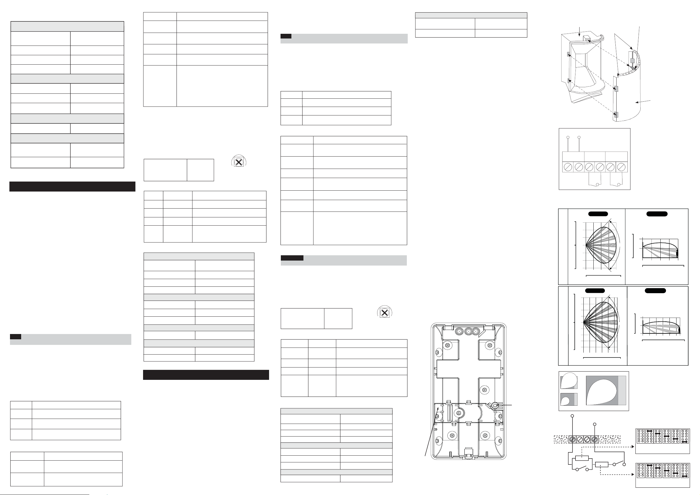
Figure 1.
Back cover - Knockouts
Range
Adjustment Bolt
Thread
Figure 6.
Schematic of EOL Resistors
Tamper / Alarm EOL Jumpers
Figure 2.
Lens Replacement
Sleeve
12VDC
+ 12 - ALARM TAMPER
Cut
Corners
Short Pin
(Facing upwards)
Figure 3.
Terminal Wiring
Figure 4.
iWISE 811DTPT Lenses and Microwave Range
Feet
20
6
4
10
2
0
0
2
RL 108PTH
10
4
6
20
Meters
Feet
Feet
30
8
20
6
4
10
2
0
0
2
10
RL 111H
4
20
6
8
30
Meters
Feet
TOP VIEW
90°
02468
0102030
TOP VIEW
90°
024681011
010203040
Feet
20
10
0
Feet
20
10
SIDE VIEW
4
2
0
0
Meters
Feet
0102030
SIDE VIEW
4
2
0
0
2
0
Meters
Feet
010203040
Figure 5.
MW range adjustment
1
A
2
PANEL DEOL
+12- ALARM TAMPER FAULT/AM LED
ALARM
3
TAMPER
B
J1 - ALARM EOL JUMPERS
1K 2.2K 4.7K 5.6K 6.8K
No
Resistor
(Factory Settings)
J2 - TAMPER EOL JUMPERS
1K 2.2K 4.7K 5.6K 6.8K
No
Resistor
(Factory Settings)
Lens
4682
468
10 11
 Loading...