

Page 1
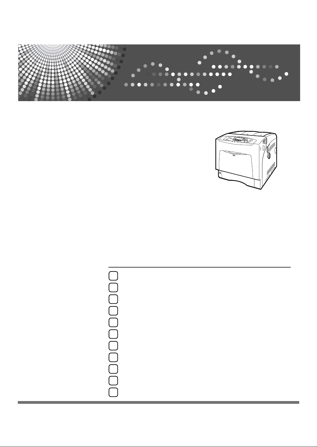
Guide to the Printer
1
Installing Options
2
Hardware Guide
Connecting the Printer
3
Configuration
4
Paper and Other Media
5
Replacing Consumables and Maintenance Kit
6
Cleaning the Printer
7
Adjusting the Printer
8
Troubleshooting
9
Removing Misfed Paper
10
Appendix
11
Read this manual carefully before you use this machine and keep it handy for future reference. For safe and correct use, be sure to read the
Safety Information before using the machine.
Page 2

Page 3

Trademarks
Microsoft, Windows and Windows NT are registered trademarks of Microsoft
Corporation in the United States and/or other countries.
Adobe
istered trademarks of Adobe Systems Incorporated.
PCL
Apple, AppleTalk, EtherTalk, Macintosh, Mac OS, and True Type are trademarks of Apple Computer, Inc., registered in the U.S. and other countries.
IPS-PRINT Printer Language Emulation Copyright© 1999-2000 Oak Technology, Inc., All rights reserved.
The Bluetooth
any use of such marks by Ricoh Company, Ltd. is under license.
NetWare is a registered trademark of Novell, Inc.
PictBridge is a trademark.
Other product names used herein are for identification purposes only and might
be trademarks of their respective companies. We disclaim any and all rights to
those marks.
The proper names of the Windows operating systems are as follows:
•Microsoft
•Microsoft
•Microsoft
• The product names of Windows
• The product names of Windows
• The product names of Windows Server
• The product names of Windows NT
®
, PostScript®, Acrobat®, PageMaker® and Adobe Type Manager are reg-
®
is a registered trademark of Hewlett-Packard Company.
®
word mark and logos are owned by the Bluetooth SIG, Inc. and
®
Windows® 95 operating system
®
Windows® 98 operating system
®
Windows® Millennium Edition (Windows Me)
®
2000 are as follows:
®
XP are as follows:
TM
2003 are as follows:
®
4.0 are as follows:
Microsoft
Microsoft
Microsoft
Microsoft
Microsoft
Microsoft
Microsoft
Microsoft
Microsoft
Microsoft
®
Windows® 2000 Advanced Server
®
Windows® 2000 Server
®
Windows® 2000 Professional
®
Windows® XP Professional
®
Windows® XP Home Edition
®
Windows ServerTM 2003 Standard Edition
®
Windows ServerTM 2003 Enterprise Edition
®
Windows ServerTM 2003 Web Edition
®
Windows NT® Server 4.0
®
Windows NT® Workstation 4.0
i
Page 4
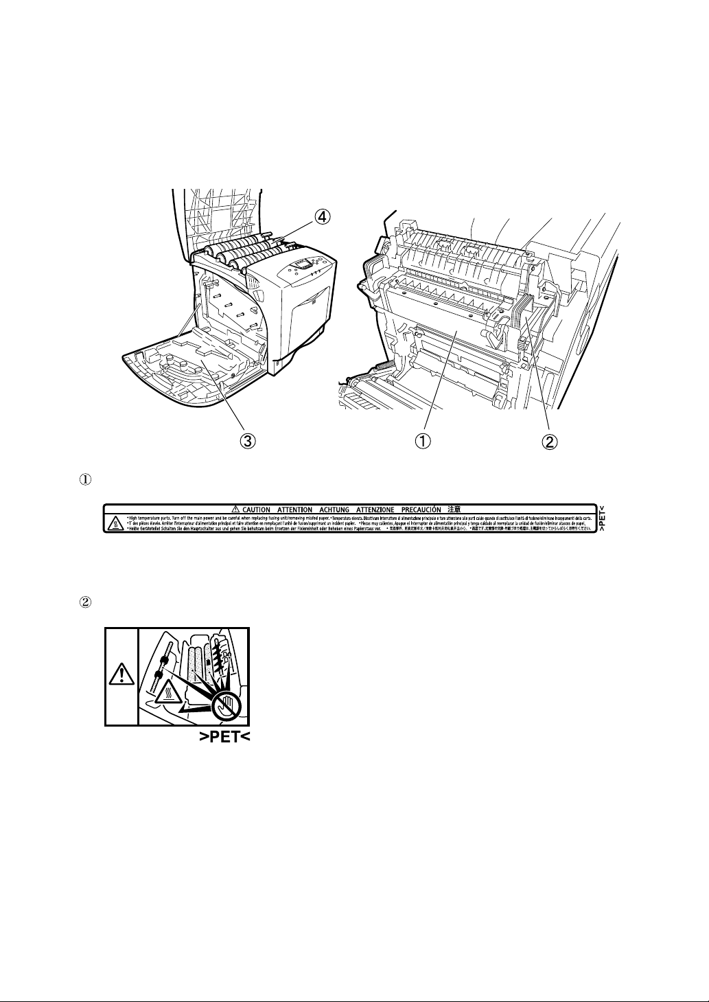
Positions of RWARNING and RCAUTION
labels
This machine has labels for RWARNING and RCAUTION at the positions
shown below. For safety, please follow the instructions and handle the machine
as indicated.
AQC0
High temperature parts. Turn off the main power and be careful when replacing
fusing unit/removing misfed paper.
The inside of this printer becomes very hot. Do not touch parts labelled “v” (indicating a hot surface). Touching these parts will result in burns.
ii
Page 5
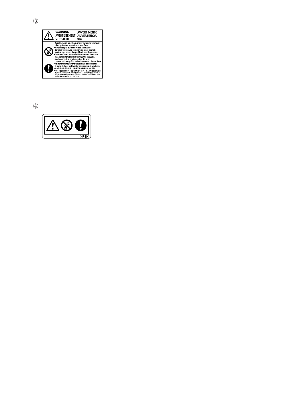
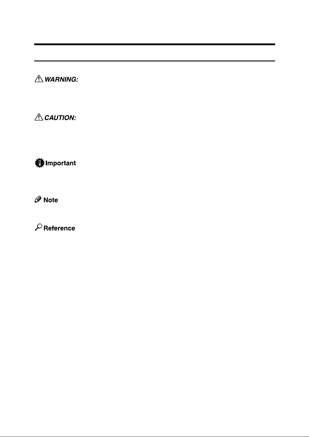
Do not incinerate used toner or toner containers. Toner dust might ignite when
exposed to an open flame.
Do not incinerate spilled toner or used toner. Toner dust is flammable and might
ignite when exposed to an open flame.
Disposal should take place at an authorized dealer or an appropriate collection
site.
If you dispose of the used toner containers yourself, dispose of them according
to local regulations.
iii
Page 6

Manuals for This Printer
For particular functions, see the relevant parts of the manual.
❖ Safety Information
Provides information on safe usage of this machine.
To avoid injury and prevent damage to the machine, be sure to read this.
❖ Quick Installation Guide
Contains procedures for removing the printer from its box, connecting it to a
computer, and installing its driver.
❖ Hardware Guide
Contains information about paper and procedures such as installing options,
replacing consumables, responding to error messages, and resolving jams.
❖ Software Guide
Contain procedures for using this machine in a network environment, utilizing the software, and using security functions.
❖ Security Guide
This manual is for administrators of the machine. It explains security functions that the administrators can use to protect data from being tampered, or
prevent the machine from unauthorized use. Also refer to this manual for the
procedures for registering administrators, as well as setting user and administrator authentication.
iv
Page 7
How to Read This Manual
Symbols
This manual uses the following symbols:
Indicates important safety notes.
Ignoring these notes could result in serious injury or death. Be sure to read these
notes. They can be found in the Safety Information.
Indicates important safety notes.
Ignoring these notes could result in moderate or minor injury, or damage to the
machine or to property. Be sure to read these notes. They can be found in the
Safety Information.
Indicates points to pay attention to when using the machine, and explanations
of likely causes of paper misfeeds, damage to originals, or loss of data. Be sure
to read these explanations.
Indicates supplementary explanations of the machine’s functions, and instructions on resolving user errors.
This symbol is located at the end of sections. It indicates where you can find further relevant information.
[ ]
Indicates the names of keys that appear on the machine’s display panel.
{ }
Indicates the names of keys on the machine’s control panel.
v
Page 8
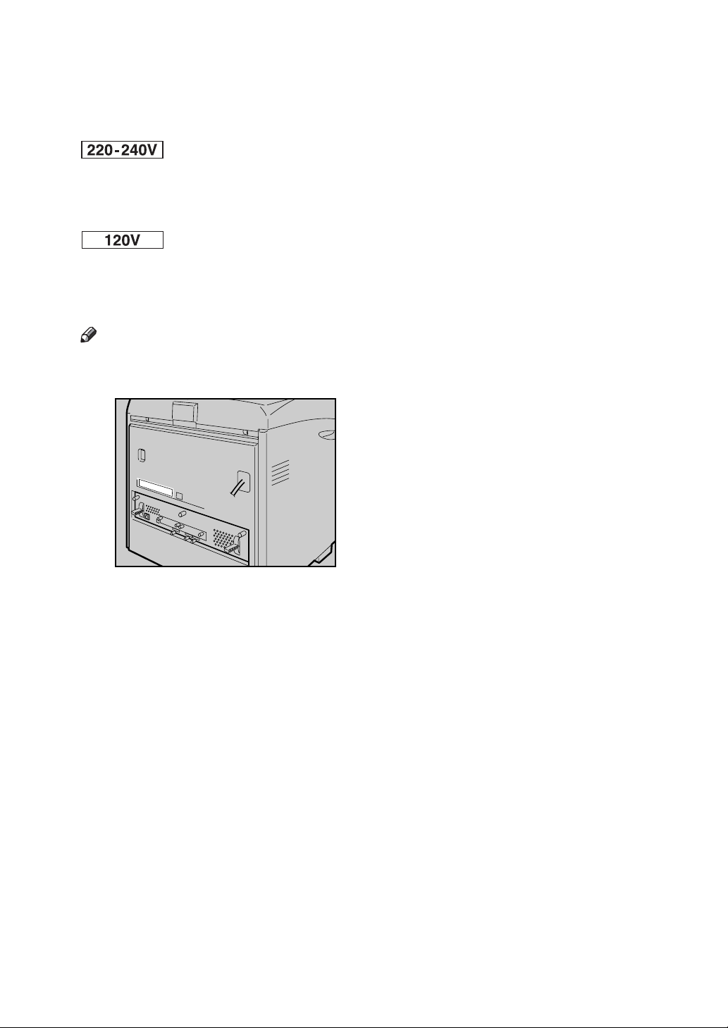
Description for the Specified Model
In this manual, the following items explain about the printer for the specified
models:
This explains about the 220–240 V model printer. You can identify the model by
checking the label on the rear of the printer.
Read if you purchase this model.
This explains about the 120 V model printer. You can identify the model by
checking the label on the rear of the printer.
Read if you purchase this model.
Note
❒ You can identify the printer's model by checking the label on the rear of the
printer as shown.
AQC065S
vi
Page 9

Installing the Operating Instructions
The CD-ROM “Manuals” provided with the printer contains an HTML Operating Instructions Manual in HTML version. Follow this instructions to install it.
Important
❒ System Requirements :
• Windows 95/98/Me, Windows 2000/XP, Windows Server 2003 or Windows NT4.0.
• 800 × 600 or higher monitor resolution.
❒ Web Browsers :
• Microsoft Internet Explorer 5.5 SP2 or higher
• Firefox 1.0 or higher
A Quit all applications currently running.
B Insert the CD-ROM “Manuals” into the CD-ROM drive.
The installer starts.
Auto Run may not work under certain operating system setting. If this is the
case, launch “Setup.exe” on the CD-ROM root directory.
C Select an interface language, and then click [OK].
D Click [Install manuals].
E Follow the instructions on the screen to complete the installation.
F Click [Finish] when the installation is completed.
G Click [Exit].
Note
❒ Auto Run may not work under certain operating system setting. If this is
the case, copy all data on the CD-ROM root directory to your hard disk
drive, and then launch “Setup.exe” to start the installation.
❒ To uninstall the Operating Instructions Manual, select [Programs] in the
[Start] menu, select your printer driver, and then click [uninstall]. You can
uninstall each Manual Guide separately.
❒ If you are using an incompatible Web browser and the simpler version of
the Operating Instructions Manual does not display correctly, open the
folder “MANUALLANG (language) \ (manual name) unv” on the CDROM “Manuals”, and then double-click on “index.htm”.
vii
Page 10

TABLE OF CONTENTS
Trademarks..............................................................................................................i
Positions of RWARNING and RCAUTION labels ..............................................ii
Manuals for This Printer.......................................................................................iv
How to Read This Manual ..................................................................................... v
Symbols ..................................................................................................................... v
Description for the Specified Model....................................................................vi
Installing the Operating Instructions .................................................................vii
1. Guide to the Printer
Exterior: Front View...............................................................................................1
Exterior: Rear View ................................................................................................3
Inside.......................................................................................................................4
Control Panel..........................................................................................................5
Display Panel..........................................................................................................7
Reading the Display and Using Keys.........................................................................7
2. Installing Options
Available Options...................................................................................................9
Option List .................................................................................................................. 9
Option Installation Flow Chart ..................................................................................10
Installing Options......................................................................................................11
Caution when re-installing the controller board........................................................13
Attaching Paper Feed Unit Type 4000................................................................14
Attaching Memory Unit Type D 128MB, Memory Unit Type E 256MB (SDRAM
Module) ...............................................................................................................17
Attaching User Account Enhance Unit Type E .................................................22
Attaching Hard Disk Drive Type 4000 ................................................................27
Attaching IEEE 802.11b Interface Unit ...............................................................33
Attaching Bluetooth Interface Unit Type 3245 ..................................................36
Attaching IEEE 1284 Interface Board Type A....................................................39
Attaching the USB Host Interface Board Type A ..............................................41
Attaching Gigabit Ethernet Board Type A .........................................................43
Attaching Data Overwrite Security Unit Type E ................................................46
Attaching the Camera Direct Print Card ............................................................48
Attaching VM Card Type D..................................................................................50
Attaching Data Storage Card Type A .................................................................52
3. Connecting the Printer
Network Connection ............................................................................................55
Reading the LED Lamps .......................................................................................... 57
USB Connection...................................................................................................58
Connecting a digital camera ...............................................................................59
Parallel Connection ............................................................................................. 61
viii
Page 11

4. Configuration
Ethernet Configuration........................................................................................63
Using DHCP - Detecting the Network Address Automatically..................................67
Making Network Settings for Using Netware............................................................ 69
IEEE 802.11b (Wireless LAN) Configuration .....................................................71
5. Paper and Other Media
Paper and Other Media Supported by This Printer...........................................77
Paper Recommendations....................................................................................81
Loading Paper..........................................................................................................81
Storing Paper ...........................................................................................................81
Types of Paper and Other Media ............................................................................. 82
Paper not supported by this printer.......................................................................... 87
Print Area .................................................................................................................88
Loading Paper ......................................................................................................89
Loading Paper in Tray 1 and the optional paper feed unit .......................................89
Loading Paper in the Bypass Tray ...........................................................................97
Switching between Paper Trays.............................................................................104
6. Replacing Consumables and Maintenance Kit
Replacing the Toner Cartridge ......................................................................... 105
Replacing the Photo Conductor Unit ............................................................... 109
Replacing the Intermediate Transfer Unit........................................................115
Replacing the Waste Toner Bottle....................................................................120
Replacing the Maintenance Kit.........................................................................123
Before Replacing....................................................................................................123
Replacing the Friction Pad .....................................................................................124
Replacing the Paper Feed Roller........................................................................... 126
Replacing the Transfer Roller ................................................................................128
Replacing the Fusing Unit ......................................................................................130
Replacing the Dustproof Filter................................................................................132
7. Cleaning the Printer
Cautions to Take When Cleaning .....................................................................135
Cleaning the Friction Pad..................................................................................136
Cleaning the Paper Feed Roller........................................................................138
Cleaning the Registration Roller ......................................................................141
8. Adjusting the Printer
Adjusting the Color Registration......................................................................143
Correcting the Color Gradation ........................................................................145
Set the Gradation Correction Value ....................................................................... 146
Viewing the Color Calibration Sample Sheet and Gradation Correction Sheet ..... 149
Resetting the gradation correction value to the initial value ................................... 151
Adjusting Tray Registration..............................................................................152
ix
Page 12

9. Troubleshooting
Error & Status Messages on the Control Panel ..............................................155
Panel Tone..........................................................................................................157
Printer Does Not Print ....................................................................................... 158
Checking the port connection.................................................................................160
Other Printing Problems ................................................................................... 162
Additional Troubleshooting ..............................................................................168
10.Removing Misfed Paper
Removing Misfed Paper ....................................................................................171
When the Paper Misfeed Message Appears (Cover A)...................................172
When the Paper Misfeed Message Appears (Cover Z)................................... 175
11.Appendix
Moving and Transporting the Printer............................................................... 177
Moving the Printer ..................................................................................................178
Consumables ..................................................................................................... 179
Toner Cartridge ......................................................................................................179
Waste Toner Bottle ................................................................................................180
Photo Conductor Unit.............................................................................................180
Intermediate Transfer Unit (Transfer Unit) .............................................................181
Maintenance Kit .....................................................................................................181
Specifications.....................................................................................................182
Mainframe ..............................................................................................................182
Options................................................................................................................... 185
INDEX....................................................................................................... 189
x
Page 13
1. Guide to the Printer
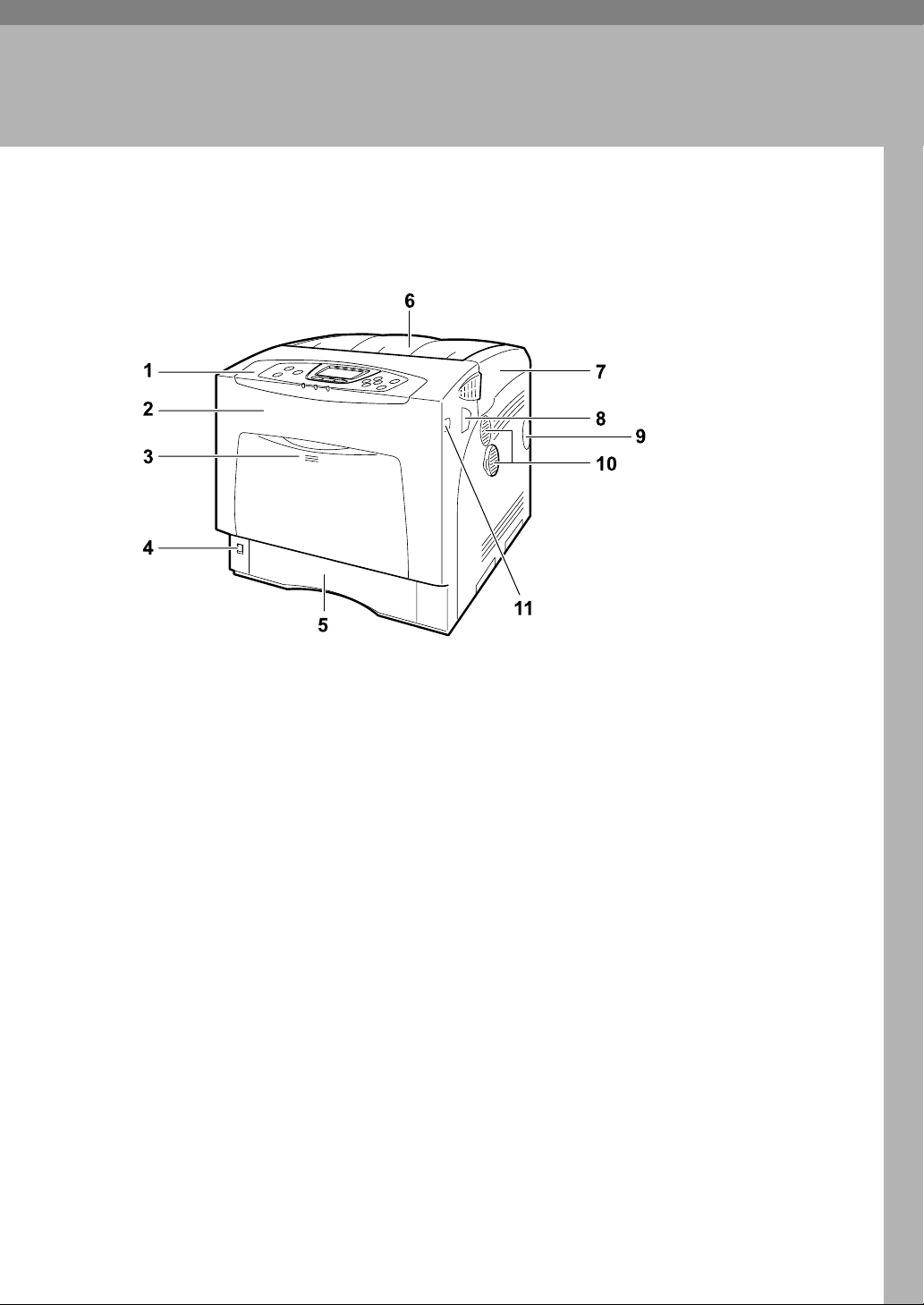
Exterior: Front View
1. Control Panel
Contains keys for printer control and a
display that shows the printer status.
2. Front Cover
Open the front cover to replace the fusing
unit or transfer roller, or to remove
jammed paper.
The front cover can be opened in two
ways:
To replace the fusing unit or roller, pull
the levers marked “A” on either side of
the printer. To remove jammed paper,
press the button marked “Z” on the right
side of the printer.
3. Bypass Tray
Up to 100 sheets of plain paper can be
loaded.
AQC021S
4. Power Switch
Use this switch to turn the power on and
off.
5. Tray 1
Up to 550 sheets of plain paper can be
loaded.
6. Standard Tray
Output is stacked here with the print side
down.
7. Top Cover
Open this cover when replacing the toner
cartridge.
8. Front Cover (A) Open Levers
9. Intake Port
1
Page 14
1
Guide to the Printer
10. Ventilator
Releases heat from internal components
to prevent overheating. Malfunctions occur if the vent is blocked or obstructed.
The dustproof filter needs to be replaced
regularly for proper maintenance.
11. Front Cover (Z) Open Button
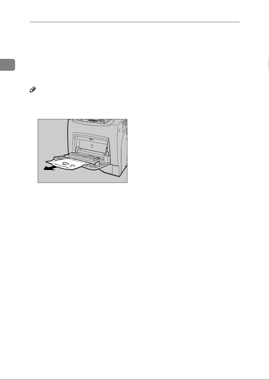
Note
❒ When setting paper larger than A5 K, pull out the paper extender as shown.
For details about the sizes and types of paper that can be used, see p.77 “Paper
and Other Media Supported by This Printer”.
AQC022S
2
Page 15
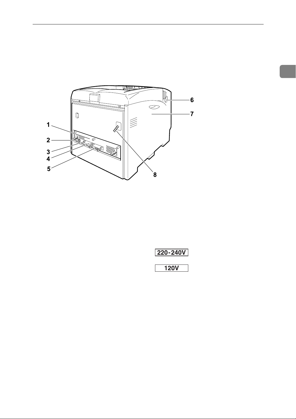
Exterior: Rear View
Exterior: Rear View
1
AQC200S
1. Controller Board
Slide this out to install options such as the
memory unit, user account enhance unit
or printer hard disk. Plug cables such as
the USB cable and Ethernet cable into
their connectors.
2. Ethernet Port
Use a network interface cable to connect
the printer to the network.
3. USB Port
Use a USB cable to connect the printer to
the host computer.
4. Optional Interface Board Slots
Insert an optional IEEE 802.11b interface
unit, wireless interface board, or 1284 interface board in this slot. Up to two interface board can be inserted at a time.
5. Expansion Card Slots
Install expansion cards in these slots.
There are three slots.
When you use the expansion card, use
the center slot.
6. Front Cover (A) Open Levers
7. Left Cover
Open this cover when replacing the photo conductor unit (PCU), intermediate
transfer unit or waste toner cartridge.
8. Power Cable
The power cable is separat-
ed. Connect the power cable to the printer.
The power cable is fixed to the back side.
3
Page 16
1
Guide to the Printer
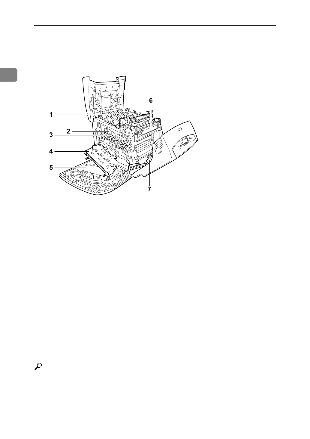
Inside
AQC023S
1. Toner Cartridge
Loads from the printer rear, in the order
of yellow (Y), cyan (C), magenta (M), and
black (K).
If the message which prompts you to replace toner appears on the screen, replace
the indicated color of the toner cartridge.
2. Intermediate Transfer Unit
(Transfer Unit)
If the message which prompts you to replace it appears on the display, replace
the transfer unit .
3. Photo Conductor Unit
If the message which prompts you to replace it appears on the display, replace
the photo conductor unit.
Reference
For details about the messages which appear on the screen to prompt you to
replace the units, see p.155 “Error & Status Messages on the Control Panel”.
4. Inner Cover
Open this when replacing the photo conductor units or intermediate transfer
unit.
5. Waste Toner Bottle
Collects toner that is wasted during
printing.
If the message which prompts you to replace it appears on the display, replace
the waste toner bottle.
6. Fusing Unit
If the message which prompts you to replace it appears on the display, replace
the fusing unit.
7. Transfer Roller
If the message which prompts you to replace it appears on the display, replace
the transfer roller.
4
Page 17
Control Panel
Control Panel
1
AQC024S
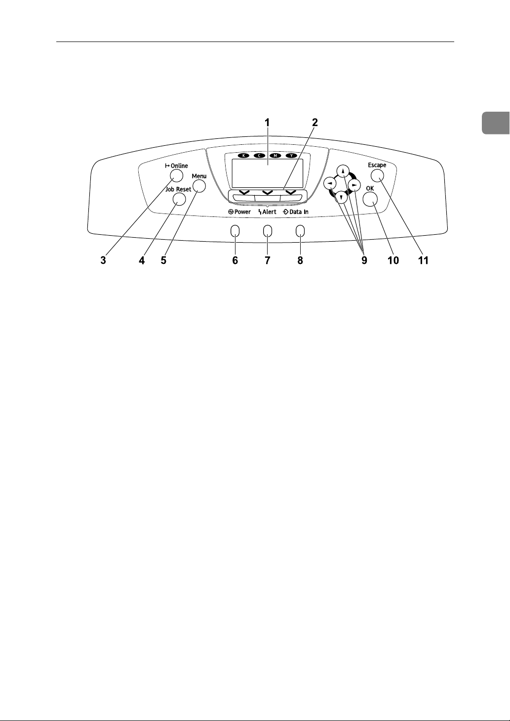
1. Display
Displays current printer status and error
messages.
For details about error messages, see
p.155 “Error & Status Messages on the
Control Panel”.
2. Selection keys
Correspond to the function items at the
bottom line on the display.
Example: In the initial screen, when the
instruction “press [Option]” appears in
this manual, press the left selection key.
3. {Online} key
Indicates whether the printer is online or
offline. Press this to switch between online and offline.
When the lamp is lit, the printer is online,
enabling data reception from the host
computer.
When the lamp is unlit, the printer is offline, disabling data reception from the
host computer.
Press to return to the ready condition.
4. {Job Reset} key
When the printer is online, press this key
to cancel an ongoing print job.
5. {Menu} key
Press this key to make and check the current printer settings.
For details, See “Making Printer Settings
Using the Control Panel”, Software
Guide.
6. Power indicator
This indicator remains lit while the power is on. It is unlit when the power is off
or while the printer is in the Energy Saver
mode.
7. Alert indicator
Lights up whenever a printer error occurs. A red light indicates an error has occurred that makes printing impossible;
the yellow light indicates a potential error during printing.
If the red light is on, follow the instructions that appear on the display.
8. Data In indicator
Blinks when the printer is receiving data
from a computer. The Data In indicator is
lit if there is data to be printed.
9. Scroll keys
Press to move the cursor in each direction, step by step.
When the {U}, {T}, {V}, or {W} key appears in this manual, press the scroll key
of the same direction.
5
Page 18

1
Guide to the Printer
10. {OK} key
Press this key to execute menu items selected on the display.
11. {Escape} key
Press this key to return to the previous
condition on the display.
6
Page 19
Display Panel
Display Panel
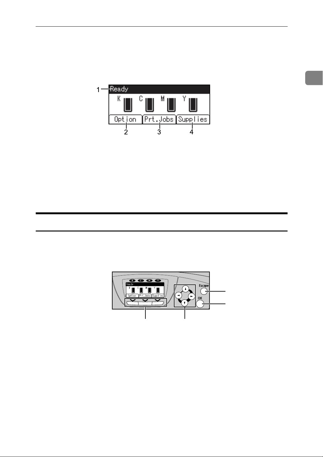
This section describes configuration using the display panel on the initial screen.
AQC060S
1
1. Operational status or messages
Displays current machine status, such as
“Ready”, “Offline”, and “Printing...”.
2. [Option]
Press to display the status of options installed in the printer.
3. [Prt.Jobs]
Press to display print jobs sent from a
computer.
For details, see Software Guide.
4. [Supplies]
Press to display the menu of supplies fir
the printer.
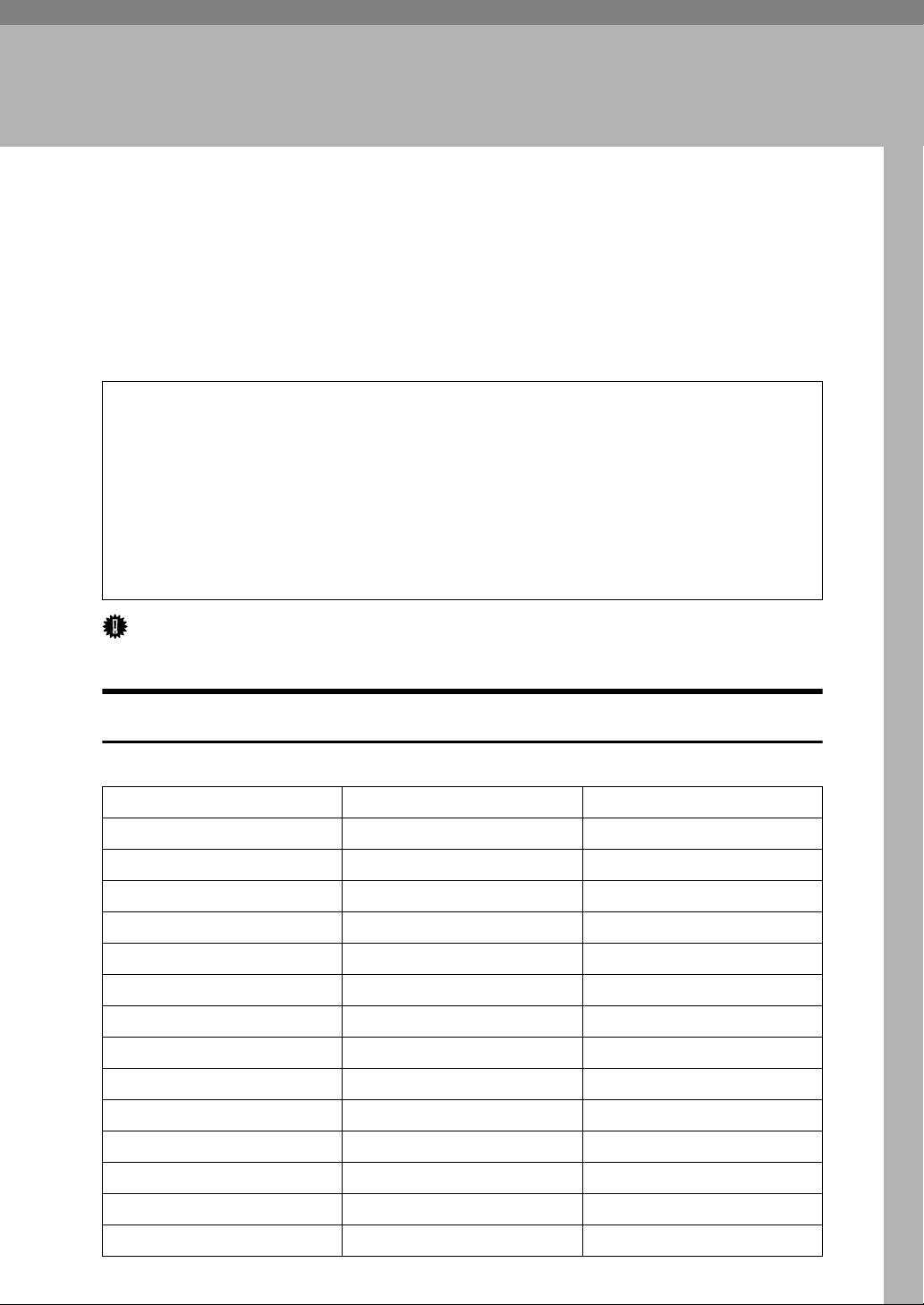
Reading the Display and Using Keys
This section explains how to read the display and using the selection key for the
initial display.
1
2
34
AQC061S
1. {Escape} key
Press to cancel an operation or return to
the previous display.
2. {OK} key
Press to set a selected item or entered numeric value.
3. Scroll keys
Press to move the cursor in each direction, step by step.
When the {U}, {T}, {V}, or {W} key appears in this manual, press the scroll key
of the same direction.
4. Selection keys
Correspond to the function items at the
bottom line on the display.
Example: In the initial screen, when the
instruction “press [Option]” appears in
this manual, press the left selection key.
7
Page 20

1
Guide to the Printer
8
Page 21
2. Installing Options
R
Available Options
This section describes how to install options.
By installing options, you can improve the printer performance and have an expanded variety of features to use. For the specifications of each option, see p.182
“Specifications”.
CAUTION:
• Before installing options, the machine should be turned off and unplugged
for at least an hour. Components inside the machine become very hot, and
can cause a burn if touched.
• Before moving the machine, unplug the power cable from the outlet. If the
cable is unplugged abruptly, it could become damaged. Damaged plugs or
cables can cause an electrical or fire hazard.
• When lifting the machine, use the grips on both sides. The machine could
break or cause an injury if dropped.
Important
❒ The voltage rating of the connector for options is 24 V DC or less.
Option List
The following is a list of options for this printer.
The 25 ppm model printer The 30 ppm model printer
Paper Feed Unit Type 4000 Available Available
Hard Disk Drive Type 4000 Available Available
Memory Unit Type D 128MB Available Available
Memory Unit Type E 256MB Available Available
IEEE 802.11b Interface Unit Available Available
IEEE 1284 Interface Board Type A
Bluetooth Interface Unit Type 3245
User Account Enhance Unit Type E
USB Host Interface Board Type A
Gigabit Ethernet Board Type A Available Available
Camera Direct Print Card Type B
Available Available
Available Available
Available Available
Available Available
Available Available
Data Overwrite Security Unit Type E
VM Card Type D Available Available
Data Storage Card Type A Available Available
Available Available
9
Page 22

Installing Options
Option Installation Flow Chart
Installing multiple options in the following order is recommended:
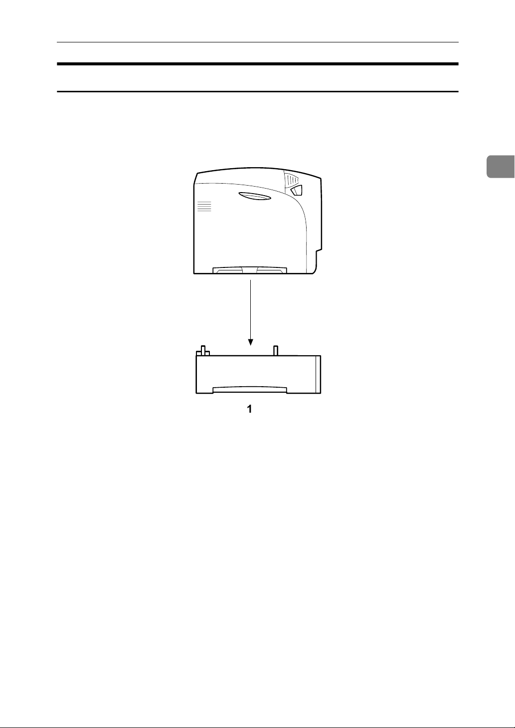
A Attach the paper feed unit (Paper Feed Unit Type 4000).
Attach the paper feed units to the bottom of the printer.
2
You can attach up to two paper feed units. Up to 1750 sheets of paper can be
loaded in total.
B Install the SDRAM module (Memory Unit Type D 128MB, Memory Unit
Type E 256MB).
Install the module to the SDRAM module slot on the controller board.
There are two types of memory unit: 128 MB and 256 MB.
C Install User Account Enhance Unit (User Account Enhance Unit Type E).
Install the module to the User Account Enhance Unit slot of the controller
board.
D Install the hard disk drive (Hard Disk Drive Type 4000).
Install the hard disk drive to the controller board.
E Install the IEEE 1284 interface board, IEEE 802.11b interface unit, Bluetooth
interface unit, USB host interface board, or Gigabit Ethernet board.
Install the IEEE 1284 interface board, IEEE 802.11b interface unit, Bluetooth
interface unit, USB host interface board, or Gigabit Ethernet board on the controller board.
Up to two of the followings can be installed:
• IEEE 1284 Interface Board Type A
• IEEE 802.11b Interface Unit
• Bluetooth Interface Unit Type 3245
• USB Host Interface Board Type A
• Gigabit Ethernet Board Type A
F Install the security unit (Data Overwrite Security Unit Type E, Data Storage
Card Type A), the Camera Direct Print card (Camera Direct Print Card Type
B), or the VM card (VM Card Type D).
Insert these units into the SD card slot on the controller board.
10
Page 23
Installing Options
Install options in the positions shown in the illustration.
❖ Exterior
Available Options
2
1. Paper Feed Unit Type 4000
Loads up to 550 sheets of paper.
Up to two paper feed units, can be in-
stalled on the printer. Installed tray
units are identified as “Tray 2” and
“Tray 3”.
See p.14 “Attaching Paper Feed Unit
Type 4000”.
AET061S
11
Page 24
2
Installing Options
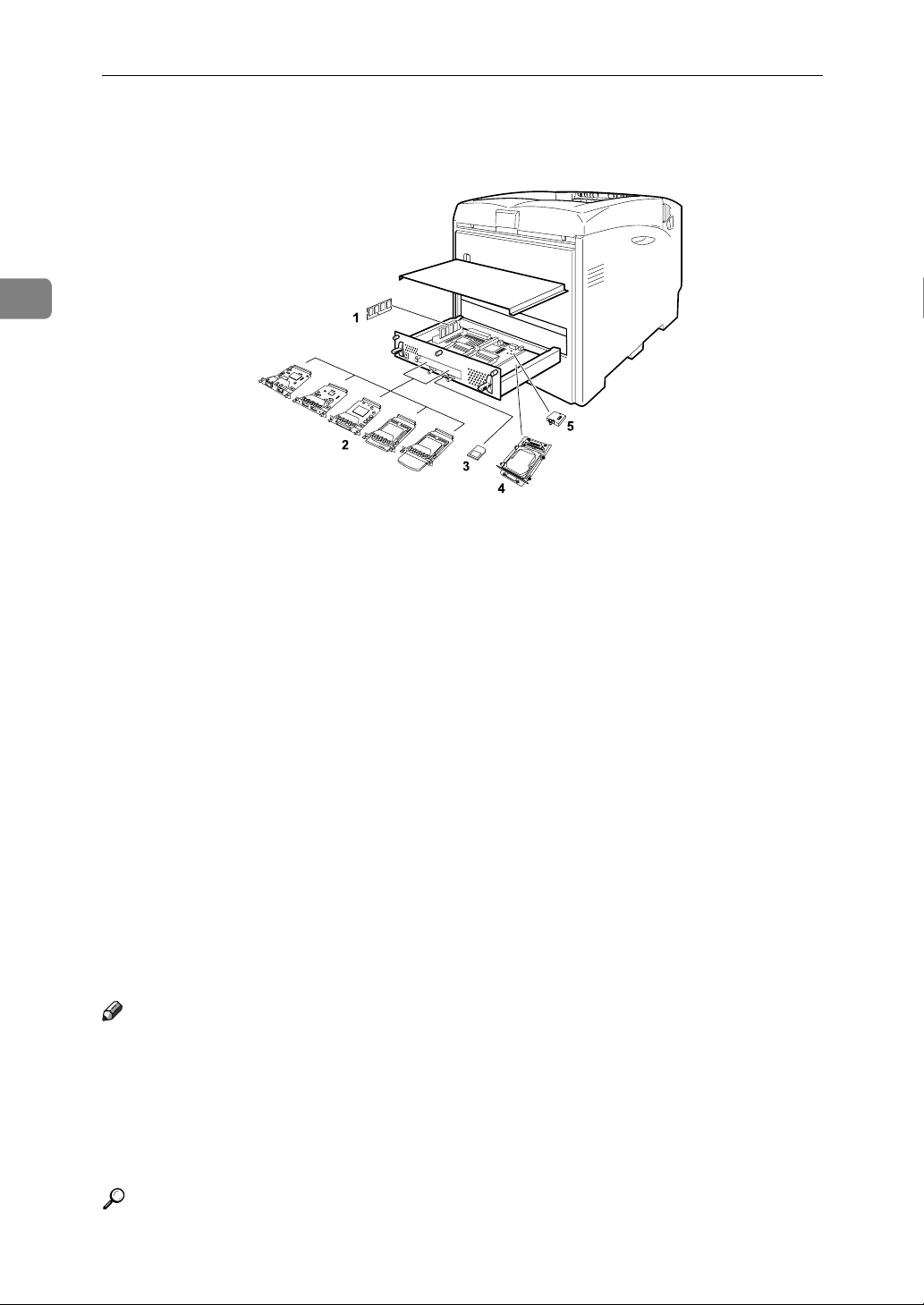
❖ Interior
AQC040S
1. Memory Unit Type D 128MB/Mem-
ory Unit Type E 256MB (SDRAM module)
Install 128 MB or 256 MB SDRAM
module into the controller board slot.
See p.17 “Attaching Memory Unit
Type D 128MB, Memory Unit Type E
256MB (SDRAM Module)”.
2. Optional boards
See p.33 “Attaching IEEE 802.11b Interface Unit”.
See p.36 “Attaching Bluetooth Interface Unit Type 3245”.
See p.39 “Attaching IEEE 1284 Interface Board Type A”.
See p.41 “Attaching the USB Host Interface Board Type A”.
See p.43 “Attaching Gigabit Ethernet
Board Type A”.
Note
3. Optional units
See p.46 “Attaching Data Overwrite
Security Unit Type E”.
See p.48 “Attaching the Camera Direct
Print Card”.
See p.50 “Attaching VM Card Type
D”.
See p.52 “Attaching Data Storage
Card Type A”.
4. Hard Disk Drive Type 4000
See p.27 “Attaching Hard Disk Drive
Type 4000”.
5. User Account Enhance Unit Type E
See p.22 “Attaching User Account Enhance Unit Type E”.
❒ You can have two of the following types of extension board installed at the
same time: IEEE 802.11b Interface Unit, Bluetooth Interface Unit Type 3245,
IEEE 1284 Interface Board Type A, USB Host Interface Board Type A, and Gigabit Ethernet Board Type A.
❒ Some printer models come with the Expansion Hard Disk Drive Unit and
Data Overwrite Security Unit installed as default.
12
Reference
For the specifications of each option, see p.182 “Specifications”.
Page 25
Available Options
Caution when re-installing the controller board
This section describes handling the controller board when installing options.
If you slide out the controller board to install the SDRAM module, the user account enhance unit, or the printer hard disk, carefully follow the instruction below to re-install the controller board.
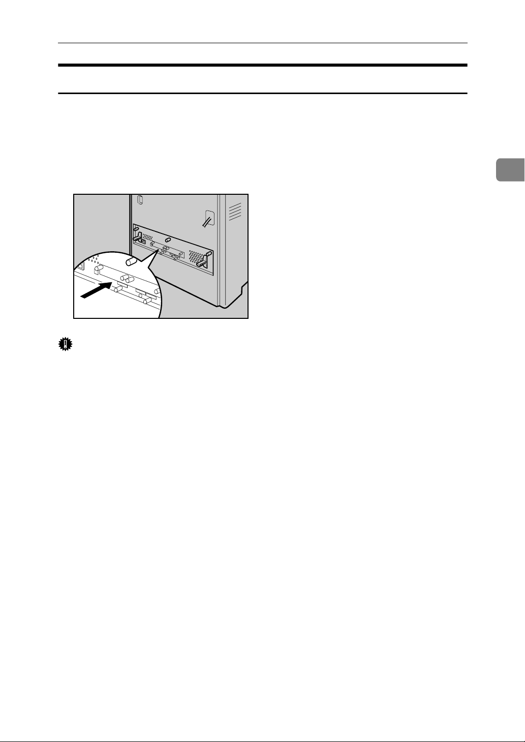
• Re-install the controller board into the printer by pushing the bottom center
area of the board, as shown in the illustration.
AQC004S
Important
❒ The following may occur if the controller board is not properly installed:
• all control panel indicators are lit.
• no control panel indicators is lit.
• the “SC670” error message appears on the display.
2
13
Page 26
2
R
R
Installing Options
Attaching Paper Feed Unit Type 4000
When installing multiple options, install the paper feed unit first.
CAUTION:
• The printer weights approximately 50 kg (110.3 lb.). When moving the printer, use the inset grips on both sides, and lift slowly. The printer will break or
cause injury if dropped.
CAUTION:
• Lifting the paper feed unit carelessly or dropping it may cause injury.
Important
❒ Up to two paper feed units can be attached to the printer.
❒ When two paper feed units are installed, they are detected as “Tray 2” and
“Tray 3” starting from the upper unit.
❒ Before using the new paper feed unit, you must make settings in the printer
driver.
❒ Check the printer nameplate to confirm the model code.
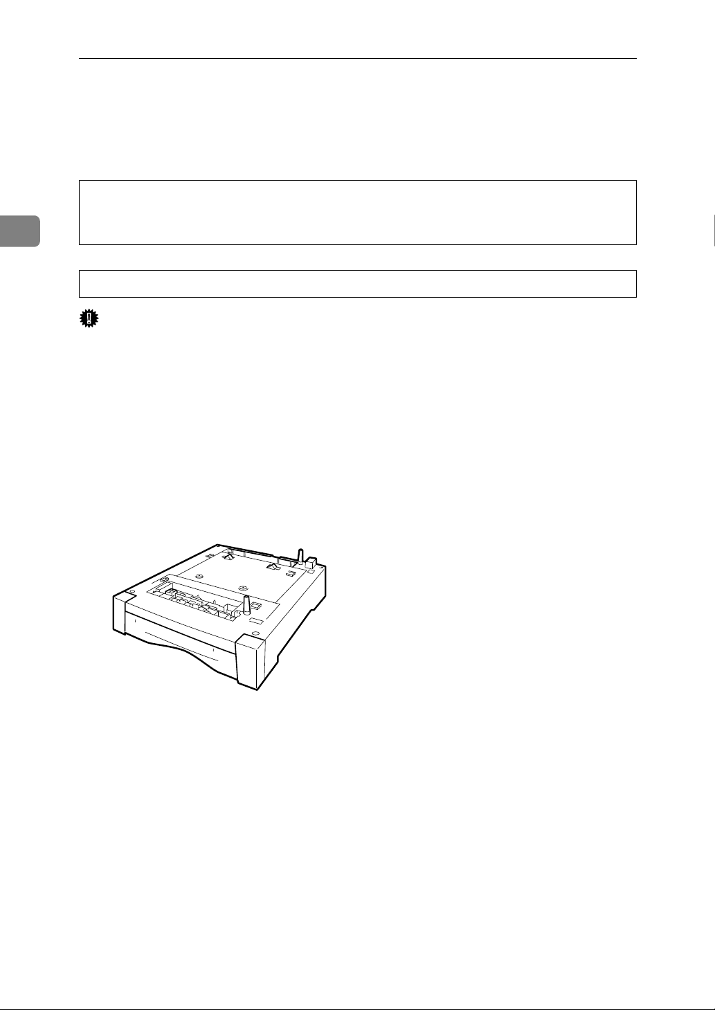
A Check the package contains the following:
❖ Paper Feed Unit (including a paper tray)
AET108S
B Turn off the power, and then unplug the power cable.
C Remove the orange fastening tapes from the paper feed unit.
14
Page 27

Attaching Paper Feed Unit Type 4000
D Lift the printer using the inset grips on both sides of the printer.
AQC031S
Important
❒ The printer should always be lifted by at least two people.
E Align the printer with the two upright pins on the paper feed unit and then
lower the printer slowly.
2
AET074S
When installing two paper feed units, connect the two units first using the
same procedure below before connecting the units to the printer.
AET075S
15
Page 28

2
Installing Options
Note
❒ When moving the printer, remove the paper feed unit.
❒ After finishing installation, you can check whether the paper feed unit is
properly installed: Print the configuration page from the [List/Test Print]
menu. If it is installed properly, “Tray 2” or “Tray 2”, “Tray 3” will appear
for “Connection Equipment” on the configuration page.
❒ If the paper feed unit is not installed properly, reinstall it following this
procedure. If you cannot install it properly even after attempting reinstallation, contact your sales or service representative.
Reference
For printing the configuration page, see “Test Printing”, Quick Installation
Guide.
For loading paper onto the paper tray, see p.89 “Loading Paper”.
When adjusting the printing position, see p.152 “Adjusting Tray Registration”.
16
Page 29
Attaching Memory Unit Type D 128MB, Memory Unit Type E 256MB (SDRAM Module)
R
Attaching Memory Unit Type D 128MB,
Memory Unit Type E 256MB (SDRAM Module)
CAUTION:
• Do not touch the inside of the controller board compartment. Doing so may
cause a malfunction or a burn.
Important
❒ Before touching the memory unit, ground yourself by touching something
metal to discharge any static electricity. Static electricity can damage the
memory unit.
❒ Do not subject the memory unit to physical shocks.
❒ Available memory varies depending on a model type.
❒ Before using the new memory unit, Be sure to make settings in the printer
driver.
A Turn off the power, and then unplug the power cable.
2
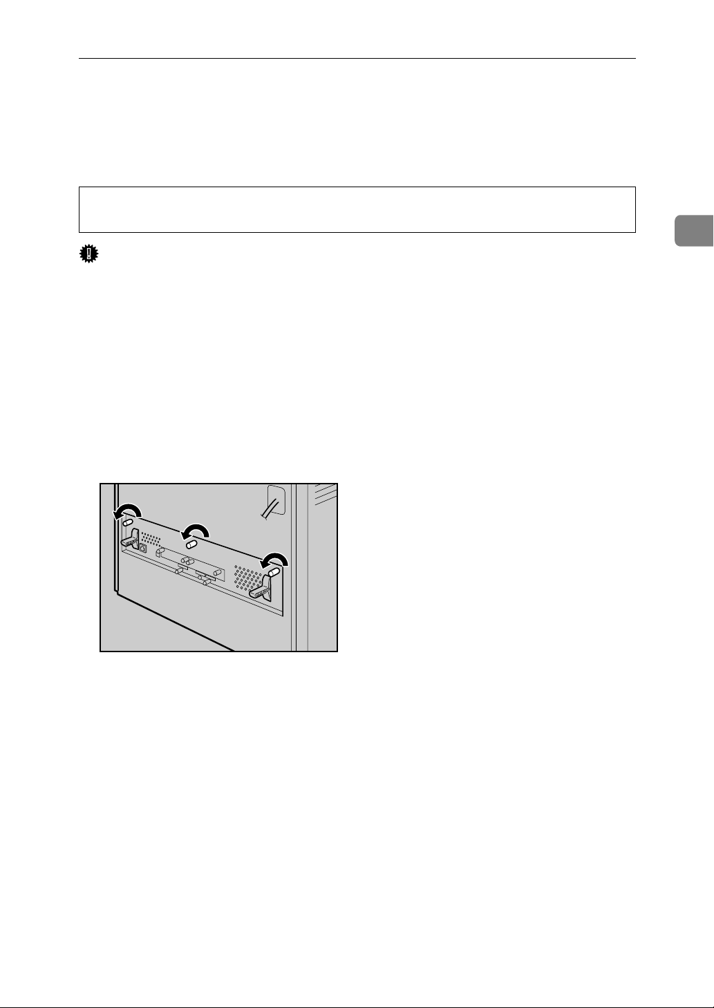
B Loosen the three screws securing the controller board.
AQC630S
The screws cannot be fully removed.
17
Page 30
2
Installing Options
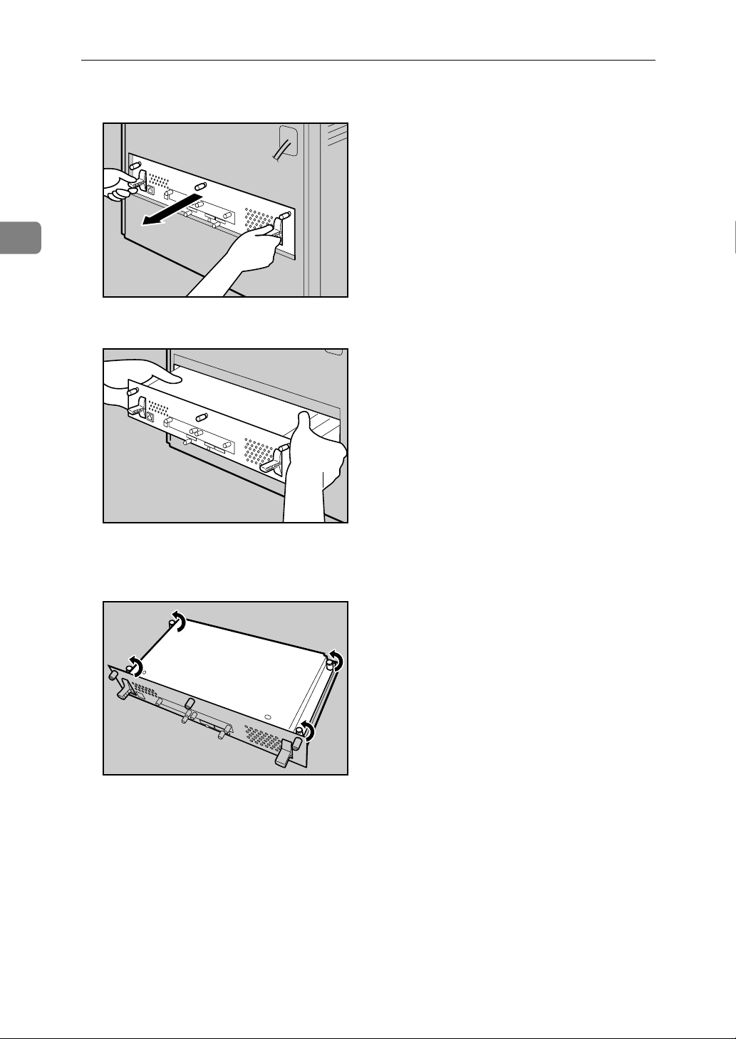
C Grasp the handles and carefully pull out the controller board.
AQC640S
Using both hands, slide the controller board completely out.
AQC650S
D Place the controller board on a flat surface, and then loosen the four screws
to remove the cover.
AQC660S
The screws cannot be fully removed.
18
Page 31

Attaching Memory Unit Type D 128MB, Memory Unit Type E 256MB (SDRAM Module)
E Be sure to install the SDRAM module as shown.
AQC670S
Two slots are provided for the SDRAM modules.
The default SDRAM module is installed in the inner slot.
To install an additional memory, attach an additional SDRAM module to the
outer slot, or replace the default SDRAM module.
F When installing an SDRAM module in a vacant slot, align the notch of the
SDRAM module with the slot, and then insert the module vertically.
2
AET076S
G Press down the SDRAM module, until it clicks into place.
AET077S
19
Page 32

2
Installing Options
H When replacing the default SDRAM module, press down the levers on
both sides ( ) to remove the default module ( ).
AET078S
Install a new SDRAM module.
To increase memory capacity to the maximum of 512 MB, remove the default
SDRAM module, and then install two 256 MB SDRAM modules.
I To install other options on the controller board, follow the appropriate in-
stallation procedure(s), and then screw down the controller board cover.
J Fasten the four screws to attach the cover.
AQC700S
K Align the controller board with the left and right rails, and then push it
carefully in, until it stops.
20
AQC710S
The printer may malfunction if the controller board is not properly installed.
Page 33

Attaching Memory Unit Type D 128MB, Memory Unit Type E 256MB (SDRAM Module)
L Fasten the controller board to the printer using the three screws.
AQC720S
Note
❒ Be sure to return the provided screwdriver to its original position on the
inside of the front cover.
❒ After finishing the installation, you can check the memory unit is properly
installed: Print the configuration page from the [List/Test Print] menu. If it is
installed properly, the memory capacity will appear under “Total Memory” on the configuration page.
2
❒ The table below shows the total SDRAM module capacities.
Standard Extended Total
128 MB 128 MB 256 MB
128 MB 256 MB 384 MB
256 MB 128 MB 384 MB
256 MB 256 MB 512 MB
❒ If the memory unit is not properly installed, repeat this procedure. If you
cannot install it properly even after reinstallation, contact your sales or
service representative.
Reference
For printing the configuration page, see “Test Printing”, Quick Installation
Guide.
Install the controller board carefully. For details, see p.13 “Caution when
re-installing the controller board”.
21
Page 34

2
R
Installing Options
Attaching User Account Enhance Unit Type E
CAUTION:
• Do not touch the inside of the controller board compartment. Doing so may
cause a malfunction or a burn.
Important
❒ Before touching the User Account Enhance Unit, ground yourself by touch-
ing something metal to discharge any static electricity. Static electricity can
damage User Account Enhance Unit.
❒ Do not subject User Account Enhance Unit to physical shocks.
A Check the package contains the following:
❖ User Account Enhance Unit Type E
AET080S
B Turn off the power, and then unplug the power cable.
C Loosen the three screws securing the controller board.
AQC630S
The screws cannot be fully removed.
22
Page 35

Attaching User Account Enhance Unit Type E
D Grasp the handles, and then pull the controller board carefully out.
AQC640S
Using both hands, slide the controller board completely out.
2
AQC650S
E Place the controller board on a flat surface. Loosen the five screws to re-
move the cover
AQC660S
The screws cannot be fully removed.
23
Page 36

2
Installing Options
F Be sure to install the User Account Enhance Unit as shown.
AQC680S
G Align the notch of User Account Enhance Unit, and then insert it into the
controller board, pressing it down until it clicks into place.
AET081S
H Make sure that User Account Enhance Unit is firmly connected to the con-
troller board.
AET082S
24
Page 37

Attaching User Account Enhance Unit Type E
I Fasten the four screws to attach the cover.
AQC700S
J Align the controller board with the left and right rails, and then push it
carefully in, until it stops.
2
AQC710S
Push on the area of the controller board that is marked “PUSH”. Push in the
controller board until it can go no further.
The printer may malfunction if the controller board is not properly installed.
K Fasten the controller board to the printer using the three screws.
AQC720S
25
Page 38

2
Installing Options
Note
❒ After finishing installation, you can check User Account Enhance Unit is
properly installed: Print the configuration page from the [List/Test Print]
menu. If it is installed properly, “Accounting Module” will appear for “Device Connection” on the configuration page.
❒ If the User Account Enhance Unit is not installed properly, reinstall it fol-
lowing this procedure. If you cannot install it properly even after attempting reinstallation, contact your sales or service representative.
Reference
For printing the configuration page, see “Test Printing”, Quick Installation
Guide.
Install the controller board carefully. For details, see p.13 “Caution when
re-installing the controller board”.
26
Page 39

Attaching Hard Disk Drive Type 4000
R
Attaching Hard Disk Drive Type 4000
CAUTION:
• Do not touch the inside of the controller board compartment. Doing so may
cause a machine malfunction or a burn.
Important
❒ Before touching the hard disk drive, touch something metal to discharge any
static electricity. Static electricity can damage the hard disk drive.
❒ Do not subject the hard disk drive to physical shocks.
❒ Before using the new hard disk drive, be sure to make the settings in the print-
er driver.
A Check the package contains the following:
❖ Hard Disk Drive
AET083S
❖ Flat Cable
2
AQC500S
27
Page 40

2
Installing Options
❖ Power Cable
AET085S
❖ Four Screws
AET086S
B Turn off the power, and then unplug the power cable.
C Loosen the three screws securing the controller board.
AQC630S
The screws cannot be fully removed.
28
Page 41

Attaching Hard Disk Drive Type 4000
D Grasp the handles, and then pull the controller board carefully out.
AQC640S
Using both hands, slide the controller board completely out.
2
AQC650S
E Place the controller board on a flat surface, and then loosen the four screws
to remove the cover.
AQC660S
The screws cannot be fully removed.
29
Page 42

2
Installing Options
F Be sure to install the hard disk drive unit as shown.
AET069S
G Use the screws supplied with the hard disk drive to secure the unit to the
controller board.
AET087S
H Connect the power cable to the hard disk drive and controller board.
AET088S
30
Page 43

Attaching Hard Disk Drive Type 4000
I Connect the flat cable to the hard disk drive and the controller board. Con-
nect the blue end of the flat cable to the controller board.
AQC0006S
J When installing other options on the controller board, do not close the con-
troller board, but go to the steps for installing the option.
K Fasten the four screws to attach the cover.
2
AQC700S
L Align the controller board with the left and right rails, and then push it
carefully in, until it stops.
AQC710S
Push only on the area of the controller board that is marked “PUSH”. Push in
the controller board until it can go no further.
The printer may malfunction if the controller board is not properly installed.
31
Page 44

2
Installing Options
M Fasten the controller board to the printer using the three screws.
AQC720S
When the power is turned on, the hard disk drive will be formatted automatically.
Note
❒ After finishing installation, you can check whether the hard disk drive is
properly installed: Print the configuration page from the [List/Test Print]
menu. If it is installed properly, “Hard Disk Drive” will appear for “Device
Connection” on the configuration page.
❒ If the hard disk drive is not installed properly, reinstall it following this
procedure. If you cannot install it properly even after attempting reinstallation, contact your sales or service representative.
Reference
For printing the configuration page, see “Test Printing”, Quick Installation
Guide.
Install the controller board carefully. For details, see p.13 “Caution when
re-installing the controller board”.
32
Page 45

Attaching IEEE 802.11b Interface Unit
R
Attaching IEEE 802.11b Interface Unit
CAUTION:
• Do not touch the inside of the controller board compartment. Doing so may
cause a machine malfunction or a burn.
Important
❒ Before touching the 802.11b interface unit, touch something metal to dis-
charge any static electricity. Static electricity can damage the 802.11b interface
unit.
❒ Do not subject the 802.11b interface unit to physical shocks.
A Check the contents of the package for the following:
❖ IEEE 802.11b Interface Unit
• Interface Unit
AAL151S
•Card
2
ZHBP420E
• Antenna
ZHBP430E
33
Page 46

Installing Options
• Antenna Cap
AAL888S
2
B Turn off the power, and then unplug the power cable.
C Loosen the two screws and remove the cover of the 802.11b interface unit
installation unit.
AQC091S
The removed cover is not used when installing the interface unit.
D Fully insert the 802.11b interface unit.
AET094S
E Tighten the two screws to secure the interface unit.
AQC095S
34
Page 47

Attaching IEEE 802.11b Interface Unit
F Attach the antenna to the card with the label facing down and the uneven
side of the antenna facing up.
AET096S
G With the antenna and the indented end toward you, slowly insert the inter-
face card until it stops.
2
AQC097S
H Hold the antenna cap with the cut off corners towards you and fit it over the card.
AQC098S
Note
❒ After finishing installation, you can check the 802.11b interface unit is
properly installed: Print the configuration page from the [List/Test Print]
menu. If it is installed properly, “IEEE 802.11b” will appear for “Device
Connection” on the configuration page.
❒ If the 802.11b interface unit is not installed properly, reinstall it following
this procedure. If you cannot install it properly even after attempting reinstallation, contact your sales or service representative.
Reference
For printing the configuration page, see “Test Printing”, Quick Installation Guide.
35
Page 48

Installing Options
R
Attaching Bluetooth Interface Unit Type 3245
CAUTION:
• Do not touch inside the controller board compartment. Doing so may cause
a machine malfunction or a burn.
2
Important
❒ When using the printer with the Bluetooth interface unit installed, Bluetooth
needs to be installed on the computer.
❒ Before manipulating the Bluetooth interface unit, touch something metal to
discharge static electricity. Static electricity thing damage the Bluetooth interface unit.
❒ Do not subject the Bluetooth interface unit to physical shocks.
A Check the contents of the package for the following:
❖ Bluetooth Interface Unit Type 3245
• Interface Unit
AAL151S
•Card
ZHBP510E
36
Page 49

• Antenna Cap
Attaching Bluetooth Interface Unit Type 3245
AAL888S
B Turn off the power, and then unplug the power cable.
C Loosen the two screws and remove the cover of the Bluetooth interface unit
installation unit.
AQC091S
The removed cover is not used when installing the interface unit.
D Fully insert the Bluetooth interface unit.
2
AET094S
E Tighten the two screws to secure the interface unit.
AQC095S
37
Page 50

2
Installing Options
F With the “INSERT” side facing you, slowly insert the card into the Blue-
tooth interface unit until it stops.
AQC099S
G Press the antenna to extend it.
AQC100S
H Holding the antenna cap with the two cut-off corners toward you, fit the
cap over the card.
AET101S
Note
❒ After finishing installation, you can check the Bluetooth interface unit is
properly installed: Print the configuration page from the [List/Test Print]
menu. If it is installed properly, “Bluetooth” will appear for “Device Connection” on the configuration page.
❒ If the Bluetooth interface unit is not installed properly, reinstall it follow-
ing this procedure. If you cannot install it properly even after attempting
reinstallation, contact your sales or service representative.
38
Reference
For printing the configuration page, see “Test Printing”, Quick Installation Guide.
Page 51

Attaching IEEE 1284 Interface Board Type A
R
Attaching IEEE 1284 Interface Board Type A
CAUTION:
• Do not touch inside the controller board compartment. Doing so may cause
a machine malfunction or a burn.
Important
❒ Before handling the 1284 interface board, touch something metal to discharge
static electricity. Static electricity thing damage the 1284 interface board.
❒ Do not subject the 1284 interface board to physical shocks.
A Check the package contains the following:
❖ IEEE 1284 Interface Board Type A
ABT041S1
B Turn off the power, and then unplug the power cable.
C Loosen the two screws and remove the cover of the 1284 interface board in-
stallation unit.
2
AQC091S
The removed cover is not used when installing the 1284 interface board.
39
Page 52

2
Installing Options
D Fully insert the 1284 interface board.
AET102S
Confirm that the 1284 interface board is firmly connected to the controller
board.
E Tighten the two screws to secure the 1284 interface board.
AQC103S
Note
❒ Use the supplied adaptor to make the connection with the computer.
❒ After finishing installation, you can check the 1284 interface board is prop-
erly installed: Print the configuration page from the [List/Test Print] menu.
If it is installed properly, “Parallel Interface” will appear for “Device Connection” on the configuration page.
❒ If the 1284 interface board is not installed properly, reinstall it following
this procedure. If you cannot install it properly even after attempting reinstallation, contact your sales or service representative.
Reference
For printing the configuration page, see “Test Printing”, Quick Installation
Guide.
40
Page 53

Attaching the USB Host Interface Board Type A
Attaching the USB Host Interface Board
Type A
Important
❒ When connecting a digital camera to the printer via USB, the USB port of the
USB host interface board is required.
❒ Before handling the USB host interface board, ground yourself by touching
something metal to discharge any static electricity. Static electricity can damage the USB host interface board.
❒ Do not subject the USB host interface board to physical shocks.
A Check the contents of the box.
❖ USB Host Interface Board
2
AQC041S
B Turn off the power, and then unplug the power cable.
C Loosen the two screws and remove the cover of the USB host interface
board installation unit.
AQC910S
The removed cover is not used when installing the interface unit.
41
Page 54

2
Installing Options
D Fully insert the USB host interface board.
AQC042S
E Tighten the two screws to secure the USB host interface board.
AQC044S
Check the USB host interface board is inserted firmly to the controller board.
Note
❒ After finishing installation, check the USB host interface board is installed
properly: print the configuration page from the [List/Test Print] menu. If it
is installed properly, you will see “USB Host” for “Device Connection” on
the configuration page.
❒ If the USB host interface board is not installed properly, reinstall it follow-
ing this procedure. If you cannot install it properly even after attempting
reinstallation, contact your sales or service representative.
❒ You can connect the USB cable from a digital camera to the USB host inter-
face board. For details, see p.59 “Connecting a digital camera”, or Software
Guide.
Reference
For details about printing the configuration page, see “Test Printing”,
Quick Installation Guide.
42
Page 55

Attaching Gigabit Ethernet Board Type A
Attaching Gigabit Ethernet Board Type A
Important
❒ The printer's ethernet and USB ports are not available when the gigabit eth-
ernet board is attached to the printer. Instead, you can use the ethernet port
and USB port mounted on the board.
❒ Before handling the gigabit ethernet board, ground yourself by touching
something metal to discharge any static electricity. Static electricity can damage the gigabit ethernet board.
❒ Do not subject the gigabit ethernet board to physical shocks.
A Check the contents of the box.
❖ Gigabit Ethernet Board
AGY096S
❖ Protective caps (one each for the ethernet port and the USB port)
2
AGY097S
❖ Ferrite core (This printer does not require the ferrite core.)
AQC092S
Note
❒ Design of the ferrite core varies according to printer model.
43
Page 56

2
Installing Options
B Turn off the power, and then unplug the power cable.
C Disconnect the cables from the ethernet port and the USB port of the print-
er, and cover each port with its protective cap.
AQC046S
D Loosen the two screws and remove the cover of the Gigabit ethernet board
installation unit.
The removed cover is not used when installing the interface unit.
E Fully insert the Gigabit ethernet board.
44
AQC091S
AQC043S
Page 57

Attaching Gigabit Ethernet Board Type A
F Tighten the two screws to secure the Gigabit ethernet board.
AQC045S
Check the Gigabit ethernet board is connected firmly to the controller board.
Note
❒ After finishing installation, check the Gigabit ethernet board is installed
properly: print the configuration page from the [List/Test Print] menu. If it
is installed properly, you will see “Gigabit Ethernet Board” for “Device
Connection” on the configuration page.
❒ If the Gigabit ethernet board is not installed properly, reinstall it following
this procedure. If you cannot install it properly even after attempting reinstallation, contact your sales or service representative.
2
❒ You need to make settings with the control panel before using the gigabit
ethernet board. For details, see p.63 “Ethernet Configuration”.
Reference
For details about printing the configuration page, see “Test Printing”,
Quick Installation Guide.
45
Page 58

Installing Options
Attaching Data Overwrite Security Unit Type E
Important
❒ Protect the Data Overwrite Security unit from physical shocks.
❒ Use the right slot for the Data Overwrite Security unit.
2
A Check the package contains the following:
❖ Data Overwrite Security unit
AET104S
B Turn off the power, and then unplug the power cable.
C Remove the cover of the controller board's central expansion card slot.
AQC105S
D Carefully insert the Data Overwrite Security unit, until the card clicks into
place.
AQC106S
46
Page 59

Attaching Data Overwrite Security Unit Type E
E Reattach the cover over the Data Overwrite Security unit. Fasten the screw
to secure the cover.
AQC107S
Note
❒ Do not touch the Data Overwrite Security unit while the printer is in use.
It may come loose, even if pushed only slightly.
2
47
Page 60

Installing Options
Attaching the Camera Direct Print Card
Important
❒ Protect the Camera Direct Print card from physical shocks.
❒ Use the right slot for the Camera Direct Print card.
2
A Check the package contains the following:
❖ Camera Direct Print Card
AET104S
B Turn off the power, and then unplug the power cable.
C Remove the cover of the controller board's center expansion card slot.
AQC105S
D Carefully insert the Camera Direct Print card, until the card clicks into place.
AQC106S
48
Page 61

Attaching the Camera Direct Print Card
E Reattach the cover over the Camera Direct Print card. Fasten the screw to se-
cure the cover.
AQC107S
Note
❒ Do not touch the Camera Direct Print card while the printer is in use. It
may come loose, even if pushed only slightly.
2
49
Page 62

Installing Options
Attaching VM Card Type D
Important
❒ Protect VM Card Type D from physical shocks.
❒ Use the right slot for the VM card.
2
A Check the package contains the following:
❖ VM Card Type D
AET104S
B Turn off the power, and then unplug the power cable.
C Remove the cover of the controller board's center expansion card slot.
AQC105S
D Carefully insert the VM card, until the card clicks into place.
AQC106S
50
Page 63

Attaching VM Card Type D
E Reattach the cover over the VM card. Fasten the screw to secure the cover.
AQC107S
Note
❒ Do not touch the VM card while the printer is in use. It may come loose,
even if pushed only slightly.
2
51
Page 64

Installing Options
Attaching Data Storage Card Type A
Important
❒ Protect Data Storage Card Type A from physical shocks.
❒ Use the right slot for the Data Storage card.
2
A Check the package contains the following:
❖ Data Storage Card Type A
AET104S
B Turn off the power, and then unplug the power cable.
C Remove the cover of the controller board's central expansion card slot.
AQC105S
D Carefully insert the Data Storage card, until the card clicks into place.
AQC106S
52
Page 65

Attaching Data Storage Card Type A
E Reattach the cover over the Data Storage card. Fasten the screw to secure the
cover.
AQC107S
Note
❒ Do not touch the Data Storage card while the printer is in use. It may come
loose, even if pushed only slightly.
2
53
Page 66

2
Installing Options
54
Page 67

3. Connecting the Printer
Network Connection
Follow the procedure below to connect the printer to the computer through the
network. Prepare the hub and other network devices before connecting the
10BASE-T or 100BASE-TX cable to the printer's Ethernet port.
Alternatively, the optional gigabit ethernet board, which supports 1000BASE-T,
is available.
Important
❒ Use shielded Ethernet cable. Unshielded cables create electromagnetic inter-
ference that could cause malfunctions.
❒ The Ethernet cable is not supplied with this printer. Select your cable accord-
ing to the network environment.
A Attach one ferrite core at the printer end of the Ethernet cable, and then at-
tach the other ferrite core about 10 cm (4 inches) ( ) from this core.
AET121S
B Connect the Ethernet cable to the Ethernet port.
AET122S
55
Page 68

3
Connecting the Printer
C If the gigabit ethernet board is attached, connect the ethernet cable to the
board.
AQC056S
The printer's ethernet and USB ports are not available when the gigabit ethernet board is attached to the printer.
D Connect the other end of the cable to the printer's network, such as a hub.
Note
❒ The printer's ethernet and USB ports are not available when the gigabit
ethernet board is attached to the printer.
Reference
For details about network environment settings, see Software Guide.
For details about attaching the gigabit ethernet board, see p.43 “Attaching
Gigabit Ethernet Board Type A”.
56
Page 69

Reading the LED Lamps
❖ For standard ethernet port
Network Connection
3
AQC070S
1. Yellow: comes on when 100BASE-
TX is being used. It comes off when
10BASE-T is being used.
❖ For gigabit ethernet board
AQC070S
1. Green: comes on when 10BASE-T
is being used.
2. Green: comes on when the printer
is properly connected to the network.
2. Yellow: comes on 100BASE-TX is
being used.
Green and yellow lamps are lit when
1000BASE-T is being used.
57
Page 70

3
Connecting the Printer
USB Connection
Important
❒ USB2.0 interface cable is not supplied. Obtain it separately, according to the
computer you are using.
❒ USB connection is possible under Windows 98 SE/Me/2000/XP, Windows
Server 2003, Mac OS 9.x, and Mac OS X.
❒ Windows 98SE/Me supports USB1.1 speeds.
❒ USB connection with Macintosh is only possible via the printer's USB port.
A Connect the square-shaped connector of the USB2.0 cable to the USB port.
AET124S
B If the gigabit ethernet board is attached, connect the square-shaped connec-
tor of the USB2.0 cable to the USB port of the board.
AQC055S
The printer's ethernet and USB ports are not available when the gigabit ethernet board is attached to the printer.
C Connect the opposite end's flat connector to devices such as your compu-
ter's USB interface, or a USB hub.
Reference
For details about attaching the gigabit ethernet board, see p.43 “Attaching
Gigabit Ethernet Board Type A”.
For details about settings for USB connection printing, see Software Guide.
58
Page 71

Connecting a digital camera
Connecting a digital camera
This printer supports direct printing, which allows you to print images taken
with digital cameras without using a computer. The following describes how to
connect the printer to a digital camera.
AQC047S
Important
❒ This function requires the following optional units:
3
• USB Host Interface Board Type A (Optional Interface Unit)
• Camera Direct Print Card Type B (Expansion Card)
❒ The USB host interface board is supplied with a USB cable and a hook onto
which you can roll up and hang the cable.
❒ Make sure your digital camera supports PictBridge.
A Attach the hook on the back of the printer near the USB connection slot.
Attach the hook where it will not interfere with printer operation and access.
AQC050S
B Check the printer and the digital camera are both switched on.
59
Page 72

3
Connecting the Printer
C Use the USB cable supplied with the USB host interface board to connect
the printer and the digital camera. Connect the flat connector of the USB cable to the USB host interface board.
AQC063S
D Connect the square-shaped connector on the opposite end of the USB cable
to the digital camera.
E Secure the USB cable using the hook.
60
AQC049S
Reference
For details about attaching the USB host interface board, see p.41 “Attaching the USB Host Interface Board Type A”.
For details about attaching the Camera Direct Print card, see p.48 “Attaching the Camera Direct Print Card”.
For details about direct printing, see “Direct Printing from digital camera
(PictBridge)”, Software Guide.
Page 73

Parallel Connection
Parallel Connection
Important
❒ The parallel interface cable is not supplied with the printer.
❒ The printer's parallel connection is a standard bidirectional interface that re-
quires an IEEE 1284-compliant 36-pin parallel cable and host computer parallel port.
❒ Use shielded interface cable. Unshielded cables create electromagnetic inter-
ference that could cause malfunctions.
A Turn off the printer and computer.
B Connect the cable to the interface socket of the IEEE 1284 interface board.
Important
❒ Voltage rating of the computer's parallel port: DC 5 V (max.)
3
AKQ010S
C Securely attach the other end of the parallel cable to your computer's paral-
lel port. Secure the cable.
Reference
For details about settings for parallel connection printing, see Software
Guide.
61
Page 74

3
Connecting the Printer
62
Page 75

4. Configuration
Ethernet Configuration
Make the following network settings according to the network interface you are
using.
You can use SmartDeviceMonitor for Admin or a Web browser to make IP address-related settings in a TCP/IP-capable environment.
Important
❒ Configure the printer for the network using the control panel.
❒ The following table shows the control panel settings and their default values.
These items appear in the “Host Interface” menu.
Setting Name Value
Auto– Obtain (DHCP) On
IPv4 Address 011.022.033.044
Subnet Mask 000.000.000.000
Gateway Address 000.000.000.000
Frame Type (NW) Auto
Effective Protocol • IPv4:
Effective
•IPv6:
Effective
• NetWare:
Effective
•SMB:
Effective
• AppleTalk:
Effective
Ethernet Speed Auto
LAN Type Auto
Note
❒ If [Auto-Obtain (DHCP)] is in use, the IP address, subnet mask, and gateway ad-
dress are all set automatically.
❒ Make this setting only when it is necessary. See Software Guide.
63
Page 76

4
Configuration
A Press the {Menu} key.
YMCK
AQC001S
B Select [Host Interface] using {T} or {U}, and then press the {OK} key.
C Select [Network] using {T} or {U}, and then press the {OK} key.
D Select [Effective Protocol] using {T} or {U}, and then press the {OK} key.
E Select the network protocol using {T} or {U}, and then press the {OK} key.
64
Page 77

Ethernet Configuration
F Select [Effective] or [Invalid] using {T} or {U}, and then press the {OK} key.
Set other protocols you need to set in the same way.
•Select [Invalid] for unused protocols.
• Enable IPv4 to use the Pure IPv4 environment of NetWare 5/5.1, NetWare
6/6.5.
G Press the {Escape} key until the screen returns to the [Network] menu.
H If you use IPv4, assign the IPv4 address to the printer. Select [Machine IPv4
Address] using {T} or {U}, and then press the {OK} key.
To get the IP address for the printer, contact your network administrator.
I To specify the IP Address, press [IP Add.].
If you use IPv4, assign also Subnet Mask and Gateway Address. To assign
these, press [Subnet M] or [Gateway] instead.
J Enter the address using {T} or {U}, and then press the {OK} key.
4
Press the {T} or {U} key to enter the left most entry field of the address. After
entering the left field, press the {V} key, and then you can enter the next field.
After completing to enter in the all fields, press the {OK} key. Use this method
to assign Subnet Mask and Gateway Address.
• Do not set “011.022.033.044” as the IP address.
65
Page 78

4
Configuration
K Select [Specify] using {T} or {U}, and then press the {OK} key.
If you do not select [Specify] in this step, the address you set will not be saved.
L Press the {Menu} key to return to the initial screen.
M Print a configuration page to confirm the settings made.
Reference
For details about printing the configuration page, see “Test Printing”,
Quick Installation Guide.
66
Page 79

Ethernet Configuration
Using DHCP - Detecting the Network Address Automatically
Important
❒ When you use this printer in DHCP environment, select [Auto-Obtain (DHCP)]
following this procedure.
❒ When [Auto-Obtain (DHCP)] is selected, you cannot make settings for the fol-
lowing items:
• IP Address
•Subnet Mask
• Gateway Address
❒
Consult your network administrator for information about making network settings.
A Press the {Menu} key.
YMCK
AQC001S
B Select [Host Interface] using {T} or {U}, and then press the {OK} key.
C Select [Network] using {T} or {U}, and then press the {OK} key.
4
D Select [Machine IPv4 Address] using {T} or {U}, and then press the {OK} key.
67
Page 80

4
Configuration
E Select [Auto-Obtain (DHCP)] using {T} or {U}, and then press the {OK} key.
The address detected by the printer will appear.
To check the detected addresses, press the followings:
• [IP Add.]
IP address
• [Subnet M]
Subnet Mask
• [Gateway]
Default Gateway
F Press the {Menu} key to return to the initial screen.
G Print a configuration page to confirm the settings made.
Reference
For details about printing the configuration page, see “Test Printing”,
Quick Installation Guide.
68
Page 81

Ethernet Configuration
Making Network Settings for Using Netware
If you use NetWare, select the frame type for NetWare.
Select one of the items below if necessary.
•Auto Select
•Ethernet II
• Ethernet 802.2
• Ethernet 802.3
• Ethernet SNAP
Important
❒ Usually, use the default setting ([Auto Select]). When you first select [Auto Se-
lect], the frame type detected by the printer is adopted. If your network can
use more than two frame types, the printer may fail to select the correct frame
type if [Auto Select] is selected. In this case, select the appropriate frame type.
A Press the {Menu} key.
4
YMCK
AQC001S
B Select [Host Interface] using {T} or {U}, and then press the {OK} key.
C Select [Network] using {T} or {U}, and then press the {OK} key.
69
Page 82

4
Configuration
D Select [NW Frame Type] using {T} or {U}, and then press the {OK} key.
E Select the frame type using {T} or {U}, and then press the {OK} key.
F Press the {Menu} key to return to the initial screen.
G Print a configuration page to confirm the settings made.
Reference
For details about printing the configuration page, see “Test Printing”,
Quick Installation Guide.
70
Page 83

IEEE 802.11b (Wireless LAN) Configuration
IEEE 802.11b (Wireless LAN) Configuration
Configure the printer to use IEEE 802.11b (Wireless LAN). The following table
shows the control panel settings and their default values. These items appear in
the [Host Interface] menu.
Setting Name Default Value
Communication Mode 802.11 Ad hoc
Channel • Inch version
(1-11) 11
• Metric version
(1-13) 13
Communication Speed Auto
SSID blank
WEP Off
Note
❒ To use IEEE 802.11b (Wireless LAN), select [IEEE 802.11b] for [LAN Type] in [Net-
work] in the [Host Interface] menu, and then set the IP Address, Subnet Mask,
Gateway Address, DHCP, Network Frame Type, and Effective Protocol under [Network]. For details about setting items under “Configuring the Printer
for the Network”, see Software Guide.
4
❒ The 802.11b interface unit cannot be used simultaneously with a standard
ethernet interface.
A Press the {Menu} key.
YMCK
AQC001S
B Select [Host Interface] using {T} or {U}, and then press the {OK} key.
71
Page 84

4
Configuration
C Select [IEEE 802.11b] using {T} or {U}, and then press the {OK} key.
D Select [Communication Mode] using {T} or {U}, and then press the {OK} key.
E Select the transmission mode of IEEE 802.11b using {T} or {U}, and then
press the {OK} key.
•The factory default is [802.11 Ad hoc].
• To use an IEEE 802.11b card for which the SSID (Network Name) setting is
not necessary, select [Ad hoc].
• The transmission mode of IEEE 802.11b can also be set using a Web browser. For details, see Web browser, and “Configuring the Network Interface
Board Using Web Browser”, Software Guide.
F If [802.11 Ad hoc] or [Ad hoc] is selected for [Communication Mode], set the chan-
nel to use for transmission.
Confirm the network administrator for the channel to use.
G In the [IEEE 802.11b] menu, select [Channel] using {T} or {U}, and then press
the {OK} key.
H Enter the channel using {T} or {U}, and then press the {OK} key.
72
Page 85

IEEE 802.11b (Wireless LAN) Configuration
I Set [Communication Speed] in the same way.
The factory default is [Auto Select]. If you need to change the transmitting
speed depending on environment you are using, select the appropriate transmitting speed.
J Print a configuration page to confirm the settings made.
Reference
For details about printing the configuration page, see “Test Printing”,
Quick Installation Guide.
Setting SSID
If [Infrastructure] or [802.11 Ad hoc] is selected for [Communication Mode], set SSID to
use for transmission.
Confirm the network administrator for SSID to use.
A In the [IEEE 802.11b] menu, select [SSID Setting] using {T} or {U}, and then
press the {OK} key.
4
If an SSID has been set, you can check the SSID setting.
B The message “Enter SSID.” appears. Press [Text].
C Enter characters using {T} or {U}, and then press the {OK} key.
You can switch among upper/lower cases, numeric codes, and symbols by
pressing [ABC/123].
The characters that can be used are ASCII 0x20-0x7e (32 bytes).
D Print a configuration page to confirm the settings made.
73
Page 86

4
Configuration
Reference
SSID can also be set using a Web browser. For details, see the Web Image
Monitor Help, and “Configuring the Network Interface Board Using Web
Browser”, Software Guide.
WEP key can also be set using a Web browser. For details, see Web Image
Monitor Help.
For details about printing the configuration page, see “Test Printing”,
Quick Installation Guide.
Setting a WEP key
In the case of using a WEP key on a network, activate the WEP setting to be used
for communication along with WEP.
Confirm the network administrator for the WEP Key to use.
A In the [IEEE 802.11b] menu, select [Security Type] using {T} or {U}, and then
press the {OK} key.
B Select [WEP] using {T} or {U}, and then press [Details].
When activating the WEP Setting, you will need to enter the WEP key. If you
have not entered the key, be sure to enter it.
C The confirmation message appears. Press [Text].
74
Page 87

IEEE 802.11b (Wireless LAN) Configuration
D Enter the characters using {V}, or {W}, and then press the {OK} key.
You can switch among upper/lower cases, numeric codes, and symbols by
pressing [ABC/123].
When using 64 bit WEP, up to 10 characters can be used for hexadecimal and
up to five characters for ASCII. When using 128 bit WEP, up to 26 characters
can be used for hexadecimal and up to 13 characters for ASCII.
The number of characters that can be entered is limited to 10 or 26 for hexadecimal and 5 or 13 for ASCII.
For ASCII character strings, each capital letter and lowercase letter is recognized respectively.
E When entering characters is completed, press [Exit].
4
F Press the {Menu} key to return to the initial screen.
G Print a configuration page to confirm the settings made.
Reference
WEP key can also be set using a Web browser. For details, see Web Image
Monitor Help.
For details about printing the configuration page, see “Test Printing”,
Quick Installation Guide.
75
Page 88

4
Configuration
76
Page 89

5. Paper and Other Media
Paper and Other Media Supported by This Printer
This section describes the paper size, feed direction, and the maximum amount
of paper that can be loaded into each paper tray in this printer.
Note
❒ The following symbols and terminology are used to represent the feed direction.
In this manual On the display Paper feed direction
K ↑ (Feed direction)
1
8
A4
/2 × 11
Short-edge feed direction
❒ Be careful of the paper feed direction. The direction is determined for each paper
size.
❖ Input Paper Sizes (Metric version)
Feed Direction
A4 K 210 × 297
B5 K 182 × 257
*1
A5
B6 K 128 × 182
K 148 × 210
Size (mm)
Bypass Tray
Tray 1
Paper Feed Unit (Tray 2/3)
*1
A6
1
Legal (LG, 8
Letter (LT, 8
1
/2 × 81/2 inches
5
Executive (Exec., 7
Folio (8
Foolscap (F4, 8
F/GL (8 × 13 inches) K 203 × 330
/2 × 14 inches)
1
/2 × 11 inches)
*2
1
1
/4 × 13 inches)
1
/2 × 13 inches)
/4 × 101/2 inches)
K 105 × 148
K 216 × 356
K 216 × 279
K 140 × 216
K 184 × 276
K 210 × 330
K 216 × 330
77
Page 90

Paper and Other Media
5
Feed Direction
Com#10 Env (4 1/8 × 9 1/2 inches)
C5 Env (6.38 × 9.02 inches)
C6 Env (4.49 × 6.38 inches)
DL Env (4.33 × 8.66 inches) K 110 × 220
7
Monarch Env (3
Custom Size - -
16K (7.68 × 10
*1
The size cannot be set automatically if you use the following model:
*2
The size cannot be set automatically if you use the following model:
/8 × 7 1/2 inches)
1
/2 inches)
K 104.8 × 241.3
K 162 × 229
K 114 × 162
K 98.4 × 190.5
K 195 × 267
Size (mm)
Bypass Tray
Tray 1
•
The size is supported and the printer selects it automatically.
•
The size is supported, but it should be selected using the control panel.
•
The size is supported, but it should be set as a custom size using the control
panel.
The supported size may differ depending on the printer language you use.
Set as a custom size setting using the control panel.
The following sizes are supported:
• Tray 1: approximately 100 - 216 mm in width, and 148 - 355.6 mm in
length.
• Bypass Tray: approximately 70 - 216 mm in width, and 140 - 900 mm in
length.
• Paper Feed Unit (Tray 2/3): approximately 100 - 216 mm in width, and
210 - 355.6 mm in length.
•
The size is not supported.
Paper Feed Unit (Tray 2/3)
78
Page 91

❖ Input Paper Sizes (Inch version)
Paper and Other Media Supported by This Printer
Feed direction
A4 K 8.26 ” × 11.69 ”
B5 K 7.17 ” × 10.12 ”
A5 K 5.83 ” × 8.26 ”
B6 K 5.04 ” × 7.17 ”
A6 K 4.13 ” × 5.63 ”
Legal (LG) K
Letter (LT) K
1
5
/2 × 8 1/2 inches
Executive (Exec.) K
Folio K
Foolscap F4 K
F/GL K 8 ” × 13 ”
Com#10 Env K
C5 Env K 6.38 ” × 9.02 ”
C6 Env K 4.49 ” × 6.38 ”
K
Size (inch)
1
8
/2 ” × 14 ”
1
/2 ” × 11 ”
8
51/2 ” × 81/2 ”
1
/4 ” × 101/2 ”
7
1
8
/4 ” × 13 ”
1
/2 ” × 13 ”
8
1
4
/8 ” × 9 1/2 ”
Bypass Tray
Tray 1
Paper Feed Unit (Tray 2/3)
5
DL Env K 4.33 ” × 8.66 ”
Monarch Env K
Custom Size - -
16K K
7
3
/8 ” × 7 1/2 ”
7.68 ” × 10
1
/2 ”
•
The size is supported and the printer selects it automatically.
•
The size is supported, but it should be selected using the control panel.
•
The size is supported, but it should be set as a custom size using the control
panel.
The supported size may differ depending on the printer language you use.
Set as a custom size setting using the control panel.
The following sizes are supported:
79
Page 92

Paper and Other Media
• Tray 1: approximately 3.94 - 8.5 inches in width, and 5.83 - 14 inches in
length.
• Bypass Tray: approximately 2.76 - 8.5 inches in width, and 5.83 - 35.43
inches in length.
• Paper Feed Unit (Tray 2/3): approximately 3.94 - 8.5 inches in width,
and 8.27 - 14 inches in length.
•
The size is not supported.
❖ Paper weight and number of sheets to be set
5
Maximum number of
sheets (plain paper)
Tray 1
Bypass Tray
Paper Feed Unit (Tray 2, Tray 3)
Supported paper weight
2
52 - 216 g/m
52 - 216 g/m2 (14 - 58 lb.) 100 (80 g/m2, 20 lb.)
52 - 216 g/m
(14 - 58 lb.) 550 (80 g/m2, 20 lb.)
2
(14 - 58 lb.) 550 (80 g/m2, 20 lb.)
Check that the top of the stack is not higher than the limit mark inside the
tray.
80
Page 93

Paper Recommendations
Paper Recommendations
Loading Paper
Important
❒ Do not use ink-jet printer paper because it may stick to the fusing unit and
cause a paper misfeed.
❒ When printing on OHP transparencies that have a print side, load them with
the print side over on the bypass tray. Not taking this precaution may cause
them to stick to the fusing unit and cause misfeeds.
❒ Set the paper as described below
• Tray 1: Print side facing up
• Bypass Tray: Print side facing down
• Paper Feed Unit (Tray 2, Tray 3): Print side facing up
❒ Print quality cannot be guaranteed if paper other than the ones recommended
is used. For more information about recommended paper, contact your sales
or service representative.
❒ Do not use paper that has already been printed onto by other printers.
Storing Paper
• Paper should always be stored properly. Improperly stored paper might result in poor print quality, paper misfeeds, or printer damage. Recommendations are as follows:
• Avoid storing paper in humid areas.
• Avoid exposing paper to direct sunlight.
• Store on a flat surface.
• Keep paper in the package in which the paper came.
5
81
Page 94

Paper and Other Media
Types of Paper and Other Media
Plain Paper
5
Paper thickness
Printer setup Make the following two settings using the control panel:
Printer driver setup Select [Plain] or [Plain/Recycled] in the [Paper type:] list.
Enabled paper feeding tray Any input tray can be used.
Number of sheets that can
be set
Duplex printing Possible
Additional cautions When printing on the reverse side of plain paper that is already
60.2 - 104.7 g/m
• [Plain Paper 1]: 60.2 - 90.2 g/m
• [Plain Paper 2]: 90.2 - 104.7 g/m
• Press the {Menu} key, select [Paper Input] , and then select [No
Display (Plain Paper)] for the selected tray's paper type.
• Press the {Menu} key, select [Maintenance], [General Settings],
and then select [Plain Paper Setting]. Select the tray you want to
set, and then select [Plain Paper 1] or [Plain Paper 2].
• Tray 1: 550
• Tray 2, Tray 3 (Paper Feed Unit Type 4000): 550
• Bypass Tray: 100
Make sure paper is not stacked higher than the upper limit mark
(T) inside the tray. Make sure paper is not stacked higher than the
paper guides inside the bypass tray.
printed on, select [Plain: Dup.Back] from [Paper Type:] using the control panel or printer driver.
2
(16 - 28 lb.)
2
(16 - 24 lb.)
2
(24 - 28 lb.)
Letterhead
Printer setup • Press the {Menu} key, select [Paper Input] ,
and then select [Letterhead] for the selected
tray's paper type.
Printer driver setup Select [Letterhead] in the [Paper type:] list.
Duplex Printing Possible
Note
❒ If the printing result is badly wet or smudged, change the setting on the print-
er's control panel as the following:
•Press the {Menu} key, select [Maintenance], [General Settings], and then select
[Letterhead]. Select one from [Letterhead 1], [Letterhead 2], or [Letterhead 3].
The greater number corresponds to the thicker setting.
The one of these items is normally detected automatically according to the
paper type you set. It is not necessary to change this setting when the printing result has no problem.
82
Page 95

Paper Recommendations
Glossy Paper
Printer setup • Press the {Menu} key, select [Paper Input] ,
and then select [Glossy Paper] for the selected tray's paper type.
Printer driver setup Select [Glossy] in the [Paper type:] list.
Duplex Printing Possible
Note
❒ If the printing result is badly wet or smudged, change the setting on the print-
er's control panel as the following:
•Press the {Menu} key, select [Maintenance], [General Settings], and then select
[Glossy Paper]. Select one from [Glossy Paper 1], [Glossy Paper 2], [Glossy Paper
3], or [Glossy Paper 4].
The greater number corresponds to the thicker setting.
The one of these items is normally detected automatically according to the
paper type you set. It is not necessary to change this setting when the printing result has no problem.
5
Coated Paper
Printer setup • Press the {Menu} key, select [Paper Input] ,
and then select [Coated Paper] for the selected tray's paper type.
Printer driver setup Select [Coated paper] in the [Paper type:] list.
Duplex Printing Not possible
Note
❒ If the printing result is badly wet or smudged, change the setting on the printer's
control panel as the following:
•Press the {Menu} key, select [Maintenance], [General Settings], and then select
[Coated Paper]. Select one from [Coated Paper 1], [Coated Paper 2], [Coated Paper 3], or [Coated Paper 4].
The greater number corresponds to the thicker setting.
The one of these items is normally detected automatically according to the
paper type you set. It is not necessary to change this setting when the printing result has no problem.
83
Page 96

Paper and Other Media
Thick Paper
5
Paper thickness
Printer setup Make the following settings using the control panel:
Printer driver setup Click [Thick 1] or [Thick 2] in the [Paper type:] list.
Enabled paper feeding tray Any input tray can be used.
• [Thick Paper]: 104.7 - 216 g/m
• [Thick Paper 1]: 104.7 - 157 g/m
• [Thick Paper 2]: 157 - 216 g/m
• Press the {Menu} key, select [Paper Input] , and then select one
from [Thick Paper], [Thick Paper 1] or [Thick Paper 2] for the selected
tray's paper type.
2
(28 - 58 lb.)
2
(28 - 42 lb.)
2
(42 - 58 lb.)
Note
❒ Make sure paper is not stacked higher than the upper limit
mark (T) inside the tray. Make sure paper is not stacked higher
than the paper guides inside the bypass tray.
Duplex printing • [Thick Paper 1]: Possible
• [Thick Paper 2]: Not possible
• [Thick Paper]: Depends on the paper thickness
Additional cautions • Print speed is slightly slower than when using plain paper.
• When printing on the reverse side of thick paper that is already
printed on, select [Thick 1: Dup.Back] or [Thick 2: Dup.Back] from
[Paper Type:] using the control panel or printer driver.
84
Thin Paper
Paper thickness
Printer setup Make the following settings using the control panel:
Printer driver setup Click [Thin] in the [Paper type:] list.
Enabled paper feeding tray Any input tray can be used.
52 - 60.2 g/m
• Press the {Menu} key, select [Paper Input], and then select [Thin
Paper] for the selected tray's paper type.
Note
❒ Make sure paper is not stacked higher than the upper limit
mark (T) inside the tray. Make sure paper is not stacked higher
than the paper guides inside the bypass tray.
Duplex printing Not possible
2
(14 - 16 lb.)
Page 97

Paper Recommendations
Label Paper
Printer setup Make the following settings using the control panel:
• Press the {Menu} key, select [Paper Input], and then select [Label
Paper] for the selected tray's paper type.
Printer driver setup Click [Labels] in the [Paper type:] list.
Enabled paper feeding tray Any input tray can be used.
Make sure paper is not stacked higher than the upper limit mark
(T) inside the tray. Make sure paper is not stacked higher than the
paper guides inside the bypass tray.
Duplex printing Not possible
Additional cautions Print speed is slightly slower compared to plain paper.
Note
❒ If the printing result is badly wet or smudged, change the setting on the print-
er's control panel as the following:
•Press the {Menu} key, select [Maintenance], [General Settings], and then select
[Label Paper]. Select one from [Label Paper 1], [Label Paper 2], or [Label Paper 3].
The greater number corresponds to the thicker setting.
The one of these items is normally detected automatically according to the
paper type you set. It is not necessary to change this setting when the printing
result has no problem.
5
OHP transparencies
Printer setup Make the following settings using the control panel:
• Press the {Menu} key, select [Paper Input], and then select [OHP
(Transparency)] for the selected tray's paper type.
Printer driver setup Click [OHP Transparency] in the [Paper type:] list.
Enabled paper feeding tray Any input tray can be used.
Number of sheets that can
be set
Duplex printing Not possible
Additional cautions • Print speed for OHP transparencies is slower than for plain paper.
• Tray 1: 100
• Tray 2, Tray 3 (Paper Feed Unit Type 4000): 100
• Bypass Tray: 100
Make sure paper is not stacked higher than the upper limit mark
(T) inside the tray. Make sure paper is not stacked higher than the
paper guides inside the bypass tray.
• Due to switching modes, the printer will be on standby for
thirty or forty seconds after the job was received.
• We recommend that you use a 4000 ANSI lumen or brighter
overhead projector to project OHP transparencies.
85
Page 98

5
Paper and Other Media
Envelopes
Printer setup Make the following settings using the control panel:
• Press the {Menu} key, select [Paper Input], and then select [Enve-
lope] for the selected tray's paper type.
Printer driver setup Select [Envelope] in the [Paper type:] list.
Enabled paper feeding tray Any input tray can be used.
Make sure paper is not stacked higher than the upper limit mark
(T) inside the tray. Make sure paper is not stacked higher than the
paper guides inside the bypass tray.
Duplex printing Not possible
Additional cautions • If printed envelopes come out badly creased, load the enve-
lopes in the opposite direction. Also, configure the printer
driver to rotate the print object 180 degrees.
• Load envelopes print side down on the bypass tray.
• Load envelopes print side up in the input tray or optional paper
feed unit.
• Check there is no air in the envelopes before loading.
• For better print quality, we recommend the right, left, top, and
bottom print margins to be at least 20 mm (0.8 ”) each.
• Load only one size and type of envelope at a time.
• Before loading envelopes, flatten their leading edges (the edge
going into the printer) by running a pencil or ruler across
them.
• Some kinds of envelope might cause misfeeds, wrinkles or
print poorly.
• Print quality on envelopes may be uneven if parts of an envelope have differing thicknesses. Print one or two envelopes to
check print quality.
• In a hot and humid environment, the envelope might be output creased or improper printing quality.
Note
❒ If the printing result is badly wet or smudged, change the setting on the printer's
control panel as the following:
•Press the {Menu} key, select [Maintenance], [General Settings], and then select
[Envelope]. Select one from [Envelope 1], [Envelope 2], [Envelope 3], or [Envelope 4].
The greater number corresponds to the thicker setting.
The one of these items is normally detected automatically according to the paper type you set. It is not necessary to change this setting when the printing
result has no problem.
86
Page 99

Paper Recommendations
Paper not supported by this printer
Avoid using the following paper as they are not supported by this printer.
• Paper meant for an ink-jet printer
• Bent, folded, or creased paper
• Curled or twisted paper
• Torn paper
• Wrinkled paper
• Damp paper
• Paper that is dry enough to emit static electricity
• Paper that has already been printed onto, except a preprinted letterhead.
Malfunctions are especially likely when using paper printed on by other than
a laser printer (e.g. monochrome and color copiers, ink-jet printers, etc.)
• Special paper, such as thermal paper, aluminum foil, carbon paper and conductive paper
• Paper whose weight is heavier or lighter than the limitation
• Paper with windows, holes, perforations, cutouts, or embossing
5
• Adhesive label paper on which glue or base paper is exposed
• Paper with clips or staples
87
Page 100

5
Paper and Other Media
Print Area
The following shows the print area for this printer. Be sure to set the print margins
correctly by the application.
❖ Paper
A Print area
B Feed direction
C Approx. 4.2 mm (0.17 inches)
D Approx. 4.2 mm (0.17 inches)
Note
❒ The print area may vary depending on the paper size, printer language
and printer driver settings.
❖ Envelope
A Print area
B Feed direction
C Approx. 4.2 mm (0.17 inches)
D Approx. 4.2 mm (0.17 inches)
88
Note
❒ The print area may vary depending on the paper size, printer language
and printer driver settings.
 Loading...