

Page 1

M095/M096/M099/M100
SERVICE MANUAL
Page 2

Page 3

It is the reader's responsibility when discussing the information contained
within this document to maintain a level of confidentiality that is in the best
interest of Ricoh Americas Corporation and its member companies.
NO PART OF THIS DOCUMENT MAY BE REPRODUCED IN ANY
F ASHION AND DISTRIBUTED WITHOUT THE PRIOR
PERMISSION OF RICOH AMERICAS CORPORATION.
All product names, domain names or product illustrations, including
desktop images, used in this document are trademarks, registered
trademarks or the property of their respective companies.
They are used throughout this book in an informational or editorial fashion
only and for the benefit of such companies. No such use, or the use of
any trade name, or web site is intended to convey endorsement or other
affiliation with Ricoh products.
© 2011 RICOH Americas Corporation. All rights reserved.
Page 4

WARNING
The Service Manual contains information
regarding service techniques, procedures,
processes and spare parts of office equipment
distributed by Ricoh Americas Corporation.
Users of this manual should be either service
trained or certified by successfully completing a
Ricoh Technical Training Program.
Untrained and uncertified users utilizing
information contained in this service manual to
repair or modify Ricoh equipment risk personal
injury, damage to property or loss of warranty
protection.
Ricoh Americas Corporation
Page 5
LEGEND
PRODUCT
COMPANY
CODE
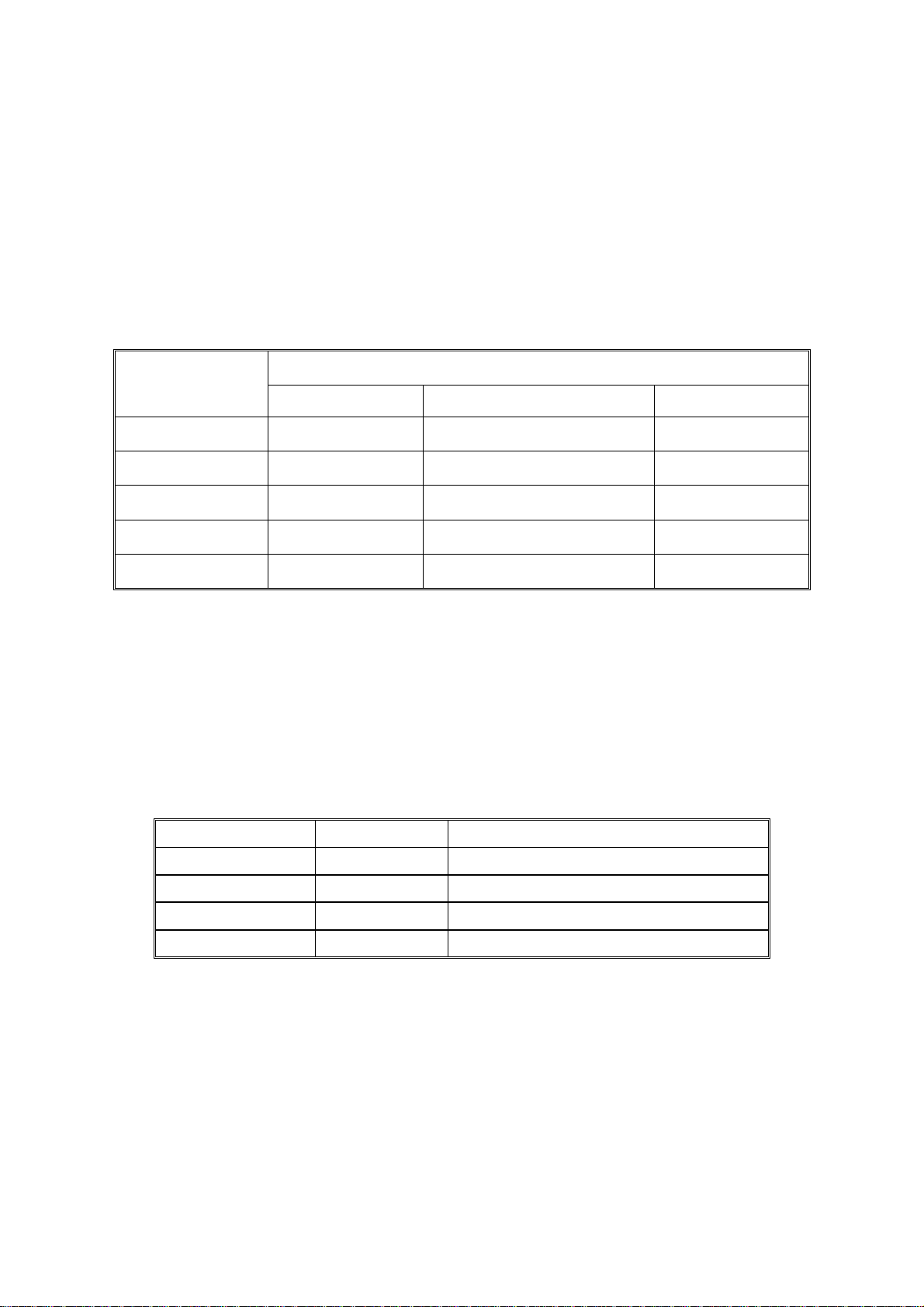
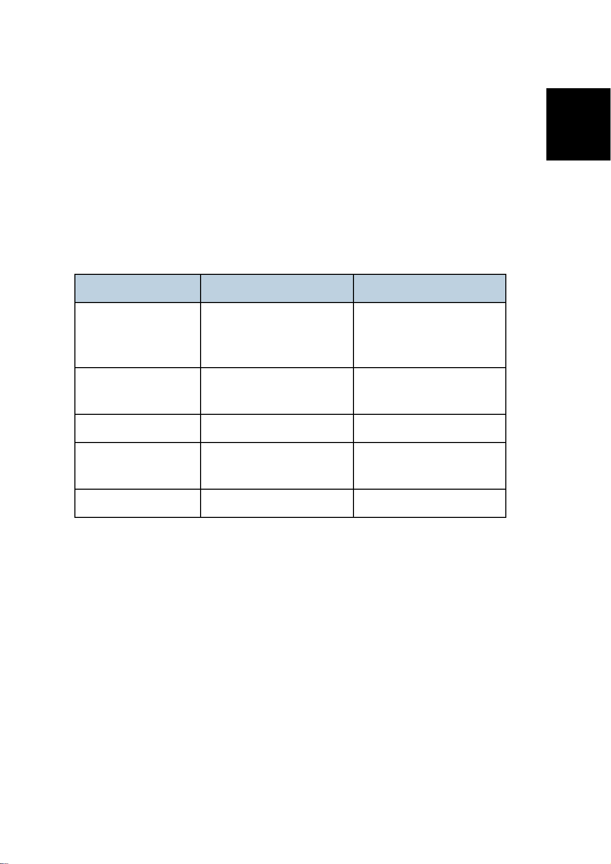
M095 SPC240DN Aficio SPC240DN SPC240DN
M096 SPC242DN Aficio SPC242DN SPC242DN
M099 SPC240SF Aficio SPC240SF SPC240SF
M100 SPC242SF Aficio SPC242SF SPC242SF
LANIER RICOH SAVIN
DOCUMENTATION HISTORY
REV. NO. DATE COMMENTS
*
11/2011 Original Printing
Page 6

Page 7

M095/M096/M099/M100
TABLE OF CONTENTS
1. PRODUCT INFORMATION .......................................................... 1-1
1.1GENERAL SPECIFICATIONS ................................................................... 1-1
1.2SUPPORTED PAPER SIZES .................................................................... 1-1
1.3MACHINE OVERVIEW .............................................................................. 1-2
1.3.1 COMPONENT LAYOUT ................................................................... 1-2
Engine (M095/M096) ............................................................................ 1-2
Engine (M099/M100) ............................................................................ 1-3
ADF (only for M099/M100) ................................................................... 1-4
Scanner (only for M099/M100) ............................................................. 1-4
1.3.2 PAPER PATH ................................................................................... 1-5
ADF (only for M099/M100) ................................................................... 1-5
1.3.3 DRIVE LAYOUT ............................................................................... 1-6
1.4MACHINE CONFIGURATION ................................................................... 1-8
1.4.1 PRINTER MODEL (M095/M096) ...................................................... 1-8
1.4.2 MF MODEL (M099/M100) ................................................................. 1-8
1.5GUIDANCE FOR THOSE WHO ARE FAMILIAR WITH PREDECESSOR
PRODUCTS ..................................................................................................... 1-9
2. INSTALLATION ............................................................................ 2-1
2.1INSTALLATION REQUIREMENTS ............................................................ 2-1
2.1.1 ENVIRONMENT ............................................................................... 2-1
2.1.2 MACHINE LEVEL ............................................................................. 2-1
2.1.3 MACHINE SPACE REQUIREMENT ................................................. 2-2
Printer Model ........................................................................................ 2-2
MF Model ............................................................................................. 2-2
2.1.4 POWER REQUIREMENTS .............................................................. 2-3
2.1.5 INSTALLATION PROCEDURE ........................................................ 2-3
3. PREVENTIVE MAINTENANCE .................................................... 3-3
3.1PREVENTIVE MAINTENANCE ................................................................. 3-3
4. REPLACEMENT AND ADJUSTMENT ........................................ 4-1
4.1BEFORE YOU START ............................................................................... 4-1
4.1.1 GENERAL PRECAUTIONS .............................................................. 4-1
SM i M095/M096/M099/M100
Page 8

AIO ....................................................................................................... 4-1
Laser Unit ............................................................................................. 4-2
Transfer Roller ..................................................................................... 4-2
Fusing .................................................................................................. 4-2
Paper Feed .......................................................................................... 4-2
Scanner Unit (for M099/M100) ............................................................. 4-2
4.1.2 RELEASING PLASTIC LATCHES .................................................... 4-3
4.1.3 AFTER SERVICING THE MACHINE ................................................ 4-3
4.1.4 LITHIUM BATTERIES (MF MODELS) .............................................. 4-3
4.2SPECIAL TOOLS ....................................................................................... 4-4
4.3EXTERIOR COVERS ................................................................................ 4-5
4.3.1 REAR COVER .................................................................................. 4-5
4.3.2 OPERATION PANEL ........................................................................ 4-6
4.3.3 RIGHT COVER ................................................................................. 4-7
4.3.4 LEFT COVER ................................................................................... 4-8
4.3.5 FRONT COVER UNIT ...................................................................... 4-9
4.4LASER OPTICS ....................................................................................... 4-10
4.4.1 CAUTION DECAL LOCATIONS ..................................................... 4-10
4.4.2 LASER OPTICS HOUSING UNIT ................................................... 4-11
After replacing the laser optics housing unit ....................................... 4-14
Printing out the test chart to make sure MUSIC was performed correctly4-14
Checking that MUSIC was Performed Correctly ................................ 4-16
If MUSIC has not been performed successfully ................................. 4-17
4.5AIO CARTRIDGE ..................................................................................... 4-18
4.5.1 AIO CARTRIDGE (ALL IN ONE CARTRIDGE) .............................. 4-18
4.5.2 BLACK AIO MOTOR ....................................................................... 4-19
4.5.3 COLOR AIO MOTOR ...................................................................... 4-22
4.6IMAGE TRANSFER ................................................................................. 4-23
4.6.1 IMAGE TRANSFER BELT UNIT ..................................................... 4-23
After replacing the image transfer belt unit ......................................... 4-24
4.6.2 ITB (IMAGE TRANSFER BELT) CLEANING UNIT......................... 4-25
4.6.3 AGITATOR MOTOR ....................................................................... 4-26
4.6.4 ITB (IMAGE TRANSFER BELT) CONTACT MOTOR ..................... 4-28
4.6.5 ITB (IMAGE TRANSFER BELT) CONTACT SENSOR ................... 4-29
4.6.6 TM (TONER MARK) SENSOR BASE ............................................. 4-30
4.6.7 WASTE TONER BOTTLE SET SENSOR ....................................... 4-31
4.6.8 WASTE TONER OVERFLOW SENSOR ........................................ 4-32
4.7PAPER TRANSFER ................................................................................ 4-33
M095/M096/M099/M100 ii SM
Page 9

4.7.1 TRANSFER UNIT ........................................................................... 4-33
4.7.2 TRANSFER ROLLER ..................................................................... 4-34
4.7.3 REGISTRATION ROLLER .............................................................. 4-36
Reassembling the registration roller unit ............................................ 4-36
4.7.4 REGISTRATION SENSOR ............................................................. 4-37
4.7.5 REGISTRATION CLUTCH ............................................................. 4-38
4.8IMAGE FUSING ....................................................................................... 4-39
4.8.1 FUSING UNIT ................................................................................. 4-39
4.8.2 FUSING LAMP ............................................................................... 4-41
When Reinstalling the Fusing Lamp ................................................... 4-43
When Reassembling the Fusing Unit ................................................. 4-44
4.8.3 TRANSPORT/FUSING MOTOR ..................................................... 4-45
4.9PAPER FEED .......................................................................................... 4-47
4.9.1 PAPER FEED CLUTCH .................................................................. 4-47
4.9.2 PAPER FEED ROLLER .................................................................. 4-48
4.9.3 SEPARATION PAD ........................................................................ 4-49
4.9.4 PAPER END SENSOR ................................................................... 4-50
4.10 PAPER EXIT ...................................................................................... 4-51
4.10.1 PAPER EXIT ROLLER ............................................................... 4-51
4.10.2 PAPER EXIT SENSOR .............................................................. 4-53
4.11 ELECTRICAL COMPONENTS .......................................................... 4-54
4.11.1 CONTROLLER BOARD ............................................................. 4-54
GDI/ PCL Controller Board (Printer Models) ...................................... 4-54
Controller Board (MF Models) ............................................................ 4-56
4.11.2 EGB (ENGINE BOARD) ............................................................. 4-58
Printer Models .................................................................................... 4-58
MF Models ......................................................................................... 4-60
4.11.3 FCU (ONLY FOR MF MODELS) ................................................ 4-62
4.11.4 INTERLOCK SWITCHES ........................................................... 4-63
4.11.5 FUSING FAN MOTOR ................................................................ 4-64
4.11.6 FUSING STRIPPER PAWL SOLENOID ..................................... 4-65
4.11.7 FUSING PRESSURE RELEASE SENSOR ................................ 4-67
4.11.8 LSU FAN MOTOR ...................................................................... 4-68
4.11.9 ID CHIP BOARD ......................................................................... 4-69
4.11.10 PSU .......................................................................................... 4-70
Fuse ................................................................................................... 4-73
4.11.11 HIGH VOLTAGE POWER SUPPLY BOARD ............................ 4-73
4.11.12 TEMPERATURE/HUMIDITY SENSOR .................................... 4-74
SM iii M095/M096/M099/M100
Page 10

4.11.13 DUPLEX MOTOR ..................................................................... 4-74
4.11.14 SPEAKER (ONLY FOR MF MODELS) ..................................... 4-76
4.11.15 EEPROM .................................................................................. 4-77
Checking that MUSIC was Performed Correctly ................................ 4-78
4.12 ADF (ONLY FOR MF MODELS) ........................................................ 4-79
4.12.1 ADF UNIT ................................................................................... 4-79
4.12.2 ORIGINAL TRAY ........................................................................ 4-80
4.12.3 ADF FEED UNIT ......................................................................... 4-81
4.12.4 ADF SEPARATION PAD ............................................................ 4-81
4.12.5 ADF FRONT COVER ................................................................. 4-82
4.12.6 ADF REAR COVER .................................................................... 4-82
4.12.7 ADF COVER ............................................................................... 4-83
4.12.8 ADF MOTOR .............................................................................. 4-84
4.12.9 ORIGINAL SET SENSOR........................................................... 4-86
4.12.10 ADF COVER OPEN SENSOR .................................................. 4-87
4.12.11 ADF FEED SENSOR ................................................................ 4-88
4.12.12 ADF DRIVE BOARD ................................................................. 4-89
4.13 SCANNER (ONLY FOR MF MODELS) .............................................. 4-90
4.13.1 SCANNER UNIT ......................................................................... 4-90
4.13.2 SCANNER TOP COVER ............................................................ 4-92
4.13.3 SCANNER CARRIAGE UNIT ..................................................... 4-93
4.13.4 EXPOSURE LAMP ..................................................................... 4-95
When reinstalling the exposure lamp ................................................. 4-96
4.13.5 LAMP STABILIZER BOARD ....................................................... 4-96
4.13.6 SCANNER MOTOR .................................................................... 4-97
5. SYSTEM MAINTENANCE REFERENCE ..................................... 5-1
5.1IMAGE PROBLEMS .................................................................................. 5-1
5.1.1 OVERVIEW ...................................................................................... 5-1
5.1.2 IMAGE PROBLEM ............................................................................ 5-1
5.2ERROR CODES ........................................................................................ 5-2
5.2.1 OVERVIEW ...................................................................................... 5-2
5.2.2 ERROR CODES LIST ....................................................................... 5-2
5.3SERVICE CALL CONDITIONS .................................................................. 5-6
5.3.1 SUMMARY ....................................................................................... 5-6
5.3.2 ENGINE SC ...................................................................................... 5-7
SC 1xx (Other Error) ............................................................................ 5-7
SC 2xx (Laser Optics Error) ................................................................. 5-8
SC 3xx (Charge Error) ........................................................................ 5-10
M095/M096/M099/M100 iv SM
Page 11

SC 4xx (Image Transfer and Transfer Error) ...................................... 5-11
SC 5xx (Motor and Fusing Error) ....................................................... 5-13
SC 6xx (Communication and Other Error) .......................................... 5-18
5.3.3 CONTROLLER SC ......................................................................... 5-19
SC8xx ................................................................................................. 5-19
5.4SERVICE MENU ...................................................................................... 5-21
5.4.1 OVERVIEW .................................................................................... 5-21
5.4.2 MAINTENANCE MODE MENU ...................................................... 5-22
Menu List ............................................................................................ 5-22
5.4.3 FAX SERVICE TEST MENU (ONLY FOR MF MODELS) ............... 5-35
Entering the Fax Service Test Menu .................................................. 5-35
Selecting an Item ............................................................................... 5-35
Going into the Next Level/ Returning to the Previous Level ............... 5-35
Exiting the Maintenance Mode Menu ................................................. 5-35
Menu List ............................................................................................ 5-35
5.5CONFIGURATION, MAINTENANCE AND TEST PAGE INFORMATION 5-37
5.5.1 OVERVIEW .................................................................................... 5-37
To Print the Configuration Page from the Machine (Printer models) .. 5-37
To Print the Test Page from the Machine (only for Printer Models) .... 5-37
To Print the Maintenance Page (Printer models) ............................... 5-37
To Print the Configuration Page/ Maintenance Page (MF models) .... 5-38
5.5.2 ERROR LOG .................................................................................. 5-38
5.5.3 COUNTER AND COVERAGE (ONLY FOR PRINTER MODELS) .. 5-39
Configuration Page ............................................................................ 5-39
5.6FIRMWARE UPDATING .......................................................................... 5-40
5.6.1 CHECKING THE MACHINE FIRMWARE VERSION ...................... 5-40
5.6.2 UPDATING THE CONTROLLER FIRMWARE ............................... 5-40
5.6.3 UPDATING THE ENGINE FIRMWARE .......................................... 5-42
5.6.4 BOOT LOADER FIRMWARE ......................................................... 5-43
6. ENVIRONMENTAL CONSERVATION ......................................... 6-1
6.1ENERGY SAVING ..................................................................................... 6-1
6.1.1 ENERGY SAVER MODES ............................................................... 6-1
Timer Settings (Printer Models) ............................................................ 6-2
Timer Settings (MF Models) ................................................................. 6-2
Return to Stand-by Mode ..................................................................... 6-2
Recommendation ................................................................................. 6-3
6.2PAPER SAVE ............................................................................................ 6-4
6.2.1 EFFECTIVENESS OF DUPLEX/COMBINE FUNCTION .................. 6-4
SM v M095/M096/M099/M100
Page 12

1. Duplex .............................................................................................. 6-4
2. Combine mode ................................................................................. 6-4
3. Duplex + Combine ............................................................................ 6-5
M095/M096/M099/M100 SERVICE MANUAL APPENDICES
SEE M095/M096/M099/M100 SERVICE MANUAL APPENDICES SECTION FOR DETAILED
TABLE OF CONTENTS
PAPER FEED UNIT TYPE TK1010 (G849)
SEE SECTION G849 FOR DETAILED TABLE OF CONTENTS
M095/M096/M099/M100 vi SM
Page 13

READ THIS FIRST
Safety Notices
Important Safety Notices
Prevention of Physical Injury
1. Before disassembling or assembling parts of the machine and peripherals, make sure that
the machine power cord is unplugged.
2. The wall outlet should be near the machine and easily accessible.
3. If any adjustment or operation check has to be made with exterior covers off or open while
the main switch is turned on, keep hands away from electrified or mechanically driven
components.
4. The machine drives some of its components when it completes the warm-up period. Be
careful to keep hands away from the mechanical and electrical components as the machine
starts operation.
5. The inside and the metal parts of the fusing unit become extremely hot while the machine is
operating. Be careful to avoid touching those components with your bare hands.
Health Safety Conditions
Toner is non-toxic, but if you get either of them in your eyes by accident, it may cause temporary
eye discomfort. Try to remove with eye drops or flush with water as first aid. If unsuccessful, get
medical attention.
Observance of Electrical Safety Standards
The machine and its peripherals must be serviced by a customer service representative who
has completed the training course on those models.
Safety and Ecological Notes for Disposal
1. Do not incinerate toner bottles or used toner. Toner dust may ignite suddenly when
exposed to an open flame.
2. Dispose of used toner, the maintenance unit which includes developer or the organic
photoconductor in accordance with local regulations. (These are non-toxic supplies.)
3. Dispose of replaced parts in accordance with local regulations.
Page 14
To prevent a fire or explosion, keep the machine away from flammable liquids, gases,
and aerosols. A fire or an explosion might occur.
The Controller board on the MF model contains a lithium battery. The danger of
explosion exists if a battery of this type is incorrectly replaced. Replace only with the
same or an equivalent type recommended by the manufacturer. Discard batteries in
accordance with the manufacturer's instructions and local regulations.
Laser Safety
The Center for Devices and Radiological Health (CDRH) prohibits the repair of laser-based
optical units in the field. The optical housing unit can only be repaired in a factory or at a
location with the requisite equipment. The laser subsystem is replaceable in the field by a
qualified Customer Engineer. The laser chassis is not repairable in the field. Customer
engineers are therefore directed to return all chassis and laser subsystems to the factory or
service depot when replacement of the optical subsystem is required.
Use of controls, or adjustment, or performance of procedures other than those
specified in this manual may result in hazardous radiation exposure.
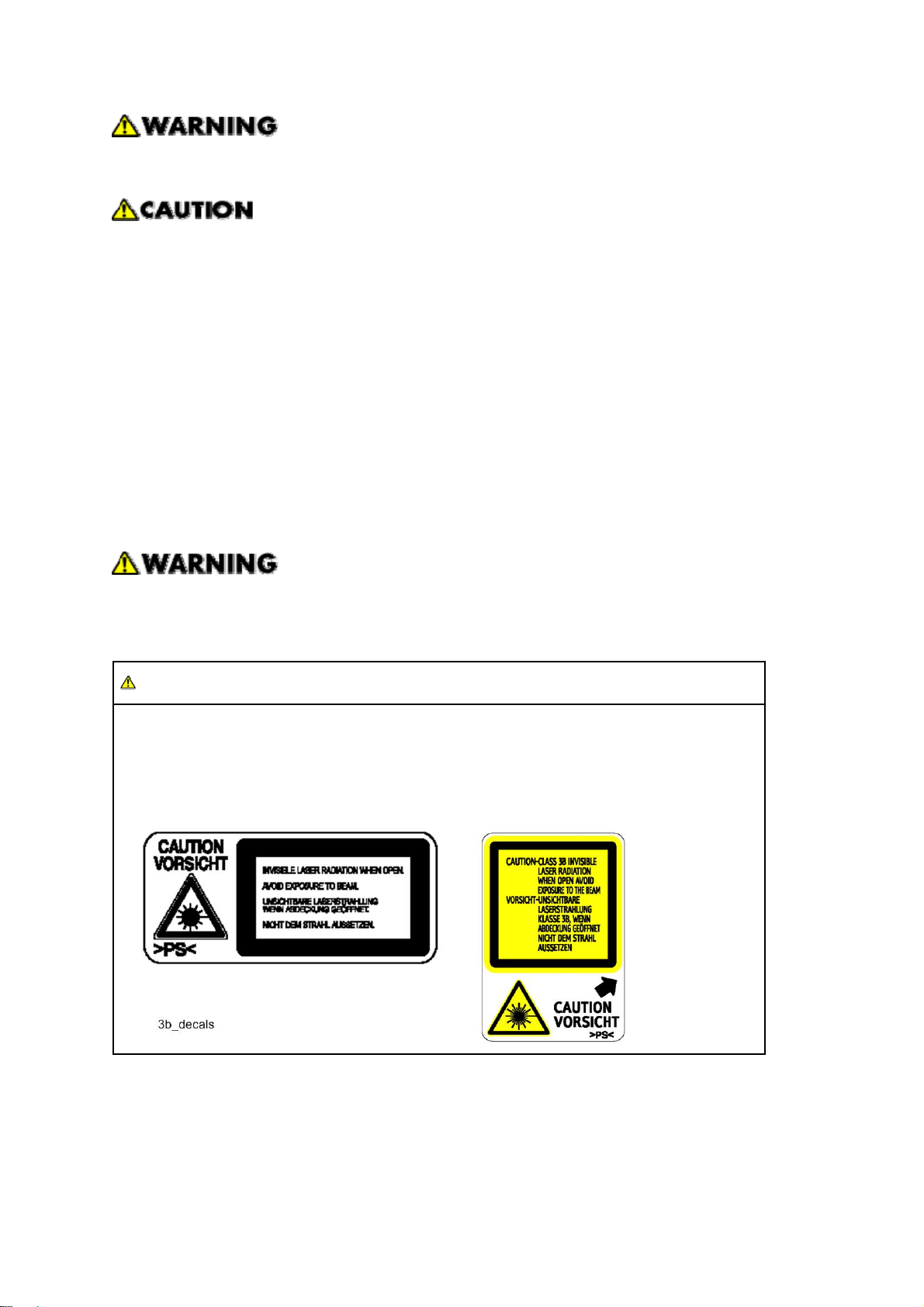
WARNING
WARNING:
Turn off the main switch before attempting any of the procedures in the Laser Optics
Housing Unit section. Laser beams can seriously damage your eyes.
CAUTION MARKING:
Page 15
Symbols, Abbreviations and Trademarks
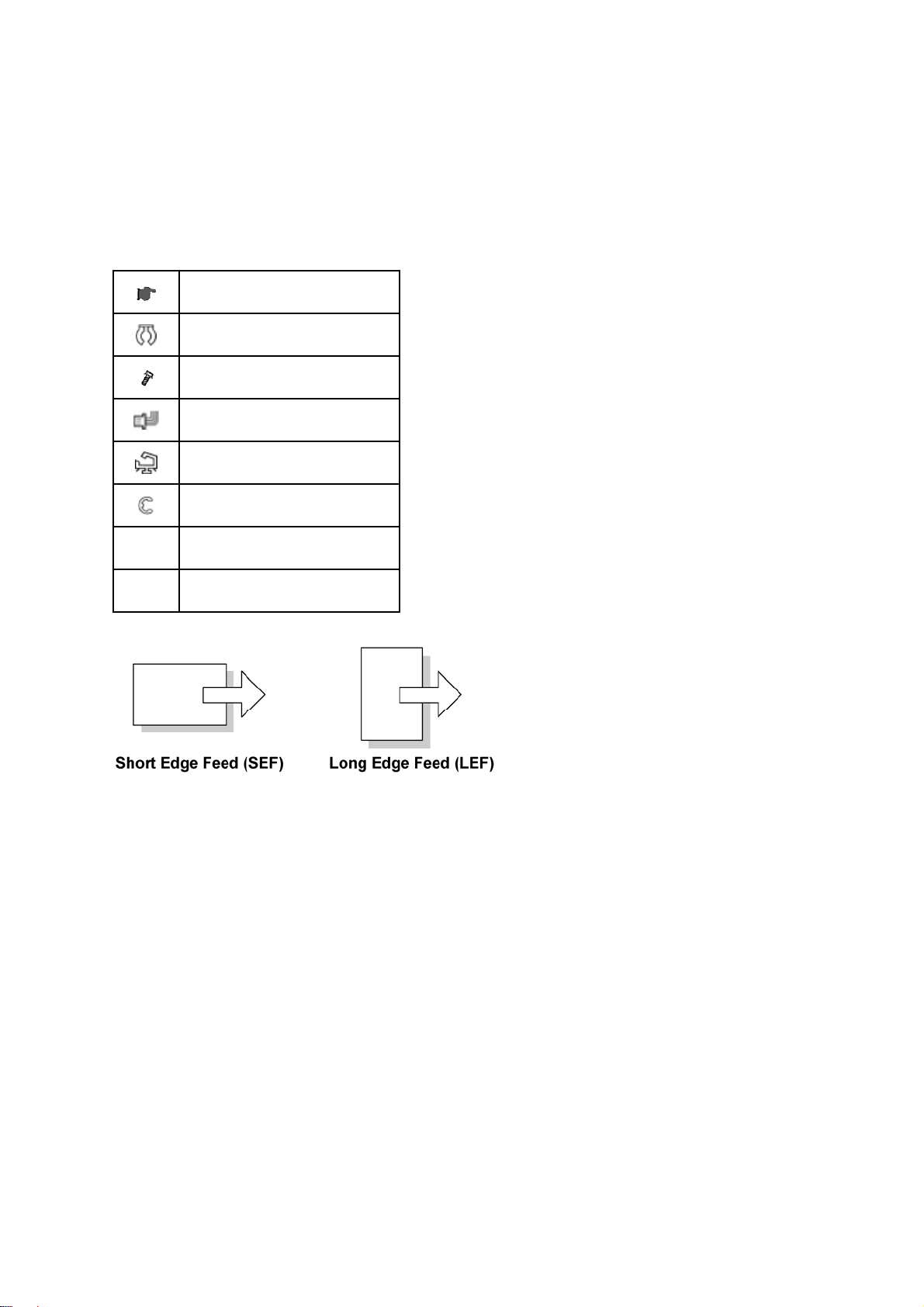
This manual uses several symbols and abbreviations. The meaning of those symbols and
abbreviations are as follows:
See or Refer to
Clip ring
Screw
Connector
Clamp
E-ring
SEF Short Edge Feed
LEF Long Edge Feed
Trademarks
Microsoft®, Windows®, and MS-DOS® are registered trademarks of Microsoft Corporation in the
United States and /or other countries.
PostScript
PCL
Ethernet
PowerPC
®
is a registered trademark of Adobe Systems, Incorporated.
®
is a registered trademark of Hewlett-Packard Company.
®
is a registered trademark of Xerox Corporation.
®
is a registered trademark of International Business Machines Corporation.
Other product names used herein are for identification purposes only and may be trademarks of
their respective companies. We disclaim any and all rights involved with those marks.
Page 16

Page 17

PRODUCT INFORMATION
REVISION HISTORY
Page Date Added/Updated/New
None
Page 18

Page 19

1. PRODUCT INFORMATION
General Specifications
1.1 GENERAL SPECIFICATIONS
See Appendices:
Appendices: Basic Specifications
Appendices: Controller Specifications
1.2 SUPPORTED PAPER SIZES
See Appendices:
Appendices: Supported Paper Sizes
Product
Information
SM 1-1 M095/M096/M099/M100
Page 20
Machine Overview
1.3 MACHINE OVERVIEW
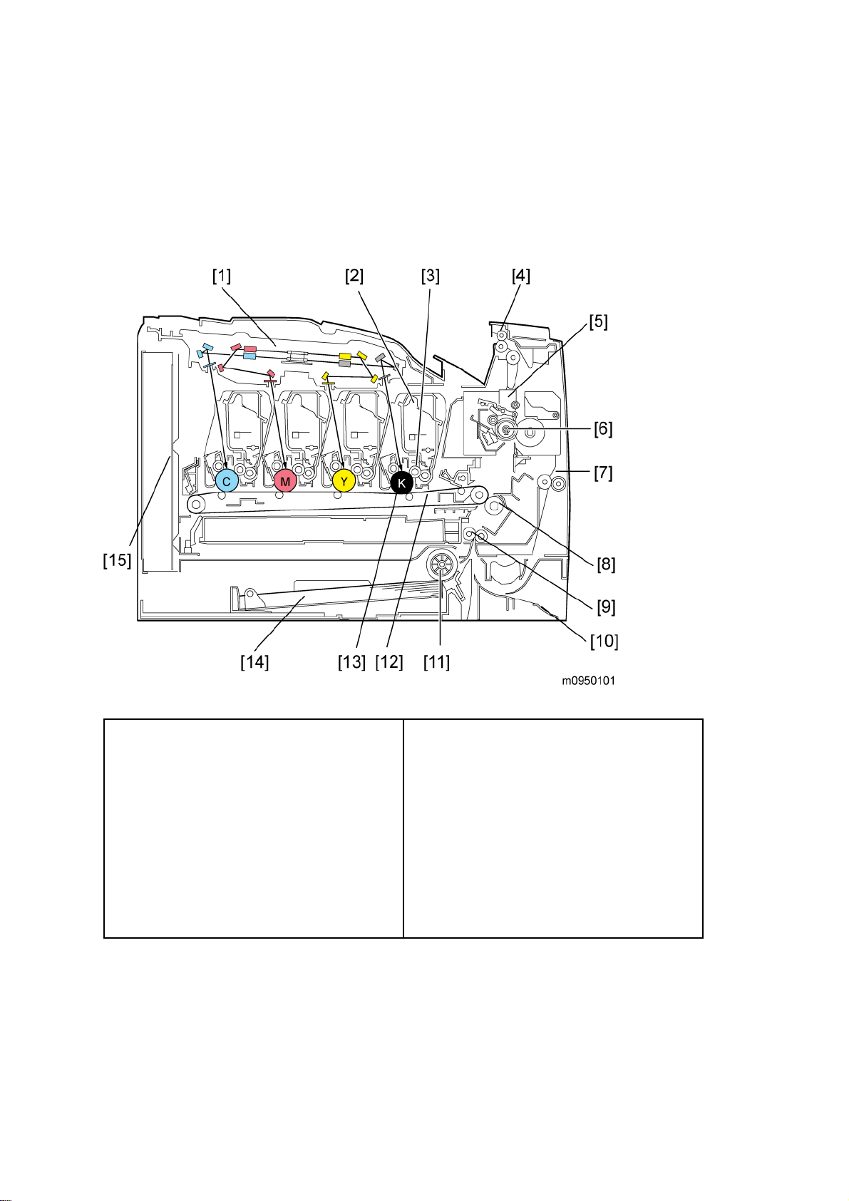
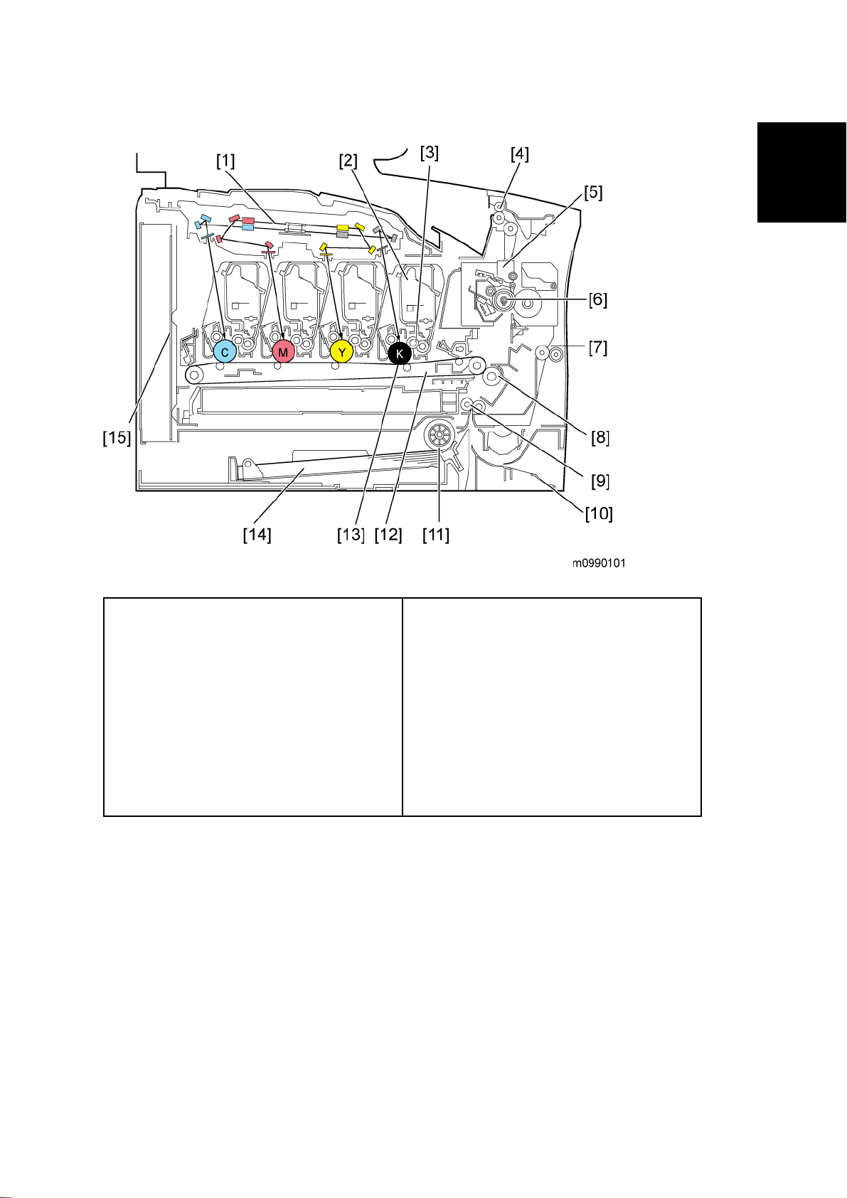
1.3.1 COMPONENT LAYOUT
Engine (M095/M096)
1. Laser Optics Housing Unit
2. Print Cartridge (AIO)
3. Development Roller (AIO)
4. Paper Exit
5. Fusing Unit
6. Fusing Lamp
7. Duplex Path
8. Transfer Roller
9. Registration Roller
10. By-pass
11. Paper Feed Roller
12. ITB (Image Transfer Belt) Unit
13. OPC (AIO)
14. Tray 1
15 EGB/Controller
M095/M096/M099/M100 1-2 SM
Page 21
Engine (M099/M100)
Machine Overview
Product
Information
1. Laser Optics Housing Unit
2. Print Cartridge (AIO)
3. Development Roller (AIO)
4. Paper Exit
5. Fusing Unit
6. Fusing Lamp
7. Duplex Path
8. Transfer Roller
9. Registration Roller
10. By-pass
11. Paper Feed Roller
12. ITB (Image Transfer Belt) Unit
13. OPC (AIO)
14. Tray 1
15 EGB/Controller
SM 1-3 M095/M096/M099/M100
Page 22
Machine Overview
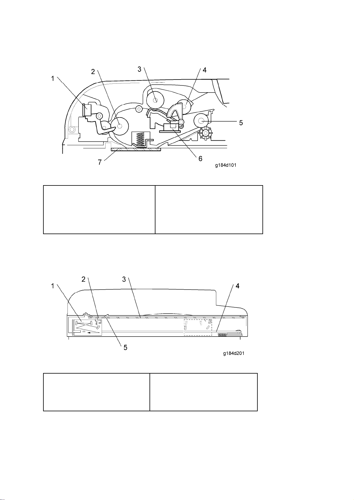
ADF (only for M099/M100)
1. Feed Sensor
2. Feed Roller
3. Separation Roller
4. Pick-up Roller
Scanner (only for M099/M100)
5. Exit Roller
6. Original Set Sensor
7. DF Exposure Glass
1. Scanner Carriage Unit
2. DF Exposure Glass
3. Exposure Glass
M095/M096/M099/M100 1-4 SM
4. Carriage Drive Bar
5. White Plate
Page 23
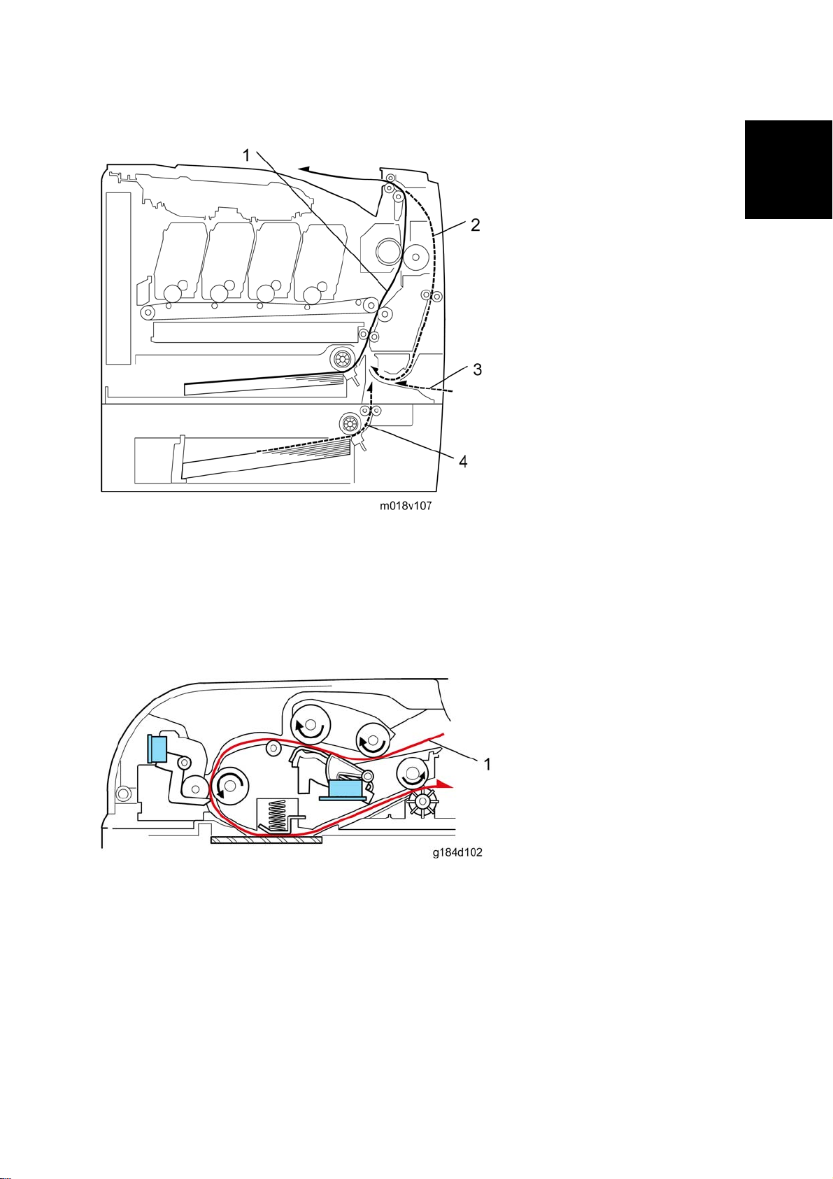
1.3.2 PAPER PATH
Machine Overview
Product
Information
1. Paper path from tray 1
2. Duplex path
3. By-pass tray
4. Paper path from tray 2 (optional)
ADF (only for M099/M100)
1. Original path
SM 1-5 M095/M096/M099/M100
Page 24
Machine Overview
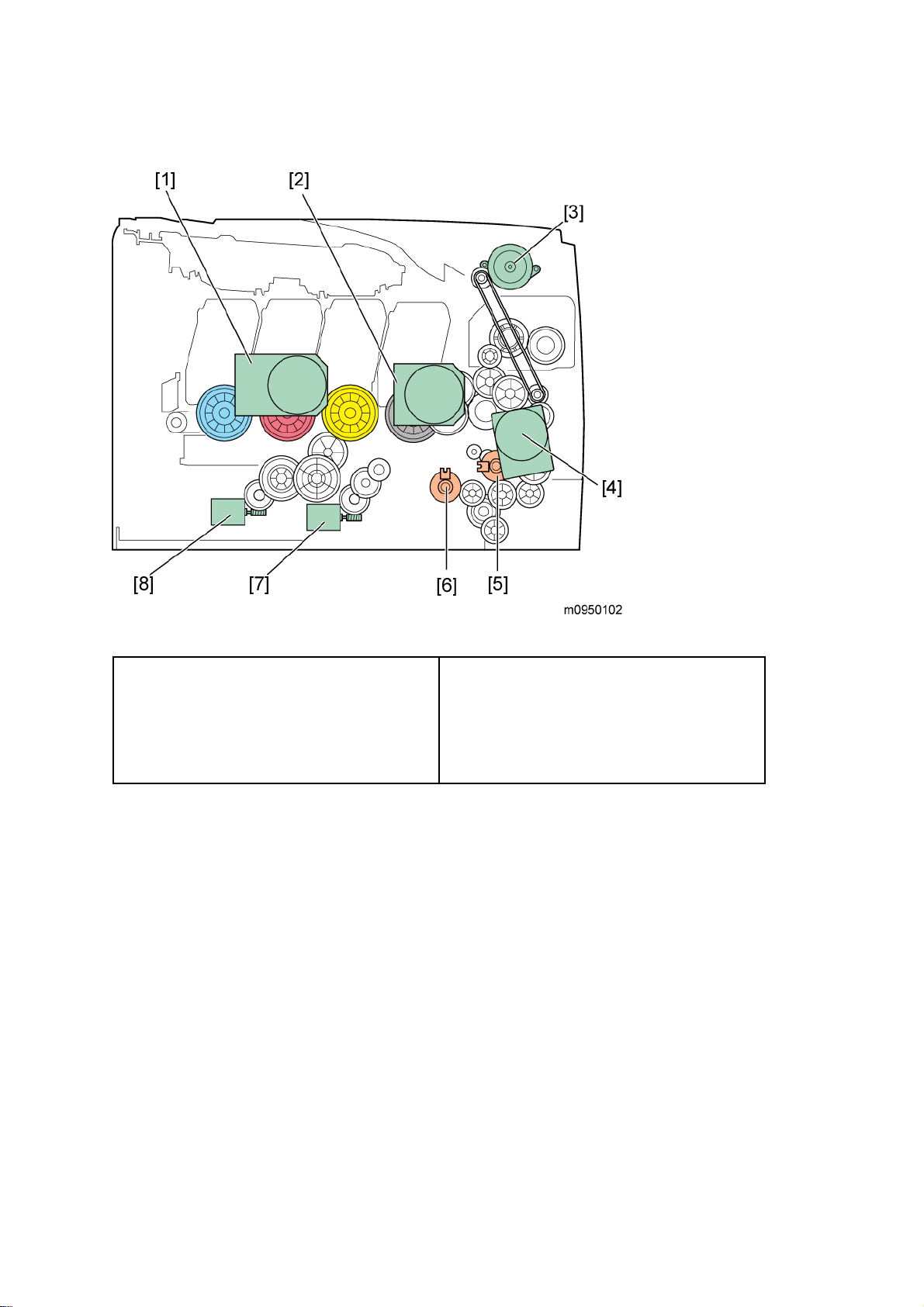
1.3.3 DRIVE LAYOUT
1. Color AIO Motor
2. Black AIO Motor
3. Duplex Motor
4. Transport/Fusing Motor
Color AIO Motor:
This drives the color AIOs (Cyan, Magenta and Yellow)
Black AIO Motor:
This drives the black AIO and the ITB (Image Transfer Belt).
Duplex Motor :
This drives the paper exit roller and the duplex roller.
Transport/Fusing Motor:
This drives the fusing unit, paper feed roller, registration roller and paper exit roller via the
paper feed clutch, registration clutch and gears.
5. Registration Clutch
6. Paper Feed Clutch
7. Agitator Motor
8. ITB (Image Transfer Belt) Contact Motor
Registration Clutch:
This transfers drive from the transport/ fusing motor to the registration roller.
Paper Feed Clutch:
This transfers drive from the transport/ fusing motor to the paper feed roller.
M095/M096/M099/M100 1-6 SM
Page 25

Agitator Motor:
This moves the agitators in the waste toner bottle.
ITB Contact Motor:
Machine Overview
This moves the ITB into contact with and away from the color OPCs.
Product
Information
SM 1-7 M095/M096/M099/M100
Page 26

Machine Configuration
1.4 MACHINE CONFIGURATION
1.4.1 PRINTER MODEL (M095/M096)
Models
Duplex
Unit
PE-P2a (M095) Auto N 500 x 1 Y N
PE-P2c (M096) Auto N 500 x 1 N Y
Optional
Memory
Optional
Tray (G849)
DDST
(GDI)
1.4.2 MF MODEL (M099/M100)
Models
Duplex
Unit
PE-MF3a (M099) Auto N 500 x 1 Y N Y
PE-MF3c (M100) Auto N 500 x 1 N Y Y
Optional
Memory
Optional
Tray (G849)
DDST
(GDI)
PCL
PS
PCL
PS
Fax
M095/M096/M099/M100 1-8 SM
Page 27
Guidance for Those Who are Familiar with Predecessor Products
1.5 GUIDANCE FOR THOSE WHO ARE FAMILIAR WITH
PREDECESSOR PRODUCTS
The M095/M096 series models are similar to the M035/M036 series, and the M099/M100 series
models are similar to the M018/M019 series. If you have experience with those products, the
following information will be of help when you read this manual.
Different Points from Previous Products
Printer models:
New Fusing Unit that
improves maintenance
efficiency
Operation Panel 2-line LCD and 3 high visibility
Pictbridge Supported Not supported
Yes No
LED indicators
M095/M096 M035/M036
2-line LCD and standard LED
indicators
Product
Information
Smart Organizing
Monitor (SOM)
Warm-up Time 30 seconds 48 seconds
Not required Required
SM 1-9 M095/M096/M099/M100
Page 28

Guidance for Those Who are Familiar with Predecessor Products
MF models:
M099/M100 M018/M019
Front USB Connector Yes No
New Fusing Unit that
improves maintenance
Yes No
efficiency
Operation Panel 4-line LCD 2-line LCD
Pictbridge Supported Not supported
Warm-up Time 30 seconds 48 seconds
M095/M096/M099/M100 1-10 SM
Page 29

INSTALLATION
REVISION HISTORY
Page Date Added/Updated/New
None
Page 30

Page 31

2. INSTALLATION
2.1 INSTALLATION REQUIREMENTS
2.1.1 ENVIRONMENT
Installation Requirements
Installation
1. Temperature Range: 10°C to 32°C (50°F to 89.6°F)
2. Humidity Range: 15% to 80% RH
3. Ambient Illumination: Less than 2,000 lux (do not expose to direct sunlight)
4. Ventilation: 3 times/hr/person
5. Do not put the machine in areas that get sudden temperature changes. This includes:
Areas directly exposed to cool air from an air conditioner
Areas directly exposed to heat from a heater.
6. Do not put the machine in areas that get exposed to corrosive gas.
7. Do not install the machine at locations over 2,000 m (6,560 ft.) above sea level.
8. Put the machine on a strong, level base. (Inclination on any side must be no more than 5
mm.)
9. Do not put the machine in areas with strong vibrations.
2.1.2 MACHINE LEVEL
Front to back: Within 5 mm (0.2") of level
Right to left: Within 5 mm (0.2") of level
SM 2-1 M095/M096/M099/M100
Page 32

Installation Requirements
2.1.3 MACHINE SPACE REQUIREMENT
Put the machine near the power source with these clearances:
Printer Model
Left side: Over 20 cm (7.9")
Rear: Over 10 cm (4")
Right side: Over 10 cm (4")
Front: Over 70 cm (27.5")
MF Model
Left side: Over 20 cm (7.9")
Rear: Over 20 cm (7.9")
Right side: Over 10 cm (4")
Front: Over 70 cm (27.5")
Top: Over 24 cm (9.5")
M095/M096/M099/M100 2-2 SM
Page 33

2.1.4 POWER REQUIREMENTS
Make sure that the plug is tightly in the outlet.
Avoid multi-wiring.
Make sure that you ground the machine.
120 V, 60 Hz: More than 11 A (for North America)
Installation Requirements
Input voltage level
Permitted voltage fluctuation: 10%
Do not set anything on the power cord.
220 V to 240 V, 50 Hz/60 Hz: More than 6 A (for Europe/ Asia)
110 V, 60 Hz: More than 12 A (for Taiwan)
2.1.5 INSTALLATION PROCEDURE
Refer to the Quick Installation Guide for details about installing the machine.
Installation
SM 2-3 M095/M096/M099/M100
Page 34

Page 35

PREVENTIVE MAINTENANCE
REVISION HISTORY
Page Date Added/Updated/New
None
Page 36

Page 37

3. PREVENTIVE MAINTENANCE
3.1 PREVENTIVE MAINTENANCE
See "Appendices" for the "User Replaceable Items".
Preventive Maintenance
Preventive
Maintenance
SM 3-3 M095/M096/M099/M100
Page 38

Page 39

REPLACEMENT AND ADJUSTMENT
REVISION HISTORY
Page Date Added/Updated/New
None
Page 40

Page 41

Before You Start
4. REPLACEMENT AND ADJUSTMENT
4.1 BEFORE YOU START
4.1.1 GENERAL PRECAUTIONS
If there are printer jobs in the machine, print out all jobs in the printer buffer.
Turn off the main power switch and unplug the machine before you do the procedures
in this section.
Use extreme caution when removing and replacing components. The cables in the machine are
located very close to moving parts; proper routing is a must.
After components have been removed, any cables that have been displaced during the
procedure must be restored as close as possible to their original positions. Before removing any
component from the machine, note any cable routings that may be affected.
Before servicing the machine:
1. Verify that documents are not stored in memory.
2. Remove the print cartridge before you remove parts.
3. Unplug the power cord.
4. Work on a flat and clean surface.
5. Replace with authorized components only.
6. Do not force plastic material components.
Make sure all components are returned to their original positions.
AIO
The AIO consists of the OPC drum, charge roller, development unit, cleaning components and
toner tank. Observe the following precautions when handling the AIO.
1. Never touch the drum surface with bare hands. If the drum surface is dirty or if you have
accidentally touched it, wipe it with a dry cloth, or clean it with wet cotton and then wipe it
dry with a cloth.
2. Never use alcohol to clean the drum. Alcohol will dissolve the drum surface.
Replacement
and
Adjustment
3. Store the AIO in a cool dry place.
4. Do not expose the drum to corrosive gases (ammonia, etc.).
5. Do not shake a used AIO, as this may cause toner to spill out.
6. Dispose of used AIO components in accordance with local regulations.
SM 4-1 M095/M096/M099/M100
Page 42

Before You Start
Laser Unit
1. Do not loosen or adjust the screws securing the LD drive board on the LD unit. Doing so will
throw the LD unit out of adjustment.
2. Do not adjust the variable resistors on the LD unit, as these are permanently adjusted at
the factory. If replacement of the LD drive board is necessary, replace the entire LD unit.
3. Keep the polygon mirror and toroidal lens free of dust. Laser performance is very sensitive
to dust on these components.
4. Do not touch the shield glass or the surface of the polygon mirror with bare hands.
5. Do not adjust the Laser Synchronization detector on the LD unit, as these are permanently
adjusted at the factory.
Transfer Roller
1. Never touch the surface of the transfer roller with bare hands.
2. Be careful not to scratch the transfer roller, as the surface is easily damaged.
Fusing
1. After installing the fusing thermistor, make sure that it is in contact with the hot roller and
that the roller can rotate freely.
2. Be careful to avoid damage to the hot roller stripper pawls and their tension springs.
3. Do not touch the fusing lamp and rollers with bare hands.
4. Make sure that the fusing lamp is positioned correctly and that it does not touch the inner
surface of the hot roller.
Paper Feed
1. Do not touch the surface of paper feed rollers.
2. To avoid misfeeds, the side and end fences in each paper tray must be positioned correctly
so as to align with loaded paper size.
Scanner Unit (for M099/M100)
1. Use alcohol or glass cleaner to clean the exposure and scanning glass. This will reduce the
static charge on the glass.
2. Use a blower brush or a water-moistened cotton pad to clean the mirrors and lenses.
3. Make sure to not bend or crease the exposure lamp’s ribbon cable.
4. Do not disassemble the lens unit. This will cause the lens and copy image to get out of
focus.
5. Do not turn any of the LED positioning screws. This will put the LED out of position.
M095/M096/M099/M100 4-2 SM
Page 43

Before You Start
4.1.2 RELEASING PLASTIC LATCHES
Many of the parts are held in place with plastic latches. The latches break easily, so release
them carefully. To release a latch, press the hook end of the latch away from the part to which it
is latched.
4.1.3 AFTER SERVICING THE MACHINE
1. Make sure all parts that require grounding are properly grounded.
2. Make sure the interlock switch is functioning.
3. Do not leave unused solder or parts inside the machine.
4. Do not leave any tools inside the machine.
5. Make sure all wires are properly connected and routed.
6. Make sure wires are not jammed between parts of the machine.
4.1.4 LITHIUM BATTERIES (MF MODELS)
Incorrect replacement of lithium battery(s) on the controller or on the fax unit poses risk
of explosion. Replace only with the same type or with an equivalent type recommended
by the manufacturer. Discard used batteries in accordance with the manufacturer’s
instructions.
Replacement
and
Adjustment
SM 4-3 M095/M096/M099/M100
Page 44

Special Tools
4.2 SPECIAL TOOLS
PC: Windows 2000/XP/Vista/7 or Windows Server 2003/2003 R2.
USB cable or Crossover cable
M095/M096/M099/M100 4-4 SM
Page 45

Exterior Covers
4.3 EXTERIOR COVERS
Turn off the main power switch and unplug the printer before you do the procedures in
this section.
4.3.1 REAR COVER
1: MF models
2: Printer models
1. Rear tray cover [A]
1: MF Models
2: Printer Models
2. Only for Printers: Interface cover [C] (hook x 1)
Replacement
and
Adjustment
3. Rear cover [B] (MF:
The screw in the Interface cover: M3 x 8, others: M4 x 10
SM 4-5 M095/M096/M099/M100
x 2 Printer: x 3)
Page 46

Exterior Covers
4.3.2 OPERATION PANEL
1: MF Models
2: Printer Models
1. Open the top cover [A].
1: MF Models
2: Printer Models
2. Open the front cover [B].
3. Front harness cover [C] (
1: MF Models
2: Printer Models
4. Operation panel [D] (
x 1, x 1)
x 1)
M095/M096/M099/M100 4-6 SM
Page 47

4.3.3 RIGHT COVER
1. Rear cover ( p.4-5)
Exterior Covers
2. Operation panel (
3. Right cover [A] (
Top front screw: M3 x 8, others: M4 x 10
p.4-6)
x 4)
and
Adjustment
Replacement
SM 4-7 M095/M096/M099/M100
Page 48

Exterior Covers
4.3.4 LEFT COVER
1. Open the front cover.
2. Open the top cover.
3. Left cover [A] (
Top front screw: M3 x 8, others: M4 x 10
Remove the rear panel and the operation panel in advance when you meet
difficulties in removing the left cover.
x 3, hook at the arrow mark above)
M095/M096/M099/M100 4-8 SM
Page 49

4.3.5 FRONT COVER UNIT
1. Rear cover ( p.4-5)
Exterior Covers
2. Operation panel (
3. Transfer unit (
4. Right cover (
5. Cover link gear unit [A] (
p.4-6)
p.4-33)
p.4-7)
x 2)
and
Adjustment
Replacement
6. Release the belt [B]
7. Front cover unit [C] (
SM 4-9 M095/M096/M099/M100
x 4)
Page 50

Laser Optics
4.4 LASER OPTICS
Turn off the main power switch and unplug the printer before beginning any of the
procedures in this section. Laser beams can cause serious eye injury.
4.4.1 CAUTION DECAL LOCATIONS
Caution decals are attached as shown below.
Be sure to turn off the main power switch and disconnect the power plug from the
power outlet before beginning any disassembly or adjustment of the laser unit. This
printer uses a class IIIb laser beam with a wavelength of 655 nm and an output of 7
mW. The laser can cause serious eye injury.
M095/M096/M099/M100 4-10 SM
Page 51

4.4.2 LASER OPTICS HOUSING UNIT
1. Rear cover ( p.4-5)
Laser Optics
2. Controller box cover (
3. MF model only: Remove the controller bracket (
4. Disconnect the three harnesses from CN301, 302 and 303 on the EGB (
p.4-54)
p.4-58)
x 3).
Replacement
and
Adjustment
5. Open the top cover [A].
SM 4-11 M095/M096/M099/M100
Page 52

Laser Optics
6. Lift up the hook [B] of the harness guide at the rear-left frame and slide the harness guide to
the right.
7. Stoppers [C] (
x 2 each; left side and right side)
8. Remove the springs [D] (left side and right side).
9. Remove the laser optics housing unit [E] from the top cover and place it on the main body.
Always use two hands when carrying the laser optics housing unit. Be sure not to
drop the laser optics housing unit.
M095/M096/M099/M100 4-12 SM
Page 53

10. Take out the harnesses [F] (
Laser Optics
x 1).
11. Remove the laser optics housing unit.
and
Adjustment
Replacement
SM 4-13 M095/M096/M099/M100
Page 54

Laser Optics
After replacing the laser optics housing unit
1. Open the front cover and turn on the machine.
Do the following 2 steps with the front cover of the machine open.
On the LCD, access “LSU Adjustment” inside the “Engine Maintenance” menu.
Manually input the corresponding LSU data from your supervisor into the space
provided on the LCD.
2. Close the front cover.
3. Perform “Color Registration” in the “Engine Maintenance” menu.
4. Turn the power off and on.
MUSIC will be performed automatically.
5. Print out the test chart (
successfully (see ‘Printing out the Test Chart” and ‘Checking that MUSIC was Performed
Correctly’ below).
6. If necessary, adjust the registration settings for each tray and for the front and rear sides of
the paper with the "Engine Maintenance" menu.
When the MUSIC error persists, contact your supervisor, and get a set of LD
parameters for the unit. After that, enter them with “LSU Adjustment” in the
Maintenance Mode Menu (
below).
Test Chart), and make sure that MUSIC was performed
“If MUSIC has not been performed successfully”
Printing out the test chart to make sure MUSIC was performed correctly
M095/M096/M099/M100 4-14 SM
Page 55

1. Click the “Properties” tab inside the printer driver.
2. Click the “Print Quality” tab.
3. Select the “Manual” radio button.
4. Click [Advanced…].
Laser Optics
5. Select “Off” for the three Color Profile pull-down menus shown (i.e. for Text, Graphics, and
Photo modes).
6. Click [OK] twice to print out the test chart.
7. Make sure that MUSIC was performed successfully.
Replacement
and
Adjustment
SM 4-15 M095/M096/M099/M100
Page 56

Laser Optics
Checking that MUSIC was Performed Correctly
Four sets of vertical lines appear on the test chart (C and k, M and k, Y and k…). In each set,
look for vertical lines that are aligned within the region defined by “OK”.
If all sets have at least one set of vertical lines that are aligned MUSIC was successful.
M095/M096/M099/M100 4-16 SM
Page 57

If MUSIC has not been performed successfully
Laser Optics
1. Open the upper cover and check the lot number of the laser optics housing unit.
2. Contact your supervisor, and get the LD parameters for this lot number [A].
3. Open the front cover and turn on the machine.
4. Program the settings for the laser optics housing unit.
On the LCD, access “LSU Adjustment” inside the “Engine Maintenance” menu.
Manually input the corresponding LSU data from your supervisor into the space
provided on the LCD.
5. Close the front cover.
6. Execute “Color Registration”, which is inside the “Engine Maintenance” menu.
7. Turn the main power Off and On.
MUSIC will be performed automatically.
8. If necessary, adjust the registration settings for each tray and for the front and rear sides of
the paper with the "Engine Maintenance" menu.
Replacement
and
Adjustment
SM 4-17 M095/M096/M099/M100
Page 58

AIO Cartridge
4.5 AIO CARTRIDGE
4.5.1 AIO CARTRIDGE (ALL IN ONE CARTRIDGE)
1. Open the top cover.
2. AIO cartridge [A]
M095/M096/M099/M100 4-18 SM
Page 59

AIO Cartridge
4.5.2 BLACK AIO MOTOR
1. Left cover ( p.4-8)
2. Disconnect the fusing connector [A] and remove the fusing relay harness [B] (hooks x 2).
3. Fusing harness guide [C] (
4. Fusing thermistor harness guide (
x 2)
p.4-74)
and
Adjustment
Replacement
5. Disconnect the connectors shown by arrows in the above picture and release all harnesses
on the harness guide [D].
6. Harness guide [D] (
SM 4-19 M095/M096/M099/M100
x 4, hook x 1)
Page 60

AIO Cartridge
7. Interlock switch base ( p.4-63)
8. FCU and Speaker bracket (
p.4-54)
9. Disconnect the connector (CN305) on the EGB.
10. LSU fan motor base [E] ( x 2, x 1)
11. Drive unit [F] (
M095/M096/M099/M100 4-20 SM
x 4)
Page 61

12. Drive unit guide [G] (
x 3)
13. Black AIO gear [H] (snap ring x 1)
14. ITB gear [I] (snap ring x 1)
AIO Cartridge
15. Black AIO motor [J] (
x 3)
and
Adjustment
Replacement
SM 4-21 M095/M096/M099/M100
Page 62

AIO Cartridge
4.5.3 COLOR AIO MOTOR
1. Drive unit ( p.4-19)
2. Drive unit guide [A] (
x 3)
3. Color AIO gears [B] (ring stopper x 1)
4. Color AIO motor [C] (
x 3)
M095/M096/M099/M100 4-22 SM
Page 63

4.6 IMAGE TRANSFER
4.6.1 IMAGE TRANSFER BELT UNIT
1. Remove all the AIO cartridges ( p.4-18).
Image Transfer
2. Transfer unit (
3. Pull out the waste toner bottle [A].
p.4-33)
Replacement
and
Adjustment
4. Release the hook [B] under the guide plate.
5. Move the guide plate [C] underneath the fusing unit to the left, and then remove it
SM 4-23 M095/M096/M099/M100
Page 64

Image Transfer
6. Pull out the image transfer belt unit [D] (
x 2).
After replacing the image transfer belt unit
Do the following step 2 with the front cover of the machine open.
1. Open the front cover and turn on the machine.
2. Execute "Reset Transfer Unit” with the "Engine Maintenance" menu.
3. Close the front cover.
4. Execute "Trans. Belt Adjust" with the "Engine Maintenance" menu.
5. Adjust the registration settings for each tray and for the front and rear sides of the paper
with the "Engine Maintenance" menu if necessary.
M095/M096/M099/M100 4-24 SM
Page 65

Image Transfer
4.6.2 ITB (IMAGE TRANSFER BELT) CLEANING UNIT
The ITB cleaning unit contains waste toner. When removing the ITB cleaning unit, put it
on a sheet of paper.
1. Image transfer belt unit (
2. Left handle [A] (hook, bushing x 1)
3. Right handle [B] (hook, bushing x 1)
p.4-23)
and
Adjustment
Replacement
4. ITB cleaning unit [C] (
SM 4-25 M095/M096/M099/M100
x 2)
Page 66

Image Transfer
4.6.3 AGITATOR MOTOR
1. Right cover ( p.4-7)
2. Motor bracket [A] (
x 2)
M095/M096/M099/M100 4-26 SM
Page 67

Image Transfer
3. Agitator motor assembly [B] (
4. Agitator motor [C] (
x 2)
x 1, x 1)
and
Adjustment
Replacement
SM 4-27 M095/M096/M099/M100
Page 68

Image Transfer
4.6.4 ITB (IMAGE TRANSFER BELT) CONTACT MOTOR
1. Agitator motor ( p.4-26)
2. Release the wire [A].
3. ITB contact motor assembly [B] ( x 1, x 1)
4. ITB contact motor [C] ( x 2)
M095/M096/M099/M100 4-28 SM
Page 69

4.6.5 ITB (IMAGE TRANSFER BELT) CONTACT SENSOR
1. Right cover ( p.4-7)
Image Transfer
2. High voltage power supply board (
3. ITB contact sensor assembly [A] (
p.4-73)
x 1, x 1)
and
Adjustment
Replacement
4. ITB contact sensor [B] (hooks x 3)
SM 4-29 M095/M096/M099/M100
Page 70

Image Transfer
4.6.6 TM (TONER MARK) SENSOR BASE
1. Open the top cover.
2. Remove all AIO cartridges (
3. Slide the ITB unit to the front side or remove it.
4. Rear cover (
5. Controller box cover (
6. MF models only: FCU and Speaker bra cket (
7. Disconnect CN306 on the EGB (
p.4-5)
p.4-18).
p.4-54)
x 1).
p.4-58)
8. Harness cover [A] (hook)
9. TM sensor base [B]
M095/M096/M099/M100 4-30 SM
Page 71

4.6.7 WASTE TONER BOTTLE SET SENSOR
1. Remove all AIO cartridges. ( p.4-18)
Image Transfer
2. Image transfer belt unit (
3. EGB (
4. Remove two screws [A] for the waste toner sensor base.
p.4-58)
p.4-23)
Replacement
and
Adjustment
SM 4-31 M095/M096/M099/M100
Page 72

Image Transfer
5. Waste toner sensor base [B]
6. Waste toner bottle set sensor [C] (hooks x 3,
When reinstalling the waste toner bottle set sensor, connect it to the white connector of
x 1)
the harness.
4.6.8 WASTE TONER OVERFLOW SENSOR
1. Remove all AIO cartridges. ( p.4-18)
2. Image transfer belt unit (
3. EGB (
4. Waste toner sensor base (
5. Waste toner overflow sensor [A] (hooks x 3, x 1)
p.4-58)
p.4-23)
p.4-31)
When reinstalling the waste toner overflow sensor, connect it to the black connector of
the harness.
M095/M096/M099/M100 4-32 SM
Page 73

Paper Transfer
4.7 PAPER TRANSFER
4.7.1 TRANSFER UNIT
If you install a complete new unit, execute "Reset 2nd Transfer Unit" with the "Engine
Maintenance" menu, otherwise a paper transfer error may occur.
1. Open the front cover.
2. Release the locks [A].
3. Transfer unit [B]
4. If you install a complete new unit, execute "Reset 2nd Transfer Unit" with the "Engine
Maintenance" menu (
p.5-22).
Replacement
and
Adjustment
SM 4-33 M095/M096/M099/M100
Page 74

Paper Transfer
4.7.2 TRANSFER ROLLER
If you install a new roller, execute "Reset 2nd Transfer Unit" with the "Engine
Maintenance" menu, otherwise a paper transfer error may occur.
1. Transfer Unit (
2. Release the two hooks [A] at both sides of the transfer unit.
p.4-33)
3. Open the transfer roller unit [B] and remove it.
4. Transfer roller assembly [C] (
M095/M096/M099/M100 4-34 SM
x 2)
Page 75

5. Release the holder [D] at the left side of the transfer roller unit (hook).
6. Transfer roller [E]
Paper Transfer
7. Execute "Reset 2nd Transfer Unit" with the "Engine Maintenance" menu (
p.5-22).
Replacement
and
Adjustment
SM 4-35 M095/M096/M099/M100
Page 76

Paper Transfer
4.7.3 REGISTRATION ROLLER
1. Transfer unit ( p.4-33)
2. Transfer roller unit (
3. Tension springs [A] (both sides)
4. Registration idle roller [B] (
5. Registration roller [C] (
p.4-34)
x 2, gear x 1, bushing x 2)
x 2, gear x 2, bushing x 2)
Reassembling the registration roller unit
When installing the tension spring, make sure that the tension spring correctly hooks onto the
bushing of the registration idle roller as shown above [A].
M095/M096/M099/M100 4-36 SM
Page 77

4.7.4 REGISTRATION SENSOR
1. Right Cover ( p.4-7)
2. Registration sensor assembly [A] (
x 1, x 1)
Paper Transfer
3. Registration sensor [B] (hooks)
and
Adjustment
Replacement
SM 4-37 M095/M096/M099/M100
Page 78

Paper Transfer
4.7.5 REGISTRATION CLUTCH
1. Rear cover ( p.4-5)
2. Left cover (
3. Transport/Fusing motor (
4. Registration clutch [A] (
p.4-8)
p.4-45)
x 1)
M095/M096/M099/M100 4-38 SM
Page 79

4.8 IMAGE FUSING
Make sure that the fusing unit is cool before you touch it. The fusing unit can be very
hot.
Make sure to restore the insulators, shields, etc after you service the fusing unit.
4.8.1 FUSING UNIT
Execute "Reset Fuser Unit" with the "Engine Maintenance" menu if you replace the
fusing unit, otherwise a fusing error may occur.
1. Open the front cover.
2. Left cover ( p.4-8)
Image Fusing
3. Disconnect the connectors [A], [B].
and
Adjustment
Replacement
SM 4-39 M095/M096/M099/M100
Page 80

Image Fusing
4. Fusing unit [C] (
x 3)
It is likely to remove a fusing unit cover screw instead of the lower left fixing screw
by mistake. Make sure which screw should be removed before you do this step.
5. Execute "Reset Fuser Unit" with the "Engine Maintenance" menu (
p.5-22) if the fusing
unit is replaced.
M095/M096/M099/M100 4-40 SM
Page 81

4.8.2 FUSING LAMP
1. Fusing unit ( p.4-39)
Image Fusing
2. Fusing front cover [A] ( x 3)
3. Fusing back cover [B] (
x 2)
and
Adjustment
Replacement
SM 4-41 M095/M096/M099/M100
Page 82

Image Fusing
4. Fusing lamp cable [C] (
x 2)
5. Lamp right stay [E] (
6. Lamp left stay [D] (
M095/M096/M099/M100 4-42 SM
x 1)
x 1)
Page 83

7. Fusing lamp [E]
Image Fusing
When Reinstalling the Fusing Lamp
The end of the fusing lamp [A], which shows the voltage and power ratings, must be placed at
Replacement
and
Adjustment
the left side of the fusing unit (fusing cable side).
SM 4-43 M095/M096/M099/M100
Page 84

Image Fusing
When Reassembling the Fusing Unit
Route the harness [A] as shown above when reinstalling the back cover [B].
M095/M096/M099/M100 4-44 SM
Page 85

4.8.3 TRANSPORT/FUSING MOTOR
1. Rear cover ( p.4-5)
Image Fusing
2. Left cover (
3. Disconnect the fusing connector [A] (
4. Pull out the connector [B] downward and remove it.
p.4-8)
p.4-39, hooks x 2).
and
Adjustment
Replacement
5. Fusing harness guide [C] (
6. Duplex timing belt [D]
SM 4-45 M095/M096/M099/M100
x 2)
Page 86

Image Fusing
7. Transport/Fusing motor assembly [E] (
x 3, x 3, x 1, grounding plate [F] x 1)
8. Transport/Fusing motor [G] (
M095/M096/M099/M100 4-46 SM
x 3)
Page 87

4.9 PAPER FEED
4.9.1 PAPER FEED CLUTCH
1. Rear cover ( p.4-5)
Paper Feed
2. Left cover (
3. Disconnect the fusing relay harness [A] (hook).
4. Paper feed clutch [B] (
p.4-8)
x 1, x 1)
Replacement
and
Adjustment
SM 4-47 M095/M096/M099/M100
Page 88

Paper Feed
4.9.2 PAPER FEED ROLLER
1. Remove all the AIO cartridges.
2. Remove the waste toner bottle.
3. Rear cover (
4. Left cover (
5. Paper feed clutch (
6. Close the top cover and front cover.
7. Pull out the tray.
8. Stand the machine with the rear side facing the table.
p.4-5)
p.4-8)
p.4-47)
9. Slide the paper feed shaft [A] to the left side (
10. Paper feed roller [B] (hook)
M095/M096/M099/M100 4-48 SM
x 2).
Page 89

4.9.3 SEPARATION PAD
1. Pull out the tray.
2. Push down the bottom plate [A].
3. Separation pad [B] (hooks x 2, spring x 1)
Paper Feed
When reinstalling the separation pad, make sure that the Mylar [C] is not placed under
the separation pad. The right side image above shows incorrect installation.
Replacement
and
Adjustment
SM 4-49 M095/M096/M099/M100
Page 90

Paper Feed
4.9.4 PAPER END SENSOR
1. Rear cover ( p.4-5)
2. Right cover (
3. High voltage power supply board (
4. Paper end sensor assembly [A] (
p.4-7)
p.4-73)
x 1)
5. Paper end sensor [B] (hooks x 3)
M095/M096/M099/M100 4-50 SM
Page 91

4.10 PAPER EXIT
4.10.1 PAPER EXIT ROLLER
1. Operation panel ( p.4-6)
Paper Exit
2. Remove the bushing [A] (
3. Pull out the paper exit roller [B] from the right stay, and move its left side towards the front
slightly, and then remove it from the mainframe. (
x 1)
x 1)
Replacement
and
Adjustment
SM 4-51 M095/M096/M099/M100
Page 92

Paper Exit
4. Remove the four exit guides [C] and gear [D] (bushing x 1).
M095/M096/M099/M100 4-52 SM
Page 93

4.10.2 PAPER EXIT SENSOR
1. Rear cover ( p.4-5)
Paper Exit
2. Right cover (
3. Fusing pawl solenoid assembly [A] (
The upper right screw in the above photo is different from other 3 screws.
p.4-7)
x 4)
and
Adjustment
Replacement
4. Remove the paper exit sensor [C] while lightly pressing the feeler [B] in the direction shown
by the arrow (hooks x 4,
SM 4-53 M095/M096/M099/M100
x 1).
Page 94

Electrical Components
4.11 ELECTRICAL COMPONENTS
4.11.1 CONTROLLER BOARD
GDI/ PCL Controller Board (Printer Models)
1. Rear cover ( p.4-5)
2. Controller box cover [A] (
x 6)
M095/M096/M099/M100 4-54 SM
Page 95

Electrical Components
3. Interface bracket [B] (
x 2)
1: GDI
2: PCL
4. GDI controller board [C] or PCL controller board [D] (
x 6, x 1)
and
Adjustment
Replacement
SM 4-55 M095/M096/M099/M100
Page 96

Electrical Components
Controller Board (MF Models)
1. Rear cover ( p.4-5)
2. Controller box cover [A] (
3. Interface bracket [B] (
x 7)
x 2)
M095/M096/M099/M100 4-56 SM
Page 97

4. Disconnect the flat cable with the Ferrite core [C] and remove it (
Electrical Components
x 1, hooks x 2).
5. Grounding screw [D] (
x 1)
6. FCU and Speaker bracket [E] (
7. Controller board [F] (all
s, x 6)
x 5, x 1, x 2)
and
Adjustment
Replacement
SM 4-57 M095/M096/M099/M100
Page 98

Electrical Components
4.11.2 EGB (ENGINE BOARD)
Printer Models
1. Rear cover ( p.4-5)
2. EGB [A] (
3. EEPROM [B]
x 6, all s)
When installing the new EGB
1. Remove the EEPROM from the old EGB.
M095/M096/M099/M100 4-58 SM
Page 99

Electrical Components
2. Install it on the new EGB with the mark [A] pointing to the right side of the board after you
replace the EGB.
3. Replace the EEPROM if the EEPROM on the old EGB is defective.
Keep the EEPROM away from objects that can cause static electricity. Static electricity
can damage EEPROM data.
Make sure that the EEPROM is correctly installed on the EGB.
Replacement
and
Adjustment
SM 4-59 M095/M096/M099/M100
Page 100

Electrical Components
MF Models
1. Rear cover ( p.4-5)
2. Controller box cover (
3. FCU and Speaker bracket (
4. EGB [A] (all
s, x 6 )
p.4-54)
p.4-54)
5. EEPROM [B]
When installing the new EGB
1. Remove the EEPROM from the old EGB.
M095/M096/M099/M100 4-60 SM
 Loading...