


 Loading...
Operating Instructions
Sartorius Midrics®1| Midrics® 2
Models MIS1 | MIS2
Indicators
98648-014-89

Intended Use
The Midrics® 1 and 2 indicators are robust indicators for demanding, daily quality control. They meet the highest requirements placed on the accuracy and reliability of weighing results in the following areas:
–The food industry
–The pharmaceutical industry
–The chemical industry
–The electronics and metal industries. Midrics® indicators:
–Are robust and durable, thanks to their stainless steel housing
–Are easy to clean and disinfect
–Are easy to operate, thanks to the following features:
–Large, backlit display-elements
–Large keys with positive click action
–Can be operated independently of the weighing platform location
–Have fast response times
–Have a range of interfaces for flexible use
–Offer optional password-protection to prevent unauthorized alteration of operating parameters
Further features (Midrics® 2):
–Possibility to input tare values via the number block
–Possibility to assign weigh products with 4 identifiers (ID)
–Built-in applications program (applications) for:
–Counting
–Neutral measurement
–Weighing in percent
–Averaging
–Checkweighing
–Classification
–Net-total formulation
–Totalizing
–Automatic initialization when the scale is switched on
–Automatic taring when a load is placed on the weighing platform
–Optional remote control using an external computer
The following symbols are used in these instructions:
§ Indicates required steps
$ Indicates steps required only under certain conditions
>Describes what happens after you have performed a particular step
– Indicates an item in a list ! Indicates a hazard
2

Contents
2 |
Intended Use |
49 |
Operation |
|
Warning and Safety Information |
49 |
Weighing W |
4 |
49 |
Device Parameters |
|
|
General View of the Device |
50 |
Tare Function in Weighing |
5 |
51 |
Numeric Input for Weighing |
|
5 |
Display and Keypad |
52 |
Weighing with Variable Tare Values |
5 |
Rear View |
53 |
Calibration, Adjustment |
|
Start-up |
55 |
Data ID Codes (Identifiers) |
6 |
57 |
Applications |
|
7 |
Connecting the Weighing Platform |
58 |
Counting |
9 |
Analog/Digital Converter (ADC) |
61 |
Neutral Measurement |
10 |
Menu Structure for ADC |
64 |
Averaging |
|
Configuration |
67 |
Weighing in Percent |
12 |
Service Menu |
70 |
Checkweighing |
13 |
Activating the Service Mode |
73 |
Classification |
14 |
Configuring the A/D Converter |
76 |
Totalizing |
17 |
Key ) - > 2 sec Function Allocation |
79 |
Net-total Formulation |
18Enter Geographical Data
19Enter Calibration and Linearization
|
Platform |
82 |
Configuring Printouts |
|
20 |
External Linearization |
83 |
Configuring Data Interface Ports as |
|
21 |
Calibration, Adjustment |
|
Printer Ports |
|
23 |
Set Preload |
83 |
Configuring Printouts |
|
23 |
Clear Preload |
84 |
GMP-compliant Printout |
|
23 |
Calibration/Adjustment Without |
85 |
Sample Printout |
|
|
Weights |
88 |
Data Interface Port (Optional) |
|
24 |
Enter Serial Number of the Weighing |
|||
|
Platform |
88 |
COM1 |
|
25 |
Operating Design |
88 |
UniCOM |
|
89 |
Error Messages |
|||
25 |
Keypad |
|||
25 |
Keypad Input |
90 |
Care and Maintenance |
|
26 |
Input Through the Digital I/O Port |
|||
27 |
Display in the Measuring Range |
90 |
Recycling |
|
27 |
Display of Weighed Values and |
|||
|
Calculated Values |
91 |
Overview |
|
28 |
Security During Weighing |
|||
29 |
Menu Operating Design |
91 |
Specifications |
|
29 |
Error Messages |
92 |
Dimensions |
|
29 |
Data Output |
93 |
Accessories |
|
29 |
Saving Data |
96 |
Declarations of Conformity |
|
|
Configuration |
99 |
EC type Approval Certificate |
|
30 |
100 |
Test Certificate |
||
30 |
Setting the Language |
101 |
Plates and Markings |
|
31 |
Entering or Changing the Password |
103 |
Index |
|
32 |
Operating Menu Overview |
|
Appendix |
|
|
(Parameters) |
|
||
|
|
|
General Password |
|
|
|
|
Guide to Verification |
3

Warning and Safety Information
Safety
§To prevent damage to the equipment, read these operating instructions thoroughly before the device is used.
!Do not use this equipment in hazardous areas/locations.
The requirements pertaining to applicable installation regulations must be followed when using electrical
equipment in systems and environmental conditions with increased safety requirements.
!Disconnect the indicator from the power supply before connecting
or disconnecting peripheral devices.
!The indicator may only be opened by trained service technicians.
!If there is visible damage to the device or power cord:
Unplug the equipment and make sure it cannot be used for the time being.
!Extreme electromagnetic conditions may influence the display value. After the end of this influence, the device can be used for its designated purpose again.
–Information on operational quality is available on request from Sartorius (in line with norms pertaining to immunity).
Installation
–Proceed with extreme caution when using pre-wired RS-232 connecting cables purchased from other manufacturers. The pin assignments may not be compatible with Sartorius equipment. Check the pin assignment against the cabling diagrams and disconnect any lines that are not assigned. The operator shall be solely responsible for any damage or injuries that occur when using cables not supplied by Sartorius.
–If you use Option L8 (24-volt industrial power supply module) for connection to a low-voltage source, be sure to comply with the requirements for Safety Extra Low Voltage (SELV) and Protective Extra Low Voltage (PELV).
–Use only standard cables that have protective grounding conductors. The protective conductor must not be disconnected for any reason.
–There must be 3 cm space behind the device so that the power cord does not buckle.
–Check regularly that the power cord has not been damaged.
–Use only Sartorius accessories and options as these are perfectly tailored for use with this device. The operator shall be solely responsible for installation and testing of any modifications to Sartorius equipment, including connection of cables or equipment not supplied by Sartorius. Information on operational quality (in line with norms pertaining to immunity) is available on request.
NOTE:
This equipment has been tested and found to comply with the limits pursuant to part 15 of FCC Rules. These limits are designed to provide reasonable protection against harmful interference. This equipment generates, uses and can radiate radio frequency energy and, if not installed and used in accordance with these instructions, may cause harmful interference to radio communications. For information on the specific limits and class of this equipment, please refer to the Declaration of Conformity. Depending on the particular class, you are either required
or requested to correct the interference. If you have a Class A digital device,
you need to comply with the FCC statement as follows:
“Operation of this equipment in a residential area is likely to cause harmful interference in which case the user will be required to correct the interference at his own expense.” If you have a Class B digital device, please read and follow the FCC information given below:
“[…] However, there is no guarantee that interference will not occur in a particular installation. If this equipment does cause harmful interference to radio or television reception, which can be determined by turning the equipment off and on, the user is encouraged to try to correct the interference by one or more of the following measures:
–Reorient or relocate the receiving antenna.
–Increase the separation between the equipment and receiver.
–Connect the equipment into an outlet on a circuit different from that to which the receiver is connected.
–Consult the dealer or an experienced radio/TV technician for help.”
Before you operate this equipment, check which FCC class (Class A or Class B) it has according to the Declaration of Conformity included. Be sure to observe the information of this Declaration.
IP protection:
–MIS models are rated to IP65
–The indicator’s IP65 protection rating is ensured only if the rubber gasket is installed and all connections are fastened securely (including the caps
on unused sockets). Weighing platforms must be installed and tested by a certified technician.
–If you install an interface port or battery connection after setting up your indicator, keep the protective cap in a safe place for future use. The cap protects the interface connector from vapors, moisture and dust or dirt.
Use in legal metrology:
–When the indicator is connected to a weighing platform and this equip-
ment is to be verified, ensure that the applicable regulations regarding verification are observed. When connecting non-Sartorius platforms, see the Appendix “Guide to verification of weighing instruments”. When connecting
a Sartorius weighing platform, observe the permitted weighing ranges as listed in the Declaration of Conformity.
–If any of the verification seals are damaged, ensure the regulations and standards applicable in your country are observed in such cases. In some countries, the equipment must be re-verified.
4
General View of the Device
Midrics® 1
Midrics® 2
1
2
3 |
4 |
5 |
6 |
|
7 |
|
8 |
|
9 |
|
10 |
|
11 |
1 |
12 |
2 |
13 |
3 |
4 |
5 |
6 |
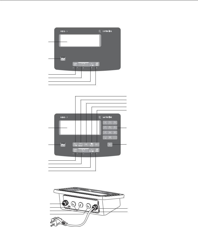
Display and Keypad
1Display
(For a detailed diagram, please see the chapter “Operating design”)
2 ON/Standby key
3 Zeroing key
4 Tare key
5 Function key (e.g. switch gross/net)
6 Print key (data output)
7Clear key (function applicationdependent)
8Reference value key (function application dependent)
9Transfer key (function application dependent)
10Toggle key (function application dependent)
11Info key for calling up identifiers and manual tare values
12Numeric keypad
13Identifier key for entering operator recognitions
14
15
16
17
|
|
Rear View |
|
14 |
Connector for weighing platform |
|
15 |
Menu access switch |
18 |
16 |
Optional: second interface (UniCOM) |
19 |
|
|
|
17 |
Optional: RS-232 interface (COM1) |
|
18 |
Power supply connection cable |
|
19 |
Ground connection |
|
|
(potential equalization) |
5

Start-up
Unpacking
§Unpack the device and check it immediately for any visible damage.
$If you detect any damage, proceed as directed in the chapter entitled “Care and Maintenance“, under “Safety
Inspection“.
$Save the box and all parts of the packaging for any future transport. Unplug all connected cables before packing the equipment.
Check package contents
–Indicator
–Operating instructions (this document)
–Options (special accessories) as listed on the bill of delivery; possible options are: Real-time clock with battery back-up Interface (RS-232, RS-485, analog interface 4-20 mA, digital I/O)
Internal rechargeable battery External rechargeable battery 24V module
Installation instructions
Avoid adverse influences at the place of installation:
–Heat (heater or direct sunlight; operational temperature: -10ºC to +40ºC)
–Drafts from open windows and doors
–Extreme vibrations during weighing
–Aggressive chemical vapors
–Extreme moisture (according to IP protection class)
Start up the device
$If necessary, acclimatize the device: see next column
§Connect the weighing platform and the indicator, see page 7 (any type of weighing platform or weighing cell that meets the required specifications can be connected to the indicator)
§Establish a connection to the power supply see the page after next
§Warm up the device: see the page after next (warm up time)
§Configure the analog/digital converter (ADC) see page 9
§Carry out an alignment: For calibration see page 21; for linearization see
page 20
Acclimatize the device
Condensation can form on the surfaces of a cold device when it is brought into a substantially warmer area. Therefore, on transferring the device to a warmer area make sure it is acclimatized for about 2 hours at room temperature (unplugged from power).
6

Connecting the Weighing Platform
Connection of an analog Sartorius platform MAPP, MAPS, or a commercially available strain-gauge load cell.
!The load cell should be connected by a certified technician who has received specialized training from Sartorius. Any installation work that does not conform to the instructions in this manual results in forfeiture of all claims under the manufacturer’s warranty.
!Disconnect the equipment from the power supply before starting connection work.
§Set up the weighing platform (see operating instructions for the weighing platform)
§Place the cable from the weighing platform next to the indicator
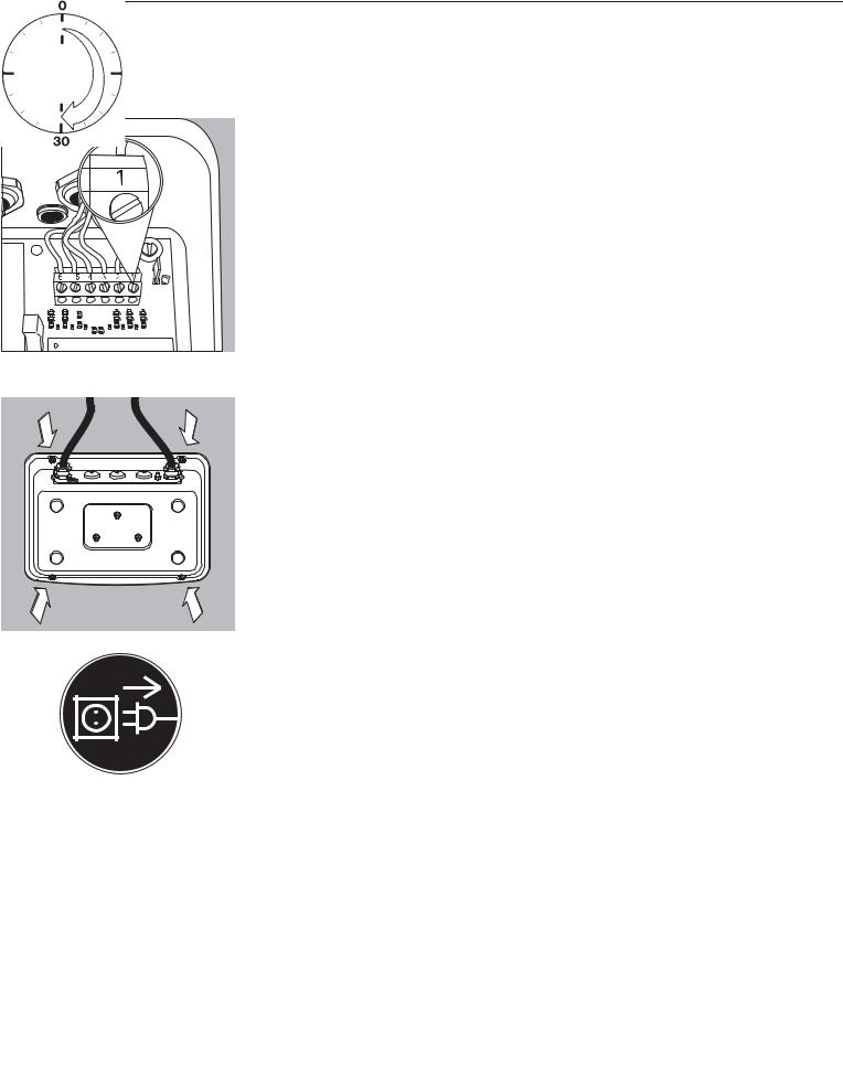
§Open the Midrics indicator:
Loosen the 4 cap nuts on the front panel. Remove the front panel.
§Connect the weighing platform connection cable to the indicator Note:
The cable gland is installed at the factory. Please use extreme caution when performing any work on the equipment that affects this gland.
Use a torque wrench.
Tighten the cable gland to: 5 Nm
§Strip the insulation of the cable and connect it as follows:
– Route the cable through the cable gland.
– Close and tighten the cable gland in accordance with the applicable regulations.
– Strip the insulation from the cable (according to the diagram). The shielding (1) must have contact with the clamps (2).
– Expose approximately 15 cm (3 inches) of the cable wires (3), so that they can be installed.
– Route the cable through the cable gland.
– Make sure the shield has contact with the clamps. The cable is grounded by the shield.
§Connect the cable to the weighing platform as follows:
–Strip the insulation from the cable. Expose approximately 5 cm (3 inches) of the cable wires (3), so that they can be installed.
–Strip approximately 1 cm (1/2 inch) of the insulation from the wires and affix ferrules to the wire ends.
–Place a ferrite ring over all the wires.
7
–Screw the wires tightly into the clamps
Indicator Pin Assignment:
No. |
Signal description |
Meaning |
1 |
BR_POS |
Bridge supply voltage (+) |
2 |
SENSE_POS |
Sense (+) for bridge supply voltage |
3 |
OUT_POS |
Measuring voltage positive |
4 |
OUT_NEG |
Measuring voltage negative |
5 |
SENSE_NEG |
Sense (-) for bridge supply voltage |
6 |
BR_NEG |
Bridge supply voltage (–) |
!Refer to the data sheet or operating instructions of the weighing platform for details on the assignment of wire colors/signals. Ensure any lines that are not assigned are insulated correctly.
!When connecting a load receptor that uses 4-conductor technology (the cable of the weighing platform to be connected only has 4 lines), connect clamp pairs 1 and 2 (BR_ and SENSE_POS), and 5 and 6 (SENSE_NEG and BR_NEG) with a wire jumper.
§Close the Midrics indicator:
Re-attach the front panel and secure it with the 4 cap nuts
Establishing a Connection to the Power Supply
§ Check the voltage rating and plug design.
$Power is supplied via the installed power cord that is supplied. The power supply is integrated into the indicator. The device can be operated with a voltage of 100 V to 240 V. The printed voltage rating (see type label) must match the voltage in the place of installation. If the stated supply voltage or the plug design of the power cord does not comply with the standard you use, please inform your nearest Sartorius representative or your dealer.
The power connection must be made in accordance with the regulations applicable in your country.
Connecting the device, rated to Class 1, to power supply (mains supply):
The device must be plugged into a properly installed wall outlet which has a protective grounding conductor (PE). The power plug or a different, suitable disconnecting device for the power must be easily accessible.
Safety Measures
If you use an electrical outlet that does not have a protective grounding conductor, ensure that an equivalent protective conductor is installed by a certified electrician
(as specified in the applicable regulations for installation in your country). The protective effect must not be negated by using an extension cord without a protective grounding conductor.
Warm-up Time
To return precise results, the device must warm up for at least 30 minutes after initial connection to the power supply. Only after this time will the device have reached the required operating temperature.
Using a verified device in legal metrology:
$Ensure that there is a warm-up time of at least 6 hours after initial connection to the power supply.
8

Analog/Digital Converter (ADC)
Purpose
Adjust the parameters of the analog/digital converter to the connected load cell or weighing platform.
After ADC configuration the ADC is defined as a scale in connection with the load sensor.
Set-up Information
–ADC configuration is only possible when the menu access switch is open. Close the menu access switch after ADC configuration, as otherwise there will not be any display of the conditions “overload” (“H”) and “underload” (“L”).
–When the service mode is active, the ADC configuration takes place in the Setup menu under “WP-1” under the menu item ADC-CON.
–Enter the maximum capacities in a suitable weight unit, without any decimal places (decimal places will be truncated by the rounding function).
! If you return to the highest level of the menu without saving the configuration parameter beforehand (menu item save) any settings that have been made will be deleted.
–Entries made in the ADC configuration will not be affected by a menu reset (returning the set-up parameters to their factory settings).
!Note:
Once the A/D converter configuration has been locked, the indicator can no longer be used to influence weighing results. The scope of functions available in the weighing instrument is defined by the A/D converter. Weighing functions that can be activated include reading weight values, taring, calibration, reading the tare value, saving/deleting the tare entry
Description of the Individual Menu Items for the A/C Converter Configuration
Standard or verifiable configuration (menu items STAND. / VERIF.)
In ADC configuration it is first selected, whether the weighing platform should be configured as a standard or verifiable (for use in legal metrology) weighing platform.
–Standard configuration (STAND.)
–Verifiable configuration (VERIF.).
Accuracy Class (menu item CLASS)
Only displayed in verifiable configuration.
Only menu items 3/4 (accuracy class l/m) can be selected. If the menu item is not already marked as being active with a circle (o), the ) key must be pressed once to activate it.
Range Selection (menu item RANGES)
Depending on the setting under this menu item, the menu points RANGE 1, RANGE 2 and RANGE 3 will either be displayed or will not be displayed for further configurations.
–Single range mode (SINGLE)
The entire weighing capacity is divided into decimal numbers dependent on the smallest scale interval d and the maximum weight. The readability corresponds to the scale interval d.
–Multi-interval scale (MULT.INT.) The function “multi-interval scale” divides the weighing capacity into a
maximum of three intervals with differing readability. The corresponding change takes place automatically at the defined interval limits. After taring, the best possible resolution (smallest scale intervals) is available even when there is a load on the weighing platform.
–Multiple range mode (MULT.R.)
A multiple-range scale has two or three weighing ranges. When the range limit for the lower weighing range is exceeded, the scale switches into the next highest weighing range (lower resolution). The scale only switches back to the higher resolution when the weighing platform has been completely unloaded.
Scale Interval d
The scale interval d indicates the resolution of the weighing instrument. The scale interval can only be entered in increments of 1, 2, 5, 10, 20, etc.
When “verifiable configuration” is used, this menu item is not displayed.
When using verifiable or verified weighing platforms (classes l and m), the scale interval d is the same as the verification scale interval e.
Verification Scale Interval e
The verification scale interval e indicates the resolution of the weighing instrument in legal metrology. The scale interval can only be entered in increments of 1, 2, 5, 10, 20, etc.
When “standard configuration” is used, this menu item is not displayed.
Maximum Capacity (max. cap.)
The maximum capacity is the maximum load that may be placed on the weighing platform. When heavier weights are used the weighing instrument displays overload “H”.
The scale intervals of the weighing instrument are calculated using the maximum capacity and the scale interval d (e.g. max. capacity = 15.000 kg, smallest scale interval = 0.005 kg yields 3000 scale intervals).
In legal metrology the total number of intervals must be no more than 3125 e, and when using multi-interval scales there must not be more than 3125 e intervals per range.
9
Range 1, Range 2, Range 3 (RANGE 1, RANGE 2, RANGE 3)
The range limits are entered for the individual ranges. The accuracy changes when these limits are exceeded.
The following applies when entering limits:
Range 1 < Range 2 < Range 3 < Max. cap.
This means that the weighing range can be divided into a maximum of 4 ranges. The resolution changes at intervals of 1, 2, 5, 10, 20 etc., where the lowest resolution is the smallest scale interval entered. Set ranges that are not required for use to zero.
Available weighing units (menu item UNITS)
This menu item is used to select the weighing units that have been cleared for use in weighing. All units marked with a circle (o) have been cleared for use, multiple selection is possible.
If you need to use this indicator as a legal measuring instrument (legal for trade), be sure you have selected a permissible unit.
Save parameters (menu item SAVE)
The ADC configuration data is saved once at the end of defining the settings using the SAVE function.
Testing and configuration
for operation in legal metrology
A metrology plate is included in the scope of supply of the indicator. Once ADC configuration is complete, record the metrological data for all ranges on the metrology plate. Attach the plate underneath the display and
cover with the supplied waterproof foil.
Under menu item 1.7, check that only authorized weight units can be selected.
Menu Structure for ADC Configuration
The setup menu for WP1 (“WP-1”) can be extended to include the following additional setting options for ADC configuration:
ADC CON |
|
|
|
|
ADC configuration |
|||||||||
|
|
STAND. |
|
|
|
|
Standard configuration |
|||||||
|
|
|
|
|
|
|||||||||
|
|
|
|
RANGES |
|
|
|
|
Range selection |
|||||
|
|
|
|
|
|
|
|
|||||||
|
|
|
|
|
|
SINGLE |
|
|
|
WEIGHTS |
Single range mode |
|||
|
|
|
|
|
|
|
|
|
||||||
|
|
|
|
|
|
|
|
|
|
|
|
D |
Scale interval |
|
|
|
|
|
|
|
|
|
|
|
|
|
|||
|
|
|
|
|
|
|
|
|
|
|
|
|
|
Enter value |
|
|
|
|
|
|
|
|
|
|
|
|
|
|
|
|
|
|
|
|
|
|
|
|
|
|
|
MAX |
Max. cap. |
|
|
|
|
|
|
|
|
|
|
|
|
|
|||
|
|
|
|
|
|
|
|
|
|
|
|
|
|
Enter value |
|
|
|
|
|
|
|
|
|
|
|
|
|
|
|
|
|
|
|
|
|
MULT.INT |
|
WEIGHTS |
Multi-interval scale |
|||||
|
|
|
|
|
|
|
||||||||
|
|
|
|
|
|
|
|
|
|
|
|
D |
Scale interval |
|
|
|
|
|
|
|
|
|
|
|
|
|
|||
|
|
|
|
|
|
|
|
|
|
|
|
|
|
Enter value |
|
|
|
|
|
|
|
|
|
|
|
|
|
|
|
|
|
|
|
|
|
|
|
|
|
|
|
RANGE 1 |
Range limit 1 |
|
|
|
|
|
|
|
|
|
|
|
|
|
|||
|
|
|
|
|
|
|
|
|
|
|
|
|
|
Enter value |
|
|
|
|
|
|
|
|
|
|
|
|
|
|
|
|
|
|
|
|
|
|
|
|
|
|
|
RANGE 2 |
Range limit 2 |
|
|
|
|
|
|
|
|
|
|
|
|
|
|||
|
|
|
|
|
|
|
|
|
|
|
|
|
|
Enter value |
|
|
|
|
|
|
|
|
|
|
|
|
|
|
|
|
|
|
|
|
|
|
|
|
|
|
|
RANGE 3 |
Range limit 3 |
|
|
|
|
|
|
|
|
|
|
|
|
|
|||
|
|
|
|
|
|
|
|
|
|
|
|
|
|
Enter value |
|
|
|
|
|
|
|
|
|
|
|
|
|
|
|
|
|
|
|
|
|
|
|
|
|
|
|
MAX |
Max. cap. |
|
|
|
|
|
|
|
|
|
|
|
|
|
|||
|
|
|
|
|
|
|
|
|
|
|
|
|
|
Enter value |
|
|
|
|
|
|
|
|
|
|
|
|
|
|
|
|
|
|
|
|
|
MULT.R. |
|
WEIGHTS |
Multiple-range scale |
|||||
|
|
|
|
|
|
|
||||||||
|
|
|
|
|
|
|
|
|
|
|
|
D |
Scale interval |
|
|
|
|
|
|
|
|
|
|
|
|
|
|||
|
|
|
|
|
|
|
|
|
|
|
|
|
|
Enter value |
|
|
|
|
|
|
|
|
|
|
|
|
|
|
|
|
|
|
|
|
|
|
|
|
|
|
|
RANGE 1 |
Range limit 1 |
|
|
|
|
|
|
|
|
|
|
|
|
|
|||
|
|
|
|
|
|
|
|
|
|
|
|
|
|
Enter value |
|
|
|
|
|
|
|
|
|
|
|
|
|
|
|
|
|
|
|
|
|
|
|
|
|
|
|
RANGE 2 |
Range limit 2 |
|
|
|
|
|
|
|
|
|
|
|
|
|
|||
|
|
|
|
|
|
|
|
|
|
|
|
|
|
Enter value |
|
|
|
|
|
|
|
|
|
|
|
|
|
|
|
|
|
|
|
|
|
|
|
|
|
|
|
RANGE 3 |
Range limit 3 |
|
|
|
|
|
|
|
|
|
|
|
|
|
|||
|
|
|
|
|
|
|
|
|
|
|
|
|
|
Enter value |
|
|
|
|
|
|
|
|
|
|
|
|
|
|
|
|
|
|
|
|
|
|
|
|
|
|
|
MAX |
Max. cap. |
|
|
|
|
|
|
|
|
|
|
|
|
|
|
|
Enter value |
|
|
|
|
|
|
|
|
|
|
|
|
|
|
|
|
|
|
|
|
|
|
|
|
|
|
|
|
|
|
10
|
|
|
UNITS |
FREE |
User-defined unit |
|
Available weight units |
||||||||
|
|
|
|||||||||||||
|
|
|
|
|
|
|
|
||||||||
|
|
|
|
|
|
|
|
||||||||
|
|
|
|
|
|
G |
Gram |
|
|
||||||
|
|
|
|
|
|
|
|
||||||||
|
|
|
|
|
|
KG |
Kilogram |
|
|
||||||
|
|
|
|
|
|
|
|
||||||||
|
|
|
|
|
|
CT |
Carat |
|
|
||||||
|
|
|
|
|
|
|
|
||||||||
|
|
|
|
|
|
LB |
Pound |
|
|
||||||
|
|
|
|
|
|
|
|
||||||||
|
|
|
|
|
|
OZ |
Ounce |
|
|
||||||
|
|
|
|
|
|
|
|
||||||||
|
|
|
|
|
|
OZT |
Troy ounce |
|
|
||||||
|
|
|
|
|
|
|
|
||||||||
|
|
|
|
|
|
TLH |
Hong Kong taels |
|
|
||||||
|
|
|
|
|
|
|
|
||||||||
|
|
|
|
|
|
TLS |
Singapore taels |
|
|
||||||
|
|
|
|
|
|
|
|
||||||||
|
|
|
|
|
|
TLT |
Taiwan taels |
|
|
||||||
|
|
|
|
|
|
|
|
||||||||
|
|
|
|
|
|
GN |
Grain |
|
|
||||||
|
|
|
|
|
|
|
|
||||||||
|
|
|
|
|
|
DWT |
Pennyweights |
|
|
||||||
|
|
|
|
|
|
|
|
||||||||
|
|
|
|
|
|
MG |
Milligram |
|
|
||||||
|
|
|
|
|
|
|
|
||||||||
|
|
|
|
|
|
/LB |
Parts per pound |
|
|
||||||
|
|
|
|
|
|
|
|
||||||||
|
|
|
|
|
|
TLC |
Chinese taels |
|
|
||||||
|
|
|
|
|
|
|
|
||||||||
|
|
|
|
|
|
MOM |
Mommes |
|
|
||||||
|
|
|
|
|
|
|
|
||||||||
|
|
|
|
|
|
K |
Austrian carat |
|
|
||||||
|
|
|
|
|
|
|
|
||||||||
|
|
|
|
|
|
TOL |
Tola |
|
|
||||||
|
|
|
|
|
|
|
|
||||||||
|
|
|
|
|
|
BAT |
Baht |
|
|
||||||
|
|
|
|
|
|
|
|
||||||||
|
|
|
|
|
|
MS |
Mesgahl |
|
|
||||||
|
|
|
|
|
|
|
|
||||||||
|
|
|
|
|
|
T |
Ton |
|
|
||||||
|
|
|
|
|
|
|
|
||||||||
|
|
|
|
|
|
LB/OZ |
Pounds per ounce |
|
|
||||||
|
|
|
SAVE |
|
|
||||||||||
|
|
|
NO |
|
|
|
|
|
|
||||||
|
|
|
|
|
|
|
|
||||||||
|
|
|
|
|
|
|
|
|
|
|
|
||||
|
|
|
|
|
|
|
|
|
|
|
|
||||
|
|
|
|
|
|
YES |
|
|
|
|
|
|
|||
VERIF. |
|
|
|
|
|
Verifiable configuration |
|||||||||
|
|
|
|
|
|
|
|
|
|||||||
|
|
|
CLASS |
3/4 |
|
|
|
|
|
|
|
|
Accuracy class |
||
|
|
|
|
|
|
|
|
|
|||||||
|
|
|
|
|
|
|
|
|
|
|
|
|
|
|
|
|
|
|
RANGES |
|
|
|
|
|
Range selection |
||||||
|
|
|
|
|
|
|
|
|
|
|
|
||||
|
|
|
|
|
|
|
|
|
|
||||||
|
|
|
|
|
|
SINGLE |
|
|
WEIGHTS |
|
Single range mode |
||||
|
|
|
|
|
|
|
|
||||||||
|
|
|
|
|
|
|
|
|
|
|
|
E |
|
Verifiable scale interval |
|
|
|
|
|
|
|
|
|
|
|
|
|
||||
|
|
|
|
|
|
|
|
|
|
|
|
|
|
|
Enter value |
|
|
|
|
|
|
|
|
|
|
|
|
|
|
||
|
|
|
|
|
|
|
|
|
|
|
|
MAX |
|
Max. cap. |
|
|
|
|
|
|
|
|
|
|
|
|
|
||||
|
|
|
|
|
|
|
|
|
|
|
|
|
|
|
Enter value |
|
|
|
|
|
|
|
|
|
|
|
|
|
|
||
|
|
|
|
|
|
MULT.INT |
|
WEIGHTS |
|
Multi-interval scale |
|||||
|
|
|
|
|
|
|
|||||||||
|
|
|
|
|
|
|
|
|
|
|
|
E |
|
Verifiable scale interval |
|
|
|
|
|
|
|
|
|
|
|
|
|
||||
|
|
|
|
|
|
|
|
|
|
|
|
|
|
|
Enter value |
|
|
|
|
|
|
|
|
|
|
|
|
|
|
|
|
|
|
|
|
|
|
|
|
|
|
|
|
RANGE 1 |
|
Range limit 1 |
|
|
|
|
|
|
|
|
|
|
|
|
|
||||
|
|
|
|
|
|
|
|
|
|
|
|
|
|
|
Enter value |
|
|
|
|
|
|
|
|
|
|
|
|
|
|
|
|
|
|
|
|
|
|
|
|
|
|
|
|
RANGE 2 |
|
Range limit 2 |
|
|
|
|
|
|
|
|
|
|
|
|
|
||||
|
|
|
|
|
|
|
|
|
|
|
|
|
|
|
Enter value |
|
|
|
|
|
|
|
|
|
|
|
|
|
|
|
|
|
|
|
|
|
|
|
|
|
|
|
|
RANGE 3 |
|
Range limit 3 |
|
|
|
|
|
|
|
|
|
|
|
|
|
||||
|
|
|
|
|
|
|
|
|
|
|
|
|
|
|
Enter value |
|
|
|
|
|
|
|
|
|
|
|
|
|
|
|
|
|
|
|
|
|
|
|
|
|
|
|
|
MAX |
|
Max. cap. |
|
|
|
|
|
|
|
|
|
|
|
|
|
||||
|
|
|
|
|
|
|
|
|
|
|
|
|
|
|
Enter value |
|
|
|
|
|
|
|
|
|
|
|
|
|
|
|
|
|
|
|
|
|
|
MULT.R. |
|
|
WEIGHTS |
|
Multiple-range scale |
||||
|
|
|
|
|
|
|
|
||||||||
|
|
|
|
|
|
|
|
|
|
|
|
E |
|
Verifiable scale interval |
|
|
|
|
|
|
|
|
|
|
|
|
|
||||
|
|
|
|
|
|
|
|
|
|
|
|
|
|
|
Enter value |
|
|
|
|
|
|
|
|
|
|
|
|
|
|
|
|
|
|
|
|
|
|
|
|
|
|
|
|
RANGE 1 |
|
Range limit 1 |
|
|
|
|
|
|
|
|
|
|
|
|
|
||||
|
|
|
|
|
|
|
|
|
|
|
|
|
|
|
Enter value |
|
|
|
|
|
|
|
|
|
|
|
|
|
|
|
|
|
|
|
|
|
|
|
|
|
|
|
|
RANGE 2 |
|
Range limit 2 |
|
|
|
|
|
|
|
|
|
|
|
|
|
||||
|
|
|
|
|
|
|
|
|
|
|
|
|
|
|
Enter value |
|
|
|
|
|
|
|
|
|
|
|
|
|
|
|
|
|
|
|
|
|
|
|
|
|
|
|
|
RANGE 3 |
|
Range limit 3 |
|
|
|
|
|
|
|
|
|
|
|
|
|
||||
|
|
|
|
|
|
|
|
|
|
|
|
|
|
|
Enter value |
|
|
|
|
|
|
|
|
|
|
|
|
|
|
|
|
|
|
|
|
|
|
|
|
|
|
|
|
MAX |
|
Max. cap. |
|
|
|
|
|
|
|
|
|
|
|
|
|
||||
|
|
|
UNITS |
|
See above |
|
|
|
|
|
Enter value |
||||
|
|
|
|
|
|
|
|
|
|||||||
|
|
|
|
|
|
|
|
|
|
||||||
|
|
|
|
|
|
|
|
|
|||||||
|
|
|
SAVE |
NO |
|
|
|
|
|
|
|||||
|
|
|
|
|
|
|
|
||||||||
|
|
|
|
|
|
|
|
|
|
|
|
||||
|
|
|
|
|
|
|
|
|
|
|
|
||||
|
|
|
|
|
|
YES |
|
|
|
|
|
|
|||
|
|
|
|
|
|
|
|
|
|
|
|
||||
11

Service Menu
Purpose
The service menu enables access to additional menu items in the setup menu, which are not displayed when the service mode is not active.
The most important calibration and adjustment work for the indicator and for the connected weighing platform can be carried out in the service menu.
When the Service mode is active, an “S” is shown in the top right-hand corner of the display. To deactivate the Service mode, restart the indicator (turn the indicator off and back on again).
The following additional functions are available in the service mode:
The following are the menu items displayed behind the menu items date (“DATE”) and code (“CODE”):
–Service date “S DATE”
(Entry of the next service date)
–Memory number “MEM NO”
(Entry of a transaction code for an external Alibi memory)
–Serial number of the indicator ”SER NO”
–Model description “model”
(Entry of the device serial number)
12
Activating the Service Mode
e
)
k k
Switch the device on and immediately (during the initialization of the device) press ...
... briefly to display the menu
Select the Setup menu item
setup
)
Confirm the setup menu item 1)
wp-1
k
code
)
)
Select the code menu item
(press key k until the code appears on the display)
Confirm the code menu item and enter the service password (see Appendix) Use keys ( ) k p
Saving the service password
When the service mode is activated an “S”appears in the top right-hand corner of the display.
( |
Return to “Code” in the service mode. |
code
(
Return to “Setup” in the service mode.
1) If a password is requested at this point, enter the service password (see Appendix) and continue once the service password has been accepted.
13
)
wp-1
)
k repeatedly
ADC-CON
)
STAND.
SAVE
Configuring the A/D Converter
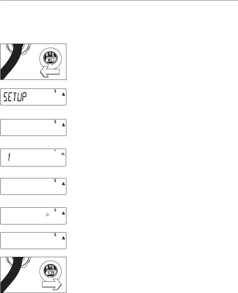
Open the menu access switch
§Remove the cap that covers the menu access switch on the left-hand side of the back of the indicator
§To do this, move the switch to the left (towards the interface connectors). (“open position”)
Activate the service mode (see page 13)
Select weighing platform and confirm: Press the ) key
To select the menu item ADC configuration, press the k key several times until ADC-CON appears. To confirm the menu item ADC configuration, press ).
Select whether a standard configuration (STAND) or a verifiable configuration (VERIF.) should be carried out (in this example, standard configuration).
See the next page for a detailed description of the procedure
Once you have completed the configuration, save the data using the menu item SAVE.
The A/D converter can now be treated like any standard weighing platform in connection with the load sensor.
Close the menu access switch
Once ADC configuration has been completed, an adjustment of the weighing platform (calibration/adjustment and linearization) must be carried out (see page 21 “Calibration/adjustment” and page 23 “Calibration without weights”)
14
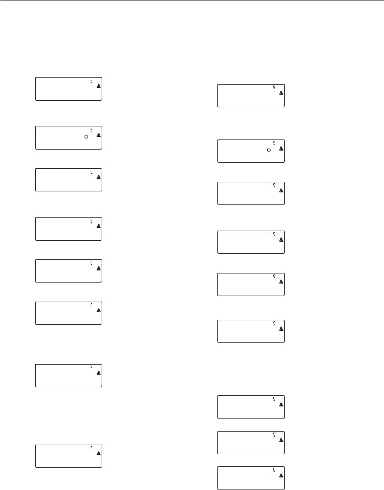
Example 1:
Enter or change values for standard configuration in single range mode in the unit set under 1.7.x.
ADC-CON |
Select menu item ADC CON |
) |
Confirm menu item ADC CON |
(if necessary k) |
to select the menu item STAND |
Stand. |
Standard configuration |
) |
Confirm menu item STAND. |
Ranges |
Range selection |
) |
Confirm menu item RANGES |
(if necessary press k repeatedly) Select menu item SINGLE |
|
SINGle |
Single range mode |
( |
Confirm menu item SINGLE |
Weights |
Weights |
) |
Confirm menu item WEIGHTS |
d |
Scale interval |
) |
Confirm menu item D |
( ) k p |
Enter a value (e.g. 0.002 kg) |
(if necessary press ) repeatedly) until display D appears |
|
k |
Select menu item MAX. |
max. |
Maximum capacity |
) |
Confirm menu item MAX. |
( ) k p |
Enter a value (e.g. 30 kg) |
(if necessary press ) repeatedly) until display MAX appears |
|
( |
Menu item UNITS is displayed |
(if necessary press the ) key) |
to select available |
|
weighing units (UNITS) |
k |
Menu item SAVE is displayed |
Save |
|
) k ) |
Save the entered value (YES) |
|
or do not save (NO) |
Example 2:
Enter or change values for standard configuration in a multiinterval scale in the unit set under 1.7.x.
(the same applies for multiple range mode).
ADC-CON 
)
(if necessary press
) k p)
Stand.
)
Ranges
)
(if necessary press k repeatedly)
Mult.Int 
(
Weights 
)
d
)
( ) k p
(if necessary press ) repeatedly) k
Range 1 
Range 2 
max.
Select menu item ADC CON
Confirm menu item ADC CON and select the menu item STAND.
Standard configuration
Confirm menu item STAND.
Range selection
Confirm menu item RANGES Select menu item MULT. INT
Multi-interval scale
Confirm menu item MULT. INT
Weights
Confirm menu item WEIGHTS
Scale interval (e.g. 0.002 kg)
Confirm menu item D
Enter a value (e.g. 0.002 kg) until display D appears Select menu item RANGE 1
Enter values for the following in the same way:
Range limit 1 (e.g. 6 kg)
Range limit 2 (e.g. 15 kg)
Maximum capacity (e.g. 30 kg)
Continue as shown in example 1 after entering the maximum capacity
15
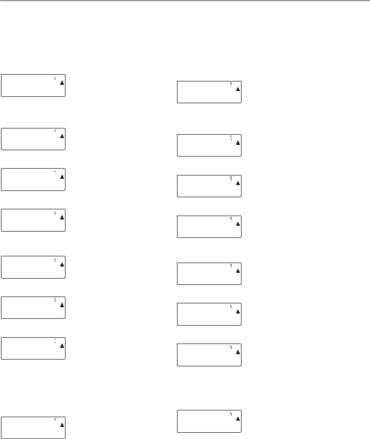
Example 3:
Enter or change values for verifiable configuration in single range mode in the unit set under 1.7.x.
ADC-CON |
Select menu item ADC CON |
) |
Confirm menu item ADC CON |
(if necessary press |
and select the menu item VERIF. |
) k p) |
|
Verif. |
Verifiable configuration |
) |
Confirm menu item VERIF. |
Class |
Accuracy class |
(if necessary press ) ) () |
To confirm accuracy class 3/4 |
Ranges |
Range selection |
) |
Confirm menu item RANGES |
(if necessary press k repeatedly) Select menu item SINGLE |
|
SINGle |
Multi-interval scale |
( |
Confirm menu item SINGLE |
Weights |
Weights |
) |
Confirm menu item WEIGHTS |
E |
Verifiable scale interval |
) |
Confirm menu item E |
( ) k p |
Enter a value (e.g. 0.002 kg) |
(if necessary press ) repeatedly) until display E appears |
|
k |
Select menu item MAX. |
|
Enter values for the following in |
|
the same way: |
max. |
Maximum capacity (e.g. 30 kg) |
|
Continue as shown in example 1 |
after entering the maximum capacity
Example 4:
Enter or change values for verifiable configuration in a multi-inter- val scale in the unit set under 1.7.x.
(the same applies for multiple range mode).
ADC-CON |
Select menu item ADC CON |
) |
Confirm menu item ADC CON |
(if necessary press |
|
) k p) |
and select the menu item VERIF. |
Verif. |
Verifiable configuration |
) |
Confirm menu item VERIF. |
Class |
Accuracy class |
(if necessary press ) ) () To confirm accuracy class 3/4 |
|
Mult.Int |
Range selection |
) |
Confirm menu item RANGES |
(if necessary press k repeatedly) Select menu item MULT. INT |
|
Mult.Int |
Multi-interval scale |
( |
Confirm menu item MULT. INT |
Weights |
Weights |
) |
Confirm menu item WEIGHTS |
E |
Verifiable scale interval |
) |
Confirm menu item E |
( ) k p |
Enter a value (e.g. 0.002 kg) |
(if necessary press ) repeatedly) until display E appears |
|
k |
Select menu item RANGE 1 |
|
Enter values for the following in |
|
the same way: |
Range 1 |
Range limit 1 (e.g. 6 kg) |
|
Range limit 2 (e.g. 15 kg) |
|
Maximum capacity (e.g. 30 kg) |
Continue as shown in example 1 after entering the maximum capacity
16

Key ) - > 2 sec Function
Allocation
Purpose
The key ) - > 2 sec is usually used for the calibration/adjustment function. The following additional functions can be allocated to the key when the service mode is activated:
–External linearization with default weights (menu item 1.9.6)
–External linearization with the linearization weights (menu item 1.9.7) entered under menu item 1.18
–Setting the preload (menu item 1.9.8)
–Clearing the preload (menu item 1.9.9)
!Once linearization has been completed, or after a preload has been set or cleared the function of the key )- > 2 sec must be reallocated back to its normal function in the Setup menu (e.g. external calibration/adjustment with default weights)
Menu structure for key ) - > 2 sec function allocation
1. 9. |
|
|
Calibration, adjustment |
|
|
|
1. 9. |
1 |
External calibration/adjustment with default weights (service mode not required) |
|
|
|||
|
|
1. 9. |
3 |
External calibration/adjustment with user-defined weights (entered under 1-18), (service mode not required) |
|
|
|||
|
|
1. 9. |
6 |
External linearization with default weights |
|
|
|||
|
|
1. 9. |
7 |
External linearization with user-defined weights (entered under 1-18) |
|
|
|||
|
|
1. 9. |
8 |
Set preload |
|
|
|||
|
|
1. 9. |
9 |
Clear preload |
|
|
|||
|
|
1. 9. |
10 |
Key blocked |
|
|
|||
17

Entering Geographical
Data
Purpose
Entering geographical data allows the external calibration of weighing
equipment at a place (e.g. at the manufacturer or vendor’s place of business) that is not the same as the place of installation. If the weighing equipment is calibrated at the place of installation, it is not necessary to enter geographical data.
The sensitivity of weighing equipment changes depending on the place of installation as it is dependent on the on-site gravitational force – or, more precisely, on gravitational acceleration. Saving geographical data makes it possible to change the place of installation of the weighing equipment after external adjustment has been carried out.
The calibration of weighing equipment is valid at the place of installation and within a specific tolerance zone. At 3000 e this zone extends ±100 km from the set geographical latitude and ±200 m from the set elevation above sea level.
An exception to this is the setting for “Germany (Zone D)”:
If during external calibration of weighing equipment within Germany the geographical data
–51.00° geographical latitude
–513 m elevation above sea level
are entered, the weighing equipment can be used throughout Germany. Gravitational acceleration for “Germany (Zone D)” is 9.810 m/s?.
On delivery the geographical data for “Germany (Zone D)” are entered in the output device.
It is recommended to use the geographical data settings for “Germany (Zone D)” when calibrating and delivering the weighing equipment within Germany. Entering exact geographical data will lead to a higher level of accuracy but will also restrict the tolerance zone.
Set-up Information
–It is only possible to enter geographical data when the menu access switch is open.
–Geographical data can be entered when the service mode in the Setup menu for “WP 1” is activated. The settings are made in the corresponding Setup menu under menu item 1.20.
–Either the geographical latitude in degrees (menu item 1.20.1) and elevation in m above sea level (menu item 1.20.2), or the value for gravitational acceleration (menu item 1.20.3) can be entered.
Gravitational acceleration takes precedence over the geographical latitude and elevation of the location: If it has been entered, input fields for latitude and elevation show the values 99999.99 and 9999999 respectively. If only elevation and latitude have been entered, 0000000 is displayed for gravitational acceleration.
!If you return to the highest level of the Setup menu without saving the configuration parameter beforehand (menu item 1.20.4) any settings that have been made will be deleted.
Procedure
–Open the menu access switch. If the device is part of a verified weighing facility, this will only be possible if the verification seal is broken. The weighing equipment must then be verified again.
–Activating the service mode
–Select the weighing platform
–Enter the geographical data for the place of calibration under menu items 1.20.1 to 1.20.3 and save them under menu item 1.20.4. The data can be obtained from the relevant land registry or Ordnance Survey.
–Carry out external calibration (see page 20)
–After the calibration, enter the geographical data for the place of installation under menu items 1.20.1 to 1.20.3 and save them under menu item 1.20.4.
–Close the menu access switch.
–The weighing equipment can now be operated at the place of installation, and within the abovementioned tolerance zone.
Note:
The set geographical values are displayed during the calibration procedure if the display of the data has been activated in the Setup menu under “utilit” menu item 8.12.2 (factory setting: 8.12.1, display deactivated).
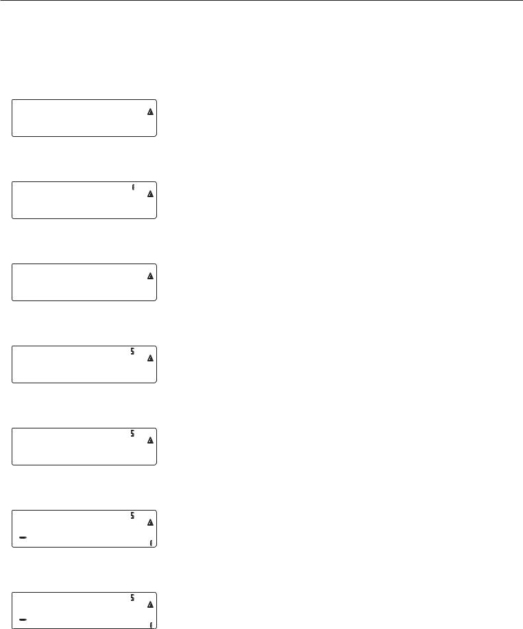
When the display of the geographical data is activated the calibration procedure is as follows:
If the elevation and geographical latitude are used, after the start of the calibration procedure “CAL” the word “ALTITUDE” will appear briefly followed by the set elevation (in meters above sea level). The display is confirmed using the ) key (and cancelled using
the ( key). Then, the word “LATITUDE” will be displayed briefly, followed by the set geographical latitude in degrees. This can also be confirmed using the ) key (and cancelled using the ( key). After this, you will be prompted to place the calibration weight on the platform. If gravitational acceleration has been entered instead of elevation and geographical latitude, the word “GRAVITY” will appear briefly, followed by the set value for gravitational acceleration. The display is confirmed using the ) key (and cancelled using the ( key).
Menu Structure for Entering the Geographical Data
1. 20. |
|
|
Calibration location (geographical latitude and elevation; or alternatively the gravitational acceleration |
|
|
|
|
|
at the place of installation) |
|
|
1. 20. 1 |
Latitude in degrees |
|
|
|
|||
|
|
1. 20. 2 |
Elevation in meters above sea level |
|
|
|
|||
|
|
1. 20. 3 |
Gravitational acceleration |
|
|
|
|||
|
|
1. 20. 4 |
Save values for 1. 20 |
|
|
|
|||
18

Enter Calibration
and Linearization Weights
Purpose
Entering the calibration and linearization weights
Set-up information
–The service mode must be activated in order for linearization weights to be entered under menu items 1.18.2 to 1.18.5.
–Calibration and linearization weights are entered in the Setup menu under “WP 1”. The settings are made in the corresponding Setup menu under menu item 1.18.
–The service mode must be activated in order for external user-defined calibration weights to be entered under menu item 1.18.1.
Procedure
–Activate the service mode (only necessary if linearization weights are going to be entered)
–Select the weighing platform.
–Enter the external user-defined calibration weight under menu item 1.18.1
–Enter the external linearization weight under menu items 1.18.2 to 1.18.5.
Menu structure for entering the calibration and linearization weights
1. 18. |
|
Entering the calibration and linearization weights |
|
|
|
1. 18. 1 |
Entering external user-defined calibration weight (service mode not required) |
|
|
||
|
|
1. 18. 2 |
Enter lin. weight 1 |
|
|
||
|
|
1. 18. 3 |
Enter lin. weight 2 |
|
|
||
|
|
1. 18. 4 |
Enter lin. weight 3 |
|
|
||
|
|
1. 18. 5 |
Enter lin. weight 4 |
|
|
||
19
External Linearization
Set-up information
! External linearization when weighing in legal metrology is only possible when the menu access switch is open.
–The external linearization function must be allocated to the key ) –> 2 (menu item 1.9.6 or 1.9.7).
Procedure
(
) > 2 sec
!After external linearization, close the menu access switch and reallocate the original function back to the key ) –> 2 sec (e.g. external calibration/ adjustment with user-defined weights) under menu item 1.9.
Zero the weighing platform.
Start linearization.
After approximately 2 seconds you will be prompted to place the first linearization weight on the platform.
Place the required amount on the platform. After a short time the difference between the measured value and the true weight of the sample will be displayed.
) |
Save the linearization weight (cancel using the ( key). |
|
You will then be prompted to place the second linearization weight on the platform. |
|
Repeat the procedure for all required linearization weights. |
After the last linearization weight has been saved you will be prompted to remove any load from the weighing pan.
Unload the weighing pan. After a short period of time the zero point will automatically be adopted and the indicator will automatically switch back into weighing mode.
20
Calibration, Adjustment
Purpose
The accuracy of the measurement results must be checked. This is carried out using calibration and adjustment.
Perform calibration to determine the difference between the value displayed and the actual weight on the platform. Calibration does not entail making any changes within the weighing equipment.
During adjustment, the difference between the measured value displayed and the true weight of a sample is corrected, or is reduced to an allowable level within maximum permissible error limits.
Features
The configured weighing platform determines which of the following features are available:
–External adjustment with the weight
of the factory setting – standard weight (1.9.1), not for use in verified weighing instruments
–External calibration with a user-defined weight (1.9.3), not for use in verified weighing instruments
–Block the key ) –> 2 sec to prevent use of the functions described above (1.9.10):
–Calibration with automatic adjustment (1.10.1), not for use in verified weighing instruments
–Calibration with the option of activating the adjustment function manually (1.10.2)
–Adjustment prompt – flashing W symbol (1.15.2).
–Block external adjustment (1.16.2)
–Display of elevation and geographical latitude, or gravitational acceleration after CAL has been displayed at the start of the calibration procedure (menu item 8.12.2). These values will only be displayed if they have been entered and activated in the service menu.
For each of the parameters elevation, geographical latitude and gravitational acceleration, the term is displayed first (Altitude, Latitude or Gravity) for 1 second, and then the corresponding value is displayed continuously until you press the ) key.
Note
When using verified weighing instruments, the external calibration function can only be used when the menu access switch is open once the verification seal has been broken. The device must then be verified again.
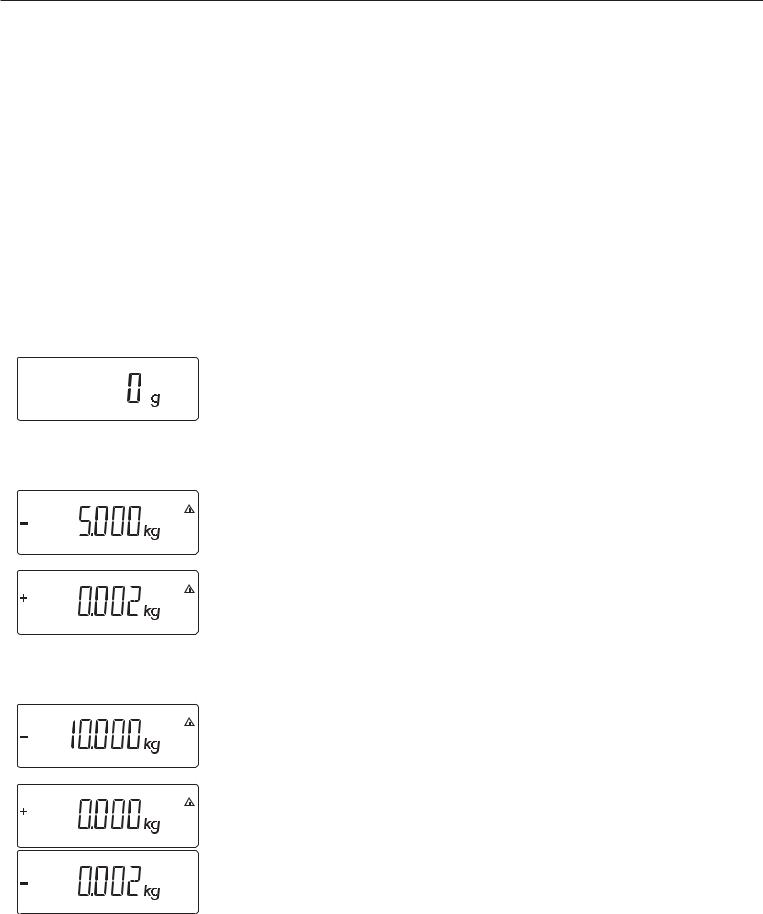
Example
External calibration and manual adjustment with standard weights
Pre-settings in Setup: 1.9.1; 1.10.2
( |
Unload and zero the scale |
)>2 sec |
Start calibration (e.g. when adjustment prompt (W Symbol) flashes) |
|
This display appears for 2 seconds |
c.ext.def |
|
|
You will then be prompted to place the calibration/adjustment weight on the platform |
|
(e.g. 10 kg) |
21
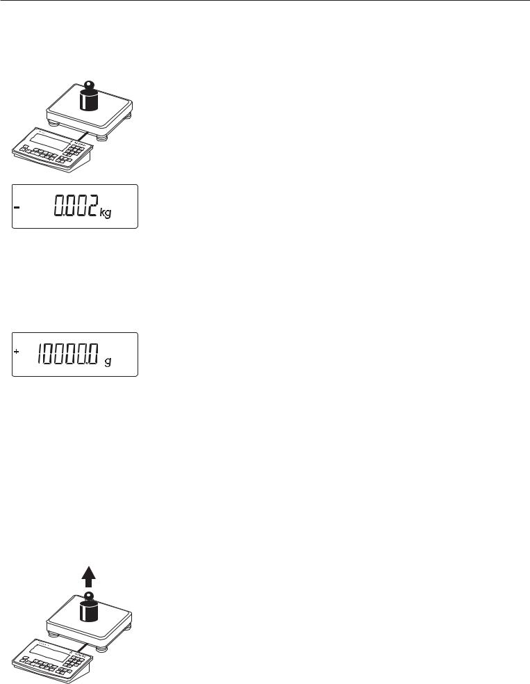
Position the calibration/adjustment weight on the weighing platform
The difference between the measured value and the true weight of the sample will be disayed with plus/minus signs.
External calibration |
A printout will be generated if the calibration is not carried out and the procedure |
|
Nom + |
10000 g |
can be stopped by pressing the ( key. |
Diff. - |
2 g |
|
-------------------- |
|
|
) |
|
Activate calibration manually (press the ( key to stop calibration/adjustment) |
The calibration weight is displayed once calibration is finished.
-------------------- |
|
A GMP-compliant printout is generated |
14.01.2007 |
13:00 |
|
Type |
|
MIS2 |
Ser.no. |
|
12345678 |
Vers. |
1.1007.12.1 |
|
BVers. |
|
01-25-01 |
--------------------
External calibration
Nom + |
10000 |
g |
Diff. - |
2 |
g |
External calibration
Diff. + |
0 g |
--------------------
14.01.2007 |
13:02 |
Name: |
|
--------------------
Unload the weighing equipment
22

Set Preload
Set-up Information
! It is only possible to set a preload when the menu access switch is open.
–The function set preload (menu item 1.9.8) must be allocated to the key ) - > 2 sec (see page 17).
!After setting a preload, close the menu access switch and reallocate the original function back to the key ) - > 2 sec (e.g. external calibration/adjustment with user-defined weights) under menu item 1.9.
Calibration/Adjustment without Weights
In the service menu, calibration without weights can be carried out by entering the characteristic data of the load cells (e.g. hopper weighing area with known characteristic data of the load cells)
Set-up information
!Calibration without weights may not be carried out on weighing equipment
used in legal metrology.
–Calibration without weights is only possible when the menu access switch is open in the service menu.
Clear Preload
Set-up Information
! It is only possible to clear a preload when the menu access switch is open.
–The function clear preload (menu item 1.9.9) must be allocated to the key ) - > 2 sec (see page 17).
!After clearing a preload, close the menu access switch and reallocate the original function back to the key ) - > 2 sec (e.g. external calibration/adjustment with user-defined weights) under menu item 1.9.
–The parameters necessary for calibration without weights are entered in the Setup menu under “WP 1” when the service mode is activated. The settings are made in the corresponding Setup menu under menu item 1.19.
–The parameter “Nominal capacity” must be entered in the unit that is set under 1.7.x.
–The parameter “Sensitivity” is entered in mV/V (take value from e.g. the data sheet).
–Note:
The data entered are saved by selecting menu item “1.19.8”. After saving, the data will no longer be able to be read.
Procedure
–Open the menu access switch
–Activating the service mode
–Select the weighing platform
–Enter the nominal load of the load cell(s) under menu item 1.19.1. If the weighing platform has multiple load cells, the nominal capacity must be multiplied accordingly (e.g. 4 load cells, each of which has a capacity of 50 kg, will produce a nominal capacity
of 200 kg)
–Enter the sensitivity of the load cells in mV/V under menu item 1.19.3.
–If the weighing platform has multiple load cells, either the individual values for the load cells will be entered in 1.19.3 to 1.19.6, or the average value for all the cells will be entered in 1.19.3.
–Enter the dead load of a hopper construction in mV/V in 1.19.7.
–Save the values for calibration without weighing under menu item 1.19.8.
–Close the menu access switch
Menu Structure for Calibration without Weights
1.19 |
|
Calibration without weights (entering the characteristic data of the load cell(s)) |
|
|
|
1.19.1 |
Nominal capacity |
|
|
||
|
|
1.19.3 |
Sensitivity in mV/V for cell 1 (or average value for all load cells) |
|
|
||
|
|
1.19.4 |
Sensitivity in mV/V for cell 2 |
|
|
||
|
|
1.19.5 |
Sensitivity in mV/V for cell 3 |
|
|
||
|
|
1.19.6 |
Sensitivity in mV/V for cell 4 |
|
|
||
|
|
1.19.7 |
Dead load (zero point/offset) |
|
|
||
|
|
1.19.8 |
Save values for 1.19 |
|
|
||
23
Enter Serial Number of the Weighing Platform
setup
)
Click on the menu item Setup
Select Setup device parameters
wp-1
k
Click on the menu item Code
(press key k until the code appears in the display)
code
)
Select the menu item Code, enter the service password (see Appendix) and save, then return to menu item Code (see also page 13).
code
k
Click on menu item Ser no
(press key k until the SER no (serial number) appears in the display)
ser-no
)
Select menu Item SER no and enter the serial number of the weighing platform
) ( ( |
|
Return to “Setup” in the service mode. |
|
||
|
|
|
|
|
|
24
Operating Design
Keys
Operation of the Midrics® 1 or Midrics® 2 scale involves just a few keys.
These keys have one function during measurement and another during configuration. Some of the keys have one function when pressed briefly and another activated by pressing and holding the key for longer than 2 seconds.
If a key is inactive, this is indicated as follows when it is pressed:
–The error code “———-” is displayed for 2 seconds. The display then returns to the previous screen content.
Configure the operating menu for the desired application program first (printer settings, etc.). Then you can begin weighing.
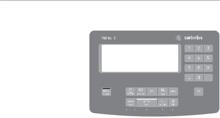
Operating elements: Midrics® 2
Input
Keypad Input
Labeled Keys
Some keys have a second function, activated by pressing and holding the key for at least 2 seconds. Whether a function is available depends on the operating state and menu settings.
eOn/standby
(in standby mode, OFF is displayed).
(– Zero the scale
– Cancel calibration/adjustment
) – Tare the scale
kToggle between 1st and 2nd weight unit, or gross and net values,
or normal and 10-fold higher resolution, depending on operating menu settings
p– To print: press briefly (< two seconds).
Midrics 2 only:
dID key for entering product information
Midrics 2 only:
IView application data or manual tare values, depending on the key pressed subsequently (e.g., ))
Midrics 2 only:
wToggle between display modes within an application program
Midrics 2 only:
OSave a value or start an application program.
Midrics 2 only:
r Modify a reference value
Midrics 2 only:
c– Quit an application or delete an input character
Midrics 2 only:
0, 1, 2 … 9
Enter numbers, letters and other characters
25

Numeric Input Through the Keypad (Midrics 2 only)
§To enter numbers (one digit at a time): Press 0, 1, 2 …9
§To save input:
press the required key (e.g., ) to save manual tare input)
§To delete a digit: Press c
Loading a Tare Value from the Weighing Platform
You can store the weight on
the weighing platform; for example, as a tare weight, by pressing
the ) key
Input Through the
Digital Input Port
You can connect a remote hand switch or foot switch to the input control line, for use with all application programs.
Assign one of the following functions to this switch in the operating menu, under “Control IO/ -> Control input":
CTRL IO
CTRL INP
 8
8
8.4 Universal IN
…
…
…
CTRL OUT
For a detailed list of menu items, please see the chapter entitled “Configuration."
26
Operating Design
1
17
16
15
14
13
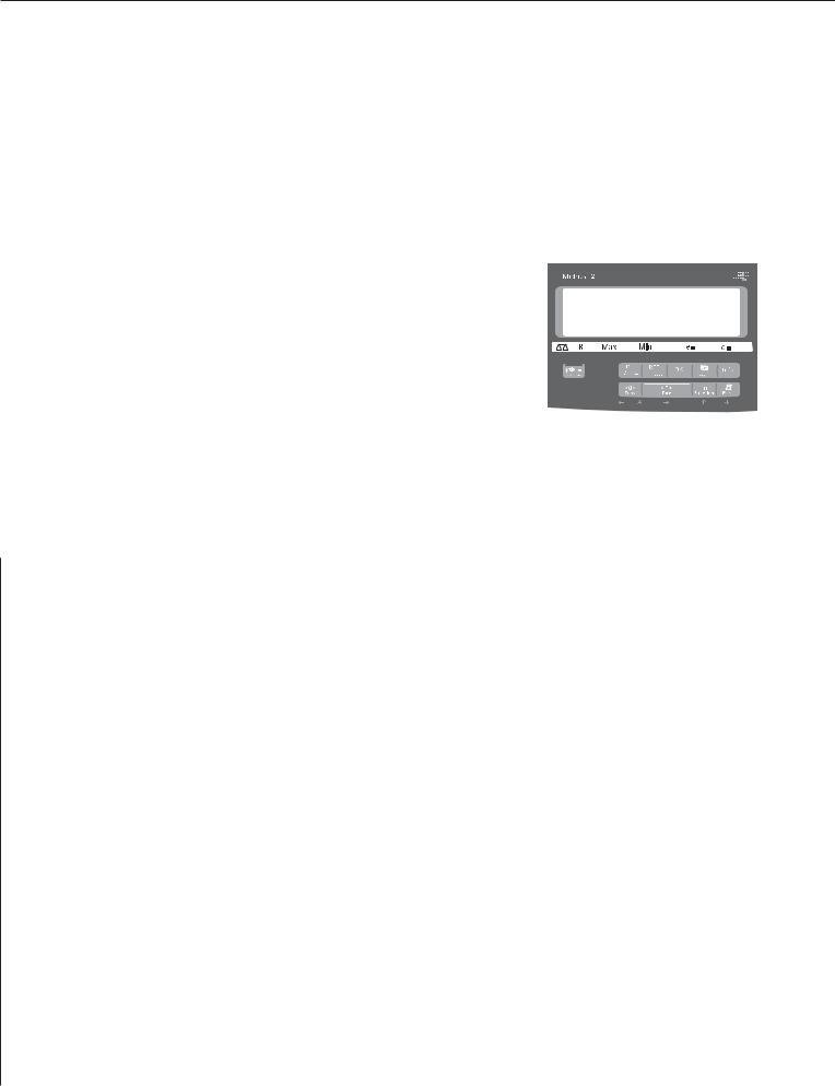
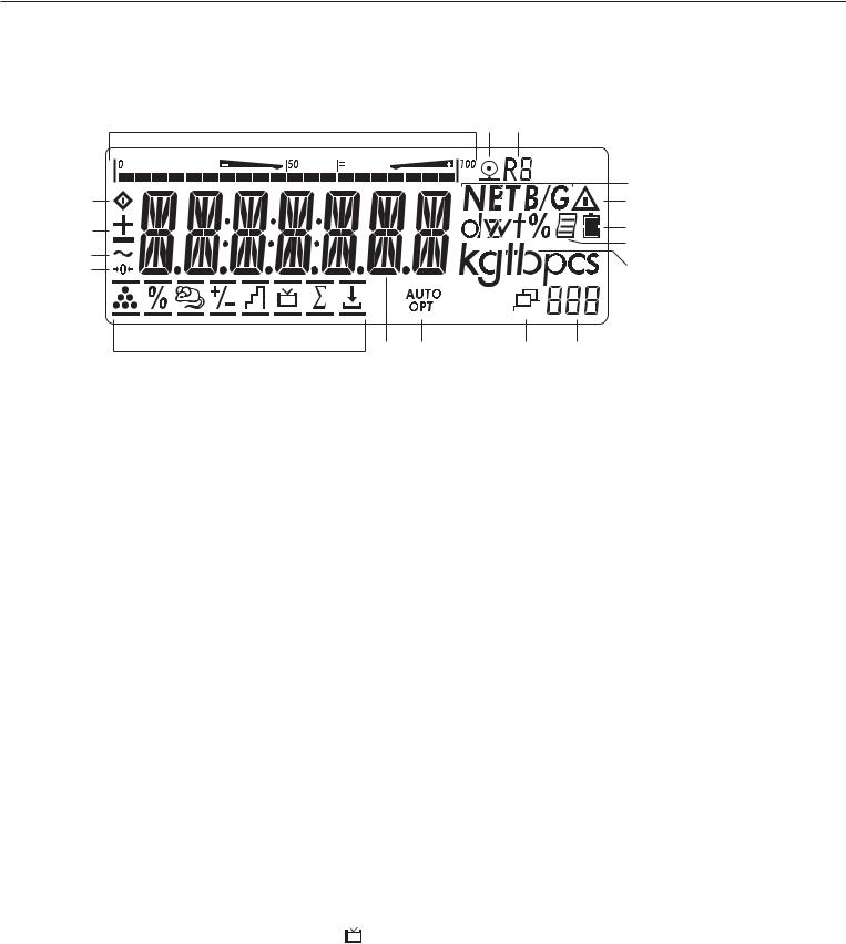
Display in Weighing Mode
The illustration above shows all display segments and the symbols and other elements used during normal weighing operation.
1.Bar graph
–Shows the percentage of the weighing platform's capacity that is “used up" by the load on the scale (gross value), or
–Shows the measured value in relation to a target value (with the Checkweighing or Classification application)
2.Printing in progress
3.Display of the range on multiple-range instruments
4.Indicates a net or gross value in
the main display (when data is stored in tare memory)
5.Identifies the value on the main display as calculated (value not valid in legal metrology)
6.Battery symbol showing status of rechargeable battery (empty outline indicates battery is drained)
7.GMP-compliant printing in progress (optional; with interface and “clock" options)
8.Weight unit of the value displayed
2 3
12 |
11 |
10 |
9 |
9.Numeric display; e.g., showing reference value (Midrics 2 only)
Midrics 2:
10.Symbol indicating data transfer:
–Interface initialized
–Flashes during data transfer
11.Symbols for reference updating (Midrics 2 only)
–Auto: Depending on the weight
value, a reaction is triggered in the application
– Opt: Automatic reference updating has been performed (Counting application)
12.Weight value or calculated value (main display)
13.Application symbols for Midrics® 2 applications:
ACounting
BWeighing in Percent
V Averaging (Animal Weighing)
HCheckweighing
WClassification
LTotalizing
RNet-total Formulation
Checkweighing towards Zero (filling to a target)
4
5
6
7
8
Verified models only:
14.The “zero-setting" symbol is displayed after the active scale or weighing platform has been zeroed
15.Stability symbol
16.Plus or minus sign for the value displayed
17.Busy symbol; indicates that an internal process is in progress
There are two display modes:
–Normal operation (weighing mode)
–Operating menu (for configuration)
Weighing Mode: Display
of Measured and Calculated
Values (Main Display)
Application, printing and battery symbols:
The application symbol indicates the selected program; for example: A Counting application symbol
SPrinting mode active
TGMP printing mode active
The battery symbol b indicates the charge level of the external rechargeable battery.
27

Bar graph
The bar graph shows the percentage of the weighing platform's capacity that is “used up" by the load on the scale (gross value).
0% |
Lower limit |
100% |
Upper limit |
The following symbols indicate tolerance levels for Checkweighing:
Bar graph with 10% markings
Minimum in Checkweighing
Target in Checkweighing
Maximum
Plus/minus sign:
+ or - for weight value or calculated value, o when the weighing platform is zeroed or tared.
Measured value/result line
This field shows weight values and calculated values (alphanumeric characters)
Unit and stability
When the weighing system reaches stability, the weight unit or the unit for a calculated value is displayed here.
Tare in memory, calculated values:
The following symbols may be displayed here:
aCalculated value (not permitted to be used in legal-for-trade applications)
NET Net value
(gross weight minus tare)
B/G Gross value
(net value plus tare)
Data in tare memory, calculated values, designation of the active weighing platform
pt Identification of manual tare input when viewing tare information
Saving Data in Weighing Mode
All of the application parameters saved (e.g., reference values) remain in memory and are still available after
–the Midrics has been switched off and back on again, or
–you return to the originally selected application from a second one (e.g., when you switch from Averaging back to Counting, all parameters saved
for Counting are available)
28
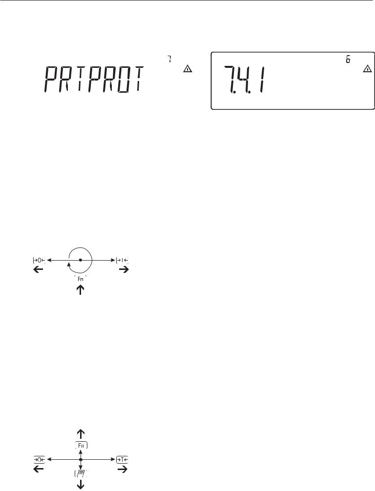
|
|
Display of menu settings: Text menu (example) |
Display of menu settings: Numeric menu (example) |
Operating Menu Navigation
The keys below the readout let you navigate the menu and define parameters for configuration.
Opening the Menu
Press the e key to switch the Midrics off and then on again; while all segments are displayed, press the ) key briefly.
Navigating the Menu
(Close the active submenu and return to the next higher menu level (“back")
) – Press briefly:
Select and save a menu item
–Press and hold (> 2 seconds): Exit the menu
kShow the next item on the same menu level (the display scrolls through all items in series)
pPrint the menu settings starting from the current position, or print Info data
Alphanumeric Input in the Menu
( – Press briefly:
Activate character to the left of the current character (when first character is active:
exit input mode without saving changes)
–Press and hold (> 2 seconds): Exit input mode without saving changes
) – Press briefly:
Confirm currently active character and move cursor 1 position to the right (after the last character: save input)
–Press and hold (> 2 sec ): Save current input and display the menu item
k– Cursor in first position, no characters entered yet:
Delete character(s) and enter 0
–Change the displayed character; scroll forward (sequence:
0 through 9, decimal point, minus sign, A to Z, space)
p – Cursor in first position,
no characters entered yet: Delete entire string and enter a space
–Change the displayed character; scroll backwards (sequence: space, Z to A, minus sign, decimal point, 9 through 0)
Numeric input in Midrics 2 operating menu:
Enter values (date and time, etc.) using the 10-key numeric keypad
Display of Menu Settings
The illustrations above show examples of the main display during menu configuration.
1Selected menu item on the text level (e.g. printer, for configuring the connected printer)
2Menu history (indicates the highest menu level)
3 Indication that there are other submenus
4 Highest level in numeric menu
5 Second level in numeric menu
6 Third level in numeric menu
Errors
–If a key is inactive, “-------" or “No function" is displayed briefly (2 seconds)
–Temporary errors are displayed for
2 seconds in the measured value/result line (e.g., Inf 09); fatal errors are displayed steadily (e.g., Err 101) until the Midrics is reset (switched off and then on again).
For a detailed description, see “Error Codes" on page 89.
Data Output
Printer
You can connect two strip or label printers to the Midrics 1 or Midrics 2 and have printouts generated at the press of a key or automatically. You can also configure separate summarized printouts, and print a list of the active menu settings. See “Configuring Printouts" on page 82 for details.
Backup
Application parameters (such as reference values) are saved when you change application programs or switch off the Midrics. You can assign a password to prevent unauthorized users from changing settings in the “Device parameters" menu under:
Setup
 Password
See also pages 31 and 48.
29
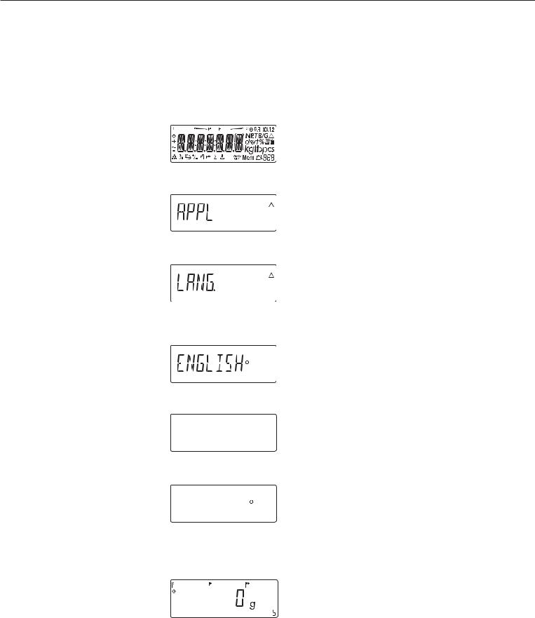
Configuration
You can configure the Midrics scale
by selecting parameters in the operating menu. The parameters are combined
in the following groups (this is the highest menu level):
–Application parameters
–Fn key function
–Device parameters (“Setup")
–Device-specific information (“Info")
–Language
When the scale is used in legal metrology, not all parameters can be accessed.
Factory-set parameters are identified by an asterisk (“*") in the list starting on page 33.
You can choose from six language settings for the display of information:
–German
–English (factory setting)
–English with U.S. date/time format
–French
–Italian
–Spanish
Printing parameter settings:
§Open the operating menu and press the p key
Scope of printout:
Depends on the active menu level Setting the Language
Setting the Language
Example: Selecting “U.S. Mode" for the language
e Switch on the scale
|
|
|
|
|
|
|
|
|
|
|
|
|
|
|
|
|
|
|
|
|
|
|
|
|
|
|
|
|
|
|
|
|
|
|
|
|
|
|
|
|
|
|
|
|
|
|
|
|
|
|
|
|
|
|
|
|
|
|
|
|
|
|
|
|
|
|
|
|
|
|
|
) |
|
|
|
|
|
|
|
|
|
|
While all segments are lit, |
||||||
|
|
|
|
|
|
|
|
|
|
|
|
|
|
|
|
|
press the ) key |
|
|
|
|
|
|
|
|
|
|
|
|
|
|
|
|
|
The first item in the main menu is shown: |
|
|
|
|
|
|
|
|
|
|
|
|
|
|
|
|
|
APPL |
k |
|
|
|
|
|
Switch to the LANG. menu item |
|||||||||||
|
|
|
|
|
|
|
|
|
|
|
|
|
|
|
|
|
(press k repeatedly until LANG. |
|
|
|
|
|
|
|
|
|
|
|
|
|
|
|
|
|
is shown) |
) |
Select LANG. to open the submenu |
|
for setting the language |
|
The currently active language setting |
|
is shown |
k |
Press k repeatedly until U.S. Mode |
|
is displayed |
U.S. Mode |
|
) |
Confirm this menu item |
U.S. Mode |
|
( |
Exit this menu level and configure |
|
other settings as desired, or |
) (press and hold) |
Exit the operating menu |
30
Loading...