


 Loading...
Ethernet TCP/IP Interface
For Rice Lake Indicators
Installation and
Configuration Manual
|
|
|
|
|
|
|
|
|
|
|
|
|
|
|
|
|
|
|
|
|
|
|
|
|
To be the best by every measure |
72117 |
|||
|
|
|
|
|
|

|
|
|
Contents |
About this Manual.................................................................................................................................... |
1 |
||
1.0 |
Introduction.................................................................................................................................. |
1 |
|
2.0 |
Installation ................................................................................................................................... |
2 |
|
|
2.1 |
Ethernet Card Installation . . . . . . . . . . . . . . . . . . . . . . . . . . . . . . . . . . . . . . . . . . . . . . . . |
. . . . . . . . . . 2 |
3.0 |
Assigning an IP Address .............................................................................................................. |
6 |
|
|
3.1 |
DeviceInstaller . . . . . . . . . . . . . . . . . . . . . . . . . . . . . . . . . . . . . . . . . . . . . . . . . . . . . . . . |
. . . . . . . . . . 6 |
|
3.2 |
Network Port Login . . . . . . . . . . . . . . . . . . . . . . . . . . . . . . . . . . . . . . . . . . . . . . . . . . . . |
. . . . . . . . . . 7 |
|
3.3 |
Command Prompt . . . . . . . . . . . . . . . . . . . . . . . . . . . . . . . . . . . . . . . . . . . . . . . . . . . . . |
. . . . . . . . . . 7 |
|
3.4 |
Configuration Parameters . . . . . . . . . . . . . . . . . . . . . . . . . . . . . . . . . . . . . . . . . . . . . . . . |
. . . . . . . . . . 8 |
4.0 |
WLAN Installation and Configuration ........................................................................................ |
10 |
|
4.1 Enclosure Disassembly. . . . . . . . . . . . . . . . . . . . . . . . . . . . . . . . . . . . . . . . . . . . . . . . . . . . . . . . . . . 11 4.2 Installing the WLAN Option Card . . . . . . . . . . . . . . . . . . . . . . . . . . . . . . . . . . . . . . . . . . . . . . . . . . . 11 4.3 Mounting the Antenna . . . . . . . . . . . . . . . . . . . . . . . . . . . . . . . . . . . . . . . . . . . . . . . . . . . . . . . . . . . 11 4.4 Wireless Configuration via Serial Mode . . . . . . . . . . . . . . . . . . . . . . . . . . . . . . . . . . . . . . . . . . . . . . . 12 4.5 Jumpers. . . . . . . . . . . . . . . . . . . . . . . . . . . . . . . . . . . . . . . . . . . . . . . . . . . . . . . . . . . . . . . . . . . . . . 12 4.6 WLAN Card Configuration . . . . . . . . . . . . . . . . . . . . . . . . . . . . . . . . . . . . . . . . . . . . . . . . . . . . . . . . 13 4.7 Enclosure Reassembly . . . . . . . . . . . . . . . . . . . . . . . . . . . . . . . . . . . . . . . . . . . . . . . . . . . . . . . . . . . 18 4.8 WiPort Wireless Specifications . . . . . . . . . . . . . . . . . . . . . . . . . . . . . . . . . . . . . . . . . . . . . . . . . . . . . 18 4.9 WiPort Technical Data . . . . . . . . . . . . . . . . . . . . . . . . . . . . . . . . . . . . . . . . . . . . . . . . . . . . . . . . . . . 19 4.10 WiPort Disclaimer . . . . . . . . . . . . . . . . . . . . . . . . . . . . . . . . . . . . . . . . . . . . . . . . . . . . . . . . . . . . . . 20
5.0 |
920i/iQube Email Setup ............................................................................................................. |
21 |
|
|
5.1 |
Configuration . . . . . . . . . . . . . . . . . . . . . . . . . . . . . . . . . . . . . . . . . . . . . . . . . . . . . . . . . . . . . . . . . . |
21 |
|
5.2 |
Troubleshooting 920i/iQube Email . . . . . . . . . . . . . . . . . . . . . . . . . . . . . . . . . . . . . . . . . . . . . . . . . . |
21 |
6.0 |
Streaming with Ethernet............................................................................................................ |
24 |
|
|
6.1 |
Serial Tunneling . . . . . . . . . . . . . . . . . . . . . . . . . . . . . . . . . . . . . . . . . . . . . . . . . . . . . . . . . . . . . . . . |
24 |
7.0 |
Ethernet Specifications ............................................................................................................. |
27 |
|
8.0 |
Appendix A................................................................................................................................. |
28 |
|
9.0 |
Glossary ..................................................................................................................................... |
29 |
|
Ethernet Interface Limited Warranty ..................................................................................................... |
32 |
||
Technical training seminars are available through Rice Lake Weighing Systems. Course descriptions and dates can be viewed at www.ricelake.com/training
or obtained by calling 715-234-9171 and asking for the training department.
© 2011 Rice Lake Weighing Systems. All rights reserved. Printed in the United States of America. Specifications subject to change without notice.
Rice Lake Weighing Systems is an ISO 9001 registered company. February 2011
i


 Rice Lake continually offers web-based video training on a growing selection of product-related topics at no cost. Visit www.ricelake.com/webinars.
ii |
Ethernet TCP/IP Card Installation Manual |

About this Manual
This manual is intended for use by service technicians responsible for installing the Ethernet card option in Rice Lake indicators.
Authorized distributors and their employees can view or download this manual from the Rice Lake Weighing Systems distributor site
at www.ricelake.com.
1.0Introduction
The Ethernet card option comes in two sizes. The larger size (PN 83267; see Figure 2-1 on page 2) can be used in the 920i, 820i, and 720i. The smaller card (PN 77142) can be used in the 820i and 720i. When ordered at the same time as the indicator, the Ethernet card can be factory installed by Rice Lake Weighing Systems if requested. Once the Ethernet option is installed, you are ready to begin configuring the scale’s IP address, gateway IP address, netmask, and Telnet configuration password.
 Important You cannot use a TCP/IP card if you are interfacing to a PLC. A PLC requires an IP card.
Rice Lake uses Lantronix Technology for most TCP/IP converters. Ensure you have the latest version of DeviceInstaller configuration software from www.lantronix.com.
General Terms and Information
ARP (Address Resolution Protocol) can be run from the Command Prompt if the MAC is known. This will assign an address to an Ethernet I/P device.
IPCONFIG from any bus will assign an IP address to an Ethernet I/P device. When entered in the Command Prompt, it will display the PC’s IP address and MAC address.
MAC (Media Access Control) is a unique number assigned by the vendor for all Ethernet devices.
Hub broadcasts all traffic to all ports, and only the correct address responds.
Switch sends data to only the correct device, keeping traffic at a minimum.
Subnet Mask is a way of splitting networks. Class A 255.0.0.0
Class B 255.255.0.0
Class C 255.255.255.0 255 Host 0 Client
|
|
|
|
|
|
|
|
|
|
|
|
|
|
|
|
|
|
|
|
|
|
|
|
|
|
Ethernet TCP/IP Card Installation Manual - Introduction |
1 |
|
|
|
|
|
2.0Installation
|
Rice lake indicators have no on/off switch. Before opening the unit, ensure the power cord is |
Warning |
disconnected from the power outlet. |
The Ethernet card should NOT be used to communicate between buildings. The Ethernet port is not |
|
|
suitable for connection to circuits used outside the building and is subject to lightning or power |
|
faults. |
Caution |
Use a wrist strap to ground yourself and protect components from electrostatic discharge (ESD) |
when working inside the indicator enclosure. |
|
|
This unit uses double pole/neutral fusing which could create an electric shock hazard. Procedures |
|
requiring work inside the indicators must be performed by qualified service personnel only. |
The indicator enclosure must be opened to install the Ethernet card.
|
Assembly |
|
|
|
|
|
|
|
|
|
EGnd |
|
|
|
|
|
|
|
|
C2 |
C1 |
|
RxD- |
|
|
|
P/N Revision |
|
|
|
|
|
|
|
|
|||
|
83267-A |
|
|
|
|
|
1 C4 |
|
C3 |
|
RxD+ |
|
J1 |
|
|
|
|
|
|
J2 |
U1 |
C5 |
|
TxD- |
|
|
|
|
|
|
|
|
|
|
|
TxD+ |
|
|
|
33 |
Aux+5V |
Gnd |
Gnd |
232-Rx |
232-Tx |
|
|
|
|
|
|
|
|
|
|
|
EGnd |
|
||||||
|
|
|
|
|
|
|
||||||
|
|
|
|
|
J4 |
1 |
|
|||||
|
|
|
|
|
|
|
|
|
|
1 |
RJ-45 Connector |
|
|
|
|
|
|
|
|
|
|
|
|
||
|
|
|
|
|
|
|
|
|
|
|
|
|
|
JP1 |
TP1 |
|
C6 |
TP5 |
TP6 |
TP7 |
TP8 |
|
|
|
|
|
|
|
|
|
|
|
|
|||||
|
+5V |
|
|
|
|
|
|
|
J3 |
|
8 |
|
|
TP2 |
|
VR1 |
|
|
|
|
|
||||
|
|
|
|
|
|
|
|
|||||
|
INPUT |
|
|
|
|
|
|
|
1 |
|||
|
|
|
|
|
|
|
|
|
|
|
||
|
TP3 |
|
|
|
|
|
|
|
|
|
|
|
|
|
|
|
|
|
|
|
|
|
|
|
|
|
+6V |
TP4 |
|
|
|
|
|
|
|
|
8 |
|
|
|
|
|
|
|
|
|
|
|
|
||
|
TP9 |
|
|
C7 |
|
|
|
|
LX1 |
|
|
|
|
C8 |
|
|
|
|
|
|
|
|
|
1 |
|
|
|
|
|
|
|
|
|
|
|
|
1-TX+ |
|
|
|
|
|
|
|
|
|
|
|
|
|
|
|
|
U2 |
|
|
|
|
|
|
|
|
|
2-Tx- |
|
|
|
|
|
|
|
|
|
|
|
3-Rx+ |
|
|
|
|
|
|
|
|
|
|
|
|
|
|
|
1 |
|
|
|
|
|
|
|
|
|
|
6-Rx- |
|
|
|
|
|
|
|
|
|
|
|
7-SHLD |
|
|
MANUAL |
|
|
|
|
|
|
|
|
|
|
|
D |
RESET |
|
|
|
|
|
|
|
|
|
8 |
|
L |
|
|
GND |
|
|
|
|
|
|
|
||
D |
SW1 |
|
|
|
|
|
|
|
|
|
|
|
2004 |
|
|
|
|
|
|
|
|
|
|
|
|
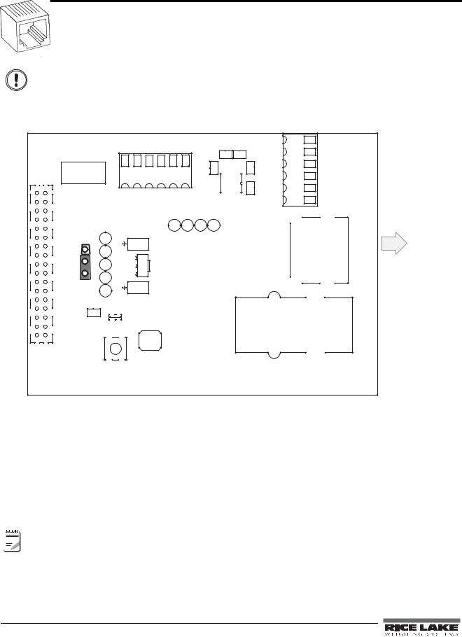
Figure 2-1. Ethernet Interface Card
2.1Ethernet Card Installation
1.Disconnect the indicator from power source.
2.Place indicator on an antistatic work mat. Remove screws that hold the cover to the enclosure body, then lift the cover away from the enclosure and set it aside.
3.Remove plug from cord grip on the indicator that will be used to run the Ethernet cabling.
4.Carefully align the option card connector with the connector on the indicator’s CPU board. Press down to seat the option card in the CPU connector.

 Note Refer to the indicator manual for exact pin locations.
5.Use the screws provided in the option kit to secure the other end of the option card to the threaded standoffs on the indicator’s CPU board.
6.Ensure jumper JP1 on the Ethernet card is in the +6V position for installation.
2Ethernet TCP/IP Card Installation Manual
|
|
|
T |
|
|
E |
|
|
S |
|
|
E |
|
|
|
R |
|
|
1 |
|
|
|
|
|
W |
||
S |
|
|
|
Diagnostic Lights
Patch cable
(Only use if terminating Ethernet cable to J4 screw terminals) 

LX1
J3 |
|
|
|
EGnd |
|
|
|
TxD+ |
- |
|
|
TxD |
+ |
|
|
|
RxD |
- |
|
|
|
RxD |
|
|
|
|
EGnd |
J1
J2
J4
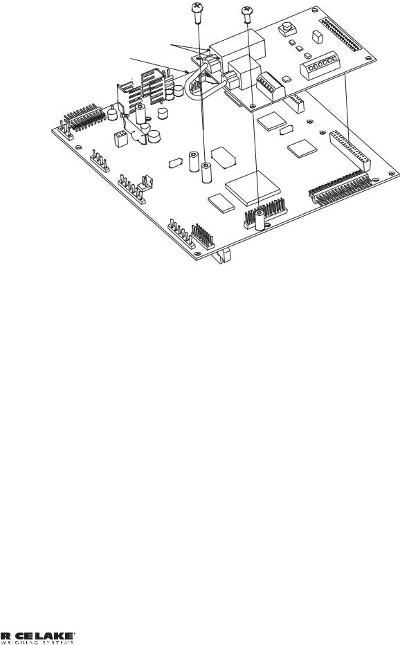
Figure 2-2. Ethernet Card Installation onto 920 CPU Board
2.1.1Ethernet Card Serial Port Wiring
The Ethernet card requires an RS-232 communications connection to the Rice Lake indicator. The indicator and Ethernet card must be set to the same baud rate (Rice Lake indicators’ default serial baud rate is 9600.) To change the Ethernet card baud rates, refer to the Lantronix User’s Guide.
1.To attach the 6-inch, unshielded cable directly to the 920i, remove the serial connector from the CPU board (port 1, 3, or 4).
2.Use the supplied 60-inch, unshielded cable to run from J2 on the Ethernet board to the connector of choice. Refer to the tables on the following page for pin assignments.
3.Once cables are attached, plug the connector into the header on the board. Table 2-1 shows the Ethernet card serial port pin assignments.
Pin |
Signal |
|
|
1 |
Txd |
|
|
2 |
Rxd |
|
|
3 |
Gnd |
|
|
4, 5, or 6 |
Not used |
|
|
Table 2-1. Ethernet Card J2 Pin Assignment
|
|
|
|
|
|
|
|
|
|
|
|
|
|
|
|
|
|
|
|
|
|
|
|
|
|
Ethernet TCP/IP Card Installation Manual - Installation |
3 |
|
|
|
|
|

.
920i
Connector |
Pin |
|
Signal |
Port |
|
|
|
|
|
J11 |
1 |
|
Gnd |
1 |
|
|
|
|
|
|
2 |
|
RS-232 RxD |
|
|
|
|
|
|
|
3 |
|
RS-232 TxD |
|
|
|
|
|
|
J9 |
1 |
|
GnD |
3 |
|
|
|
|
|
|
2 |
|
RS-232 RxD |
|
|
|
|
|
|
|
3 |
|
Rs-232 TxD |
|
|
|
|
|
|
J10 |
1 |
|
GnD |
4 |
|
|
|
|
|
|
2 |
|
RS-232 RxD |
|
|
|
|
|
|
|
3 |
|
RS-232 TxD |
|
|
|
|
|
|
|
|
820i |
|
|
|
|
|
|
|
Connector |
Pin |
|
Signal |
Port |
|
|
|
|
|
J9 |
1 |
|
CLK |
1 |
|
|
|
|
|
|
2 |
|
+5V |
|
|
|
|
|
|
|
3 |
|
GND |
|
|
|
|
|
|
|
4 |
|
DATA |
|
|
|
|
|
|
|
|
|
|
|
J10 |
1 |
|
GND |
2 |
|
|
|
|
|
|
2 |
|
RS-232 RxD |
|
|
|
|
|
|
|
3 |
|
RS-232 TxD |
|
|
|
|
|
|
|
4 |
|
RS-232 RTS |
|
|
|
|
|
|
|
5 |
|
RS-232 CTS |
|
|
|
|
|
|
|
6 |
|
GND |
|
|
|
|
|
|
|
|
|
|
|
J11 |
1 |
|
GND |
4 |
|
|
|
|
|
|
2 |
|
N/C |
|
|
|
|
|
|
|
3 |
|
N/C |
|
|
|
|
|
|
|
4 |
|
RS-485 A |
|
|
|
|
|
|
|
5 |
|
RS-485 B |
|
|
|
|
|
|
|
6 |
|
+20mA OUT |
|
|
|
|
|
|
|
7 |
|
–20mA OUT |
|
|
|
|
|
|
|
8 |
|
GND |
|
|
|
|
|
|
|
9 |
|
RS-232 RxD |
|
|
|
|
|
|
|
10 |
|
RS-232 TxD |
|
|
|
|
|
|
Table 2-2. 920 and 820 Serial Port Pin Assignments
720i
Connector |
Pin |
Signal |
Port |
|
|
|
|
J3 |
1 |
CLK |
1 |
|
|
|
|
|
2 |
+5V |
|
|
|
|
|
|
3 |
GND |
|
|
|
|
|
|
4 |
DATA |
|
|
|
|
|
|
|
|
|
J2 |
1 |
GND |
2 |
|
|
|
|
|
2 |
RS-232 RxD |
|
|
|
|
|
|
3 |
RS-232 TxD |
|
|
|
|
|
|
4 |
RS-232 RTS |
|
|
|
|
|
|
5 |
RS-232 CTS |
|
|
|
|
|
|
6 |
GND |
|
|
|
|
|
|
|
|
|
J4 |
1 |
RS-422/485 |
3 |
|
|
Y |
|
|
|
|
|
|
2 |
RS-422/485 |
|
|
|
Z |
|
|
|
|
|
|
3 |
RS-422/485 |
|
|
|
B |
|
|
|
|
|
|
4 |
RS-422/485 |
|
|
|
A |
|
|
|
|
|
|
5 |
+6V |
|
|
|
|
|
|
6 |
GND |
|
|
|
|
|
|
|
|
|
J5 |
1 |
GND |
4 |
|
|
|
|
|
2 |
RS-232 RxD |
|
|
|
|
|
|
3 |
RS-232 TxD |
|
|
|
|
|
|
4 |
20mA OUT |
|
|
|
|
|
Table 2-3. 720 Serial Port Pin Assignments
Connector |
Pin |
Signal |
|
|
|
J5 |
1 |
EDP TxD |
|
|
|
|
2 |
GND |
|
|
|
|
3 |
EDP RxD |
|
|
|
|
4 |
Printer TxD |
|
|
|
|
5 |
Printer RxD |
|
|
|
|
6 |
–20 mA TxD |
|
|
|
|
7 |
+20 mA TxD |
|
|
|
|
8 |
RS-485A |
|
|
|
|
9 |
RS-485B |
|
|
|
|
10 |
GND |
|
|
|
Table 2-4. 520 Serial Port Pin Assignments
4Ethernet TCP/IP Card Installation Manual
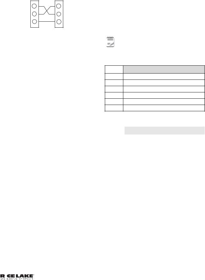
Ethernet |
Indicator |
Card |
Port |
TXD |
TXD |
RXD |
RXD |
GND |
GND |
Figure 2-3. Ethernet Card Serial Wiring
4.Use cable ties to secure loose cables inside the enclosure away from high voltage circuits
2.1.2External Ethernet Cabling
Configure external Ethernet cabling using either the RJ-45 connector (LX1) or the hardwire connection to J4 on the Ethernet card. When using an external RJ-45 connector, we recommend using a DNET 1 network surge suppressor (PN 72682) wired through a cord grip with the RJ-45 socket left outside of the enclosure.
Pin |
Signal |
|
|
1 |
Gnd |
|
|
2 |
TxD+ |
|
|
3 |
TxD- |
|
|
4 |
RxD+ |
|
|
5 |
RxD- |
|
|
6 |
Gnd |
|
|
Table 2-5. Ethernet Card J4 Pin Assignment
2.1.3Reassembling The Enclosure
1.Once cabling is complete, position the backplate over the enclosure and reinstall the backplate screws. Use the torque pattern provided in the indicator’s installation manual to prevent distorting the backplate gasket.
2.Ensure no excess cable is left inside the enclosure and tighten the cord grips.
3.Reconnect power to the indicator.

 Note Contact factory for washdown option.
2.1.4Ethernet Option Parts Kit Contents
Table 5-4 shows the parts kit contents for PN 71986.
PN |
Description |
|
|
14822 Screws, 4-40NCx1/4 (2)
15631 Cable tie, 3 in nylon (2)
54325 Unshielded cable, grey 60 in (1)
78269 RJ-45 cable, 5 in (1)
83267 Ethernet card, RS-232/Ethernet (1)
72763 Ethernet CD (1)
Table 2-6. PN 71986 Parts Kit Contents shows the parts kit contents for PN 77205.
PN |
Description |
|
|
14822 |
Screws, 4-40NCx1/4 (2) |
|
|
15631 |
Cable tie, 3 in nylon (2) |
|
|
54325 |
Unshielded cable, grey 60 in (1) |
|
|
78269 |
RJ-45 cable, 5 in (1) |
|
|
72696 |
Cable, 3-pin to blunt 3-wire (1) |
|
|
83267 |
Ethernet card, RS-232/Ethernet (1) |
|
|
72763 |
Ethernet CD (1) |
|
|
Table 2-7. PN 77205 Parts Kit Contents
|
|
|
|
|
|
|
|
|
|
|
|
|
|
|
|
|
|
|
|
|
|
|
|
|
|
Ethernet TCP/IP Card Installation Manual - Installation |
5 |
|
|
|
|
|
3.0Assigning an IP Address
The following section covers the steps required to assign an IP address. The IP address must be assigned and configured before a network connection is available. There are four methods, any one of which can be used:
•Lantronix® DeviceInstallerTM
•Network port login
•Command Prompt
•Web Configuration
Both of these installer tools are located on the Ethernet Configuration CD, PN 72763.
Refer to www.lantronix.com to ensure you have the most up-to-date version of DeviceInstaller.

 Note If connecting from a PC to the Ethernet card, use a crossover cable. Otherwise, use a straight through
cable if connecting via a network.
Refer to the Lantronix User’s Guide found on the Ethernet Configuration CD for further information on the Ethernet configuration procedures.
3.1DeviceInstaller
DeviceInstaller provides the preferred method for setting up an IP address for the Ethernet card with Rice Lake indicators. Depending on firewall restrictions and other network variables, however, DeviceInstaller may not be able to find the Ethernet card. If you encounter troubles in using the instructions listed in this section, use the Windows Command Prompt (Section 3.3 on page 7), which will always work regardless of network variables.
The DeviceInstaller runs on a personal computer to help assign an IP address. To use the DeviceInstaller, use the following steps:
1.Insert the Ethernet Configuration CD into the hard drive of your PC running Windows® 95, 98, ME, 2000, or XP.
2.Install DeviceInstaller per on-screen instructions.
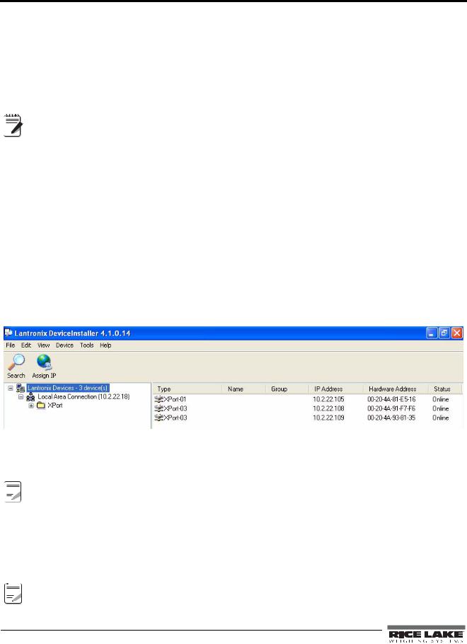
3.Start the DeviceInstaller program and follow the on screen instructions.
Figure 3-1. DeviceInstaller Main Menu Screen
Rice Lake indicators come supplied with a pre-configured IP address which automatically enables Dynamic Host Control Protocol (DHCP)—It is recommended that you assign a static IP address to your card for use in the field.


 The web connection to the Ethernet card requires the original JAVA by Sun Microsystems. For a free
 Note download, go to www.JAVA.com
4.Click Action / Assign IP Address to assign a new IP address.
5.Enter the hardware address found on LX1.
6.It is recommended that you assign your own IP address to the card. Enter a chosen IP address in the Enter IP field. Record the configured IP address for future reference.
7.Press Set IP to assign a new IP address.


 The DeviceInstaller will search the network to see if the proposed IP address is already being used. If it is
 Note already in use, on the network, the operation will fail.
6 Ethernet TCP/IP Card Installation Manual

3.2Network Port Login
The network port login provides a way to make a telnet connection to the network port (9999). This ARP method is available under UNIX and Windows-based systems.
1.Set a static ARP with the desired IP address using the hardware address of the scale. The address is printed on a label attached to the Ethernet card.
|
In order for the ARP command to work in Windows®, the ARP table on the PC must have at least |
Note |
one IP address defined other than its own. Type “ARP - A” at the DOS prompt (or from Run) to |
|
verify that there is at least one entry in the ARP table. If there is no entry other than the local |
|
machine, ping another IP machine on your network to build the ARP table. This has to be a host |
|
other than the machine on which you are working. Once there is at least one entry in the ARP |
table, use the following commands to ARP an IP address to the scale. arp –s 128.1.123.123.00.20-4a-xx-xx-xx
2.Open a Telnet connection to port 1 by clicking the Telnet icon on the Toolbar. The connection will fail quickly but the device server temporarily changes its IP address to the one designated in this step and sets all required parameters.
Telnet 128.1.123.123.1
3.Open a Telnet connection to port 9999 and press the ENTER key within three seconds to go into the Setup mode. if you wait longer than three seconds, the unit will reboot. Set all required parameters.
Telnet 128.1.123.123.9999
Note |
The IP address you just entered is temporary and will revert to the default when the unit’s power |
|
is reset unless you log into the unit and store the changes permanently. |
3.3Command Prompt
As an alternative to DeviceInstaller, you can use the Windows Command Prompt to set the IP address of the Ethernet card. Command Prompt can be opened by selecting Start » Run and typing cmd.
It is also located in Start » Programs » Accessories » Command Prompt.
1. From Command Prompt, type arp and press Enter to see a list of available commands.
Figure 3-2. Available ARP Commands.
|
|
|
|
|
|
|
|
|
|
|
|
|
|
|
|
|
|
|
|
|
|
|
|
|
|
Ethernet TCP/IP Card Installation Manual - Assigning an IP Address |
7 |
|
|
|
|
|
2.To statically enter the IP address, type arp-s (your IP address) (mac address shown on the card). Refer to the first example shown in Figure 3-2 7.
3.Use a telnet session to activate the address by typing telnet (your IP address) 1. The telnet connection will time out and fail, but the address will be activated.
4.You can view the address in your arp table by typing arp -a.
This will list the arp table and you will see your IP address and its mac address, and it will be listed as a static entry.
5.You should now be connected and can test connectivity by pinging your address. To ping your address, type ping (your IP address).
6.Now that you have statically established communication on your local machine, you will be able to search and find the card with DeviceInstaller to set the permanent IP address of the card.
If you are having connection issues, there may be network variables preventing communication. Make 


 Note sure to turn off all firewalls, anti-virus software, and be logged in as a user with administrator privileges.
Other methods of configuring the settings on the card are vie the web or a telnet session. You can see the card’s settings through your web browser by typing its IP address in the address bar of Internet Explorer.
The card be configured via telnet by typing telnet (your IP address) 9999.
When using telnet, the numbers after the IP address stand for the port number. Port 9999 “talks” to the card (used for configuring the card only). Port 10001 “talks” through the card to the indicator (used for communicating with iRev, Revolution, HyperTerminal, etc.).
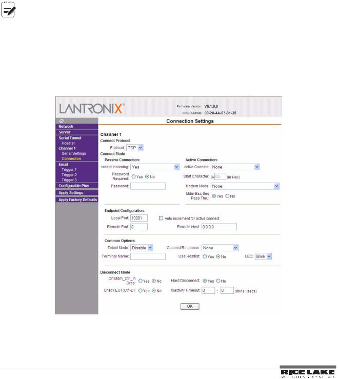
3.4Configuration Parameters
Web configuration of the card can be done by entering the IP address in your web browser and clicking GO (or pressing Enter). This allows changing any or all setup in the Ethernet option card.
Figure 3-3. Web Configuration Connection Settings
8 Ethernet TCP/IP Card Installation Manual
Loading...