


Ishida IGX IGB
86547
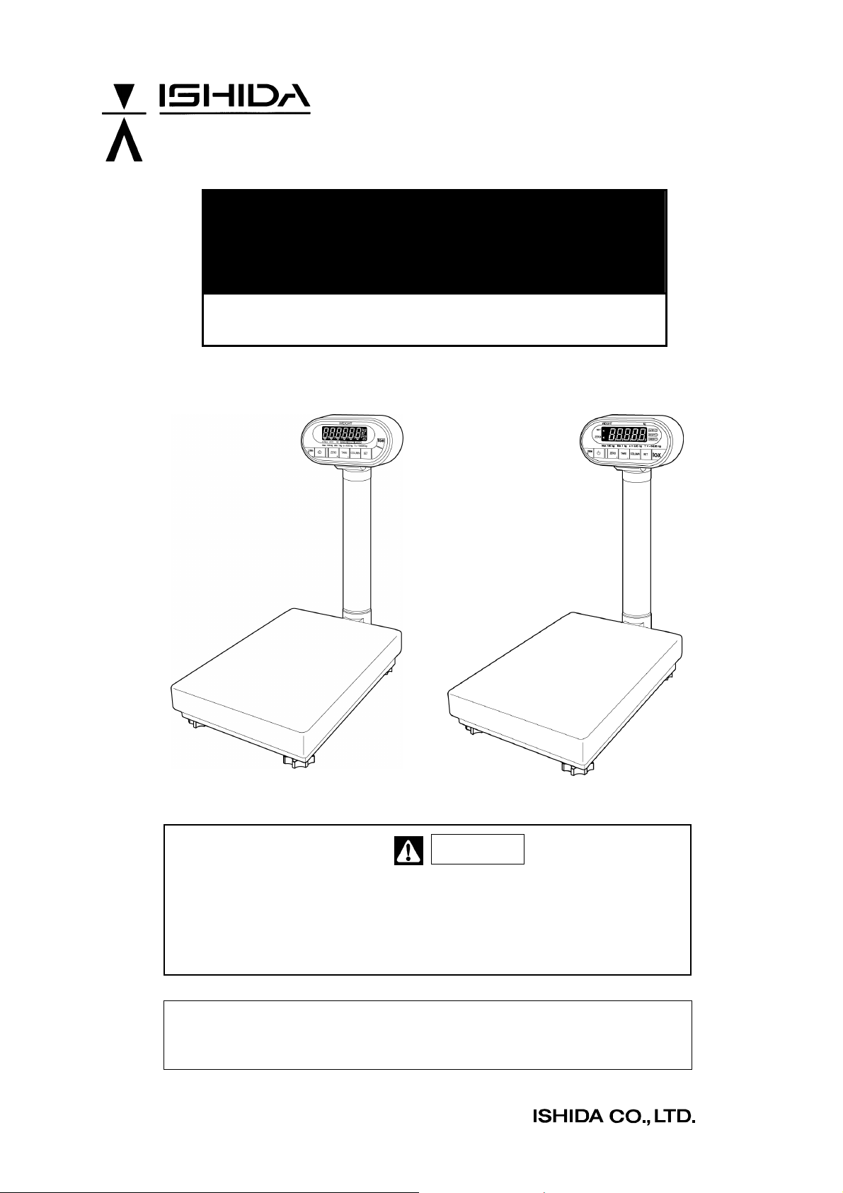
IGB/IGX Series
(Overseas Specifications)
Service Manual
The First Edition
IGB Series IGX Series
Read this manual thoroughly and do not perform installation, operation,
maintenance, or inspection unless you fully understand all of the contents.
Keep this manual in a safe place where you can refer to it easily while
installing, operating, and carrying out maintenance or inspections.
This manual is for use by service personnel of our company or qualified to
perform maintenance services for this machine. Use by anyone except the
above personnel is not permitted.
Manual No. 085-3435-07
Warning

CONTENTS
CHAPTER 1. PRODUCT OVERVIEW ..................................................................................................3
1.1 Machine Outline.............................................................................................................................3
1.2 Standard Specifications .................................................................................................................3
1.3 Appearance ...................................................................................................................................5
1.4 Display Unit ...................................................................................................................................6
1.5 Outer Dimensions..........................................................................................................................7
CHAPTER 2 TEST MODE.....................................................................................................................9
2.1 Operation.......................................................................................................................................9
2.1.1 Starting Each Mode ................................................................................................................9
2.1.2 Ending Test Mode...................................................................................................................9
2.1.3 Test Mode Flow ....................................................................................................................10
2.1.4 Key Functions.......................................................................................................................10
2.1.5 Mode List..............................................................................................................................11
2.2 C1 Mode (Country No., Scale No., Zero point, Span adjustment)................................................12
2.2.1 Country No. Table.................................................................................................................12
2.2.2 Scale No. Table ....................................................................................................................13
2.2.3 Operation Procedure ............................................................................................................14
2.3 C2 Mode: Key Check...................................................................................................................18
2.4 C3 Mode: Display Check 1 (Simplified Check) ............................................................................18
2.5 C4 Mode: Display Check 2 (Detailed Check)...............................................................................19
2.6 C5 Mode: Program No Display ....................................................................................................19
2.7 C6 Mode: RAM Clear and E2ROM Clear ....................................................................................20
2.8 C7 Mode: Weighing Condition Setting.........................................................................................21
2.9 C8 Mode: E2ROM Data Reading.................................................................................................24
2.10 C9 Mode: Board Inspection (A/D Check, I/F Check)....................................................................26
CHAPTER 3 HARDWARE CONFIGURATION ...................................................................................27
3.1 Mechanical Parts .........................................................................................................................27
3.1.1 Load Cell ..............................................................................................................................30
3.2 Electric Parts (IGB Series)...........................................................................................................31
3.2.1 IGB Block Diagram ...............................................................................................................31
3.2.2 Main Board (PS-018)............................................................................................................32
3.2.3 Power Board (PS-019) .........................................................................................................33
3.3 Electric Parts (IGX Series)...........................................................................................................34
3.3.1 IGX Block Diagram ...............................................................................................................34
3.3.2 Main Board (PS-016)............................................................................................................35
CHAPTER 4 MAINTENANCE .............................................................................................................37
4.1 Disassembly Procedure for Display Unit......................................................................................37
4.2 Replacement of Main Board ........................................................................................................38
4.2.1 IGB Series ............................................................................................................................38
4.2.2 IGX Series ............................................................................................................................39
4.3 Replacing and Adjusting Load Cell ..............................................................................................41
4.3.1 Checking and Adjusting Gap of Four-corner Limit ................................................................42
4.3.2 Performing Zero Point and Span Adjustments......................................................................43
4.4 Troubleshooting ...........................................................................................................................44
Manual No. 085-3435-07 1/45 IGB/IGX Series (Overseas Specifications) Service Manual
OUTLINE
• Purpose of this manual
• This manual is to be used as a reference for the maintenance servicing of IGB or IGX series.
• Related manual
• For placing the product, mounting the display pole, setup mode and setup values, refer to the
operation manual.
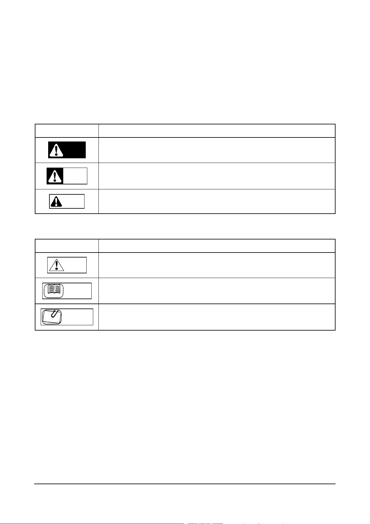
• Symbols in the description
1. Warning symbols
Symbol Meaning
Danger
Warning
Caution
Indicates information that, if not heeded, is likely to result in loss of life or serious
injury.
Indicates information that, if not heeded, may result in loss of life or serious
injury.
Indicates information that, if not heeded, could result in relatively serious injury,
damage to the machine or faulty operation.
2. Explanatory symbols
Symbol Meaning
Note
Indicates additional information of particular importance.
Reference
Information
Reference
Information
Indicates a page to refer to.
Indicates information to help you understand the related text.
• Readers of this manual
This manual is designated for use by servicing personnel. Use by other personnel is not permitted.
• This manual may be revised in accordance with modifications to the machine.
• All rights are reserved. Copying any part of this manual is prohibited without the permission of Ishida.
Manual No. 085-3435-07 2/45 IGB/IGX Series (Overseas Specifications) Service Manual
Chapter 1. Product Overview
1.1 Machine Outline
• The base of software used is the same as that of the IGB and IGX Series. Therefore, the Setup and
Test mode items are same as those of the IGB and IGX Series. The machine functions are available
within these standard specifications.
• A check function of the upper and lower weight limits are standardly provided with the IGB and IGX
Series.
• The main board is different from that of the IGB and IGX Series. However, basic operations are same
for these models.
• For the IGB Series, an LCD is adopted, and either two dry batteries or an AC adapter can be used as a
power source.
• For the IGX Series, a VFD is adopted, and a wide selection of power sources ranging from 100 VAC to
240 VAC is available.
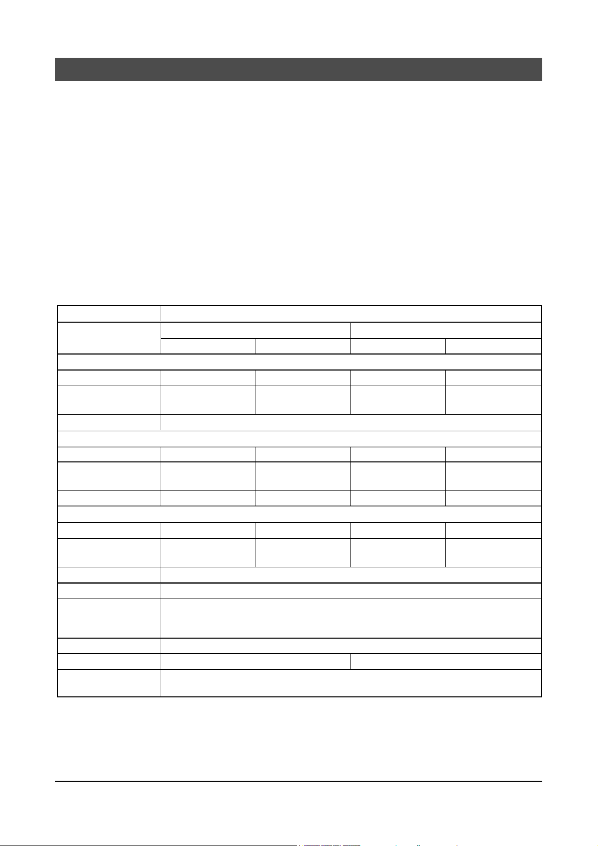
1.2 Standard Specifications
Item Contents
Model Name
OIML R76 Class III
Weighing Capacity 60kg 150kg 60kg 150kg
Graduation 0.02kg 0.05kg 0.02kg 0.05kg
Accuracy 1/3000
Non-OIML (ASIA)
Weighing Capacity 60kg 150kg 60kg 150kg
Graduation 0.01kg 0.02kg 0.01kg 0.02kg
Accuracy 1/6000 1/7500 1/6000 1/7500
lb/kg Switching Specification (USA)
Weighing Capacity 150lb/60kg 300lb/150kg 150lb/60kg 300lb/150kg
Graduation 0.05lb/0.02kg 0.1lb/0.05kg 0.05lb/0.02kg 0.1lb/0.05kg
Accuracy 1/3000
Weighing Platter 550mm (L) x 400mm (W)
Exterior Material
Display Angle Adjust Angle adjustable from the horizon (0°) to the front, Knob locking method
Weight 16.0kg (excluding batteries) 16.8kg
Environmental
Condition
IGB-60 IGB-150 IGX-60 IGX-150
Display: ABS resins
Display pole: Aluminum die-cast
Weighing platter: Stainless (SUS304)
Temperature from -5°C to +40°C, Relative humidity 80%RH (max.) without condensation
IGB Series IGX Series
Manual No. 085-3435-07 3/45 IGB/IGX Series (Overseas Specifications) Service Manual
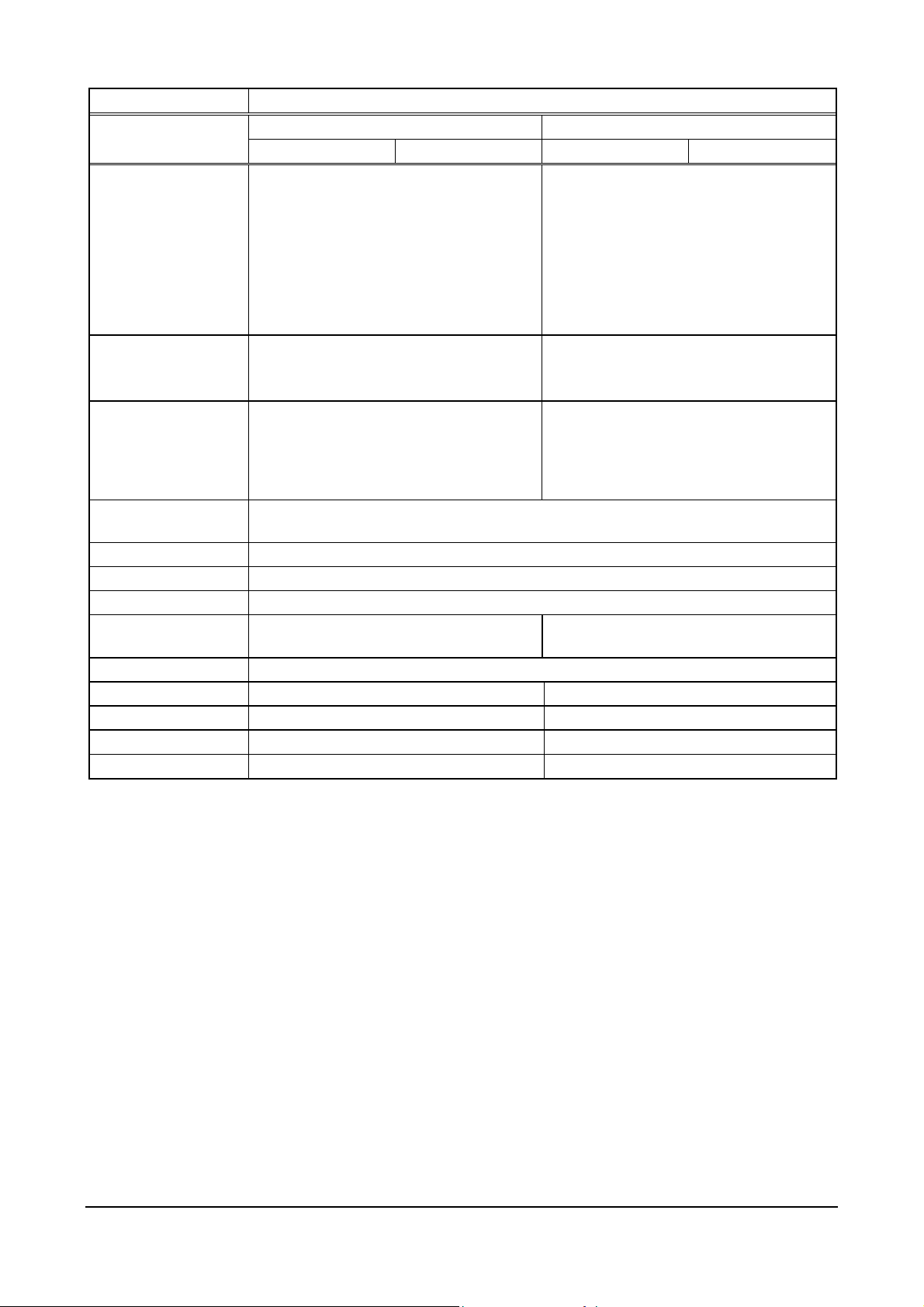
Item Contents
Model Name
Power Source
Power Consumption 25mA
Display LCD
Tare Subtraction Key-in tare
Preset Function [Program Mode] 10 PLUs from PLU 1 to PLU 10 (Tare weight, Upper limit, Lower limit)
Upper Limit Range More than the lower limit, within 5 digits (99999)
Lower Limit Range Less than the upper limit, (5 digits in case of the upper limit = 0)
Auto Power Off [Setup Mode] None/10min./ 20min./ 30min./
Auto Preset Call-up [Setup Mode] Function “Yes”/”No” selection (PLU 1 is called up when the power is ON.)
Battery Check Mode Yes No
Buzzer No [Setup Mode]
ON/OFF Switch No [Setup Mode]
Option AC adapter (Dealer option)
IGB-60 IGB-150 IGX-60 IGX-150
Two dry batteries (not included with the
machine), or optional AC adapter
[Battery Life]
Conditions: No option, Temperature 20°C,
Relative humidity 60%RH
Two “D” size alkaline batteries (Approx. 500H
continuous use)
Numerics: 6 digits, Height 25mm
Mark: Battery. Zero point, Now subtracting
tare, Stable, Weight unit (kg・lb), Over,
Under, Accept
Preset tare
40min./ 50min./ 60min.
IGB Series IGX Series
The required transformer is provided for
each 100VAC, 120VAC, 220VAC, or
240VAC.
100VAC: 57mA
120VAC: 46mA
220VAC: 28mA
240VAC: 23mA
VFD
Numerics: 5 + 1/2 digits, Height 29mm
Mark: Zero point, Now subtracting tare
LED
Over, Under, Accept
No
Manual No. 085-3435-07 4/45 IGB/IGX Series (Overseas Specifications) Service Manual
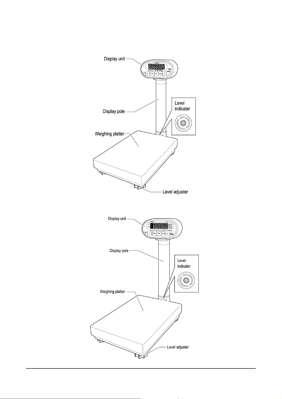
1.3 Appearance
IGB Series (Asia/Oceania Specification)
IGX Series (Asia/Oceania Specification)
Manual No. 085-3435-07 5/45 IGB/IGX Series (Overseas Specifications) Service Manual
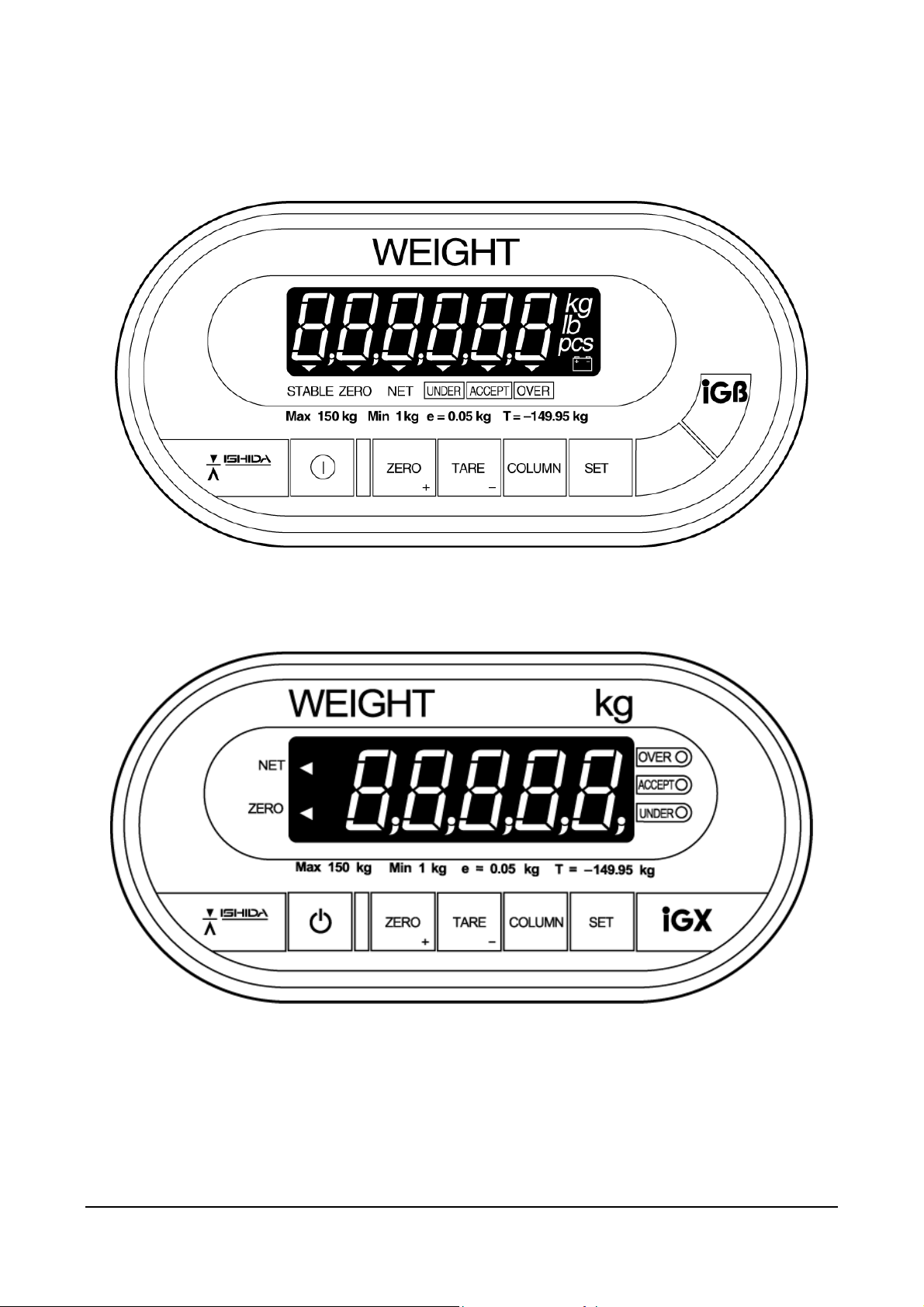
1.4 Display Unit
IGB Series (Asia/Oceania Specification)
IGX Series (Asia/Oceania Specification)
Manual No. 085-3435-07 6/45 IGB/IGX Series (Overseas Specifications) Service Manual
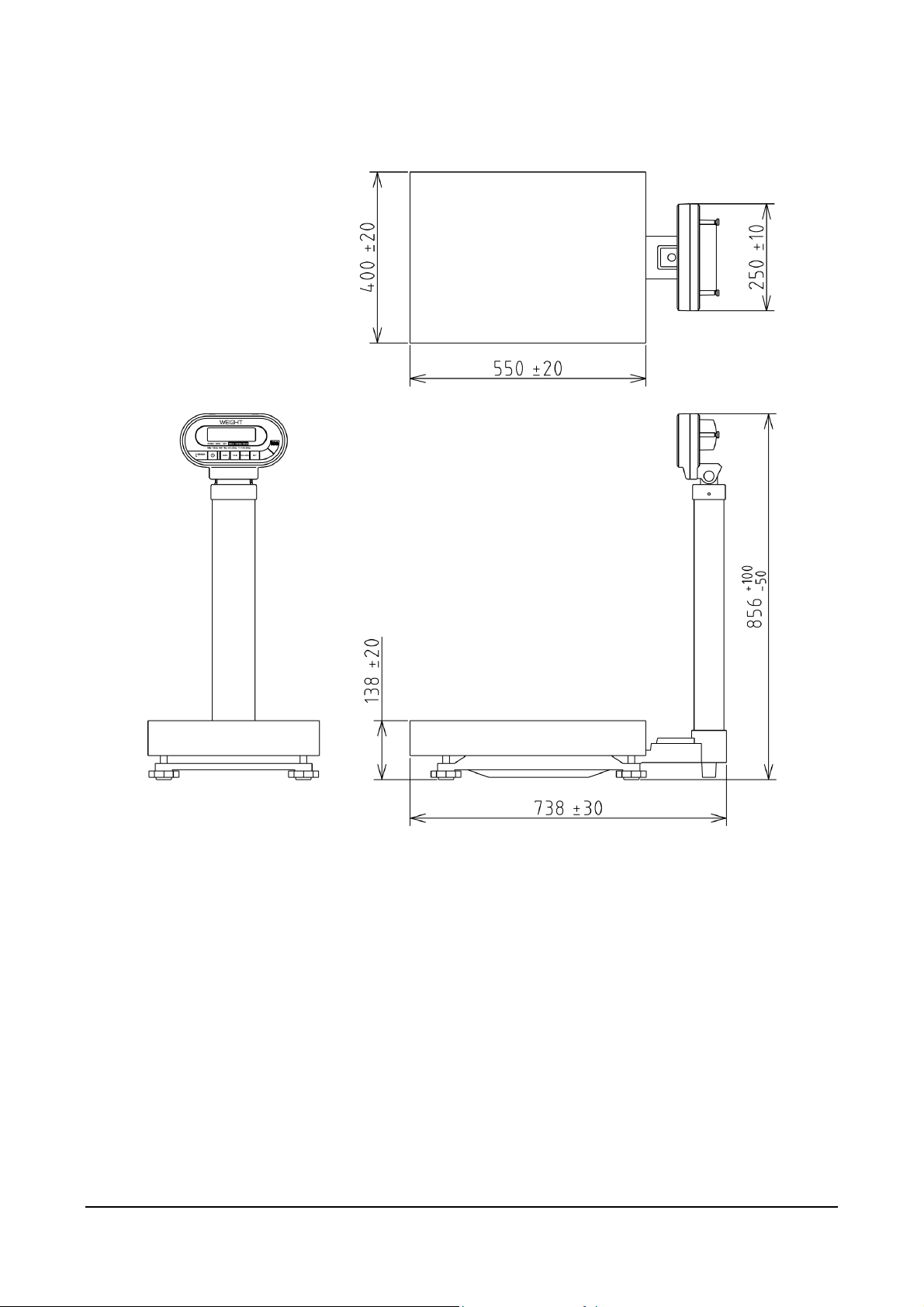
1.5 Outer Dimensions
(Unit: mm)
Manual No. 085-3435-07 7/45 IGB/IGX Series (Overseas Specifications) Service Manual

memo
Manual No. 085-3435-07 8/45 IGB/IGX Series (Overseas Specifications) Service Manual
Chapter 2 Test Mode
The Test Mode is used to check the machine when maintenance is performed or to perform settings.
2.1 Operation
The keys used in the following diagram are for Asia/Oceania specifications. For specifications for other
countries, use the corresponding keys.
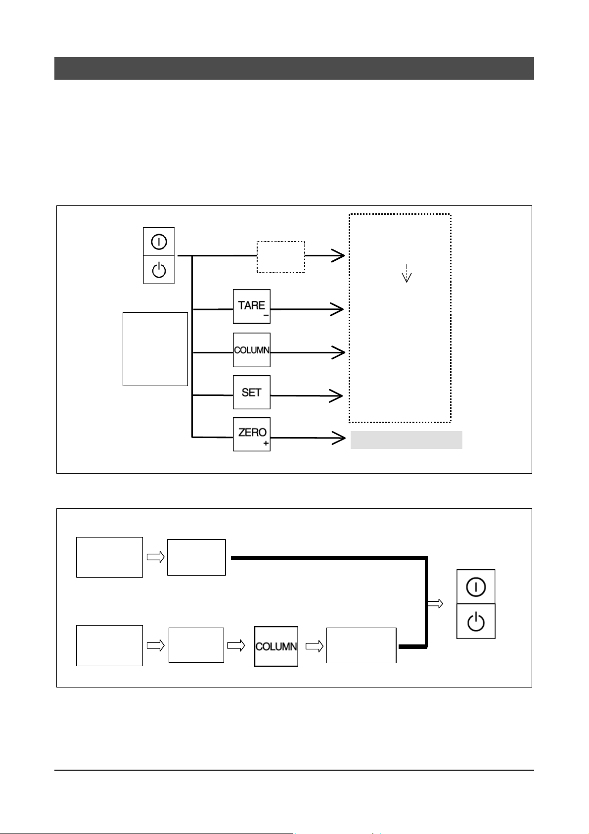
2.1.1 Starting Each Mode
Scale ON
Release
ON/OFF key,
Then press one
of these keys
while all
segments are
illuminated
Start
Check
Operation Manual
Normal Mode
Voltage Check
(IGB only)
Setup Mode
Program Mode
Test Mode
2.1.2 Ending Test Mode
C1 Mode
C2 Mode
C3 to C9
Mode
In Mode
In Mode
Press for 2 seconds or more
You cannot return to Cx mode.
C3 to C9
Mode
Scale OFF
Manual No. 085-3435-07 9/45 IGB/IGX Series (Overseas Specifications) Service Manual
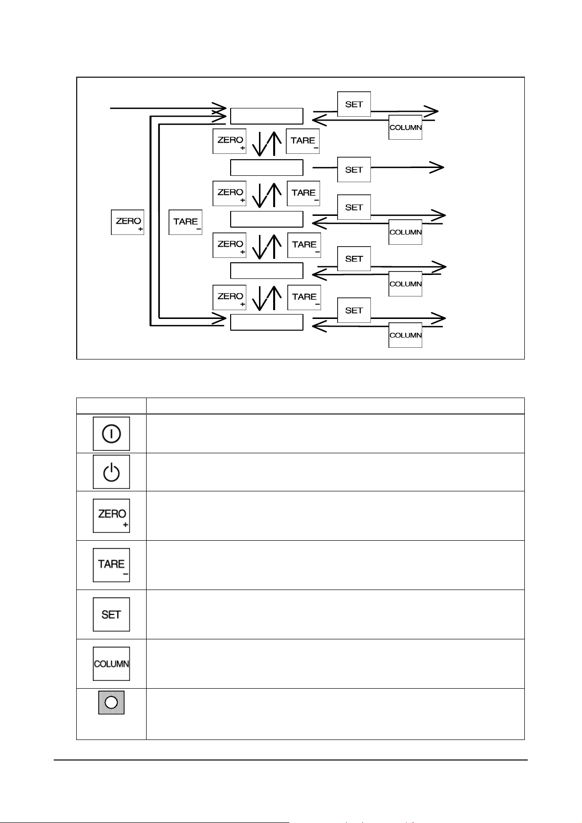
2.1.3 Test Mode Flow
2.1.4 Key Functions
C1
C2
C3 to C6
C8, C9
C7
To each C1
mode setup
Key check
mode
Each mode
operation
Scale function
Setup mode
Each mode
operation
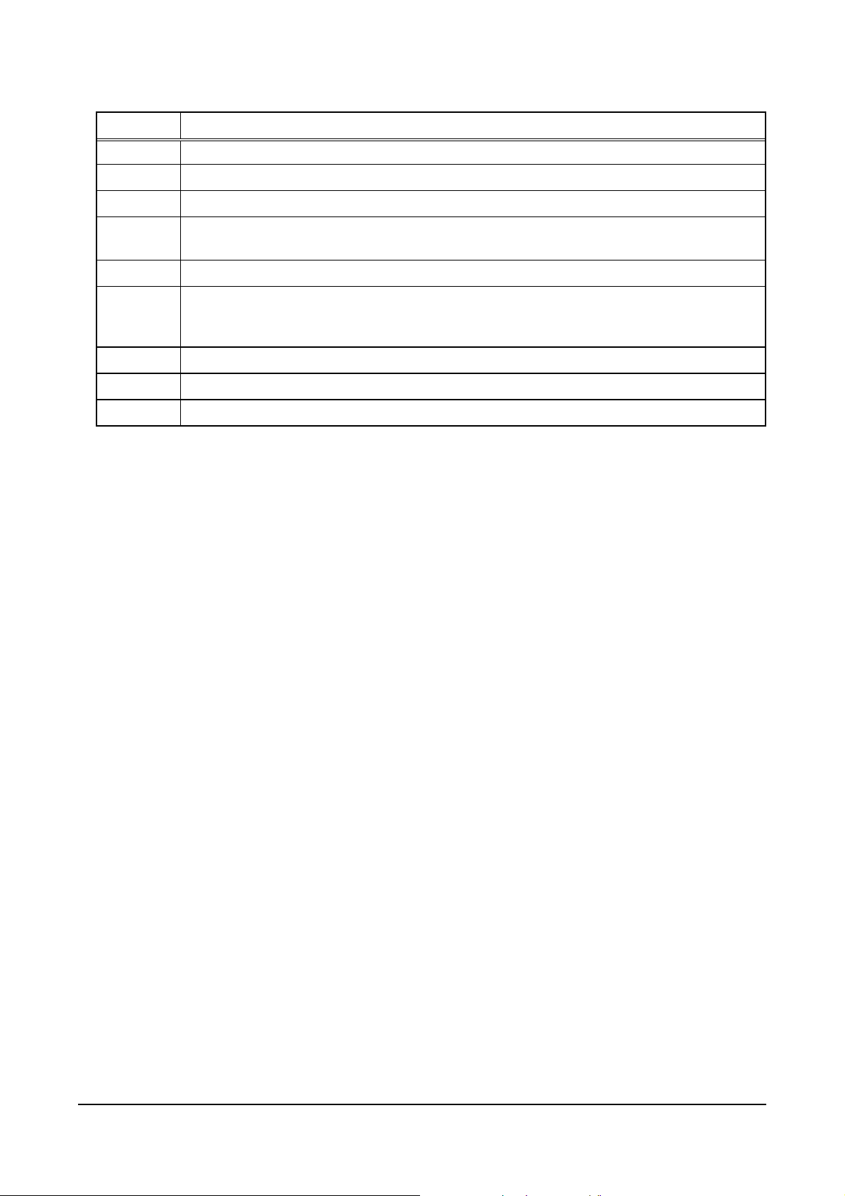
Key Function
Turns the power ON or OFF for the IGB Series.
Turns the power ON or OFF for the IGX Series.
+5V is always supplied to the circuit voltage.
Increases the numeric value (when the numeric value is set).
Advances the mode (when conditions are set).
Adjusts the zero point.
Decreases the numeric value (when the numeric value is set).
Reverses the mode (when conditions are set).
Adjusts the span point.
Determines the data in the Details Mode.
Changes between “+ Adjust” (ZERO ³ key [u display]) and “- Adjust” (TARE key
[d display]) when the span is adjusted.
Returns to each mode.
(Tact switch on the main board)
Saves the E2ROM data of each item setting of C1 mode.
Memory
switch
Manual No. 085-3435-07 10/45 IGB/IGX Series (Overseas Specifications) Service Man ual
2.1.5 Mode List
Mode Contents
*C1 Country No., Scale No., Zero point, Span adjustment
C2 Key check
C3 Display check 1 (simplified check), All LEDs light up
C4
C5 Program No. display
*C6
*C7 Settings for weighing conditions
C8 Reading E2ROM data
C9 Board check (A/D check, Interface check) for factory inspection
Display check 2 (detailed check), Each segment lights in sequence for each display
digit.
RAM clear (Program mode data)
E2ROM clear (Program mode data and Test mode C1 data)
(Span adjustment is required)
Manual No. 085-3435-07 11/45 IGB/IGX Series (Overseas Specifications) Service Man ual
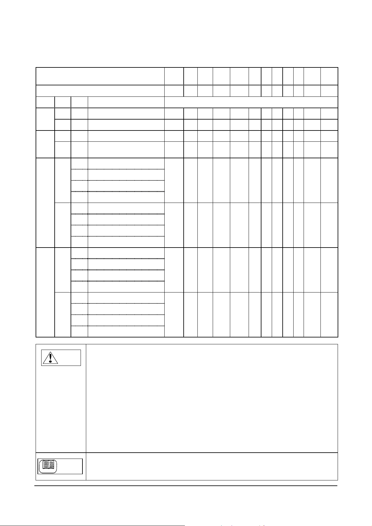
2.2 C1 Mode (Country No., Scale No., Zero point, Span adjustment)
e
2.2.1 Country No. Table
Country Name USA 1 EU AUS ASIA USA 2 JPN
Country Code 0 1 2 3 4 5 6 7 8 9 10 99
ADRS POS WGT Function Default Data (Change not allowed)
112 A H Start width 2 2 2 2 2 2 2 2 2 2 4 -
B H Stable/Re-stable count 3 3 3 3 3 3 3 3 3 3 3 -
113 A H Stable/Re-stable width 4 4 4 4 4 4 4 4 4 4 4 -
B H
114 A 1 Zero point mark
2 Over-scale display
4 Display less than true zero
8 Decimal point display
B 1 Over-scale range
2 Tare subtraction
4 Tare clear with ZERO key
8 Zero suppress
115 A 1 Key-in tare subtraction
Re-stable operation start width
4 4 4 4 4 4 4 4 4 4 4 -
2 8 0 8 2 8 0 8 4 0 5 -
0 6 6 0 0 6 6 0 0 6 0 -
IDV
SET
2 Zero tracking
4 Micro weight follow-up
8 Unstable width
B 1 PLU display (IGB only)
2 Stable display (IWB only)
4 Reserved
8 Reserved
1. By setting the country code, weighing conditions will function based on the default data from
Note
address 112 to 115.
2. The data is set to meet certified conditions for each country, so there is no need to change the
data.
3. Position “A” indicates the upper position of one-byte data, and “B” indicates the lower position.
4. As for Weight, a function is selected with “1”, “2”, “4”, and “8” in bit unit, and “H” indicates
Hexadecimal data.
5. Individual setting value “99” cannot be entered. (Displayed only when settings are changed in C7
mode)
6. “USA 2” code is settings to allow changing between “lb” and “kg” at anytime even in cases other
than a stable condition at zero point. (“USA 1” can change between “lb” and “kg” only when the
condition is stabilized at zero point)
When using this function, a maximum of 0.2e error may occur in weighing immediately after the
change. This error is calibrated by zero point adjustment (or zero tracking), and an accurate
weighing is guaranteed.
When selecting the weighing capacity exclusively for either “lb” or “kg”, use “USA 1”.
0 0 0 0 0 0 0 0 0 0 4
0 6 6 6 4 6 6 6 5 5 5
-
-
Refer to “Weighing Condition Data Table” for detailed function selection.
Refe re nc
Reference
Manual No. 085-3435-07 12/45 IGB/IGX Series (Overseas Specifications) Service Man ual
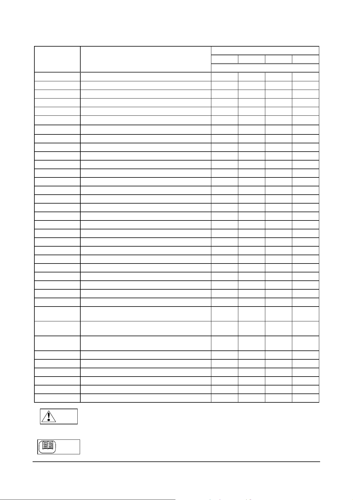
2.2.2 Scale No. Table
e
Scale No. Specifications
0 150kg (0.05kg/0.02kg) Multi Interval 6 C 3 8
1 60kg (0.02kg/0. 01kg) Multi Interval 2 B 3 8
2 30kg (0.01kg/0.005kg) Multi Interval B B 3 8
3 15kg (0.005kg/0.002kg) Multi Interval 7 C 3 8
4 6kg (0.002kg/0.001kg) Multi Interval 3 B 3 8
5 6000g (2g/1g) Multi Interval 0 B
6 3000g (1g/0.5g ) Multi Interval 9 B
7 120kg (0.02kg) 1/6000 Single Range 6 B 2 8
8 60kg (0.01kg) 1/6000 Single Range 2 B 2 8
9 30kg (0.005k g) 1/6000 Single Range B B 2 8
10 15kg (0.002kg) 1/7500 Single Range 7 B 2 8
11 6kg (0.001kg) 1/6000 Single Range 3 B 2 8
12 300kg (0.1kg) 1/3000 Single Range 1 B 2 8
13 150kg (0.05kg) 1/3000 Single Range A 8 2 8
14 60kg (0.02kg) 1/3000 Single Range 6 8 2 8
15 30kg (0.01kg) 1/3000 Single Range 2 8 2 8
16 15kg (0.005kg) 1/3000 Single Range B 8 2 8
17 6kg (0.002kg) 1/3000 Single Range 7 8 2 8
18 6000g (2g) 1/3000 Single Range 4 8 A 8
19 3000g (1g) 1/3000 Single Range 0 8 A 8
20 150kg/60kg (0.05kg/0.02kg) Dual Range 6 C 5 8
21 60kg/30kg (0.02kg/0.01kg) Dual Range 2 B 5 8
22 30kg/15kg (0.01kg/0.005kg) Dual R ange B B 5 8
23 15kg/6kg (0.005kg/0.002kg) Dual Range 7 C 5 8
24 6kg/3kg (0.002kg/0.001kg) Dual Range 3 B 5 8
25 6000g/3000 (2g/1g) Dual Range 0 B D 8
26 3000g/1500 (1g/0.5g) Dual Range 9 B D 8
27 150kg/150k (0.1kg/0.05k g Dual Range
Fishery specification
28 150kg (0.05kg) 1/3000 Single Range
Body weight specification
29 30kg (0.01kg) 1/3000 Single Range
Baby scale specification
30 300lb/150kg (1/3000) Multi Interval 6 C 7 8
31 150lb/60kg (1/ 3000) Multi Interval 2 B 7 8
32 60lb/30kg (1/3000) Multi Interval B B 7 8
33 30lb/15kg (1/3000) Multi Interval 7 C 7 8
34 15lb/6kg (1/3000) Multi Interval 3 B 7 8
99 Individual scale settings - - - -
1. By setting the Scale No., the scale will function acc ording to default data of addresses 110 and
111.
2 The above data determines each specificati on, so changing the data is prohibited.
3 Data A indicates the upper position of the on e-byte data, and B indicates the lower position.
Refer to “Weighing Condition Data Table” for data details.
Referenc
Note
Reference
Address
110A 110B 111A 111B
Default Data
B
B
8
8
A 8 5 8
A 8 4 2
2 8 4 2
Manual No. 085-3435-07 13/45 IGB/IGX Series (Overseas Specifications) Service Man ual
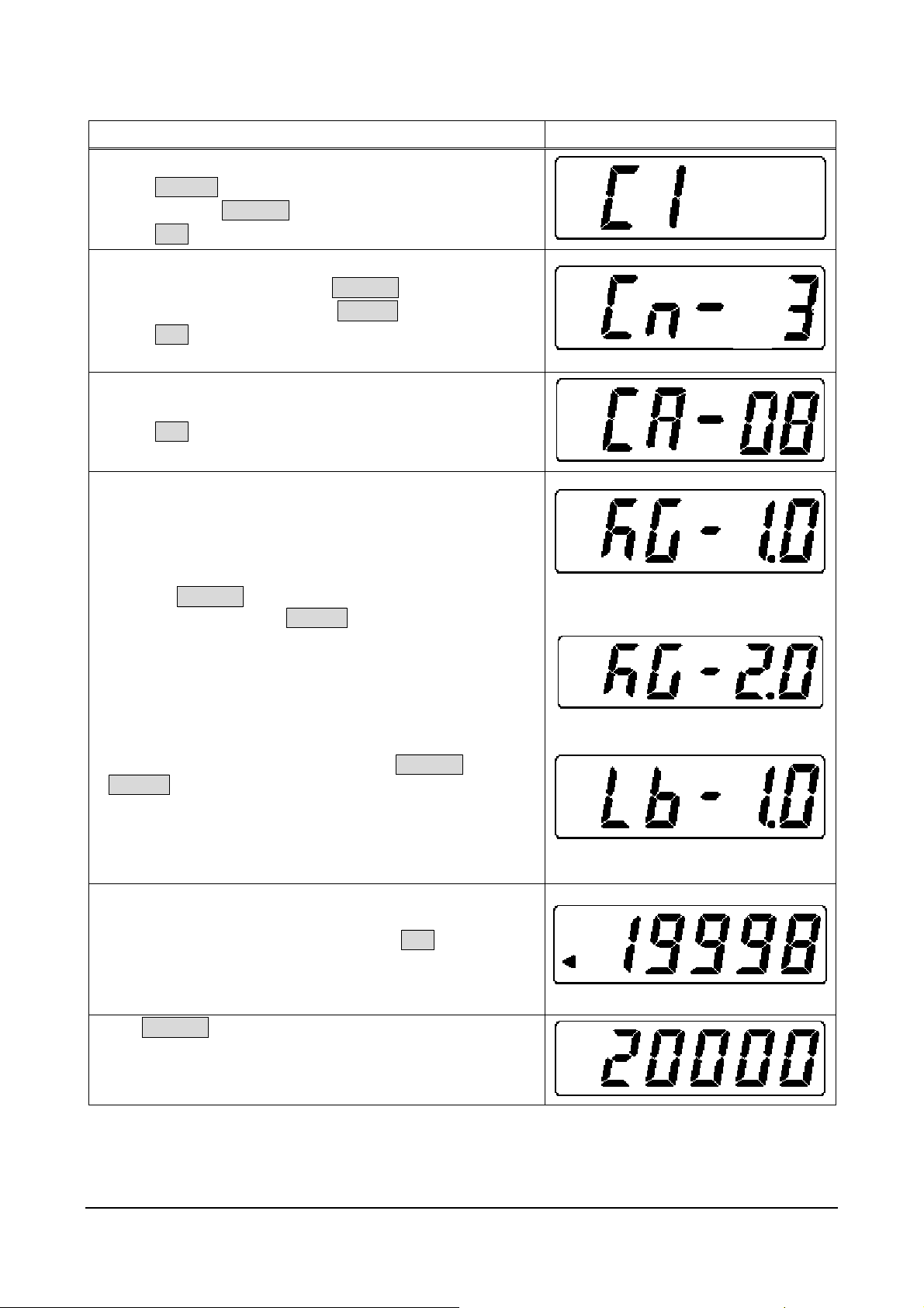
2.2.3 Operation Procedure
Operation Display
1. Starting Test Mode (C1)
Press ON/OFF.
Press and hold ZERO(+) while all segments are lit.
Press SET.
2. Setting Country Number
To increase the number, press ZERO(+).
To decrease the number, press TARE(-).
Press SET.
[Example] Asia = 3
3. Setting Scale Number
When setting “60kg”, select “08”.
Press SET.
4. Selecting Weight at Span Adjustment
The following weight can be selected:
kg: 1/1.0→1/2.0→1/2.5→1/5.0 of weighing capacity
lb: 1/1.0→1/2.0→1/2.5→1/5.0 of weighing capacity
・ Pressing ZERO(+) selects the next item in the above
sequence, and pressing TARE(-) selects the previous item.
kg unit: Same weight is used as weighing
capacity.
[Example] Selecting “kg” unit and “1/2.0” for weighing
capacity “150kg” will require the total 75kg
weight.
To change between “lb” and “kg”, press ZERO(+) and
TARE(-) at the same time.
5. Zero Point Adjustment
After selecting the weight amount, ensure that nothing is
placed on the weighing platter, then press SET.
The previously set zero point A/D data will be displayed.
Zero point indicator W will light up.
Press ZERO(+) to set “20000” counts forcibly.
Zero point indicator W will go off.
kg unit: Half weight is used of weighing
capacity.
lb unit: Same weight is used as weighing
capacity.
Manual No. 085-3435-07 14/45 IGB/IGX Series (Overseas Specifications) Service Man ual
 Loading...