


Installation Instructions | Installationsanleitung | Notice d’installation
Istruzioni per l’installazione | Instrucciones de instalación
Sartorius
YDO01M-232 (A11)
YDO01M-232CLK (A31)
YDO01M-232CO (A1)
YDO01M-485 (A2 | A3)
YDA01M-20MA (A9)
YDO01M-IO (A5)
YDO01M-EN (B9)
Data Output Port for Midrics® COM1 and UniCOM Interfaces
Datenausgang für Midrics®-Schnittstellen COM1 und UniCOM
Port de sortie pour interfaces Midrics® COM1 et UniCOM
Porta in uscita per interfacce Midrics® COM1 e UniCOM
Puerto de salida para interfaces COM1 y UniCOM de Midrics®
98647-004-16

2
English – page 3
In cases involving questions of interpretation, the German-language version shall prevail.
Deutsch – Seite 20
Im Auslegungsfall ist die deutsche Sprache maßgeblich.
Français – page 37
En cas de questions concernant l’interprétation, la version en langue allemande fera autorité.
Italiano – pagina 54
In caso di interpretazione dubbia, fa testo la versione in lingua tedesca.
Español – página 71
En caso de interpretación, la versión en lengua alemana será determinante.

3
Intended Use
The YD.01M-... data output port is
designed for installation in Midrics®
model MIS... and MW... display and
control units and complete scales as an
optional standard COM1 interface or
UniCOM universal data interface.
For COM1:
– YDO01M-232 (Option A11):
Bidirectional RS-232 data interface.
You can connect the following to the
YDO01M-232 port: Printer (YDP02IS,
YDP03, YDP04IS, YDP12IS, universal
printer) or computer (SBI, XBPI or SMA
operation).
– Alibi memory
– YBT01 external Bluetooth adapter
– YRD02Z second display
– USB adapter cable, for connecting
a computer over USB (part no.
YCC01IS).
– YDO01M-232CLK “Clock" (Option A31):
As standard RS-232, plus date/time
For UniCOM:
– YDO01M-232CO (Option A1):
as for RS-232, plus digital I/O (TTL/5V)
– YDO01M-485 (Options A2 and A3):
Bidirectional data interface, electrically
isolated, for use with the RS-422
(Option A2) or RS-485 (Option A3) protocol.
The YDO01M-485 lets you network up
to 32 Midrics scales/display and control
units in an XBPI-bus.
– YDA01M-20MA (Option A9):
Analog output port for use as a current
interface (0/4 to 20 mA, 0 - 24 mA) or
voltage interface (0 to 24 volts).
The YDA01-20MA module enables connection of a PLC system or a remote
analog display unit.
– YDO01M-IO (Option A5):
Digital input/output module; for connecting Midrics equipment to external
controllers.
– YDO01M-EN (Option B9):
Ethernet interface (e.g. for connecting
to a PLC or PC).
Symbols
The following symbols are used in
these instructions:
§ indicates required steps
$ indicates steps required only under
certain conditions
> describes what happens after you
have performed a particular step
! indicates a hazard
Contents
3 Intended Use
4 Installation in the Display and
Control Unit
4 Installing the COM1 PCB
5 Installing the UniCOM PCB
7 Installing the Interface Cable
8 Configuring the Interface Module:
YDO01M-485, YDA01M-20MA
10 YDO01M-IO: Specifications
10 YDO01M-EN
11 Pin Assignment Charts
11 COM1
11 UniCOM
12 Configuring COM1 and UniCOM
16 Synchronization
17 Data Interfaces
17 Data Input Format (Commands)
18 Data Output Format
19 GMP-compliant Printouts

4
Installation in the Display and Control Unit
Installation
Installation of the interface module in the Midrics display and control unit (and additionally the installation of the cable gland and connection of the connecting cable to the terminal screw strip) is only required if the Midrics display and control unit was not
equipped at the factory with this data output in accordance with the customer's order.
Notes:
§ The interface module should be installed by a certified technician who has received
specialized training from Sartorius.
§ IP65 protection:
Make sure to use the connecting cable with screw-lock hardware designed for the interface module in question (see “Accessories").
!Make sure to disconnect the equipment from power before beginning installation.
!Any installation work that does not conform to the instructions in this manual will result
in forfeiture of all claims under the manufacturer's warranty.
!Installation work that affects the IP65 protection rating must be performed with extreme
care.
The cable gland (IP65 protection) for connection of the interface to the display and control unit is covered by a protective cap. Please use extreme caution when performing any
work on the equipment that affects this cable gland.
§ To open the display and control unit, remove the screws from the front panel.
Installing the COM1 PCB:
§ Remove fastening screw.

5
§ Attach spacing bolts.
§ Plug in PCB mounting.
§ Plug the interface module (YDO01M-232 or YDO01M-232CLK) onto the digital PCB
in the Midrics display and control unit. To do this, attach the female terminal strips on
the interface module to the corresponding male terminal strips on the digital PCB.
§ Fasten the interface module with the screw.
The interface modules are equipped with their own terminal screw strips.
Connect the cable to this terminal strip.
Installing the UniCOM PCB:
§ Remove the 2 fastening screws.

6
§ Attach the 2 spacing bolts.
§ Plug in PCB mounting.
§ Plug the interface module (YDO01M-232CO, YDO01M-485, YDA01M-20MA or
YDO01M-IO) onto the digital PCB in the Midrics display and control unit. To do this,
attach the female terminal strips on the interface module to the corresponding male
terminal strips on the digital PCB.
§ Fasten the interface module with the 2 screws.
The interface modules are equipped with their own terminal screw strips.
Connect the cable to this terminal strip.

7
Installing the Interface Cable
§ Pin assignments: please see “Pin Assignment Charts" in this manual.
§ Use the cable gland to connect the peripheral device to the indicator.
§ Prepare the cable as follows:
– Expose approximately 10 cm (4 in) of the cable end for installation
– Remove all but approximately 1 cm (1/2 inch) of the shielding and fold it back over the
casing
– Strip the casing from approximately 1 mm (1/2 inch) of the wires and attach ferrules to
the wire ends.
§ Attach the cable gland:
!Please use extreme caution when performing any work on the equipment that affects this
cable gland. Use a torque wrench and tighten the cable gland to 5 Nm.
– Remove the protective cap from the bore hole on the display and control unit.
– Guide the enclosed cable gland through the bore hole and secure it inside the housing
with the nut (1).
– Slide the cable gland over the cable until the clamps (3) are in contact with the shield (2).
Tighten the nut (4) until the sealing clamp (5) forms a slight ridge between nut and
cable.
– Make sure the shield is in contact with the clamps.
§ Connect the cable:
– Connect the wires securely in accordance with the terminal assignments.
– Please see “Pin Assignment Charts" in this manual for details.
§ Close the display and control unit. Make sure that the rubber seal between the front
panel and the housing is correctly positioned.
§ After you close the housing again, use a pressure gauge to check the integrity of the IP65
protection. For details, contact the Sartorius Service Center.
Setting the Operating Parameters in the COM1 and UniCOM Interfaces
After installing and configuring the interface module in the display and control unit,
select the parameters in the operating menu that correspond to your requirements.
For details, see “Configuring COM1 and UniCOM." For more information, refer to the
installation and operating instructions for the Midrics scale.
4
1
5
2
3

8
Configuring the Interface Module: YDO01M-485, YDA01M-20MA
YDO01M-485 (Options A2 and A3)
Characteristics
The YDO01M-485 module (serial RS-485/RS-422 interface, electrically isolated
1
) can be
operated with your choice of RS-485 or RS-422 protocol.
The module is configured by eight switches.
In addition to defining whether RS-485 or RS-422 is used, certain terminating resistors
(120 O) and/or bias resistors may have to be activated or deactivated, depending on
whether a network or point-to-point connection is used.
The positions of the switches are indicated in the drawing on the left. Close switches 1
through 4 for RS-422 operation.
The following list shows the functions of switches in the closed (“ON") position:
Function (on = closed) Switch
Terminating resistor, transmitting side 120O 1 - 1
Bias resistor, transmitting side (TxD+, pull-up) 680O 1 - 2
Bias resistor, transmitting side (TxD–, pull-down) 680O 1 - 3
ON: RS-422 operation | open: RS-485 mode 1 - 4
Terminating resistor, receiving side 120O 2 - 1
Bias resistor, receiving side (RxD+, pull-up) 680O 2 - 2
Bias resistor, receiving side (RxD–, pull-down) 680O 2 - 3
No function 2 - 4
Note on setting the switches:
Switches must be set pairwise as follows:
– Switches 1–2 and 1–3: both ON or both OFF
– Switches 2–2 and 2–3: both ON or both OFF
Operation as an RS-485 Interface (Option A3):
§ Switches 1 - 4 must be open to operate the module in RS-485 mode (factory setting).
§ If necessary, deactivate the bias resistors for the RS-485 mode. To do this, open the
switch (factory setting).
The bias resistors must occur no more than once per data transmission path (whether
over a network or in a point-to-point connection); otherwise, transmission errors may
occur. Please refer to the specifications or wiring diagram for the remote station or
network node in question for detailed information. Always activate or deactivate bias
resistors in pairs.
§ The terminating resistor (transmitting side, switch 1 – 1) must be activated if the device
is at either end of an RS-1 bus system, or when connected point-to-point with another
device. The remote station must also have a 120-O terminating resistor. If necessary,
activate the terminating resistor (120 O) for RS-485 operation:
close switches 1 - 1 and 2 - 1 (“ON")
Operation as an RS-422 Interface (Option A2):
§ Close switches 1 - 4 for RS-422 operation (“ON")
§ If necessary, deactivate the bias resistors for RS-422-operation. To do this, open the
switches.
§ Activate the terminating resistor on the receiving side (switch 2 – 1), if no external termi-
nating resistor is available. Always deactivate terminating resistors on the transmitting
side (switch 1 – 1).
1
) The shielding in the connecting cable is connected at one end to the housing of the indicator.
The indicator is connected to the protective grounding conductor.

9
YDA01M-20MA (Option A9)
Characteristics
The YDA01M-20MA interface module is an analog output port. This module can be
operated as either a current interface (0/4 - 20 mA, 0 - 20 mA) or a voltage interface
(0 to 10V. The internal power supply is electrically isolated
1)
).
The interface module can be configured for any of the following 4 operating states:
– Voltage interface, 0 to 10 V
– Current interface, 0 to 20 mA
– Current interface, 4 to 20 mA
– Current interface, 0 to 24 mA
Configuring the module for the intended use involves opening and closing certain
switches. The positions of the switches are indicated in the drawing on the left.
The operating state is defined by the configuration of switches 1 and 2 (switches 3 and 4
have no function):
Operating status Switch
Voltage interface, 0 to 10 V SW 1–1: closed = “ON",
SW 1–2: open
Current interface, 0 to 20 mA SW 1–1: open,
software 1–2: closed = “ON"
Current interface, 4 to 20 mA SW 1–1: open, software 1–2: open
(factory setting)
Current interface, 0 to 24 mA SW 1–1: closed = “ON"
SW 1–2: closed = “ON"
1
) The shielding in the connecting cable is connected at one end to the housing of the display and control unit.
The display and control unit is connected to the protective grounding conductor.
– Max. load: 390 ohms
Notes
– The shielding in the current interface connecting cable is connected at one end to the
housing of the display and control unit.
– The display and control unit is connected to the protective grounding conductor.
– If the display and control unit is operated with a rechargeable battery, operation of the
current interface is not possible.
§ The YDA01M-20MA is installed directly on the digital PCB in the Midrics display and
control unit. For details, please see “Installation in the Display and Control Unit."

10
Example: Basic Circuit Diagram
YDO01M-IO, Option A5:
Specifications
Digital inputs
– Quantity: 5
– Low level: –3 V to +5 V
– High level: +11 V to +30 V
– Maximum current
consumption: 2.6 mA at 15 V
– Inputs are activated by applying
the corresponding voltage.
Digital outputs
– Quantity: 5
– Maximum current flow per channel:
100 mA
– Voltage range: 0–30 VDC
– Each output is formed
by an opto-electronic coupler.
YDO01M-EN (Option B9)
Equipment Supplied
– YDO01M-EN interface module
– Operating instructions (this document)
– Interface description (fieldbus for
TCP Modbus)
Assembly
Connect interface module YDO01M-EN
(Ethernet interface) directly to the digi-
tal board of the scales without configu-
ration. For more information, please
refer to chapter entitled “Installing Data
Output Ports in the Indicator”.
Insert the YCC02RJ45M7 plug on the
Sartorius Ethernet cable (option M38)
into the port of the interface module.
Note:
!Only use cables and plugs that conform
to the Ethernet specification (CAT5 or
better):
Ethernet cable with Sartorius order no.
YCC02RJ45M7 (Option M38) cable
gland
Use the interface module only with the
following devices:
– Indicator MIS1, MIS2 (IP65)
– Complete scales MW1, MW2 (IP65)
1
23
4
1
0.2A
4
30V
OUTx_high
OUTx_low
Inputx_high
LV1
LV1
LV2
23
Inputx_low
LV2

11
Pin Assignment Charts
COM1
– RS-232 interface: YDO01M-232
(Option A11), YDO01M-232CLK (A31):
Pin assignments in the 8-contact terminal screw strip on the interface module:
Pin 1: +12 V: Supply voltage for
Sartorius printers
Pin 2: Reset_Out
(peripheral device restart)
Pin 3: +5 V Out
Pin 4: Ground (GND)
Pin 5: Clear to send (CTS)
Pin 6: Data terminal ready (DTR)
Pin 7: Data input (R+D)
Pin 8: Data output (T+D)
UniCOM
– Pin assignments in the two 10-contact
terminal screw strips on the interface
module:
RS-232 interface: YDO01M-232CO
(Option A1):
Pin 1: Clear to send (CTS)
Pin 2: Data terminal ready (DTR)
Pin 3: Data input (R+D)
Pin 4: Data output (T+D)
Pin 5: Ground (GND)
Pin 6: Universal IN
Pin 7: Control output: “lighter"
Pin 8: Control output: “equal"
Pin 9: Control output: “heavier"
Pin 10: Control output: “set"
Pin 11: +12 V: Supply voltage for
Sartorius printers
Pin 12: Reset_Out
(peripheral device restart)
Pin 13: Ground (GND)
Pin 14: Ground (GND)
Pin 15: +5 V output
Pin 16: +5 V switched
(e.g., for bar code scanner)
Pin 17: Ground (GND)
Pin 18: Ground (GND)
Pin 19: Not connected
Pin 20: Ext. supply voltage output
+15V to 25V
Digital I/O interface:
YDO01M-IO (Option A5):
Pin 1: External output port 5: low
Pin 2: External output port 5: high
Pin 3: External output port 4: low
Pin 4: External output port 4: high
Pin 5: External output port 3: low
Pin 6: External output port 3: high
Pin 7: External output port 2: low
Pin 8: External output port 2: high
Pin 9: External output port 1: low
Pin 10: External output port 1: high
Pin 11: Input port 5: low
Pin 12: Input port 5: high
Pin 13: Input port 4: low
Pin 14: Input port 4: high
Pin 15: Input port 3: low
Pin 16: Input port 3: high
Pin 17: Input port 2: low
Pin 18: Input port 2: high
Pin 19: Input port 1: low
Pin 20: Input port 1: high
– Pin assignments in the two terminal
screw strips on the interface module:
YDO01M-485: RS-485 mode
(Option A2):
Pin 1: Data + (T+D-R+D+)
Pin 2: Data - (T+D-R+D-)
Pin 3: Not connected
Pin 4: Not connected
Pin 5: Signal ground, electrically
isolated (GND_GALV)
Pin 6: Signal ground, electrically
isolated (GND_GALV)
Pin 11: Ext. supply voltage input
+15V to 25V *
Pin 12: Ext. supply voltage input
+15V to 25V *
Pin 13: Ground (GND) *
Pin 14: Ground (GND) *
1
2
3
4
5
66
YDO01M-485: RS-422 mode
(Option A3):
Pin 1: Data output + (T+D+)
Pin 2: Data output - (T+D-)
Pin 3: Data input + (R+D+)
Pin 4: Data input - (R+D-)
Pin 5: Signal ground, electrically
isolated (GND_GALV)
Pin 6: Signal ground, electrically
isolated (GND_GALV)
Pin 11: Ext. supply voltage input
+15V to 25V *
Pin 12: Ext. supply voltage input
+15V to 25V *
Pin 13: Ground (GND) *
Pin 14: Ground (GND) *
* = Not electrically isolated
YDA01M-20MA
(current/voltage interface):
6-pin terminal screw strip on the interface module
Pin 1: I_out (+)
for current interface
(0/4 to 20/24 mA)
Pin 2: I_in (–)
for current interface
(0/4 to 20/24 mA)
Pin 3: V_out (+)
for voltage interface,
0V to + 10V
Pin 4: V_in (–)
for voltage interface,
0V to + 10V
Pin 5: GND, electrically isolated
(electrically isolated ground)
Pin 6: GND, electrically isolated
(electrically isolated ground)
Pin assignment of the
Ethernet interface (RJ45)
YDO01M-EN (Option B9):
Pin 1: TxD+
Pin 2: TxDPin 3: RxD+
Pin 4: Not in use
Pin 5: Not in use
Pin 6: RxDPin 7: Not in use
Pin 8: Not in use
Chassis: GND
1
2
3
4
5
66
1
2
3
4
5
66

12
Configuring COM1 and UniCOM
Operating menu overview for the COM1 and UniCOM interfaces
(see also “Operating Menu Overview" in the chapter entitled “Configuration" in the Midrics operating instructions).
Appl
Fn-Key
Setup WP-1
COM1 OFF *
DATPROT SBI *
(data record) XBPI-232
SMA
Printer YDP01IS Line *
Label
Label, man. form feed
YDP02
YDP03
YDP02IS Line *
Label
UNI-PRI (universal printer)
YDP04IS Line *
Label
Label, man. form feed
MEMORY YAM01IS (Alibi memory)
UniCOM OFF *
DATPROT SBI *
(data record) XBPI-232
XBPI-485
SMA
ETHERNET Source IP: 192.168.0.1 *
Source name
Listen port: 49155 *
Subnet mask: 255.255.255.0 *
Gateway IP: 0.0.0.0 *
DNS IP: 0.0.0.0 *
Target IP: 0.0.0.0 *
Target port: 49155 *
Protocol TCP *
UDP
Mode SBI (server)-SRV* 6.1. Data output manual/automatic
6.1.1 Manual without stability
6.1.2 * Manual after stability
6.1.4 Automatic without stability
6.1.5 Automatic with stability
6.1.7 Print log for PC
7.2. Output: line format
7.2.1 For raw data: 16 characters
7.2.2 * For other apps: 22 characters
SBI-C/S 6.1. Data output manual/automatic
(client) 6.1.1 Manual without stability
6.1.2 * Manual after stability
6.1.4 Automatic without stability
6.1.5 Automatic with stability
6.1.7 Print log for PC
6.3. Time-dependent autom. output
6.3.1 * 1 display cycle
6.3.2 2 display cycles
6.3.4 10 display cycles
6.3.7 100 display cycles
7.2. Output: line format
7.2.1 For raw data: 16 characters
7.2.2 * For other apps: 22 characters
xBPI
SMA
Modbus/TCP

13
Setup UniCOM Printer YDP01IS Line *
Label
Label, man. form feed
YDP02
YDP03
YDP02IS Line *
Label
UNI-PRI (universal printer)
YDP04IS Line *
Label
Label, man. form feed
MEMORY YAM01IS (Alibi memory)
ANALOG (analog interface)
CTRL IO: CTR INP: 8. 4. x TTL; for YDO01M-232CO, Option A1
Control Control inputs 8. 17. x Electrically isolated; for
inputs/ to YDO01M-IO, Option A5
outputs 8 . 21. x
CTR OUT: 8. 24. x Electrically isolated; for
Control to YDO01M-IO, Option A5
outputs 8. 28. x
* = Factory setting

14
Ethernet interface
In the “UNICOM” menu, select
“ETHERNET” to enter numerical
values under Source IP, ListenPort, etc.
Under Source name, both letters and
numbers can be used. A maximum of
15 characters can be entered. Enter
either a source name or a source IP
address (not both).
Port numbers
Validity range: 0 – 65535
Since many of the ports up to 49150
have already been allocated, we recommend using port numbers above 49150.
This does not apply to Modbus/TCP,
because the following port number
applies here: 502 (see the fieldbus
brochure for details)
Configuring the Interface
You can configure the UniCOM universal data interface for the required operating state (connection of a peripheral
device).
The diagram on the preceding page
shows the relevant section of the
operating menu.
For additional information, see the
chapter entitled “Settings" in the
Midrics operating instructions.
RS-485/RS-422 Interface
If the PCB is configured for use in the
RS-422 operating mode, you can select
the SBI, XBPI-232, or SMA menu item.
YDA01M-20MA Analog Interface
You can configure the following
parameters in the operating menu:
– Output value (menu line 8.12):
8.12.1: Net value
(factory setting)
8.12.2: Gross value
– Error display (menu line 8.13):
8.13.1: High level (20 mA)
(factory setting)
8.13.2: Low level (0/4 mA):
5V on this interface during
operation.
– Output mode (menu line 8.14):
8.14.1: Zero to maximum capacity
(factory setting)
8.14.2: Minimum/maximum values
– Output of minimum/maximum values
(menu line 8.15):
8.15.1: Min. (0/4 mA) input in kg
8.15.2: Max. (20 mA) input in kg
By selecting min./max. values you can
specify the weighing range for output
on the 0/4 to 20mA (0 to 10 V) interface. This selection applies as well to an
SBI scale, but only for the net value.
Input of min. and max. values is always
in kilograms. You can enter negative
values if desired. You can also enter a
min. value that is higher than the max.
value, to effect falling current output.
Examples:
Rising current curve
Min. value, net: -1 kg
Max. value, net: 4 kg
Falling current curve for XBPI scales
Min. value: 5 kg
Max. value: 1 kg
Falling current curve for SBI scales
Min. value: 5 kg
Max. value: 1 kg

15
Ethernet interface: Initialization
Display: Initialization completed
Once initialization of the Ethernet
module has been completed successfully,
the “ ” symbol is displayed.
Network module
initialized
If initialization was not successful,
no symbol is displayed. The symbol
provides no information about the
connection status in relation to the
network.
TCP connections:
In the SBI-C/S operating mode, Midrics
always terminates the connection
independently, after 1 second.
In the other operating modes
(SBI-SRV, SMA, XBPI, ModBus/TCP) the
connection is maintained until it is disconnected by the PC (client). It is only
possible to establish one connection at
a time.
Ethernet interface: Features
Source IP: IP address of the Midrics indicator
If the address 0.0.0.0 is selected, you need to enter a name under
“Source name.” In this case, the IP address should be dynamically allocated
by a DHCP server located within the network.
Source name: This parameter is alternative to the “Source IP” input. A name that is up
to 15 characters in length and serves to identify the Midrics can be entered.
In this case, the address 0.0.0.0 must be selected as the source IP. The name
is announced to the domain name service (DNS) if
– an IP address has been entered under DNS IP
or
– an IP address has been allocated over DHCP.
Device port: Number of the port on which the Midrics listens for server operation.
Subnet mask: IP address mask for the activation of IP addresses in a subnet. If the mask
is to be allocated using a DHCP server, 0.0.0.0 must be entered.
Gateway IP: IP address of a gateway
Address of desired server located in another network using target IP. If the IP
address is to be allocated dynamically using a DHCP server, 0.0.0.0 must be
entered.
Target IP: Address of the server that is to receive the Midrics data.
Important for operation of the Midrics as a client if the SBI mode has been
selected in combination with automatic data output. When using UDP,
an IP address must also be entered here.
Target port: Port number on which a server with the target IP listens in order to receive
data from the Midrics.
Protocol: Select the transport protocol to be used to transmit data over Ethernet.
Please select either:
– TCP, connection-oriented with high data security
or
– UDP, connectionless (does not effect Modbus/TCP)
Mode: Select the data format that contains the user data embedded in TCP or UDP
(e.g. SMA is tunnelled over Ethernet using TCP or UDP).
With the SBI-SRV, XBPI and SMA protocols, the Midrics is always to be seen
as a server. Under SBI-C/S, the Midrics is simultaneously a server and a client.
Client mode is activated when the p [Print] button is pressed or the data
output parameter has been set to “automatic”. For the OPC mode, set the
menu code for “SBI server.” In all other instances, the Midrics is a server.
Under ModBus/TCP, the Midrics is always active as a server (also see the field
bus brochure).
Power-on
response: If the interface module is active, the display of the weight value may be
delayed by up to 20 seconds.

16
Synchronization
Data communication between the display and control unit and a computer
takes the form of messages
(“telegrams") made up of ASCII code.
For error-free data communication, the
settings for baud rate, parity, handshake mode and character format must
be the same at both ends.
You can configure the interface settings
in the Setup menu so that they match
those of the computer. You can also
define parameters in the indicator to
make data output dependent on various
conditions. The conditions that can be
configured are listed in the descriptions
of the application programs (see operating instructions for the Midrics scale).
If you do not connect a peripheral
device to the display and control unit's
interface port, this will not generate an
error message.
Handshake
The weighing instrument interface (Sartorius Balance Interface = SBI) has
transmit and receive buffers. You can
define the handshake parameter in the
display and control unit's Setup menu:
– Hardware handshake (CTS/DTR)
– Software handshake (XON, XOFF)
Hardware Handshake
Hardware handshake with a 4-wire
interface: 1 more character can be
transmitted after CTS (clear-to-send).
Software Handshake
The software handshake is controlled
via XON and XOFF. When a device is
switched on, XON must be transmitted
to enable a connected device to communicate.
The data transmission sequence is as
follows:
Scale ––– byte –––> Computer
(trans- ––– byte –––> (receiving
mitting device)
device)
––– byte –––>
––– byte –––>
<–– XOFF –––
––– byte –––>
––– byte –––>
...
(Pause)
...
<–– XON –––
––– byte –––>
––– byte –––>
––– byte –––>
––– byte –––>
Transmitting Device
Once XOFF has been received, it prevents further transmission of characters.
When XON is received, it re-enables the
transmitting device to send data.
Receiving Device
To prevent too many control commands
from being received at one time, XON is
not transmitted until the buffer is
almost empty.

17
Data Interfaces
Configuring the Data
Interface as a COM Port
(datprot)
Configure the interface as a COM port
in the Setup menu under COM1 or
UniCOM, under the “Data Protocol"
(datprot) menu item.
SBI Communication
This is a simple ASCII interface.
Data output is configured under menu
lines 6.1 and 6.3:
– Manual output of displayed value with
or without stability (menu items 6.1.1
and 6.1.2)
– Automatic output of displayed value
with or without stability (menu items
6.1.4 and 6.1.5) at intervals defined by
display updates. The number of display
updates comprising an output interval
is configured under menu item 6.3.
– Output of a configurable printout.
Output is linked to the Printout
(prtprot) settings.
If you do not activate and configure a
user-definable data record, the printout
simply contains the current value displayed on the indicator (weight with
unit, calculated value, alphanumeric
display).
SMA Communication
Standardized communications protocol
of the Scale Manufacturers Association
Data Input Format
(Commands)
You can connect a computer to your
display and control unit to send commands controlling weighing instrument
functions and applications via the interface port.
All commands use the same format
(data input format) starting with the
ESC character (ASCII 27) and ending
with a carriage return (CR; ASCII 13)
and a line feed (LF; ASCII 10). The total
length of a command is anywhere from
4 characters (1 command character
between the start and end described
above) to 7 characters (4 command
characters).
The table below shows the available
command characters; each command
must be flanked by the start and end
characters as described above.
Example: The command character for
output is “P" (“transmit readout
value"). The string “ESC P CR LF"
triggers this command.
Command Meaning
K Weighing mode 1
L Weighing mode 2
M Weighing mode 3
N Weighing mode 4
O Block keys
P Output readout
to data interface
R Unblock keys
T Tare and zero
(combination tare function)
f3_ Zero (see also the
“kZE_" command)
f4_ Tare (without zeroing;
as the “kT_" command)
kF1_ F1: Trigger k key function
kF2_ F2: Trigger c key function
(Midrics 2 only)
kF3_ F3: Trigger r key function
(Midrics 2 only)
kF4_ F4: Trigger O key function
(Midrics 2 only)
kF5_ F5: Trigger w key function
(Midrics 2 only)
Command Meaning
kF6_ F6: Trigger I key function
(Midrics 2 only)
KF7_ d key
kCF_ CF: Trigger c key function
(Midrics 2 only)
kP_ Trigger p key function
Output to printer port
kT_ Trigger T key function
(tare)
kZE_ Trigger ( key function
(zero)
x1_ Output model designation
of active weighing instrument.
Example: “LP6200S-0C"
x2_ Output serial number
of active weighing instrument;
Example: “0012345678"
x3_ Output software version
of active weighing instrument;
Example: “00-20-04"
z1_ Activate input for printout
header 1
z2_ Activate input for printout
header 2
txx...x_ xx...x: Enter letters
Length acc. to input
(Midrics 2 only)
The ASCII code for the “underline"
character is 95.
Format for entering printout header
lines: “ESC z x a ... a _ CR LF" where
x=(header line) 1 or 2, and a ... a: = up
to 20 characters of text, followed by the
“underline" character, carriage return
and line feed.

18
Error Codes:
Pos. 12345678910111213141516
***Err**##****CRLF
or ***Err*###****CR LF
*: Space
#: Error code number (2 or 3 digits)
Example (output of value: +1255.7 g):
Pos. 12345678910111213141516
+** * 1255. 7* g* * CRLF
Position 1: Plus or minus sign or space
Position 2: Space
Positions 3-10: Weight value with decimal point; leading
zeros are output as spaces.
Position 11: Space
Positions 12 - 14: Unit symbol or space
Position 15: Carriage return
Position 16: Line feed
Data Output Format with 22 Characters
(with Data Header)
Normal Operation:
Pos. 12345678910111213141516171819202122
IIIIII+*DDDDDDDD* UUUCRLF
or IIIIII-*DDDDDDDD* UUUCRLF
or ********************CRLF
I: ID code character, right-justified with spaces Space
+-: Plus or minus sign
*: Space
A: Digit or letter (max. 7 characters plus decimal point)
U: Unit symbol (1 to 3 letters, followed by 0 to 2 spaces)
CR: Carriage return
LF: Line feed
Special Codes:
Pos. 12345678910111213141516171819202122
Stat********––******CRLF
or Stat********H*******CRLF
or Stat********HH******CRLF
or Stat********L*******CRLF
or Stat********LL******CRLF
or Stat********C*******CRLF
*: to 2 spaces – –: Final readout mode
H: Overload HH: Overload in Checkweighing
L: Underload LL: Underload in Checkweighing
C: Calibration/adjustment
Data Output Format
Each line in a print job can contain up to 22 characters (up to
20 printable characters plus two control characters). The first
6 characters, called the “data header", identify the subsequent
value. You can suppress the header under menu item 7.2 in
the “Printouts" menu; in this case, the print job has up to
16 characters (up to 14 printable characters plus two control
characters).
Examples:
+ 235 pcs Without data header
Qnt + 235 pcs With data header
Display segments that are not activated are output as spaces.
Values with no decimal point are output without a decimal
point.
Data Output Format with 16 Characters
(without Data Header)
Normal Operation:
Pos. 123456789101112131415 16
+* DDDDDDDD* UUUCR LF
or - * DDDDDDDD* UUUCR LF
or **************CR LF
+-: Plus or minus sign
*: Space
D: Digit or letter (max. 7 characters plus decimal point)
U: Unit symbol (1 to 3 letters, followed by
0 to 2 spaces)
CR: Carriage return
LF: Line feed
Special Codes:
Pos. 12345678910111213141516
******––******CR LF
or ******H*******CR LF
or ******HH******CR LF
or ******L*******CR LF
or ******LL******CR LF
or ******C*******CR LF
*: Space
– –: Final readout mode
H: Overload
HH Overload in Checkweighing
L: Underload
LL Underload in Checkweighing
C: Calibration/adjustment

19
Data Interfaces
GMP-compliant Printouts
When the corresponding menu item is
active, the measured result is bracketed
on the printout by a GMP header and
a GMP footer (GMP: “Good Manufacturing Practice").
The GMP header precedes the first
measured result. The GMP footer is
printed either after each measured
result (“ISO/GLP/GMP: For 1 application
result," menu item 7.11.2), or after the
last result in a series of measurements
(“ISO/GMP/GLP: For several application
results," menu item 7.11.3). To end a
series of measured results, press and
hold the p key (> 2 sec).
In this case, the A symbol is displayed
after the GMP header is printed and
remains in the display until the GMP
footer is printed.
At the end of a calibration procedure,
the GMP printout is generated automatically.
If you use a label printer for GMP-compliant printouts and menu item 7.11.3
is active, the header and footer are
printed on two different labels.
To generate GMP-compliant printouts
on labels, select menu item 7.11.2.
Examples of GMP headers and one example of a GMP footer are shown in the following:
------------------- Dotted line
14.01.2007 09:43 Date and time
1)
Typ MIS2 Midrics model
Ser.no. 12345678 Midrics serial no.
Vers. 1.1007.12.1 Software release for application
BVers. 01-25-01 Software release for basic version
------------------- Dotted line
GMP footer:
------------------- Dotted line
14.01.2007 09:45 Date and time
1)
Name: Field for operator signature
Blank line
------------------- Dotted line
1)
YDO01M-232 (Option A31) required

20
Verwendungszweck
Der Datenausgang YD.01M-...
wird eingesetzt zum Einbau in Auswertegeräte und Komplettwaagen der
Modelle Midrics MIS..., MW... als optionale Standard Schnittstelle COM1 oder
Universal-Datenschnittstelle UniCOM.
Für COM1:
– YDO01M-232 (Option A11):
Bidirektionale RS232-Datenschnittstelle.
Das Modul YDO01M-232 ermöglicht:
Den Anschluss verschiedener Drucker
(YDP02IS, YDP03, YDP04IS, YDP12IS,
Universal-Drucker), den Datenaustausch
mit einem PC (SBI-, xBPI- oder SMABetrieb).
– Anschluss eines Alibispeichers.
– Bluetooth Adapter YBT01.
– Zweitanzeige YRD02Z.
– USB-Adapterkabel zum PC-Anschluss
über USB YCC01IS.
– YDO01M-232CLK »Clock«
(Option A31): wie Standard RS232,
plus Datum/Uhrzeit.
Für UniCOM:
– YDO01M-232CO (Option A1):
wie Standard RS232 zusätzlich mit
Digital In/Out (TTL/5V)
– YDO01M-485 (Optionen A2 und A3):
Bidirektionale Datenschnittstelle, galvalnisch getrennt, wahlweise einsetzbar
im RS422-Betrieb (Option A2) oder im
RS485-Betrieb (Option A3).
Das Modul YDO01M-485 ermöglicht ein
Netzwerk bis zu 32 MidricsWaagen/Indikatoren über XBPI-Bus.
– YDA01M-20MA (Option A9):
Analogausgang, wahlweise einsetzbar
als Stromschnittstelle (0/4 - 20mA, 0 24 mA) oder als Spannungsschnittstelle
(0 bis 10 V).
Das Modul YDA01-20MA ermöglicht
den Anschluss einer SPS oder einer
externen Analoganzeige.
– YDO01M-IO (Option A5):
Digitales Ein-/Ausgabemodul zum
Anschluss von Midrics an externe
Steuerungen.
– YDO01M-EN (Option B9):
Ethernet-Schnittstelle (z.B. Anschluss
an eine SPS oder einen PC).
Zeichenerklärung
Folgende Symbole werden in dieser
Anleitung verwendet:
§ steht vor Handlungsanweisungen
$ steht vor Handlungsanweisungen,
die nur unter bestimmten Voraussetzungen ausgeführt werden sollen
> beschreibt das, was nach einer aus-
geführten Handlung geschieht
! weist auf eine Gefahr hin
Inhalt
20 Verwendungszweck
20 Inhalt
21 Einbau in das Auswertegerät
21 COM1-Platine einsetzen
22 UniCOM-Platine einsetzen
24 Schnittstellenkabel montieren
25 Module konfigurieren:
YDO01M-485, YDA01M-20MA
27 YDO01M-IO: Spezifikationen
27 YDO01M-EN
28 Steckerbelegungsplan
28 COM1
28 UniCOM
29 Voreinstellungen COM1 und
UniCOM
33 Synchronisation
34 Datenschnittstellen
34 Dateneingangsformat (Kommandos)
35 Datenausgangsformat
36 GMP-Protokoll

21
Einbau in das Auswertegerät
Einbau
Der Einbau des Schnittstellenmoduls in das Midrics-Auswertegerät (zusätzlich der Einbau
der Kabelverschraubung und der Anschluss der Verbindungskabel an die Schraubklemmenleiste) ist nur dann erforderlich, wenn das Midrics-Auswertegerät nicht bereits werksseitig auf Kundenbestellung mit dem betreffenden Datenausgang ausgerüstet ist.
Hinweise:
§ Der Einbau des Schnittstellenmoduls sollte nur von einem geschulten und autorisierten
Sartorius-Fachmann ausgeführt werden.
§ IP65-Schutz:
Entsprechendes Anschlusskabel mit Kabelverschraubung für das jeweilige Schnittstellenmodul verwenden (Zubehör).
!Vor Beginn der Arbeiten das Gerät vom Netz trennen.
!Bei unsachgemäßer Installation entfällt die Gewährleistung.
!IP65-Schutzart beeinflussende Arbeiten sind äußerst sorgfältig durchzuführen.
Die Kabeldurchführung (IP65-Schutz) für den Anschluss der Schnittstelle am Auswertegerät ist durch Blindstopfen verschlossen. Alle Arbeiten an der Kabelverschraubung sehr
sorgfältig ausführen.
§ Frontplatte abnehmen: 4 Schrauben der Frontplatte lösen.
COM1-Platine einsetzen:
§ Befestigungsschraube herausdrehen

22
§ Abstandbolzen einschrauben
§ Platinenhalter einstecken
§ Das Schnittstellenmodul (YDO01M-232 und YDO01M-232CLK) auf die Digitalplatine des
Midrics-Auswertegerätes aufstecken. Dazu die Buchsenleisten des Schnittstellenmoduls
in die korrespondierenden Steckerleisten der Digitalplatine stecken.
§ Schnittstellenmodul mit der Schraube befestigen.
Die Schnittstellenmodule sind mit eigenen Schraubklemmenleisten ausgerüstet.
Die Anschlusskabel an diese Klemmenleisten anschließen.
UniCOM-Platine einsetzen:
§ 2 Befestigungsschrauben herausdrehen

23
§ 2 Abstandbolzen einschrauben
§ Platinenhalter einstecken
§ Das Schnittstellenmodul (YDO01M-232CO, YDO01M-485, YDA01M-20MA, YDO01M-EN)
auf die Digitalplatine des Midrics-Auswertegerätes aufstecken. Dazu die Buchsenleisten
des Schnittstellenmoduls in die korrespondierenden Steckerleisten der Digitalplatine stecken.
§ Schnittstellenmodul mit der Schraube befestigen.
Die Schnittstellenmodule sind mit eigenen Schraubklemmenleisten ausgerüstet.
Die Anschlusskabel an diese Klemmenleisten anschließen.

24
Schnittstellenkabel montieren
§ Anschlussbelegung: siehe Abschnitt »Steckerbelegungsplan«.
§ Anschlusskabel des Peripheriegerätes mit der Kabelverschraubung mit dem Auswertegerät
verbinden.
§ Schnittstellenkabel vorbereiten:
– Kabelende ca. 10 cm abisolieren
– Schirmung auf ca. 1cm kürzen und nach hinten über die Isolierung ziehen
– Adern des Verbindungskabels ca. 1cm abisolieren und mit Aderendhülsen versehen
§ Kabeldurchführung montieren:
!Alle Arbeiten an der Verschraubung vorsichtig durchführen. Einen Drehmomentschlüssel
verwenden. Drehmoment dieser Kabelverschraubung: 5 Nm.
– Blindstopfen an der vorgesehenen Bohrung des Auswertegerätes entfernen
– Beiliegende Kabelverschraubung durch Bohrung stecken und mit Gegenmutter (1) von
innen sichern.
– Kabel durch die Kabelverschraubung stecken bis die Schirmung (2) Kontakt zu den Klem-
men (3) hat. Druckmutter (4) anziehen bis der Dichteinsatz (5) zwischen Druckmutter und
Kabel einen kleinen Wulst bildet.
– Kontakt der Schirmung mit den Klemmen kontrollieren.
§ Verbindungskabel anschließen:
– Adern entsprechend den Klemmenbelegungsplänen fest an den Klemmen verschrauben.
– Belegungspläne siehe Seite 28.
§ Auswertegerät wieder verschließen. Darauf achten, dass der Dichtring zwischen Gehäuse
und Frontplatte richtig aufliegt.
§ Nach Beendigung der Montagearbeiten den IP65-Schutz überprüfen. Dazu Druckmano-
meter verwenden. Weitere Informationen dazu sind beim Sartorius Service zu erfragen.
Schnittstelle COM1 und UniCOM für Betrieb einstellen
Nach Einbau und Konfiguration des Schnittstellenmoduls in das Auswertegerät die
Schnittstelle UniCOM mit Hilfe des Bedienmenüs für die vorgesehene Funktion einstellen.
Siehe dazu das Kapitel »Voreinstellungen COM1 und UniCOM«. Weitere Erläuterungen
dazu enthält das Kapitel »Voreinstellungen« der Midrics-Betriebsanleitung.
4
1
5
2
3

25
Module konfigurieren: YDO01M-485, YDO01M-20MA
YDO01M-485 (Optionen A2 und A3)
Merkmale
Das Schnittstellenmodul YDO01M-485 (serielle RS485/RS422-Schnittstelle, galvanisch
getrennt
1
) kann entweder im RS485- oder im RS422-Betrieb eingesetzt werden.
Die Konfiguration für die vorgesehene Verwendung erfolgt mit acht Schaltern.
Zusätzlich zur Einstellung für den vorgesehenen Betrieb als eine RS485- oder RS422Schnittstelle müssen je nach Einsatzbereich (Netzwerk oder Punkt-zu-Punkt-Verbindung)
die auf der Platine vorhandenen Abschlusswiderstände (120 O) und die Bias-Widerstände
aktiviert oder deaktiviert werden.
Die Anordnung der Schalter ist aus der nebenstehenden Strichzeichnung ersichtlich. Bei
geschlossenem Schalter 1-4 ist die Schnittstelle für RS422-Betrieb konfiguriert.
Folgende Funktionen stehen zur Verfügung, wenn der jeweilige Schalter geschlossen ist
(Stellung: »ON«):
Funktion (ON = geschlossen) Schalter
Abschlusswiderstand, TX-Seite 120O 1 - 1
BIAS-Widerstand, TX-Seite (TXD+, Pull-Up) 680O 1 - 2
BIAS-Widerstand, TX-Seite (TXD–, Pull-Down) 680O 1 - 3
ON: RS422-Betrieb | offen: RS485-Betrieb 1 - 4
Abschlusswiderstand, RX-Seite 120O 2 - 1
BIAS-Widerstand, RX-Seite (RXD+, Pull-Up) 680O 2 - 2
BIAS-Widerstand, RX-Seite (RXD–, Pull-Down) 680O 2 - 3
Ohne Funktion 2 - 4
Hinweis zur Schalterstellung
Immer gleiche Schalterstellung:
– beide Schalter 1–2/1–3 auf ON oder OFF
– beide Schalter 2–2/2–3 auf ON oder OFF
Betrieb als RS485-Schnittstelle (Option A3):
§ Der Schalter 1-4 für die Umschaltung zum RS485-Betrieb muss geöffnet sein (Werksvor-
einstellung).
§ Ggf. Biaswiderstände für den RS485-Betrieb deaktivieren. Dazu die Schalter öffnen
(Werkvoreinstellung).
Die Biaswiderstände dürfen in einer Übertragungsstrecke (Netzwerk oder Punkt-zuPunkt-Verbindung) nur einmal vorkommen, sonst besteht die Gefahr von Übertragungsfehlern. Dazu ggf. Datenblätter oder Schaltungsunterlagen der Gegenstelle oder der Netzwerkknotenpunkte einsehen. Biaswiderstände immer paarweise aktivieren oder
deaktivieren.
§ Der Abschlusswiderstand (TX-Seite, Schalter 1 – 1) muss aktiviert sein, wenn sich das
Gerät an einem der beiden Enden eines RS485-Bussystems befindet oder wenn es mit
einem anderen Gerät mit einer Punkt-zu-Punkt-Leitung verbunden ist. In der Gegenstelle
muss sich ebenfalls ein Abschlusswiderstand von 120 O befinden. Ggf. Abschlusswiderstand (120 O) für den RS485-Betrieb aktivieren:
Schalter 1 - 1 und 2 - 1 schließen (Stellung »ON«)
Betrieb als RS422-Schnittstelle (Option A2):
§ Den Schalter 1 - 4 für die Umschaltung zum RS422-Betrieb schließen (Stellung »ON«)
§ Ggf. Biaswiderstände für den RS422-Betrieb deaktivieren. Dazu die Schalter öffnen.
§ Den Abschlusswiderstand der RX-Seite aktivieren (Schalter 2 – 1), sofern kein externer
Abschlusswiderstand vorhanden ist. TX-Abschlusswiderstände immer deaktivieren
(Schalter 1 – 1).
1
) Der Schirm des Anschlusskabels ist einseitig mit dem Gehäuse des Auswertegerätes verbunden.
Das Auswertegerät ist mit dem Schutzleiter verbunden.

26
YDA01M-20MA (Option A9)
Merkmale
Das Schnittstellenmodul YDA01M-20MA ist ein Analogausgang. Es kann entweder als
Stromschnittstelle (0/4 - 20mA, 0 - 24 mA) oder als Spannungsschnittstelle (0 bis 10 V)
betrieben werden. Die Spannungsversorgung erfolgt intern galvanisch getrennt
1)
).
Das Schnittstellenmodul kann auf einen der vier folgenden Betriebszustände eingestellt
werden:
– Spannungsschnittstelle, 0 bis 10 V
– Stromschnittstelle, 0 bis 20 mA
– Stromschnittstelle, 4 bis 20 mA
– Stromschnittstelle, 0 bis 24 mA
Die Konfiguration für die vorgesehene Verwendung erfolgt durch das Schließen und Öff-
nen von Schaltern. Die Anordnung der Schalter ist aus der nebenstehenden Strichzeich-
nung ersichtlich.
Die Einstellung auf den jeweiligen Betriebszustand erfolgt durch die Einstellung der
Schalter 1 und 2 (Schalter 3 und 4 ohne Funktion):
Betriebszustand Schalter
Spannungsschnittstelle, 0 bis 10 V SW 1–1: geschlossen = Stellung »ON«,
SW 1–2: offen
Stromschnittstelle, 0 bis 20 mA SW 1–1: offen,
SW 1–2: geschlossen = Stellung »ON«
Stromschnittstelle, 4 bis 20 mA SW 1–1: offen, SW 1–2: offen
(Werkvoreinstellung)
Stromschnittstelle, 0 bis 24 mA SW 1–1: geschlossen = Stellung »ON«,
SW 1–2: geschlossen = Stellung »ON«
1
) Der Schirm des Anschlusskabels ist einseitig mit dem Gehäuse des Auswertegerätes verbunden.
Das Auswertegerät ist mit dem Schutzleiter verbunden.
– Max. Bürde: 390 Ohm
Hinweise
– Der Schirm des Anschlusskabels der Stromschnittstelle ist einseitig mit dem Gehäuse des
Auswertegerätes verbunden.
– Das Auswertegerät ist mit dem Schutzleiter verbunden.
– Wird das Auswertegerät mit einem internen oder externen Akku versorgt, ist ein Betrieb
der Stromschnittstelle nicht möglich.
§ Das Schnittstellenmodul YDA01M-20MA wird direkt auf die Digitalplatine der Midrics
Auswertegeräte (MIS..., MW...) aufgesteckt. Siehe dazu das Kapitel »Einbau in das
Auswertegerät«.

27
Beispiel: Prinzipschaltbild
YDO01M-IO, Option A5:
Spezifikationen
Digitale Eingänge
– Anzahl: 5
– Low-Pegel: –3 V bis +5 V
– High-Pegel: +11 V bis +30 V
– Max. Stromaufnahme: 2,6 mA bei 15 V
– Schalten der Eingänge durch Anlegen
der entsprechenden Spannung.
Digitale Ausgänge
– Anzahl: 5
– Maximaler Stromfluss je Kanal:
100 mA
– Spannungsbereich 0–30 Vdc
– Jeder Ausgang wird durch einen
Optokoppler gebildet.
YDO01M-EN (Option B9)
Lieferumfang
– Schnittstellenmodul YDO01M-EN
– Betriebsanleitung (dieses Dokument)
– Software-Schnittstellenbeschreibung
»Feldbus« für Modbus TCP
Montage
Das Schnittstellenmodul YDO01M-EN
(Ethernet-Schnittstelle) wird ohne
Konfiguration direkt mit der Digitalpla-
tine der Waage verbunden. Siehe dazu
das Kapitel »Einbau in Auswertegerät«.
Stecker des Sartorius Ethernet-Kabels
YCC02RJ45M7 (Option M38) in die
Buchse des Schnittstellenmoduls
stecken.
Hinweis:
!Nur Kabel und Stecker gemäß der
Ethernet-Spezifikation verwenden
(CAT5 oder höher):
Ethernet-Kabel mit Kabelverschraubung
Sartorius Bestell-Nr. YCC02RJ45M7
(Option M38)
Schnittstellenmodul nur in folgenden
Geräten einsetzbar:
– Indikator MIS1, MIS2 (IP65)
– Komplettwaage MW1, MW2 (IP65)
1
23
4
1
0.2A
4
30V
OUTx_high
OUTx_low
Inputx_high
LV1
LV1
LV2
23
Inputx_low
LV2

28
Steckerbelegungsplan
COM1
– RS232-Schnittstelle: YDO01M-232
(Option A11), YDO01M-232CLK (A31):
Pinbelegung der 8-pol. Schraubklemmenleiste auf dem Schnittstellenmodul:
Pin 1: +12 V: Betriebsspannung für
Sartorius Drucker
Pin 2: Reset_Out
(Peripherie-Neustart)
Pin 3: +5 V Out
Pin 4: Masse (GND)
Pin 5: Clear to Send (CTS)
Pin 6: Data Terminal Ready (DTR)
Pin 7: Dateneingang (R+D)
Pin 8: Datenausgang (T+D)
UniCOM
– Pinbelegung der zwei 10-pol. Schraub-
klemmenleisten auf dem Schnittstellenmodul:
RS232-Schnittstelle: YDO01M-232CO
(Option A1):
Pin 1: Clear to Send (CTS)
Pin 2: Data Terminal Ready (DTR)
Pin 3: Dateneingang (R+D)
Pin 4: Datenausgang (T+D)
Pin 5: Masse (GND)
Pin 6: Universal In
Pin 7: Steuerausgang »kleiner«
Pin 8: Steuerausgang »gleich«
Pin 9: Steuerausgang »größer«
Pin 10: Steuerausgang »set«
Pin 11: +12 V: Betriebsspannung für
Sartorius Drucker
Pin 12: Reset_Out
(Peripherie-Neustart)
Pin 13: Masse (GND)
Pin 14: Masse (GND)
Pin 15: +5 V Ausgang
Pin 16: +5 V geschaltet
(z.B. für Barcodeleser)
Pin 17: Masse (GND)
Pin 18: Masse (GND)
Pin 19: nicht belegt
Pin 20: Ext. Vers.-Spannungsausgang
+15 ... 25 V
Digital IO-Schnittstelle:
YDO01M-IO (Option A5):
Pin 1: External Output Port 5: low
Pin 2: External Output Port 5: high
Pin 3: External Output Port 4: low
Pin 4: External Output Port 4: high
Pin 5: External Output Port 3: low
Pin 6: External Output Port 3: high
Pin 7: External Output Port 2: low
Pin 8: External Output Port 2: high
Pin 9: External Output Port 1: low
Pin 10: External Output Port 1: high
Pin 11: Input Port 5: low
Pin 12: Input Port 5: high
Pin 13: Input Port 4: low
Pin 14: Input Port 4: high
Pin 15: Input Port 3: low
Pin 16: Input Port 3: high
Pin 17: Input Port 2: low
Pin 18: Input Port 2: high
Pin 19: Input Port 1: low
Pin 20: Input Port 1: high
– Pinbelegung der zwei Schraubklemmen-
leisten auf dem Schnittstellenmodul:
YDO01M-485: RS485-Betrieb
(Option A2):
Pin 1: Daten + (T+D-R+D+)
Pin 2: Daten - (T+D-R+D-)
Pin 3: nicht belegt
Pin 4: nicht belegt
Pin 5: Signal Masse, galvanisch
getrennt (GND_GALV)
Pin 6: Signal Masse, galvanisch
getrennt (GND_GALV)
Pin 11: Ext. Vers.-Spanunngseingang
+15 ... 25 V *
Pin 12: Ext. Vers.-Spanunngseingang
+15 ... 25 V *
Pin 13: Masse (GND) *
Pin 14: Masse (GND) *
1
2
3
4
5
66
YDO01M-485: RS422-Betrieb
(Option A3):
Pin 1: Datenausgang + (T+D+)
Pin 2: Datenausgang - (T+D-)
Pin 3: Dateneingang + (R+D+)
Pin 4: Dateneingang - (R+D-)
Pin 5: Signal Masse, galvanisch
getrennt (GND_GALV)
Pin 6: Signal Masse, galvanisch
getrennt (GND_GALV)
Pin 11: Ext. Vers.-Spanunngseingang
+15 ... 25 V *
Pin 12: Ext. Vers.-Spanunngseingang
+15 ... 25 V *
Pin 13: Masse (GND) *
Pin 14: Masse (GND) *
* = nicht galvanisch getrennt
YDA01M-20MA (Strom-/Spannungsschnittstelle):
6-pol. Schraubklemmenleiste auf dem
Schnittstellenmodul
Pin 1: I_out (+)
für Stromschnittstelle
(0/4 bis 20/24 mA)
Pin 2: I_in (–)
für Stromschnittstelle
(0/4 bis 20/24 mA)
Pin 3: V_out (+)
für Spannungsschnittstelle,
0 bis 10 V
Pin 4: V_in (–)
für Spannungschnittstelle,
0 bis 10 V
Pin 5: GND, galvanisch getrennt
(galvanisch getrennte Masse)
Pin 6: GND, galvanisch getrennt
(galvanisch getrennte Masse)
Pinbelegung der EthernetSchnittstelle (RJ45)
YDO01M-EN (Option B9):
Pin 1: TxD+
Pin 2: TxD–
Pin 3: RxD+
Pin 4: nicht verwendet
Pin 5: nicht verwendet
Pin 6: RxD–
Pin 7: nicht verwendet
Pin 8: nicht verwendet
Chassis: GND
1
2
3
4
5
66
1
2
3
4
5
66
29
Voreinstellungen COM1 und UniCOM
Bedienmenü-Übersicht für die Schnittstelle »COM1« und »UniCOM«
(siehe dazu auch die Bedienmenü-Übersicht im Kapitel »Voreinstellungen« der Midrics-Betriebsanleitung)
Appl
Fn-Key
Setup WP-1
COM1 OFF *
DATPROT SBI *
(Datenprotokoll)
XBPI-232
SMA
Printer YDP01IS Line *
Label
Label, man. Form-Feed
YDP02
YDP03
YDP02IS Line *
Label
UNI-PRI (Universaldrucker)
YDP04IS Line *
Label
Label, man. Form-Feed
MEMORY YAM01IS (Alibispeicher)
UniCOM OFF *
DATPROT SBI *
(Datenprotokoll)
XBPI-232
XBPI-485
SMA
ETHERNET Source IP: 192.168.0.1 *
Source Name
Listen Port: 49155 *
Subnet Mask: 255.255.255.0 *
Gate-IP: 0.0.0.0 *
DNS-IP: 0.0.0.0 *
Ziel IP: 0.0.0.0 *
Ziel-Port: 49155 *
Protokoll TCP *
UDP
Modus SBI (Server)-SRV * 6.1. Datenausgabe manuell/automatisch
6.1.1 Manuell ohne Stillstand
6.1.2 * Manuell nach Stillstand
6.1.4 Automatisch ohne Stillstand
6.1.5 Automatisch mit Stillstand
6.1.7 Protokollprint für PC
7.2. Ausgabe: Zeilenformat
7.2.1 Für Rohdaten: 16 Zeichen
7.2.2 * Für sonstige Anw.: 22 Zeichen
SBI-C/S 6.1. Data output manual/automatic
(Client) 6.1.1 Manuell ohne Stillstand
6.1.2 * Manuell nach Stillstand
6.1.4 Automatisch ohne Stillstand
6.1.5 Automatisch mit Stillstand
6.1.7 Protokollprint für PC
6.3. Zeitabhän. autom. Ausgabe
6.3.1 * 1 Anzeigezyklus
6.3.2 2 Anzeigezyklen
6.3.4 10 Anzeigezyklen
6.3.7 100 Anzeigezyklen
7.2. Ausgabe: Zeilenformat
7.2.1 Für Rohdaten: 16 Zeichen
7.2.2 * Für sonstige Anw.: 22 Zeichen
xBPI
SMA
Modbus/TCP
30
Setup UniCOM Printer YDP01IS Line *
Label
Label, man. Form-Feed
YDP02
YDP03
YDP02IS Line *
Label
UNI-PRI (Universaldrucker)
YDP04IS Line *
Label
Label, man. Form-Feed
MEMORY YAM01IS (Alibispeicher)
ANALOG (Analogschnittstelle)
CTRL IO: CTR INP: 8. 4. x TTL; für YDO01M-232CO, Option A1
Steuerein/ Steuereingänge 8. 17. x Galvanisch getrennt; für
-ausgänge bis YDO01M-IO, Option A5
8 . 21. x
CTR OUT 8. 24. x Galvanisch getrennt; für
(Steuer- bis YDO01M-IO, Option A5
ausgänge) 8. 28. x
* = Werksvoreinstellung

31
31
Schnittstelle konfigurieren
Die universale Datenschnittstelle
UniCOM im Betriebsmenü des Auswertegerätes für den vorgesehenen
Betriebszustand einstellen (Anschluss
eines Peripheriegerätes). Der zugehörige
Ausschnitt des Menübaums ist im Bild
links dargestellt.
Weitere Erläuterungen dazu enthält das
Kapitel »Voreinstellungen« der MidricsBetriebsanleitung.
RS485- / RS422-Schnittstelle
Ist die Platine für RS422-Betrieb konfiguriert, so können die Einstellungen
»SBI«, »XBPI-232« und SMA im Menü
verwendet werden.
Analogschnittstelle YDA01M-20MA
Im Menü ist konfigurierbar:
– Ausgabewert (Menüpunkt 8-12):
8-12-1: Nettowert
(Werksvoreinstellung)
8-12-2: Bruttowert
– Fehlerdarstellung (Menüpunkt 8-13):
8-13-1: High-Pegel (20 mA)
(Werksvoreinstellung)
8-13-2: Low-Pegel (0/4 mA):
Während des Betriebs liegt eine
Spannung von 5 V auf dieser
Schnittstelle
– Ausgabe-Modus (Menüpunkt 8-14):
8-14-1: Null bis Maximallast
(Werksvoreinstellung)
8-14-2: Min./Max.-Werte
– Ausgabe Min./Max.-Werte
(Menüpunkt 8-15):
8-15-1: Min. (0/4 mA) Eingabe in kg
8-15-2: Max. (20 mA) Eingabe in kg
Über die Wahl: Min./Max.-Werte kann
der Wägebereich für die Ausgabe der
0/4 bis 20 mA (0–10 V) frei gewählt
werden. Diese Wahl gilt auch für eine
SBI-Waage, aber nur für den NettoWert.
Die Eingabe der Min.-, Max-Werte
erfolgt immer in der Einheit ‚Kilogramm’. Die Eingabe von negativen
Gewichtswerten ist möglich. Auch kann
der Min.-Wert größer dem Max.-Wert
sein, wenn man eine fallende Stromausgabe haben möchte.
Beispiele:
Steigende Stromkurve
Min.Wert Netto: -1 kg
Max.-Wert Netto: 4 kg
Fallende Stromkurve für XBPI-Waage
Min.-Wert: 5 kg
Max.-Wert: 1 kg
Fallende Stromkurve für SBI-Waage
Min.-Wert: 5 kg
Max.-Wert: 1 kg
Ethernet-Schnittstelle
Im Menü »UNICOM« über »ETHERNET«
unter Source-IP, ListenPort, usw. Zahleneingaben vornehmen. Bei SourceName können Buchstaben und Zahlen
verwendet werden. Es können maximal
15 Zeichen eingegeben werden. Den
Source-Namen alternativ zur Source-IP
eingeben.
Portnummern
Gültigkeitsbereich: 0 – 65535
Da viele der Ports bis 49150 bereits
vergeben sind, empfehlen wir PortNummern oberhalb von 49150 zu verwenden. Gilt nicht für ModBus/TCP,
denn hier gilt die Portnummer: 502
(siehe Broschüre: Feldbus)

32
Ethernet-Schnittstelle:
Initialisierung
Anzeige: Initialisierung beendet
Wenn die Initialisierung des EthernetModuls erfolgreich beendet wurde, wird
das Symbol » « angezeigt.
Netzwerkmodul
initialisiert
War die Initialisierung nicht erfolgreich,
wird kein Symbol angezeigt.
Das Symbol sagt nichts über einen Verbindungszustand zum Netzwerk aus!
TCP-Verbindungen:
Bei Betriebsart SBI-C/S trennt Midrics
die Verbindung immer selbstständig
nach 1 Sekunde.
Bei den anderen Betriebsarten:
SBI-SRV, SMA, XBPI, ModBus/TCP
bleibt die Verbindung bestehen bis sie
der PC (Client) trennt. Es kann nur eine
Verbindung gleichzeitig aufgebaut
werden.
Ethernet-Schnittstelle: Merkmale
Source IP: IP-Adresse des Midrics-Indikator
Wird die Adresse 0.0.0.0 gewählt, soll über einen im Netzwerk vorhandenen
DHCP-Server eine IP-Adresse dynamisch vergeben werden. Dann muss in
Source-Name etwas eingetragen sein.
Source Name: Dieser Parameter ist alternativ zu Source-IP. Es kann ein Name eingetragen
werden, der 15 Zeichen lang ist und zur Benennung des Midrics dient.
Dann muss unter Source-IP die Adresse 0.0.0.0 eingestellt sein!
Der Name wird dem Domain-Name-Server (DNS) bekanntgegeben, wenn
- unter DNS-IP eine IP-Adresse eingegeben wurde
oder
- über DHCP eine IP-Adresse vergeben wurde.
Geräte-Port: Port-Nummer an der das Midrics für den Server-Betrieb lauscht.
Subnet-Mask: IP-Adress-Maske zur Aktivierung von IP-Adressen in einem Unternetz.
Soll die Maske über einen DHCP-Server vergeben werden, muss 0.0.0.0
eingetragen werden.
Gateway-IP: IP-Adresse eines Gateways
Über Ziel-IP gewünschten Server ansprechen, der in einem anderen Netz
liegt. Soll die IP-Adresse dynamisch über einen DHCP-Server vergeben
werden, muss 0.0.0.0 eingetragen werden.
Ziel-IP: Adresse des Servers, der die Daten des Midrics empfangen soll.
Wichtig für den Client-Betrieb des Midrics, wenn Modus SBI mit Datenausgabe »automatisch« gewählt wurde. Bei Verwendung von UDP muss hier
auch eine IP-Adresse eingetragen werden.
Ziel-Port: Portnummer an der ein Server mit der »Ziel-IP« lauscht, um Daten vom
Midrics zu empfangen.
Protokoll: Das Transport-Protokoll auswählen, mit dem die Daten über das Ethernet
verschickt werden.
Bitte wählen zwischen:
- TCP, verbindungsorientiert mit hoher Datensicherheit
oder
- UDP, verbindungslos (für Modbus/TCP wirkungslos)
Modus: Das Datenformat wählen, welches die Nutzdaten enthält, die in TCP oder
UDP eingebettet werden (z.B. SMA wird mit TCP oder UDP über Ethernet
getunnelt).
Bei den Protokollen SBI-SRV, XBPI und SMA ist das Midrics immer als
Server zu sehen. Bei SBI-C/S ist das Midrics Server und Client zugleich.
Client-Betrieb liegt vor, wenn die Taste p [Print] betätigt wird oder der
Parameter »Datenausgabe« auf »Automatisch« gestellt wurde. Für den
OPC-Betrieb den Modus »SBI-Server« einstellen. Für die anderen Fälle ist das
Midrics ein Server. Bei ModBus/TCP ist das Midrics immer als Server aktiv
(siehe auch Broschüre Feldbus).
Einschaltverhalten: Bei aktiviertem Schnittstellen-Modul kann die Anzeige des Gewichtswertes
bis 20 Sekunden verzögert werden.

33
Synchronisation
Zum Datenaustausch zwischen Rechner
und Auswertegerät werden über die
Datenschnittstelle Telegramme aus
ASCII-Zeichen übertragen. Zum fehlerfreien Datenaustausch müssen die Parameter für Baudrate, Parität und Handshake und das Zeichenformat
übereinstimmen.
Eine Anpassung des Auswertegerätes
geschieht über die entprechenden Einstellungen im Setup (Menü). Zusätzlich
zu diesen Einstellungen kann die
Datenausgabe des Auswertegerätes von
verschiedenen Bedingungen abhängig
gemacht werden. Diese Bedingungen
sind bei den jeweiligen Anwendungsprogrammen beschrieben.
Eine offene Datenschnittstelle (kein
Peripheriegeät angeschlossen) verursacht keine Fehlermeldungen.
Handshake
Die Datenschnittstelle der Waage ist
aus-gestattet mit Sende- und Empfangspuffer. Im Setup des Auswertegerätes können unterschiedliche Arten des
Handshakes eingestellt werden:
– Hardware-Handshake (CTS/DTR)
– Software-Handshake (XON, XOFF)
Hardware-Handshake
Beim Hardware-Handshake mit
4-Draht-Schnittstelle kann nach CTS
noch 1 Zeichen gesendet werden.
Software-Handshake
Das Software-Handshake wird über
XON und XOFF gesteuert. Beim Einschalten eines Gerätes muss ein XON
gesendet werden, um ein evtl. angeschlossenes Gerät freizugeben.
Der Ablauf der Datenübertragung sieht
folgendermaßen aus:
Waage ––– byte –––> Rechner
(Sender) ––– byte –––> (Empfänger)
––– byte –––>
––– byte –––>
<–– XOFF –––
––– byte –––>
––– byte –––>
...
(Pause)
...
<–– XON –––
––– byte –––>
––– byte –––>
––– byte –––>
––– byte –––>
Sender
Ein empfangenes XOFF verhindert
das weitere Aussenden von Zeichen.
Ein empfangenes XON gibt das Senden
wieder frei.
Empfänger
Um eine Übertragung nicht zu stark
mit Steuerzeichen zu belasten, erfolgt
die Freigabe durch XON erst, nachdem
der Puffer fast geleert ist.

34
Datenschnittstellen
Datenschnittstelle als
Kommunikationsschnittstelle
konfigurieren (datprot)
Im Setupmenü wird unter COM1 oder
UniCOM, «Datenprotokolle» (datprot)
die Schnittstelle als Kommunikationsschnittstelle eingerichtet.
SBI-Kommunikation
Es handelt sich um eine einfache ASCIISchnittstelle.
Unter Menüpunkt 6-1 und 6-3 wird
eingestellt, wie die Daten ausgegeben
werden:
– Manuelle Ausgabe eines Anzeigewertes
mit oder ohne Stillstand (Menüpunkt
6-1-1 und 6-1-2)
– Automatische Ausgabe eines Anzeige-
wertes mit oder ohne Stillstand (Menüpunkt 6-1-4 und 6-1-5) in Abhängigkeit von einer Anzahl von
Anzeigezyklen. Unter Menüpunkt 6-3
wird die Anzahl der Anzeigeintervalle
für die Ausgabe eingestellt.
– Ausgabe eines konfigurierbaren Druck-
protokolls. Ausgabe ist gekoppelt an
den Menüpunkt «Druckprotokolle»
(prtprot).
Mit Ausnahme der Ausgabe eines konfigurierbaren Druckprotokolls wird der
aktuelle Anzeigewert (Wägewert mit
Einheit, berechneter Wert, Zahlen- und
Buchstabenanzeige) ausgegeben.
SMA-Kommunikation
Standardisiertes Kommunikationsprotokoll der Scale Manufacturers Association
Dateneingangsformat
(Kommandos)
Ein über die Datenschnittstelle angeschlossene Rechner (SBI-Kommunikation) kann Befehle zum Auswertegerät
senden um Funktionen Waagen- oder
Applikationsfunktionen zu steuern.
Alle Befehle haben ein gemeinsames
Rahmenformat (Dateneingangsformat).
Sie beginnen mit dem Zeichen ESC
(ASCII: 27) und enden mit der Zeichenfolge CR (ASCII: 13) und LF (ASCII: 10).
Ihre Länge variiert von min. 4 Zeichen
(1 Befehlzeichen) bis max. 7 Zeichen
(4 Befehlszeichen).
Die in der folgenden Tabelle dargestellten Befehle müssen jeweils um das Rahmenformat ESC ... CR LF ergänzt werden.
Beispiel: Es soll der Ausgabebefehl »P«
(„sende Anzeigewert“) an das Aus-wertegerät gesendet werden. Dazu wird die
Zeichenfolge »ESC P CR LF« gesendet.
Befehl Bedeutung
K Wägemodus 1
L Wägemodus 2
M Wägemodus 3
N Wägemodus 4
O Tastatur sperren
P Sende Anzeigewert
zur Datenschnittstelle
R Tastatur freigeben
T Tarieren und Nullstellen
(Tara-Kombifunktion)
f3_ Nullstellen (Zero),
wie Befehl »kZE_«
f4_ Tarieren (ohne Nullstellen),
wie Befehl »kT_«
kF1_ F1: Taste k auslösen
kF2_ F2: Taste c auslösen
(nur Modell Midrics 2)
kF3_ F3: Taste r auslösen
(nur Modell Midrics 2)
kF4_ F4: Taste O auslösen
(nur Modell Midrics 2)
kF5_ F5: Taste w auslösen
(nur Modell Midrics 2)
Befehl Bedeutung
kF6_ F6: Taste I auslösen
(nur Modell Midrics 2)
KF7_ Taste d
kCF_ CF: Taste c auslösen
(nur Modell Midrics 2)
kP_ Taste p auslösen
Drucken auf Druckerschnittstelle
kT_ Taste ) auslösen
(Tarieren)
kZE_ Taste ( auslösen
(Nullstellen)
x1_ Ausgabe Typ aktuelle
Wägeplattform,
Beispiel: »LP6200S-0C «
x2_ Ausgabe Seriennummer
aktuelle Wägeplattform,
Beispiel: »0012345678 «
x3_ Ausgabe Softwareversion
aktuelle Wägeplattform,
Beispiel: » 00-20-04 «
z1_ Eingabe: Protokollkopfzeile 1
z2_ Eingabe: Protokollkopfzeile 2
txx...x_ xx...x: Eingabe Buchstaben
Länge entsprechend
Eingabe (nur Modell Midrics 2)
Das Zeichen »_« (Underline) ist das
ASCII-Zeichen 95 dezimal.
Format für die Eingabe der Protokollkopfzeilen: »ESC z x a ... a _ CR LF« mit
x=1 oder 2 und a ... a: 1 bis 20 Zeichen
für die Kopfzeile x, gefolgt von den Zeichen Underline, CR und LF.

35
Fehlermeldung:
Pos. 12345678910111213141516
***Err**##****CRLF
oder ***Err*###****CRLF
*: Leerzeichen
#: Ziffer (2- oder 3-stellige Fehlernummer)
Beispiel (Ausgabe des Wägewertes +1255,7 g):
Pos. 12345678910111213141516
+** * 1255. 7* g* * CRLF
Position 1: Vorzeichen +, - oder Leerzeichen
Position 2: Leerzeichen
Position 3-10: Gewichtswert mit Dezimalpunkt. Führende
Nullen werden als Leerzeichen ausgegeben.
Position 11: Leerzeichen
Position 12-14: Zeichen für Messeinheit oder Leerzeichen
Position 15: Carriage Return
Position 16: Line Feed
Ausgabeformat mit 22 Zeichen (mit Header)
Normaler Betrieb:
Pos. 12345678910111213141516171819202122
KKKKKK+* AAAAAAAA* E E E CRLF
oder KKKKKK- * AAAAAAAA* E E E CRLF
oder ********************CRLF
K: Zeichen für Kennzeichnung, rechtsbündig aufgefüllt mit
Leerzeichen
+-: Vorzeichen
*: Leerzeichen
A: Zeichen der Anzeige (max. 7 Ziffern und Dezimalpunkt)
E: Zeichen für Messeinheit (1-3 Buchstaben, gefolgt von
2-0 Leerzeichen)
CR: Carriage Return
LF: Line Feed
Sonderbetrieb:
Pos. 12345678910111213141516171819202122
Stat********––******CRLF
oder S t a t ********H*******CRLF
oder S t a t ********HH******CRLF
oder S t a t ********L*******CRLF
oder S t a t ********LL******CRLF
oder S t a t ********C*******CRLF
*: Leerzeichen – –: Auswaage
H: Überlast HH: Überlast Kontrollwaage
L: Unterlast LL: Unterlast Kontrollwaage
C: Justieren
Datenausgangsformat
Eine Druckzeile besteht aus maximal 22 Zeichen (20 druckbare
Zeichen plus zwei Steuerzeichen). Die ersten 6 Zeichen, der
sogenannte Header, kennzeichnen den nachfolgenden Wert.
Die Kennzeichnung (Header) kann unter Menüpunkt 7-2 abgeschaltet werden, so dass die Druckzeile aus 16 Zeichen (14
druckbare Zeichen plus zwei Steuerzeichen) besteht.
Beispiele:
+ 235 pcs ohne Header
Qnt + 235 pcs mit Header
Zeichen, die in der Anzeige nicht sichtbar sind, werden als Leerzeichen ausgegeben. Bei Zahlen ohne Dezimalpunkt wird kein
Dezimalpunkt ausgegeben.
Ausgabeformat mit 16 Zeichen (ohne Header)
Normaler Betrieb:
Pos. 123456789101112131415 16
+* AAAAAAAA* E E E CR LF
oder - * AAAAAAAA* E E E CR LF
oder **************CR LF
+-: Vorzeichen
*: Leerzeichen
A: Zeichen der Anzeige (max. 7 Ziffern und Dezimalpunkt)
E: Zeichen für Messeinheit (1-3 Buchstaben, gefolgt von
2-0 Leerzeichen)
CR: Carriage Return
LF: Line Feed
Sonderbetrieb:
Pos. 12345678910111213141516
******––******CR LF
oder ******H*******CR LF
oder ******HH******CR LF
oder ******L*******CR LF
oder ******LL******CR LF
oder ******C*******CR LF
*: Leerzeichen
– –: Auswaage
H: Überlast
HH: Überlast Kontrollwaage
L: Unterlast
LL: Unterlast Kontrollwaage
C: Justieren

36
Datenschnittstellen
GMP-Protokoll
Bei aktivem Menüpunkt, wird das
Druckprotokoll um den Ausdruck eines
GMP-Kopfes und -Fußes um das Messergebnis ergänzt (GMP: Good Manufacturing Practice).
Der GMP-Kopf wird vor dem ersten
Messergebnis gedruckt. Der GMP-Fuß
wird entweder nach jedem einzelnen
Messergebnis gedruckt (GMP-Protokoll
immer für 1 Messergebnis, 7-11-2) oder
nach dem letzten Messergebnis einer
Serie von Messergebnissen (GMP-Protokoll immer für mehrere Messergebnisse,
7-11-3). Eine Serie von Messergebnissen wird abgeschlossen indem die Taste
p-lang gedrückt wird. Das Symbol A
ist in diesem Fall nach dem Abdruck des
GMP-Kopfes bis zum Druck des GMPFußes in der Anzeige sichtbar.
Nach Beendigung eines Justiervorgangs
wird automatisch immer ein GMP-Ausdruck erzeugt.
Beim Drucken GMP-konformer Ausdrücke auf einem Etikettendrucker
unter Menüeinstellung 7-11-3 geht der
Zusammenhang zwischen GMP-Kopf
und -Fuß verloren (Abdruck auf unterschiedlichen Etiketten). GMP-Ausdrücke
auf Etikettendruckern sollten daher
sinnvollerweise nur unter Menüeinstellung 7-11-2 erfolgen.
Nachfolgend werden Beispiele für einen GMP-Protokollkopf und einen GMP-Protokollfuß
dargestellt:
------------------- Strichzeile
14.01.2007 09:43 Datum/Uhrzeit
1
)
Typ MIS2 Midrics Typ
Ser.no. 12345678 Midrics Serien-Nr.
Vers. 1.1007.12.1 Softw.-Vers. Applikation
BVers. 01-25-01 Softw.-Vers. Basis-Sw.
------------------- Strichzeile
GMP-Fuß:
------------------- Strichzeile
14.01.2007 09:45 Datum/Uhrzeit
1)
Name: Feld für Unterschrift
Leerzeile
------------------- Strichzeile
1
) YDO01M-232, Option A31 notwendig

37
Description générale
L’interface de données YD.01M-... est
destinée à être intégrée dans des indicateurs et des balances complètes des
modèles Midrics® MIS..., MW... comme
interface de données standard COM1
optionnelle ou comme interface de
données universelle UniCOM optionnelle.
Pour COM1 :
– YDO01M-232 (option A11) :
Interface de données RS232 bidirectionnelle.
Le module YDO01M-232 permet de
raccorder différentes imprimantes
(YDP02IS, YDP03, YDP04IS, YDP12IS,
imprimante universelle), d’échanger les
données avec un ordinateur (mode
d’exploitation SBI, xBPI ou SMA).
– Connexion d’une mémoire alibi
– Adaptateur Bluetooth YBT01
– Afficheur supplémentaire YRD02Z
– Câble adaptateur USB pour connecter
un PC via USB YCC01IS
– YDO01M-232CLK « Horloge »
(option A31) :
comme RS232 standard, mais avec
horloge pour date/heure
Pour UniCOM :
– YDO01M-232CO (option A1) :
comme RS232 standard avec en plus
entrée/sortie numérique (TTL/5V)
– YDO01M-485 (options A2 et A3) :
Interface de données bidirectionnelle,
isolée électriquement, utilisable au
choix dans le mode d’exploitation
RS422 (option A2) ou dans le mode
d’exploitation RS485 (option A3).
Le module YDO01M-485 permet de
mettre en réseau jusqu’à 32 balances/
indicateurs Midrics via le bus XBPI.
– YDA01M-20MA (option A9) :
Sortie analogique, utilisable au
choix comme interface de courant
(0/4 – 20 mA, 0 – 24 mA) ou comme
interface de tension (0 à 10 V).
Le module YDA01-20MA permet de
raccorder un automate programmable
(PLC) ou un afficheur analogique externe.
– YDO01M-IO (option A5) :
Module d’entrée/sortie numérique pour
raccorder Midrics à des commandes
externes.
– YDO01M-EN (option B9) :
Interface Ethernet (par ex. connexion
d’un automate programmable (PLC)
ou d’un PC).
Explication des symboles
Les symboles suivants sont utilisés
dans cette notice :
§ indique une action qu’il est conseillé
d’effectuer,
$ indique une action qu’il est conseillé
d’effectuer uniquement sous certaines conditions,
> décrit ce que provoque l’action que
vous venez d’effectuer,
! indique un danger.
Table des matières
37 Description générale
37 Table des matières
38 Montage dans l’indicateur
38 Installation de la carte de circuits
COM1
39 Installation de la carte de circuits
UniCOM
35 Installation du câble d’interface
42 Configuration du module :
YDO01M-485, YDA01M-20MA
44 YDO01M-IO : spécifications
44 YDO01M-EN
45 Affectation des broches de
connecteurs
45 COM1
45 UniCOM
46 Réglages COM1 et UniCOM
50 Synchronisation
51 Interfaces de données
51 Format d’entrée des données
(commandes)
52 Format de sortie des données
53 Procès-verbal BPF

38
Montage dans l’indicateur
Montage
Le montage du module d’interface dans l’indicateur Midrics (en plus du montage du
passe-câble à vis et de la connexion des câbles de raccordement à la réglette à bornes à
vis) est nécessaire uniquement si l’indicateur Midrics n’a pas déjà été équipé en usine de
la sortie de données correspondante à la demande du client.
Remarques :
§ Le montage du module d’interface doit être réalisé uniquement par des techniciens quali-
fiés agréés par Sartorius.
§ Indice de protection IP65 :
Utiliser le câble de raccordement correspondant avec passe-câble à vis pour le module
d’interface respectif (accessoires).
!Avant de commencer les travaux, débranchez l’appareil de la tension d’alimentation.
!Toute installation non conforme fait perdre tout droit à la garantie.
!Tous les travaux subordonnés à l’indice de protection IP65 doivent être exécutés avec un
soin tout particulier.
Le passe-câble (protection IP65) pour le raccordement de l’interface à l’indicateur est
obturé par un capuchon. Tous les travaux sur le passe-câble à vis doivent être effectués
avec le plus grand soin.
§ Retirer la plaque avant : desserrer les 4 vis de la plaque avant.
Installation de la carte de circuits imprimés COM1 :
§ Dévisser la vis de fixation.

39
§ Visser les boulons d’écartement.
§ Insérer le support de carte.
§ Connecter le module d’interface (YDO01M-232 et YDO01M-232CLK) à la carte numé-
rique de l’indicateur Midrics. A cet effet, connecter les réglettes à douilles du module
d’interface aux connecteurs multipoints correspondants de la carte numérique.
§ Fixer la module d’interface avec la vis.
Les modules d’interfaces sont équipés de leurs propres réglettes à bornes à vis. Connecter
les câbles de raccordement à ces réglettes à bornes.
Installation de la carte de circuits imprimés UniCOM :
§ Dévisser les 2 vis de fixation.

40
§ Visser les 2 boulons d’écartement.
§ Insérer le support de carte.
§ Connecter le module d’interface (YDO01M-232CO, YDO01M-485, YDA01M-20MA ou
YDO01M-IO ou YDO01M-EN) à la carte numérique de l’indicateur Midrics. A cet effet,
connecter les réglettes à douilles du module d’interface aux connecteurs multipoints
correspondants de la carte numérique.
§ Fixer la module d’interface avec les 2 vis.
Les modules d’interfaces sont équipés de leurs propres réglettes à bornes à vis.
Connecter les câbles de raccordement à ces réglettes à bornes.
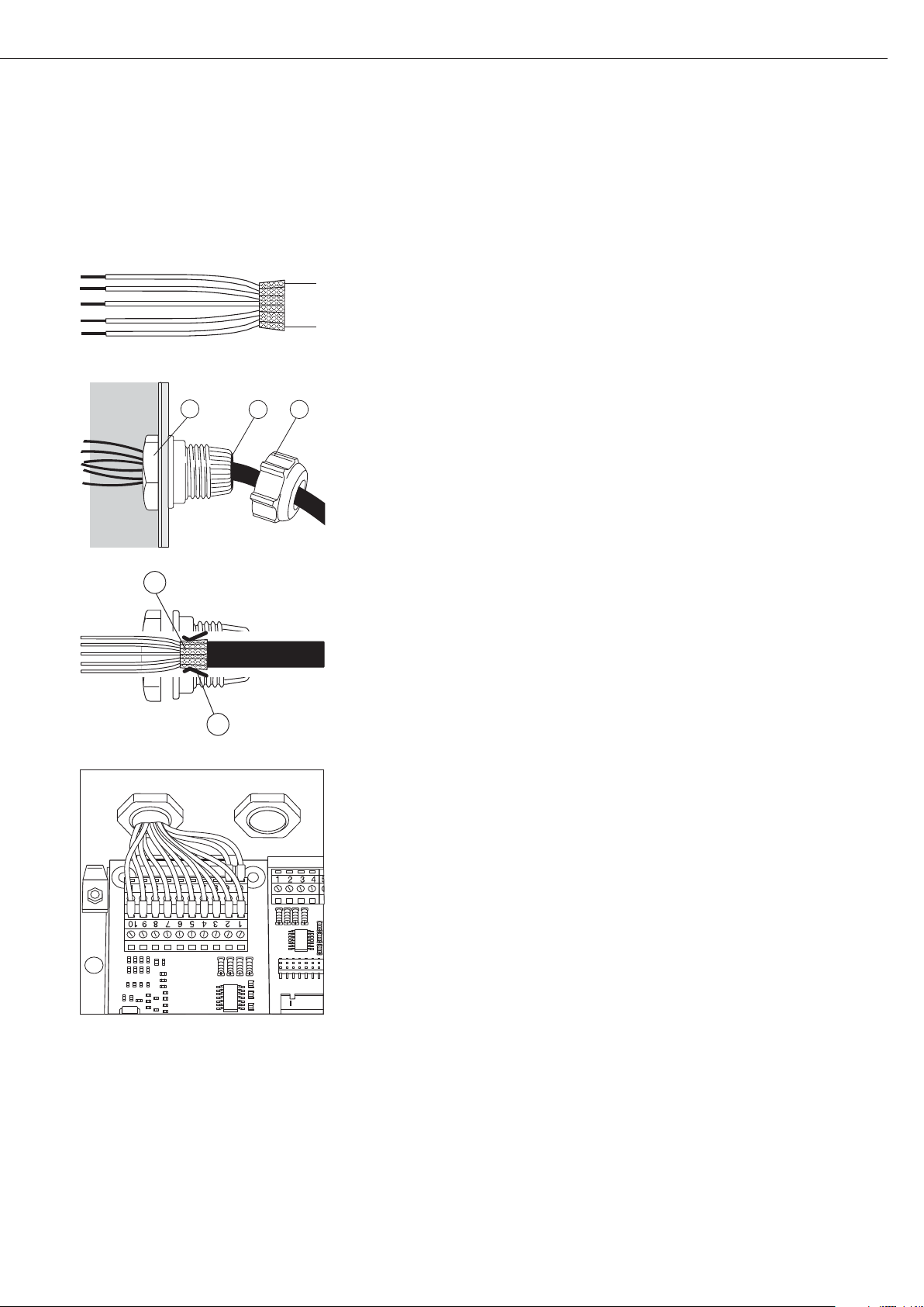
41
Installation du câble d’interface
§ Affectation des broches : voir paragraphe « Affectation des broches de connecteurs ».
§ Relier le câble de raccordement de l’appareil périphérique à l’indicateur à l’aide du passe-
câble à vis.
§ Préparer le câble d’interface :
– Dénuder l’extrémité du câble sur env. 10 cm.
– Raccourcir le blindage à env. 1 cm et le tirer vers l’arrière au-dessus de l’isolation.
– Dénuder les conducteurs du câble de raccordement sur env. 1 cm et y mettre des
embouts.
§ Monter le passe-câble :
!Tous les travaux de raccordement sur le passe-câble à vis doivent être effectués avec le
plus grand soin. Utiliser une clé dynamométrique. Couple de ce passe-câble à vis : 5 Nm.
– Enlever le bouchon d’obturation de l’orifice prévu de l’indicateur.
– Passer le passe-câble à vis ci-joint à travers l’orifice et l’assurer de l’intérieur avec un
contre-écrou (1).
– Passer le câble à travers le passe-câble à vis jusqu’à ce que le blindage (2) soit en contact
avec les bornes (3). Visser l’écrou de serrage (4) jusqu’à ce que la bague d’étanchéité (5)
située entre l’écrou de serrage et le câble forme un petit bourrelet.
– Contrôler le contact des bornes de connexion avec le blindage.
§ Connecter le câble de raccordement :
– Visser les conducteurs aux bornes selon les schémas d’affectation des bornes.
– Affectation des broches : voir page 45.
§ Refermer l’indicateur. Veiller à ce que la bague d’étanchéité entre le boîtier et la plaque
avant soit bien placée.
§ Après avoir fini les travaux de montage, contrôler la protection IP65. A cet effet, utiliser
un manomètre de pression. Pour obtenir davantage d’informations à ce sujet, veuillez
vous adresser au service après-vente Sartorius.
Régler les interfaces COM1 et UniCOM pour l’exploitation
Après la configuration et le montage du module d’interface dans l’indicateur, régler
l’interface UniCOM pour la fonction prévue à l’aide du menu d’exploitation. Voir à ce
propos le chapitre « Réglages COM1 et UniCOM ». Pour obtenir d’autres explications
à ce sujet, voir le chapitre « Réglages » dans le mode d’emploi Midrics.
4
1
5
2
3

42
Configuration du module : YDO01M-485, YDO01M-20MA
YDO01M-485 (options A2 et A3)
Caractéristiques
Le module d’interface YDO01M-485 (interface série RS485/RS422, isolée électriquement1) peut être utilisé en mode d’exploitation RS485 ou RS422.
La configuration pour l’utilisation prévue s’effectue avec huit commutateurs.
En plus du réglage pour l’exploitation prévue comme interface RS485 ou RS422, les
résistances de terminaison (120 O) se trouvant sur la carte de circuits imprimés et les
résistances de polarisation (bias) doivent être activées ou désactivées en fonction du
domaine d’utilisation (réseau ou liaison point à point).
La figure ci-contre montre la disposition des commutateurs. Lorsque le commutateur 1-4
est fermé, l’interface est configurée pour le mode d’exploitation RS422.
Les fonctions suivantes sont disponibles si le commutateur correspondant est fermé
(position : « ON ») :
Fonction (ON = fermé) Commutateur
Résistance de terminaison, côté TX 120O 1 - 1
Résistance BIAS, côté TX (TXD+, pull-up) 680O 1 - 2
Résistance BIAS, côté TX (TXD–, pull-down) 680O 1 - 3
ON : exploitation RS422 | ouvert : exploitation RS485 1 - 4
Résistance de terminaison, côté RX 120O 2 - 1
Résistance BIAS, côté RX (RXD+, pull-up) 680O 2 - 2
Résistance BIAS, côté RX (RXD–, pull-down) 680O 2 - 3
Sans fonction 2 - 4
Remarque concernant la position des interrupteurs
Toujours la même position des interrupteurs :
– les deux interrupteurs 1–2/1–3 sur ON ou OFF
– les deux interrupteurs 2–2/2–3 sur ON ou OFF
Exploitation comme interface RS485 (option A3) :
§ Le commutateur 1-4 pour la commutation vers le mode d’exploitation RS485 doit être
ouvert (réglage d’usine).
§ Le cas échéant, désactiver les résistances bias pour le mode d’exploitation RS485.
A cet effet, ouvrir les commutateurs (réglage d’usine).
Les résistances bias ne doivent être présentes qu’une seule fois dans une liaison de trans-
mission (réseau ou liaison point à point), sinon il y a un risque d’erreur de transmission.
A cet effet, consulter le cas échéant les fiches techniques ou les schémas des connexions
du poste terminal ou des nœuds du réseau. Activer ou désactiver les résistances bias
toujours par deux.
§ La résistance de terminaison (côté TX, commutateur 1 – 1) doit être activée si l’appareil
se trouve à l’une des deux extrémités d’un système de bus RS485 ou s’il est relié à un
autre appareil par une ligne point à point. Une résistance de terminaison de 120 O doit
également se trouver dans le poste terminal. Le cas échéant, activer la résistance de ter-
minaison (120 O) pour le mode d’exploitation RS485 :
fermer les commutateurs 1 - 1 et 2 - 1 (position « ON »).
Exploitation comme interface RS422 (option A2) :
§ Fermer le commutateur 1 - 4 pour la commutation vers le mode d’exploitation RS422
(position « ON »).
§ Le cas échéant, désactiver les résistances bias pour le mode d’exploitation RS422.
A cet effet, ouvrir les commutateurs.
§ Activer la résistance de terminaison du côté RX (commutateur 2 – 1) dans la mesure où
il n’y a pas de résistance de terminaison externe. Toujours désactiver les résistances de
terminaison TX (commutateur 1 – 1).
1
) Le blindage du câble de raccordement est relié d’un côté au boîtier de l’indicateur.
L’indicateur est relié au conducteur de protection.

43
YDA01M-20MA (option A9)
Caractéristiques
Le module d’interface YDA01M-20MA est une sortie analogique. Il peut être utilisé
comme interface de courant (0/4 - 20mA, 0 - 24 mA) ou comme interface de tension
(0 à 10 V). L’alimentation électrique s’effectue de manière interne (isolée
électriquement
1)
.
Le module d’interface peut être réglé sur l’un des quatre états de fonctionnement sui-
vants :
– Interface de tension, 0 à 10 V
– Interface de courant, 0 à 20 mA
– Interface de courant, 4 à 20 mA
– Interface de courant, 0 à 24 mA
La configuration pour l’utilisation prévue a lieu en fermant et en ouvrant des commuta-
teurs. La figure ci-contre montre la disposition des commutateurs.
Le réglage sur l’état de fonctionnement correspondant s’effectue par le réglage des com-
mutateurs 1 et 2 (commutateurs 3 et 4 sans fonction) :
Etat de fonctionnement Commutateur
Interface de tension, 0 à 10 V SW 1–1 : fermé = position « ON »,
SW 1–2 : ouvert
Interface de courant, 0 bis 20 mA SW 1–1 : ouvert,
SW 1–2 : fermé = position « ON »
Interface de courant, 4 à 20 mA SW 1–1 : ouvert, SW 1–2 : ouvert
(réglage d’usine)
Interface de courant, 0 à 24 mA SW 1–1 : fermé = position « ON »,
SW 1–2 : fermé = position « ON »
1
) Le blindage du câble de raccordement est relié d’un côté au boîtier de l’indicateur.
L’indicateur est relié au conducteur de protection.
– Charge max. : 390 ohms
Remarques
– Le blindage du câble de raccordement de l’interface de courant est relié d’un côté au
boîtier de l’indicateur.
– L’indicateur est relié au conducteur de protection.
– Si l’indicateur est alimenté par un accumulateur interne ou externe, l’interface de courant
ne peut pas fonctionner.
§ Le module d’interface YDA01M-20MA est directement connecté à la carte numérique
de circuits imprimés des indicateurs Midrics (MIS..., MW...). Voir à ce sujet le chapitre
« Montage dans l’indicateur ».

44
Exemple : schéma de câblage de base
YDO01M-IO, option A5 :
spécifications
Entrées numériques
–– Nombre : 5
– Niveau bas : de –3V à +5V
– Niveau élevé : de +11V à +30V
– Consommation
électrique max. : 2,6 mA à 15V
– Activation des entrées en
appliquant la tension correspondante.
Sorties numériques
– Nombre : 5
– Conduction électrique
maximale par canal : 100 mA
– Gamme de tension : 0–30 VDC
– Chaque sortie est formée
par un optocoupleur.
YDO01M-EN (Option B9)
Contenu de la livraison
– Module d’interface YDO01M-EN
– Mode d’emploi (ce document)
– Description de l’interface (bus de terrain
pour Modbus TCP)
Montage
Le module d’interface YDO01M-EN
(interface Ethernet) est branché sans
configuration directement sur la carte
numérique de la balance. Voir à cet
effet le chapitre « Montage dans
l’indicateur ». Raccorder le connecteur
mâle du câble Ethernet Sartorius
YCC02RJ45M7 (option M38) au
connecteur femelle du module
d’interface.
Remarque :
!Utiliser uniquement des câbles et des
connecteurs conformément aux spécifi-
cations Ethernet (CAT5 ou supérieur) :
câble Ethernet avec passe-câble à vis
Sartorius, référence YCC02RJ45M7
(option M38)
Le module d’interface ne peut être
utilisé que dans les appareils suivants :
– Indicateur MIS1, MIS2 (IP65)
– Balance complète MW1, MW2 (IP65)
1
23
4
1
0.2A
4
30V
OUTx_high
OUTx_low
Inputx_high
LV1
LV1
LV2
23
Inputx_low
LV2

45
Affectation des broches de connecteurs
COM1
– Interface RS232 : YDO01M-232
(option A11), YDO01M-232CLK (A31) :
affectation des broches de la réglette
à bornes à vis à 8 pôles sur le module
d’interface :
Broche 1 : +12 V : tension de
fonctionnement pour
imprimante Sartorius
Broche 2 : Reset_Out (redémarrage du
périphérique)
Broche 3 : +5 V Out
Broche 4 : Masse (GND)
Broche 5 : Clear to Send (CTS)
Broche 6 : Data Terminal Ready (DTR)
Broche 7 : Entrée de données (R+D)
Broche 8 : Sortie de données (T+D)
UniCOM
– Affectation des broches des deux
réglettes à bornes à vis à 10 pôles sur
le module d’interface :
Interface RS232 :
YDO01M-232CO (option A1) :
Broche 1 : Clear to Send (CTS)
Broche 2 : Data Terminal Ready (DTR)
Broche 3 : Entrée de données (R+D)
Broche 4 : Sortie de données (T+D)
Broche 5 : Masse (GND)
Broche 6 : Universal In
Broche 7 : Sortie de commande
« inférieur »
Broche 8 : Sortie de commande « égal »
Broche 9 : Sortie de commande
« supérieur »
Broche 10 : Sortie de commande « set »
Broche 11 : +12 V : tension de fonc-
tionnement pour impri-
mante Sartorius
Broche 12 : Reset_Out (redémarrage du
périphérique)
Broche 13 : Masse (GND)
Broche 14 : Masse (GND)
Broche 15 : Sortie +5 V
Broche 16 : +5 V activée (par ex. pour
lecteur de code-barre)
Broche 17 : Masse (GND)
Broche 18 : Masse (GND)
Broche 19 : non occupée
Broche 20 : Sortie de tension d’alimen-
tation ext. +15 ... 25 V
Interface E/S numérique :
YDO01M-IO (option A5) :
Broche 1 : Port de sortie ext. 5 : bas
Broche 2 : Port de sortie ext. 5 : élevé
Broche 3 : Port de sortie ext. 4 : bas
Broche 4 : Port de sortie ext. 4 : élevé
Broche 5 : Port de sortie ext. 3 : bas
Broche 6 : Port de sortie ext. 3 : élevé
Broche 7 : Port de sortie ext. 2 : bas
Broche 8 : Port de sortie ext. 2 : élevé
Broche 9 : Port de sortie ext. 1 : bas
Broche 10 : Port de sortie ext. 1 : élevé
Broche 11 : Port d’entrée 5 : bas
Broche 12 : Port d’entrée 5 : élevé
Broche 13 : Port d’entrée 4 : bas
Broche 14 : Port d’entrée 4 : élevé
Broche 15 : Port d’entrée 3 : bas
Broche 16 : Port d’entrée 3 : élevé
Broche 17 : Port d’entrée 2 : bas
Broche 18 : Port d’entrée 2 : élevé
Broche 19 : Port d’entrée 1 : bas
Broche 20 : Port d’entrée 1 : élevé
– Affectation des broches des deux
réglettes à bornes à vis sur le module
d’interface :
YDO01M-485 :
exploitation RS485 (option A2) :
Broche 1 : Données + (T+D-R+D+)
Broche 2 : Données - (T+D-R+D-)
Broche 3 : non occupée
Broche 4 : non occupée
Broche 5 : Signal masse, isolé électri-
quement (GND_GALV)
Broche 6 : Signal masse, isolé électri-
quement (GND_GALV)
Broche 11 : Entrée de tension
d’alimentation ext.
+15 ... 25 V *
Broche 12 : Entrée de tension
d’alimentation ext.
+15 ... 25 V *
Broche 13 : Masse (GND) *
Broche 14 : Masse (GND) *
1
2
3
4
5
66
YDO01M-485 :
exploitation RS422 (option A3) :
Broche 1 :
Sortie de données + (T+D+)
Broche 2 : Sortie de données - (T+D-)
Broche 3 :
Entrée de données + (R+D+)
Broche 4 : Entrée de données - (R+D-)
Broche 5 : Signal masse, isolé électri-
quement (GND_GALV)
Broche 6 : Signal masse, isolé électri-
quement (GND_GALV)
Broche 11 : Entrée de tension
d’alimentation ext.
+15 ... 25 V *
Broche 12 : Entrée de tension
d’alimentation ext.
+15 ... 25 V *
Broche 13 : Masse (GND) *
Broche 14 : Masse (GND) *
* = pas isolé électriquement
YDA01M-20MA
(interface de courant/de tension) :
Réglettes à bornes à vis à 6 pôles sur le
module d’interface
Broche 1 : I_out (+)
pour interface de courant
(0/4 à 20/24 mA)
Broche 2 : I_in (–)
pour interface de courant
(0/4 à 20/24 mA)
Broche 3 : V_out (+)
pour interface de tension,
0 à 10 V
Broche 4 : V_in (–)
pour interface de tension,
0 à 10 V
Broche 5 : GND, isolé électriquement
(masse isolée électriquement)
Broche 6 : GND, isolé électriquement
(masse isolée électriquement)
Affectation des broches de
l’interface Ethernet (RJ45)
YDO01M-EN (option B9) :
Broche 1 : TxD+
Broche 2 : TxDBroche 3 : RxD+
Broche 4 : non occupée
Broche 5 : non occupée
Broche 6 : RxDBroche 7 : non occupée
Broche 8 : non occupée
Châssis : GND
1
2
3
4
5
66
1
2
3
4
5
66

46
Réglages COM1 et UniCOM
Vue d’ensemble du menu d’exploitation pour les interfaces « COM1 » et « UniCOM »
(voir également à ce sujet la vue d’ensemble du menu dans le chapitre « Réglages » du mode d’emploi Midrics)
Appl
Touche Fn
Setup WP-1
COM1 OFF *
DATPROT SBI *
(procès-verbal XBPI-232
de données) SMA
Printer YDP01IS Bande *
Etiquettes
Etiquettes, avance manuelle
YDP02
YDP03
YDP02IS Bande *
Etiquettes
UNI-PRI (imprimante universelle)
YDP04IS Bande *
Etiquettes
Etiquettes, avance manuelle
MEMORY YAM01IS (mémoire alibi)
UniCOM OFF *
DATPROT SBI *
(procès-verbal XBPI-232
de données) XBPI-485
SMA
ETHERNET IP source : 192.168.0.1 *
Nom source
Port d’écoute : 49155 *
Masque sous-réseau : 255.255.255.0 *
IP Gateway : 0.0.0.0 *
IP DNS : 0.0.0.0 *
IP destination : 0.0.0.0 *
Port destination : 49155 *
Protocole TCP *
UDP
Mode SBI –
SRV *
6.1. Edition des données
(serveur)
manuelle/automatique
6.1.1 Manuelle sans stabilité
6.1.2 * Manuelle après stabilité
6.1.4 Automatique sans stabilité
6.1.5 Automatique avec stabilité
6.1.7
Impression de procès-verbal pour PC
7.2. Edition : format des lignes
7.2.1
Pour données brutes : 16 caractères
7.2.2 * Pour autres applic. : 22 caractères
SBI-C/S 6.1. Edition des données
(client) manuelle/automatique
6.1.1 Manuelle sans stabilité
6.1.2 * Manuelle après stabilité
6.1.4 Automatique sans stabilité
6.1.5 Automatique avec stabilité
6.1.7
Impression de procès-verbal pour PC
6.3. Edition autom en fonction
d’un critère de temps
6.3.1 * 1 cycle d’affichage
6.3.2 2 cycles d’affichage
6.3.4 10 cycles d’affichage
6.3.7 100 cycles d’affichage
7.2. Edition : format des lignes
7.2.1
Pour données brutes : 16 caractères
7.2.2 * Pour autres applic. : 22 caractères
xBPI
SMA
Modbus/TCP

47
Setup UniCOM Printer YDP01IS Bande *
Etiquettes
Etiquettes, avance manuelle
YDP02
YDP03
YDP02IS Bande *
Etiquettes
UNI-PRI (imprimante universelle)
YDP04IS Bande *
Etiquettes
Etiquettes, avance manuelle
MEMORY YAM01IS (mémoire alibi)
ANALOG (interface analogique)
CTRL IO: CTR INP : 8. 4. x TTL ; pour YDO01M-232CO, Option A1
entrées/sorties entrées 8. 17. x Isolé électriquement ;
de commande de commande à pour YDO01M-IO, Option A5
8 . 21. x
CTR OUT 8. 24. x Isolé électriquement ;
(sorties de à pour YDO01M-IO, Option A5
commande) 8. 28. x
* = Réglage d’usine

48
Configuration de l’interface
Régler l’interface de données universelle
UniCOM dans le menu d’exploitation de
l’indicateur pour l’état d’exploitation
prévu (raccordement d’un appareil périphérique). La vue éclatée correspondante de l’arbre du menu est représentée à
la page précédente.
Pour obtenir davantage d’explications,
voir le chapitre « Réglages » dans le
mode d’emploi Midrics.
Interface RS485/RS422
Si la carte de circuits imprimés est
configurée pour le mode d’exploitation
RS422, les réglages « SBI », « XBPI-232 »
et SMA peuvent être utilisés dans le
menu.
Interface analogique YDA01M-20MA
Il est possible de configurer les paramètres suivants dans le menu d’exploitation :
– Valeur d’édition (option du menu 8-12) :
8-12-1 : Valeur nette
(réglage d’usine)
8-12-2 : Valeur brute
– Représentation d’erreur (option du
menu 8-13) :
8-13-1 : Niveau élevé (20 mA)
(réglage d’usine)
8-13-2 : Niveau bas (0/4 mA) :
tension de 5 V sur cette interface pendant le fonctionnement
– Mode de sortie (option du menu 8-14) :
8-14-1 : Zéro à charge maximale
(réglage d’usine)
8-14-2 : Valeurs min./max.
– Sortie valeurs min./max.
(option du menu 8-15) :
8-15-1 : Entrée min. (0/4 mA) en kg
8-15-2 : Entrée max. (0/4 mA) en kg
Par le biais de la sélection des valeurs
min./max., il est possible de sélectionner
librement l’étendue de pesée pour
l’édition de 0/4 à 20 mA (0–10 V).
Cette sélection est également valable
pour une balance SBI, mais uniquement
pour la valeur nette.
L’entrée des valeurs min. et max.
s’effectue toujours dans l’unité « Kilogramme ». L’entrée de valeurs de poids
négatives est possible. La valeur min.
peut également être supérieure à la
valeur max. si l’on veut avoir une sortie
de courant descendante.
Exemples :
Courbe de courant ascendante
Valeur min. nette : –1 kg
Valeur max. nette : 4 kg
Courbe de courant descendante pour
balance XBPI
Valeur min. : 5 kg
Valeur max. : 1 kg
Courbe de courant descendante pour
balance SBI
Valeur min. : 5 kg
Valeur max. : 1 kg
Interface Ethernet
Entrer les nombres requis dans le menu
« UNICOM » sous « ETHERNET » IP
source, Port d’écoute, etc. Sous « Nom
source », il est possible d’utiliser des
lettres et des chiffres. Entrer au
maximum 15 caractères. Entrer le nom
source en alternative à l’IP source.
Numéros de port
Domaine de validité : 0 – 65535
Etant donné que beaucoup de ports
sont déjà affectés jusqu’à 49150, nous
conseillons d’utiliser des numéros de
port supérieurs à 49150. Cela n’est pas
valable pour ModBus/TCP car le numéro
de port 502 est utilisé ici (voir le mode
d’emploi du module bus de terrain).

49
Interface Ethernet : Initialisation
Affichage : initialisation terminée
Si l’initialisation du module Ethernet
a été terminée avec succès,
Le symbole « » apparaît.
Le module de réseau
est initialisé
Si l’initialisation n’est pas réussie,
aucun symbole n’apparaît. Ce symbole
n’apporte aucune indication sur l’état
de connexion avec le réseau.
Connexions TCP :
Dans le mode d’exploitation SBI-C/S,
l’indicateur Midrics interrompt toujours
lui-même la connexion au bout dune
seconde.
Dans les autres modes d’exploitation
SBI-SRV, SMA, XBPI, ModBus/TCP,
la connexion demeure jusqu’à ce que
l’ordinateur (client) l’interrompe. On ne
peut établir qu’une seule connexion
à la fois.
Interface Ethernet : caractéristiques
Source IP : Adresse IP de l’indicateur Midrics
Si l’adresse 0.0.0.0 est sélectionnée, une adresse IP doit être attribuée
de manière dynamique par un serveur DHCP disponible dans le réseau.
Il faut alors effectuer une entrée dans Nom source.
Nom source : Ce paramètre est également possible pour IP source. Il est possible d’entrer
un nom de 15 caractères max. pour identifier l’indicateur Midrics. Il faut
alors régler l’adresse 0.0.0.0 sous Source IP. Le nom est communiqué
au Domain-Name-Server (DNS) si
- une adresse IP a été entrée sous IP DNS
ou
- une adresse IP a été attribuée par un serveur DHCP.
Port appareil : Numéro de port sur lequel Midrics se met à l’écoute pour le mode serveur.
Masque
sous-réseau : Masque de l’adresse IP pour activer des adresses dans un sous-réseau.
Si le masque a été attribué par un serveur DHCP, il faut entrer 0.0.0.0.
IP gateway : Adresse IP d’un gateway
Utiliser la zone IP destination pour accéder au serveur souhaité dans un
autre réseau. Si l’adresse IP doit être attribuée de manière dynamique par
un serveur DHCP, il faut entrer 0.0.0.0.
IP destination : Adresse du serveur qui doit recevoir les données de Midrics.
Cela est important si Midrics fonctionne en tant que client dans le mode
SBI et si l’édition automatique des données est activée. Si l’on utilise UDP,
il faut également entrer une adresse IP ici.
Port destination : Numéro de port par lequel le serveur avec l’IP destination reçoit les
données Midrics.
Protocole : Sélectionner le protocole de transport permettant de transmettre les
données via Ethernet.
Il est possible de choisir entre :
– TCP : orienté connexion ; sécurité élevée des données
ou
– UDP : sans connexion (ne fonctionne pas avec Modbus/TCP)
Mode : Sélectionner les formats utilisés pour intégrer les données de l’utilisateur
dans TCP ou dans UDP (par ex. SMA tunnelle des données via Ethernet
lorsqu’on utilise TCP ou UDP).
Avec les protocoles SBI-SRV, XBPI et SMA, Midrics fonctionne exclusive-
ment comme serveur. Avec SBI-C/S, Midrics est à la fois serveur et client.
Dans ce cas, Midrics agit en tant que client lorsque l’on appuie sur la touche
p [Print] et lorsque l’édition automatique des données est activée.
Pour le mode OPC, régler le mode « Server SBI ». Dans les autres cas,
Midrics agit en tant que serveur. Lorsqu’on utilise ModBus/TCP, Midrics
fonctionne exclusivement comme serveur (voir également le mode
d’emploi du module bus de terrain).
Réponse
après la mise
sous tension : Si le module d’interface est activé, il se peut que l’affichage de la valeur
pondérale ait besoin de 20 secondes supplémentaires pour répondre.

50
Synchronisation
Des «messages» constitués de caractères
ASCII sont transmis par l’intermédiaire
de l’interface pour l’échange de données entre l’indicateur et un ordinateur.
Pour un échange de données exempt
d’erreur, les paramètres : vitesse de
transmission, parité et handshake ainsi
que le format des caractères doivent
être identiques pour les deux interfaces.
Il est possible de procéder à une adaptation de l’indicateur par l’intermédiaire
des réglages correspondants dans le
setup (menu) de façon à adapter la liaison au périphérique. Outre ces réglages,
il est possible de subordonner l’édition
des données de l’indicateur à différentes conditions. Ces conditions sont
décrites dans les programmes d’application correspondants.
Une interface de données ouverte (pas
d’appareils périphériques raccordés) ne
provoque pas de messages d’erreur.
Handshake (protocole de transfert)
L’interface de la balance est équipée
d’un registre d’émission et d’un registre
de réception. Il est possible, dans le
setup de l’indicateur de choisir le mode
de fonctionnement du mode de contrôle (handshake) :
– Handshake hardware (CTS/DTR)
– Handshake logiciel (XON, XOFF)
Handshake hardware
Avec le handshake hardware avec
une interface à 4 fils, il est possible
d’envoyer 1 caractère après CTS.
Handshake logiciel
Le handshake logiciel est commandé
par XON et XOFF. Un XON doit être
émis par un appareil périphérique lors
de sa mise sous tension de façon à permettre éventuellement à un autre périphérique d’échanger ses données.
Le déroulement de la transmission des
données a donc lieu comme suit :
Balance ––– octet –––> Ordinateur
(émet- ––– octet –––> (récepteur)
teur)
––– octet –––>
––– octet –––>
<–– XOFF –––
––– octet –––>
––– octet –––>
...
(Pause)
...
<–– XON –––
––– octet –––>
––– octet –––>
––– octet –––>
––– octet –––>
Emetteur
Un XOFF reçu empêche la poursuite de
l’émission de caractères. Un XON reçu
a pour effet de libérer l’émetteur.
Récepteur
Afin de ne pas trop surcharger la transmission avec des caractères de contrôle,
la libération par XON ne se fait que
lorsque le registre est presque vidé.

51
Interfaces de données
Configurer l’interface de
données comme interface de
communication (datprot)
L’interface est configurée comme interface de communication dans le menu
setup sous COM1 ou UniCOM, « Procèsverbaux de données » (datprot).
Communication SBI
Il s’agit d’une interface ASCII simple.
Les options du menu 6-1 et 6-3 permettent de régler la manière d’éditer les
données :
– Edition manuelle d’une valeur affichée
avec ou sans stabilité (options du menu
6-1-1 et 6-1-2)
– Edition automatique d’une valeur affi-
chée avec ou sans stabilité (options du
menu 6-1-4 et 6-1-5) en fonction du
nombre de cycles d’affichage. L’option
du menu 6-3 permet de régler le
nombre d’intervalles d’affichage pour
l’édition.
– Edition d’un procès-verbal configurable.
L’édition est associée à l’option du
menu « Procès-verbaux d’impression »
(prtprot).
A l’exception de l’édition d’un procèsverbal d’impression configurable, la
valeur actuelle affichée (valeur de pesée
avec unité, valeur calculée, affichage de
chiffres et de lettres) est éditée.
Communication SMA
Protocole de communication standardisé de la Scale Manufacturers Association
Format d’entrée des données
(commandes)
L’ordinateur connecté par l’intermédiaire de l’interface de données (communication SBI) peut envoyer des ordres à
l’indicateur afin de commander des
fonctions de la balance et des fonctions
des programmes d’application.
Tous les ordres ont un format de début
et de fin commun (format d’entrée des
données) : ils commencent par le caractère ESC (ASCII : 27) et se terminent par
la chaîne de caractères CR (ASCII : 13)
et LF (ASCII : 10). Leur longueur varie
entre au minimum 4 caractères
(1 caractère d’ordre) et au maximum
7 caractères (4 caractères d’ordre).
Les ordres représentés dans le tableau
suivant doivent à chaque fois être complétés par le format de début et de fin
ESC ... CR LF.
Exemple : l’ordre d’impression « P »
(« envoyer valeur d’affichage ») doit être
envoyé à l’indicateur. Pour cela, la chaîne de caractères « ESC P CR LF » est
envoyée.
Ordre Signification
K Mode de pesée 1
L Mode de pesée 2
M Mode de pesée 3
N Mode de pesée 4
O Bloquer le clavier
P Envoyer la valeur d’affichage
à l’interface de données
R Libérer le clavier
T Tarage et mise à zéro
(fonction combinée de tare)
f3_ Mise à zéro (zéro),
comme ordre « kZE_ »
f4_ Tarage (sans mise à zéro),
comme ordre « kT_ »
kF1_ F1 : Déclencher la touche k
kF2_ F2 : Déclencher la touche c
(seulement sur le modèle
Midrics 2)
kF3_ F3 : Déclencher la touche r
(seulement sur le modèle
Midrics 2)
kF4_ F4 : Déclencher la touche O
(seulement sur le modèle
Midrics 2)
kF5_ F5 : Déclencher la touche w
(seulement sur le modèle
Midrics 2)
Ordre Signification
kF6_ F6 : Déclencher la touche I
(seulement sur le modèle
Midrics 2)
KF7_ Touche d
kCF_ CF : Déclencher la touche c
(seulement sur le modèle
Midrics 2)
kP_ Déclencher la touche p
Impression sur l’interface
d’imprimante
kT_ Déclencher la touche )
(tarage)
kZE_ Déclencher la touche (
(mise à zéro)
x1_ Edition du type de la plate-
forme de pesée actuelle,
exemple : « LP6200S-0C »
x2_ Edition du numéro de série
de la plate-forme de pesée
actuelle,
exemple : « 0012345678 »
x3_ Edition de la version du logi-
ciel de la plate-forme de pesée
actuelle,
exemple : « 00-20-04 »
z1_ Entrée : ligne d’en-tête 1 du
procès-verbal
z2_ Entrée : ligne d’en-tête 2 du
procès-verbal
txx...x_ xx...x : Entrée de lettres
Longueur selon entrée (seulement sur le modèle Midrics 2)
Le caractère « _ » (sous-tiret) est le
caractère ASCII 95 décimal.
Format pour l’entrée des lignes d’entête de procès-verbal : « ESC z x a ... a _
CR LF » avec x=1 ou 2 et a ... a : 1 à 20
caractères pour la ligne d’en-tête x, suivis des caractères sous-tiret, CR et LF.

52
Format de sortie des données
Une ligne imprimée comprend au maximum 22 caractères
(20 caractères imprimables plus deux caractères de contrôle).
Les 6 premiers caractères servent à identifier la valeur qui suit.
L’identification peut être désactivée sous l’option du menu 7-2
si bien que la ligne imprimée comprend alors 16 caractères
(14 caractères imprimables plus deux caractères de contrôle).
Exemples :
+ 235 pcs sans identification
Qnt + 235 pcs avec identification
Les caractères qui n’apparaissent pas à l’affichage sont édités
sous la forme d’espaces (blancs). Pour les nombres sans point
décimal, aucun point décimal n’est édité
Format de sortie avec 16 caractères
(sans identification)
Exploitation normale :
Pos. 123456789101112131415 16
+* AAAAAAAA* U U U CR LF
ou - * AAAAAAAA* U U U CR LF
ou **************CR LF
+- : Signe +/–
* : Espace (blanc)
A : Caractère de l’affichage
(au max. 7 chiffres et point décimal)
U : Caractère pour l’unité de mesure
(1 à 3 lettres, suivies de 2 à 0 espaces)
CR : Carriage Return (retour chariot)
LF : Line Feed (saut de ligne)
Exploitation spéciale :
Pos. 12345678910111213141516
******––******CR LF
ou ******H*******CR LF
ou ******HH******CR LF
ou ******L*******CR LF
ou ******LL******CR LF
ou ******C*******CR LF
* : Espace (blanc)
– – : Lecture finale
H : Surcharge
HH : Surcharge contrôle +/–
L : Sous-charge
LL : Sous-charge contrôle +/–
C : Ajustage
Message d’erreur :
Pos. 12345678910111213141516
***Err**##****CRLF
ou ***Err*###****CRLF
* : Espace (blanc)
# : Chiffre (numéro de l’erreur à 2 ou 3 chiffres)
Exemple (édition de la valeur de pesée +1255,7 g) :
Pos. 12345678910111213141516
+** * 1255. 7* g* * CRLF
Position 1 : Signe +, – ou espace (blanc)
Position 2 : Espace (blanc)
Position 3-10 : Valeur pondérale avec point décimal. Les zéros
précédents sont édités sous la forme de blancs.
Position 11 : Espace (blanc)
Position 12-14 : Caractère pour l’unité de mesure ou espace
Position 15 : Carriage Return (retour chariot)
Position 16 : Line Feed (saut de ligne)
Format de sortie avec 22 caractères
(avec identification)
Exploitation normale :
Pos. 12345678910111213141516171819202122
IIIIII+*AAAAAAAA* U U U CRLF
ou IIIIII-*AAAAAAAA* U U U CRLF
ou ********************CRLF
I : Caractère d’identification, rempli justifié à droite avec
espace
+- : Signe +/–
* : Espace (blanc)
A : Caractère de l’affichage (au max. 7 chiffres et point décimal)
U : Caractère pour l’unité de mesure (1 à 3 lettres, suivies de
2 à 0 espaces)
CR : Carriage Return (retour chariot)
LF : Line Feed (saut de ligne)
Exploitation spéciale :
Pos. 12345678910111213141516171819202122
Stat********––******CRLF
ou Stat********H*******CRLF
ou Stat********HH******CRLF
ou Stat********L*******CRLF
ou Stat********LL******CRLF
ou Stat********C*******CRLF
* : Espace (blanc) – – : Pesée finale
H : Surcharge HH : Surcharge contrôle +/–
L : Sous-charge LL : Sous-charge contrôle +/–
C : Ajustage

53
Interfaces de données
Procès-verbal BPF
Lorsque l’option du menu est activée, le
procès-verbal d’impression est complété
par un en-tête et un bas de page BPF
avant et après le résultat de mesure
(BPF : Bonnes Pratiques de Fabrication).
L’en-tête BPF est imprimé avant le premier résultat de mesure. Le bas de page
BPF est imprimé soit après chaque
résultat (procès-verbal BPF toujours
pour 1 résultat de mesure, 7-11-2) ou
après le dernier résultat de mesure
d’une série de résultats (procès-verbal
BPF toujours pour plusieurs résultats de
mesure, 7-11-3). Une série de résultats
de mesure est achevée lorsque l’on
appuie longuement sur la touche p.
Dans ce cas, le symbole A est affiché
après l’impression de l’en-tête BPF jusqu’à l’impression du bas de page BPF.
Une impression BPF a toujours lieu
automatiquement à la fin d’un processus d’ajustage.
Lors d’impressions conformes aux BPF
sur une imprimante d’étiquettes sous le
réglage du menu 7-11-3, le rapport
entre l’en-tête et le bas de page BPF est
perdu (impression sur plusieurs étiquettes). Des impressions BPF sur des
imprimantes d’étiquettes devraient donc
logiquement être effectuées uniquement sous le réglage du menu 7-11-2.
Ci-dessous sont représentés un exemple d’en-tête et un exemple de bas de page de procèsverbal BPF :
------------------- Ligne en pointillé
14.01.2007 09:43 Date/heure
1
)
Typ MIS2 Type Midrics
Ser.no. 12345678 N° de série Midrics
Vers. 1.1007.12.1 Vers. logiciel applic.
BVers. 01-25-01 Vers. logiciel base
------------------- Ligne en pointillé
Bas de page BPF :
------------------- Ligne en pointillé
14.01.2007 09:45 Date/heure
1
)
Name: Emplacement signature
Interligne
------------------- Ligne en pointillé
1
) YDO01M-232, option A31 nécessaire

54
Uso previsto
L'uscita dati YD.01M-... è destinata
all’installazione in indicatori e bilance
complete modello Midrics MIS..., MW...
come interfaccia standard opzionale
COM1 o come interfaccia dati universale UniCOM.
Per COM1:
– YDO01M-232 (Opzione A11):
interfaccia dati bidirezionale RS232.
Il modulo YDO01M-232 permette il
collegamento di diverse stampanti
(YDP02IS, YDP03, YDP04IS, YDP12IS,
stampante universale), lo scambio di
dati con un PC (modalità SBI, xBPI
o SMA).
– Collegamento di una memoria alibi
– Adattatore Bluetooth YBT01.
– Display supplementare YRD02Z.
– Cavo adattatore USB per il collega-
mento di un PC tramite USB YCC01IS.
– YDO01M-232CLK «Orologio» (Opzione
A31): come RS232 standard, ma con
orologio per data/ora
Per UniCOM:
– YDO01M-232CO (Opzione A1):
come RS232 standard RS232 ed in più
I/O digitale (TTL/5V)
– YDO01M-485 (Opzioni A2 e A3):
interfaccia dati bidirezionale, isolata
elettricamente, utilizzabile a scelta in
modalità RS422 (Opzione A2) oppure
in modalità RS485 (Opzione A3).
Il modulo YDO01M-485 permette un
collegamento in rete di fino a 32 bilance/indicatori Midrics tramite bus XBPI.
– YDA01M-20MA (Opzione A9):
uscita analogica, utilizzabile a scelta
come interfaccia di corrente (0/4 - 20 mA,
0 - 24 mA) oppure come interfaccia di
tensione (0 - 10 V).
Il modulo YDA01-20MA permette il
collegamento di un PLC o di un display
analogico esterno.
– YDO01M-IO (Opzione A5):
modulo di ingresso/uscita digitale per il
collegamento di Midrics a controllori
esterni.
– YDO01M-EN (Opzione B9):
interfaccia Ethernet (per es. connessione
ad un PLC o PC).
Spiegazione dei simboli
In questo manuale di istruzioni sono
impiegati i seguenti simboli:
§ Indica le operazioni richieste per un
corretto utilizzo
$ Indica le operazioni da eseguirsi solo
in certe condizioni
> Descrive l’effetto di un’operazione
! Indica un pericolo
Indice
54 Uso previsto
54 Indice
55 Montaggio nell'indicatore
55 Installazione della scheda COM1
56 Installazione della scheda UniCOM
58 Installazione del cavo d'interfaccia
59 Configurazione del modulo:
YDO01M-485, YDA01M-20MA
61 YDO01M-IO: specificazioni
61 YDO01M-EN
62 Schema di assegnazione dei pin
62 COM1
62 UniCOM
63 Impostazioni per COM1 e UniCOM
67 Sincronizzazione
68 Interfacce dati
68 Formato dei dati in ingresso
(comandi)
69 Formato dei dati in uscita
70 Protocollo GMP

55
Montaggio nell'indicatore
Montaggio
Il montaggio del modulo di interfaccia nell’indicatore Midrics (in aggiunta il montaggio
del passacavo a vite e il collegamento del cavo alla morsettiera a vite) è necessario solo se
l’indicatore Midrics non è stato dotato in fabbrica su richiesta del Cliente dell’uscita dati
corrispondente.
Avvertenze:
§ Il montaggio del modulo di interfaccia deve essere eseguito da un tecnico Sartorius quali-
ficato e autorizzato.
§ Protezione IP65:
Utilizzare il cavo di collegamento con passacavo a vite per il modulo di interfaccia interessato (accessorio).
!Prima d’iniziare i lavori scollegare l’apparecchio dalla rete.
!In caso d’installazione impropria decade il diritto alla garanzia.
!I lavori che influiscono sul grado di protezione IP65 devono essere eseguiti con la massi-
ma cura. Il passacavo a vite (protezione IP65) per il collegamento dell’interfaccia all’indicatore è chiuso da un tappo cieco. Eseguire con molta cura tutti i lavori sul passacavo a
vite.
§ Rimozione del pannello anteriore: svitare le 4 viti del pannello anteriore.
Installazione della scheda COM1:
§ Svitare la vite di fissaggio.

56
§ Avvitare il perno distanziatore.
§ Inserire il porta-scheda
§ Innestare il modulo di interfaccia (YDO01M-232 e YDO01M-232CLK) sulla scheda
digitale dell’indicatore Midrics. A tale scopo innestare i connettori femmina del modulo
interfaccia nei corrispondenti connettori maschi della scheda digitale.
§ Fissare con la vite il modulo d’interfaccia.
I moduli d'interfaccia sono dotati di proprie morsettiere a vite. Allacciare il cavo di
collegamento alle morsettiere.
Installazione della scheda UniCOM:
§ Svitare la 2 vite di fissaggio.
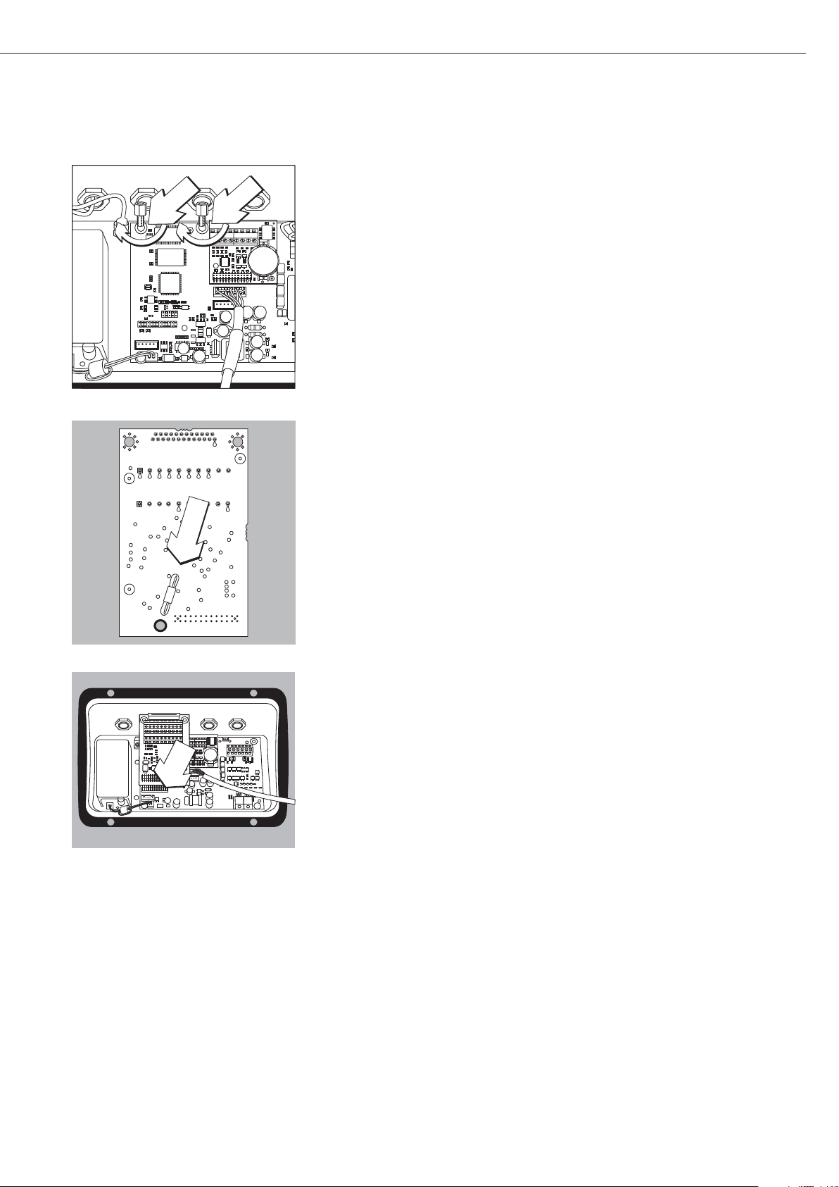
57
§ Avvitare i 2 perni distanziatore.
§ Inserire il porta-scheda
§ Innestare il modulo di interfaccia (YDO01M-232CO, YDO01M-485, YDA01M-20MA
o YDO01M-IO oppure YDO01M-EN) sulla scheda digitale dell’indicatore Midrics.
A tale scopo innestare i connettori femmina del modulo interfaccia nei corrispondenti
connettori maschi della scheda digitale.
§ Fissare con la 2 viti il modulo d’interfaccia.
I moduli d'interfaccia sono dotati di proprie morsettiere a vite. Connettere il cavo di
collegamento alle morsettiere.

58
Installazione del cavo d'interfaccia
§ Assegnazione degli attacchi: vedi sezione «Schema di assegnazione dei pin».
§ Connettere il cavo di collegamento della periferica con l’indicatore mediante un passacavo
a vite.
§ Preparazione del cavo d'interfaccia:
– Togliere l’isolamento protettivo dall’estremità del cavo, circa 10 cm
– Ridurre la schermatura di circa 1 cm e spingerla all'indietro sopra l'isolamento
– Togliere di 1 cm circa l’isolamento dei fili del cavo e applicare le boccole
§ Montaggio del pressacavo:
!Eseguire con molta cura tutti i lavori sul passacavo a vite. Utilizzare una chiave dinamo-
metrica. Coppia di serraggio del passacavo a vite: 5 Nm.
– Togliere il tappo cieco dal foro presente sull’indicatore
– Inserire il passacavo a vite attraverso il foro e avvitare il controdado (1) dall'interno.
– Inserire il cavo attraverso il passacavo fino al punto in cui schermatura (2) è a contatto
con i morsetti (3). Serrare il dado di compressione (4) fino a quando l’anello di tenuta (5),
posto tra il dado di compressione e il cavo, forma un piccolo rigonfiamento.
– Controllare che i morsetti facciano contatto con la schermatura.
§ Montare il cavo di collegamento:
– Avvitare saldamente i fili ai morsetti secondo lo schema di assegnazione dei morsetti.
– Schemi di assegnazioni a pagina 62.
§ Chiudere di nuovo l’indicatore. Prestare attenzione al corretto posizionamento dell’anello
di tenuta tra l’alloggiamento e il pannello anteriore.
§ Al termine dei lavori di montaggio controllare la protezione IP65. Utilizzare allo scopo un
manometro. Per maggiori informazioni in merito rivolgersi al Servizio Assistenza Sartorius.
Impostazione dell’interfaccia COM1 e UniCOM per il funzionamento
Dopo aver configurato e montato il modulo interfaccia nell’indicatore, impostare le
funzioni previste dell’interfaccia UniCOM con l’ausilio del menu operativo. Vedere in
merito il capitolo «Impostazioni COM1 e UniCOM». Per maggiori informazioni si rimanda
al capitolo «Impostazioni» delle Istruzioni per l’uso Midrics.
4
1
5
2
3
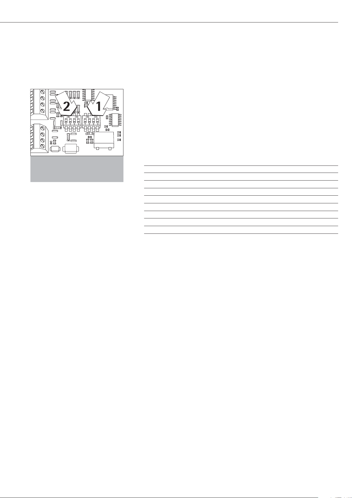
59
Configurazioni dei moduli YDO01m-485, YDO01M-20MA
YDO01M-485 (Opzioni A2 e A3)
Caratteristiche
Il modulo di interfaccia YDO01M-485 (interfaccia seriale RS485/RS422, con separazione
galvanica 1) può essere utilizzato in modalità RS485 o RS422. La configurazione per il
tipo d’impiego previsto si effettua con otto interruttori. In aggiunta all’impostazione
della modalità prevista (interfaccia RS485 o RS422) occorre anche, in funzione del campo
d’impiego (rete o collegamento punto-punto), attivare o disattivare le resistenze di terminazione (120 O) e di bias presenti sulla scheda.
La disposizione dei interruttori può essere desunta dal disegno riportato a lato.
Se l'interruttore 1-4 è chiuso, l’interfaccia è configurata per la modalità RS422.
Le seguenti funzioni sono disponibili quando l'interruttore corrispondente è chiuso
(posizione: «ON»):
Funzione (ON = chiuso) Interruttore
Resistenza terminale, lato TX 120O 1 - 1
Resistenza BIAS, lato TX (TXD+, Pull-Up) 680O 1 - 2
Resistenza BIAS, lato TX (TXD–, Pull-Down) 680O 1 - 3
ON: modalità RS422 | aperto: modalità RS485 1 - 4
Resistenza terminale, lato RX 120O 2 - 1
Resistenza BIAS, lato RX (RXD+, Pull-Up) 680O 2 - 2
Resistenza BIAS, lato RX (RXD–, Pull-Down) 680O 2 - 3
Senza funzione 2 - 4
Indicazione per la posizione degli interruttori
Sempre la stessa posizione degli interruttori:
– entrambi gli interruttori 1–2/1–3 ON o OFF
– entrambi gli interruttori 2–2/2–3 su ON o OFF
Funzionamento come interfaccia RS485 (Opzione A3):
§ L'interruttore 1-4 per la commutazione nella modalità RS485 deve essere aperto
(impostazione di fabbrica).
§ Eventualmente disattivare entrambe le resistenze di bias per la modalità RS485 aprendo
allo scopo l'interruttore (impostazione di fabbrica).
Le resistenze di bias non devono comparire più di una volta sullo stesso tratto di trasmis-
sione (rete o collegamento punto-punto), poiché in caso contrario possono verificarsi
errori di trasmissione. Consultare in proposito le schede tecniche o la documentazione
di connessione del dispositivo al capo opposto del collegamento o dei nodi di rete.
Attivare o disattivare le resistenze di bias sempre a coppie.
§ Eventualmente attivare la resistenza di terminazione (lato TX, interruttore 1 – 1) se il
dispositivo si trova ad uno dei due capi di un sistema bus RS485 o se è collegato punto-
punto con un altro dispositivo. Anche sul capo opposto deve essere disponibile una
resistenza di terminazione di 120 O. Se necessario attivare la resistenza terminale (120 O)
per la modalità RS485:
chiudere gli interruttori 1 - 1 e 2 - 1 (posizione «ON»)
Funzionamento come interfaccia RS422 (Opzione A2):
§ Chiudere l'interruttore 1-4 per la commutazione nella modalità RS422 (posizione «ON»)
§ Se necessario disattivare le resistenze bias per la modalità RS422 aprendo allo scopo gli
interruttori.
§ Attivare la resistenza terminale del lato RX (interruttore 2 – 1) se non è disponibile una
resistenza terminale esterna. Disattivare sempre le resistenze di terminazione TX (interrut-
tore 1 – 1).
1
) La schermatura del cavo di collegamento è collegata da un lato con l’alloggiamento dell’indicatore.
L’indicatore è collegato al conduttore di protezione.

60
YDA01M-20MA (Opzione A9)
Caratteristiche
Il modulo di interfaccia YDA01M-20MA è un’uscita analogica. Esso può essere utilizzato
come interfaccia di corrente (0/4 - 20mA, 0 - 24 mA) o di tensione (0 - 10 V).
L’alimentazione avviene internamente (isolata elettricamente
1)
).
Il modulo di interfaccia può essere configurato per uno dei quattro seguenti stati
operativi:
– interfaccia di tensione, 0 - 10 V
– interfaccia di corrente, 0 - 20 mA
– interfaccia di corrente, 4 - 20 mA
– interfaccia di corrente, 0 - 24 mA
La configurazione per il tipo di impiego previsto si effettua chiudendo o aprendo gli
interruttori. La disposizione degli interruttori può essere desunta dal disegno riportato
a lato.
Lo stato operativo corrispondente si effettua impostando gli interruttori 1 e 2
(gli interruttori 3 e 4 sono senza funzione):
Stato operativo Interruttore
Interfaccia di tensione, 0 - 10 V SW 1–1: chiuso = posizione «ON»,
SW 1–2: aperto
Interfaccia di corrente, 0 – 20 mA SW 1–1: aperto,
SW 1–2: chiuso = posizione «ON»
Interfaccia di corrente, 4 – 20 mA SW 1–1: aperto, SW 1–2: aperto
(impostazione di fabbrica)
Interfaccia di corrente, 0 – 24 mA SW 1–1: chiuso = posizione «ON»
SW 1–2: chiuso = posizione «ON»
1
) La schermatura del cavo di collegamento è collegata da un lato con l’alloggiamento dell’indicatore.
L’indicatore è collegato al conduttore di protezione.
– Carico max.: 390 Ohm
Avvertenze
– La schermatura del cavo di collegamento dell’interfaccia di corrente è collegata da un
lato con l’alloggiamento dell’indicatore.
– L’indicatore è collegato al conduttore di protezione.
– Se l’indicatore è alimentato da una batteria ricaricabile interna o esterna, non è possibile
il funzionamento dell’interfaccia di corrente.
§ Il modulo interfaccia YDA01M-20MA si innesta direttamente sulla scheda digitale
degli indicatori Midrics (MIS..., MW...). Vedere in proposito il capitolo «Montaggio
nell’indicatore».

61
Esempio: schema di cablaggio base
YDO01M-IO, Opzione A5:
specificazioni
Ingressi digitali
– Numero: 5
– Livello Low: –3V - +5V
– Livello High: +11V - +30V
– Potenza assorbita
max.: 2,6 mA a 15V
– Attivazione degli ingressi
applicando la tensione corrispondente.
Uscite digitali
– Numero: 5
– Flusso di corrente max.
per ogni canale: 100 mA
– Campo tensione 0–30 Vdc
– Ogni uscita è formata per mezzo
di un optoaccoppiatore.
YDO01M-EN (Opzione B9)
Equipaggiamento fornito
– Modulo di interfaccia YDO01M-EN
– Istruzioni per l’uso (questo manuale)
– Descrizione dell’interfaccia (bus di
campo) per Modbus TCP
Montaggio
Il modulo di interfaccia YDO01M-EN
(interfaccia Ethernet) viene inserito
senza configurazione direttamente sulla
scheda digitale della bilancia. Si veda
a riguardo il capitolo «Montaggio
nell’indicatore». Inserire il connettore
maschio del cavo Sartorius Ethernet
YCC02-RJ45M7 (opzione M38) nel
connettore femmina del modulo
d’interfaccia.
Avvertenza:
!Utilizzare solo cavi e connettori
conformi alla specifica Ethernet (CAT5
oppure più alta): cavo Ethernet con
passacavo a vite codice d’ordinazione
Sartorius YCC02-RJ45M7 (opzione
M38). Il modulo d’interfaccia può essere
usato solo nei seguenti apparecchi:
– Indicatore MIS1, MIS2 (IP65)
– Bilancia completa MW1, MW2 (IP65)
1
23
4
1
0.2A
4
30V
OUTx_high
OUTx_low
Inputx_high
LV1
LV1
LV2
23
Inputx_low
LV2

62
Schema di assegnazione dei pin
COM1
– Interfaccia RS232: YDO01M-232
(Opzione A11), YDO01M-232CLK (A31):
Assegnazione dei pin della morsettiera
a 8 pin sul modulo d'interfaccia:
Pin 1: +12 V: tensione d'esercizio per
stampante Sartorius
Pin 2: Reset_Out
(riavvio periferica)
Pin 3: +5 V Out
Pin 4: massa (GND)
Pin 5: Clear to Send (CTS)
Pin 6: Data Terminal Ready (DTR)
Pin 7: Ingresso dati (R+D)
Pin 8: Uscita dati (T+D)
UniCOM
– Assegnazione dei pin delle due morset-
tiere a 10 pin sul modulo d'interfaccia:
Interfaccia RS232: YDO01M-232CO
(Opzione A1):
Pin 1: Clear to Send (CTS)
Pin 2: Data Terminal Ready (DTR)
Pin 3: ingresso dati (R+D)
Pin 4: uscita dati (T+D)
Pin 5: massa (GND)
Pin 6: Universal In
Pin 7: uscita di controllo «più leggero»
Pin 8: uscita di controllo «uguale»
Pin 9: uscita di controllo «più pesante»
Pin 10: uscita di controllo «set»
Pin 11: +12 V: tensione d'esercizio per
stampante Sartorius
Pin 12: Reset_Out (riavvio periferica)
Pin 13: massa (GND)
Pin 14: massa (GND)
Pin 15: uscita +5 V
Pin 16: +5 V attivato (per es. per
lettore di codici a barre)
Pin 17: massa (GND)
Pin 18: massa (GND)
Pin 19: non assegnato
Pin 20: uscita esterna tensione di
alimentazione +15 ... 25 V
Interfaccia I/O digitale:
YDO01M-IO (Opzione A5):
Pin 1: porta in uscita esterna 5: low
Pin 2: porta in uscita esterna 5: high
Pin 3: porta in uscita esterna 4: low
Pin 4: porta in uscita esterna 4: high
Pin 5: porta in uscita esterna 3: low
Pin 6: porta in uscita esterna 3: high
Pin 7: porta in uscita esterna 2: low
Pin 8: porta in uscita esterna 2: high
Pin 9: porta in uscita esterna 1: low
Pin 10: porta in uscita esterna 1: high
Pin 11: porta in ingresso 5: low
Pin 12: porta in ingresso 5: high
Pin 13: porta in ingresso 4: low
Pin 14: porta in ingresso 4: high
Pin 15: porta in ingresso 3: low
Pin 16: porta in ingresso 3: high
Pin 17: porta in ingresso 2: low
Pin 18: porta in ingresso 2: high
Pin 19: porta in ingresso 1: low
Pin 20: porta in ingresso 1: high
– Assegnazione dei pin delle due morset-
tiere sul modulo d'interfaccia:
YDO01M-485: modalità RS485
(Opzione A2):
Pin 1: dati + (T+D-R+D+)
Pin 2: dati - (T+D-R+D-)
Pin 3: non assegnato
Pin 4: non assegnato
Pin 5: segnale massa, isolato
elettricamente (GND_GALV)
Pin 6: segnale massa, isolato
elettricamente (GND_GALV)
Pin 11: ingresso esterno tensione di
alimentazione
+15 ... 25 V *
Pin 12: ingresso esterno tensione di
alimentazione
+15 ... 25 V *
Pin 13: massa (GND) *
Pin 14: massa (GND) *
1
2
3
4
5
66
YDO01M-485: modalità RS422
(Opzione A3):
Pin 1: uscita dati + (T+D+)
Pin 2: uscita dati - (T+D-)
Pin 3: ingresso dati + (R+D+)
Pin 4: ingresso dati - (R+D-)
Pin 5: segnale massa, isolato
elettricamente (GND_GALV)
Pin 6: segnale massa, isolato
elettricamente (GND_GALV)
Pin 11: ingresso esterno tensione di
alimentazione
+15 ... 25 V *
Pin 12: ingresso esterno tensione di
alimentazione
+15 ... 25 V *
Pin 13: massa (GND) *
Pin 14: massa (GND) *
* = non isolato elettricamente
YDA01M-20MA (interfaccia
di corrente/tensione):
Morsettiera a 6 pin sul modulo d'interfaccia
Pin 1: I_out (+)
per interfaccia di corrente
(0/4 - 20/24 mA)
Pin 2: I_in (–)
per interfaccia di corrente
(0/4 - 20/24 mA)
Pin 3: V_out (+)
per interfaccia di tensione,
0 - 10 V
Pin 4: V_in (–)
per interfaccia di tensione,
0 - 10 V
Pin 5: GND, isolato elettricamente
(massa isolata elettricamente)
Pin 6: GND, isolato elettricamente
(massa isolata elettricamente)
Assegnazione dei pin dell’interfaccia - Ethernet (RJ45)
YDO01M-EN (Opzione B9):
Pin 1: TxD+
Pin 2: TxDPin 3: RxD+
Pin 4: non assegnato
Pin 5: non assegnato
Pin 6: RxDPin 7: non assegnato
Pin 8: non assegnato
Chassis: GND
1
2
3
4
5
66
1
2
3
4
5
66

63
Impostazioni COM1 e UniCOM
Prospetto del menu operativo dell’interfaccia «COM1» e «UniCOM»
(vedi a riguardo il prospetto del menu operativo nel capitolo «Impostazioni» delle Istruzioni per l’uso Midrics)
Appl
Fn-Key
Setup PP-1
COM1 OFF *
DATPROT SBI *
(protocollo dati) XBPI-232
SMA
Printer YDP01IS Striscia *
Etichette
Etichette, avanzamento manuale
YDP02
YDP03
YDP02IS Striscia *
Etichette
UNI-PRI (stampante universale)
YDP04IS Striscia *
Etichette
Etichette, avanzamento manuale
MEMORY YAM01IS (memoria alibi)
UniCOM OFF *
DATPROT SBI *
(Protocollo dati) XBPI-232
XBPI-485
SMA
ETHERNET IP sorgente: 192.168.0.1 *
Nome sorgente
Porta d’ascolto: 49155 *
Maschera Subnet:255.255.255.0 *
IP Gateway: 0.0.0.0 *
IP DNS: 0.0.0.0 *
IP dest.: 0.0.0.0 *
Porta destin.: 49155 *
Protocollo
TCP *
UDP
Modo
SBI (Server) – SRV*
6.1. Uscita dati manuale/automatica
6.1.1 Manuale senza stabilità
6.1.2 * Manuale dopo la stabilità
6.1.4 Automatica senza stabilità
6.1.5 Automatica con stabilità
6.1.7 Stampa protocollo per PC
7.2. Uscita dei dati: Formato delle righe
7.2.1 Per dati grezzi: 16 caratteri
7.2.2 * Per altre applicazioni: 22 caratteri
SBI-C/S 6.1. Uscita dati manuale/automatica
(Client) 6.1.1 Manuale senza stabilità
6.1.2 * Manuale dopo la stabilità
6.1.4 Automatica senza stabilità
6.1.5 Automatica con stabilità
6.1.7 Stampa protocollo per PC
6.3. Stampa automatica in funzione
del tempo
6.3.1 * 1 aggiornamento del display
6.3.2 2 aggiornamenti del display
6.3.4 10 aggiornamenti del display
6.3.7 100 aggiornamenti del display
7.2. Uscita dei dati: Formato delle righe
7.2.1 Per dati grezzi: 16 caratteri
7.2.2 * Per altre applicazioni: 22 caratteri
xBPI
SMA
Modbus/TCP

64
Setup UniCOM Printer YDP01IS Striscia *
Etichette
Etichette, avanzamento manuale
YDP02
YDP03
YDP02IS Striscia *
Etichette
UNI-PRI (stampante universale)
YDP04IS Striscia *
Etichette
Etichette, avanzamento manuale
MEMORY YAM01IS (memoria alibi)
ANALOG (interfaccia analogica)
CTRL IO: CTR INP: 8. 4. x TTL; per YDO01M-232CO, Opzione A1
Ingressi/uscite Ingressi 8. 17. x Isolamento elettrico; per
di controllo di controllo Fino a YDO01M-IO, Opzione A5
8 . 21. x
CTR OUT 8. 24. x Isolamento elettrico; per
(Uscite Fino a YDO01M-IO, Opzione A5
di controllo) 8. 28. x
* = impostazione di fabbrica

65
Configurazione dell’interfaccia
Configurare l’interfaccia dati universale
UniCOM con il menu operativo dell’indicatore per lo stato operativo previsto
(collegamento di una periferica). La
parte interessata del menu è illustrata
nella figura a sinistra.
Per maggiori informazioni si rimanda al
capitolo «Impostazioni» delle Istruzioni
per l’uso Midrics.
Interfaccia RS485- / RS422
Se la scheda è configurata per la modalità RS422, si possono utilizzare le
impostazioni «SBI» e «XBPI-232» e SMA
nel menu.
Interfaccia analogica YDA01M-20MA
Configurabile nel menu:
– Valore di emissione (voce di menu 8-12):
8-12-1: valore netto
(impostazione di fabbrica)
8-12-2: valore lordo
– Rappresentazione degli errori
(voce di menu 8-13):
8-13-1: livello alto (20 mA)
(impostazione di fabbrica)
8-13-2: livello basso (0/4 mA):
durante il funzionamento l’interfaccia presenta una tensione
di 5 V
– Modo di emissione
(voce di menu 8-14):
8-14-1: zero fino alla portata max.
(impostazione di fabbrica)
8-14-2: valori min./max
– Emissione valori Min./Max.
(voce di menu 8-15):
8-15-1: immissione min. (0/4 mA) in kg
8-15-2: immissione max. (20 mA) in kg
Selezionare tramite la voce: Valori
min./max. il campo di pesata per l'uscita
da 0/4 a 20 mA (0–10 V). La selezione
è possibile anche per una bilancia SBI,
ma solo per il valore netto.
L'immissione dei valori min. e max.
avviene sempre nell'unità «Chilogrammo». Si possono immettere valori negativi. Il valore min. può esse maggiore
del valore max. nel caso in cui si desidera
avere un'uscita di corrente discendente.
Esempi:
Curva di corrente ascendente
Valore min. netto: -1 kg
Valore max. netto: 4 kg
Curva di corrente discendente per
bilance XBPI
Valore min.: 5 kg
Valore max.: 1 kg
Curva di corrente discendente per
bilance SBI
Valore min.: 5 kg
Valore max.: 1 kg
Interfaccia Ethernet
Impostare le immissioni numeriche
nel menù «UNICOM» tramite «Ethernet»
sotto IP sorgente, porta d’ascolto, ecc.
Per la voce Nome sorgente si possono
usare lettere e cifre. Si possono
immettere un max. di 15 caratteri.
Il nome sorgente è da immettere in
alternativa aIP sorgente.
Numeri di porta
Campo di validità: 0 – 65535
Dato che molte delle porte fino a 49150
sono già assegnate, consigliamo di
usare numeri di porta superiori a
49150. Ne è escluso ModBus/TCP,
poiché qui è usato il numero di porta:
502 (vedi le istruzioni per l’uso per il
modulo bus di campo).

66
Interfaccia Ethernet: inizializzazione
Visualizzazione: inizializzazione
terminata
Se l’inizializzazione del modulo Ethernet o Profibus è stata portata a termine
con successo, viene visualizzato
il simbolo « ».
Modulo di rete inizializzato
Se l’inizializzazione non è stata portata
a termine, il simbolo non viene visualizzato. Il simbolo non indica se è attiva
una connessione della rete!
Connessioni TCP:
Nel modo operativo SBI-C/S, Midrics
termina la connessione automaticamente, dopo 1 secondo.
Per tutti gli altri modi operativi:
SBI-SRV, SMA, XBPI, ModBus/TCP la
connessione rimane attiva fino a quando
il computer PC (Client) la sconnette.
Si può creare solo una connessione alla
volta.
Interfaccia Ethernet: caratteristiche
IP sorgente: Indirizzo IP dell’indicatore Midrics
Se si seleziona l’indirizzo 0.0.0.0, si dovrebbe assegnare in modo
dinamico un indirizzo IP tramite un server DHCP disponibile nella rete.
Dopo nel nome sorgente insrire una registrazione.
Nome sorgente: Questo parametro è alternativo a IP sogente. Si può inserire un nome
di 15 caratteri per l’identificazione di Midrics. Poi sotto IP sorgente
deve essere impostato l’indirizzo 0.0.0.0! Il nome verrà comunicato
al Domain-Name-Server (DNS) se
- un indirizzo IP è stato inserito sotto DNS-IP
oppure
- un indirizzo IP è stato assegnato tramite un server DHCP.
Porta apparecchio: Numero della porta attraverso la quale Midrics ascolta la modalità
server.
Maschera Subnet: Maschera indirizzo IP per l’attivazione degli indirizzi IP in una
sottorete. Se la maschera deve essere assegnata tramite un server
DHCP, si deve inserire 0.0.0.0.
IP Gateway: Indirizzo IP di un Gateway
Tramite l’IP destinazione accedere al server desiderato che si trova in
un’altra rete. Se l’indirizzo IP deve essere assegnato tramite un server
DHCP, si deve inserire 0.0.0.0...
IP destinazione: Indirizzo del server che riceve i dati di Midrics.
Questo è importante se Midrics funziona come Client nella modalità
SBI e l’emissione dati è impostata su «automatica». Se si utilizza UDP,
qui si deve inserire un indirizzo IP.
Porta destinazione: Numero della porta attraverso la quale il server con IP destinazione
riceve i dati da Midrics.
Protocollo: Selezionare il protocollo di trasporto per trasmettere i dati tramite
Ethernet.
Si può scegliere tra:
- TCP, connessione orientata; protezione elevata dei dati
oppure
- UDP, connessione indipendente (non opera con Modbus/TCP)
Modo: Selezionare il formato dati per integrare i dati dell’utente in TCP
oppure UDP (per es. SMA tunnelizza i dati tramite Ethernet quando
si usa TCP o UDP).
Per i protocolli SBI-SRV, XBPI e SMA, Midrics funziona sempre
come server. Per SBI-C/S, Midrics è allo stesso tempo server e client.
In questo caso, Midrics funziona nella modalità Client se viene azionato
il tasto p [Print], oppure se l’emissione dei dati è impostata su
«Automatica».
Per la modalitá DPC impostare il modo «Server SBI». Per gli altri
casi Midrics funziona da server. Se si usa ModBus/TCP, Midrics opera
esclusivamente come server (vedi anche le istruzioni per l’uso per
il modulo bus di campo).
Risposta
all’accensione: Se il modulo interfacce è attivo, la visualizzazione del valore di peso
può ritardare fino a 20 secondi.

67
Sincronizzazione
Per lo scambio dati fra la bilancia e l’indicatore vengono trasmesse, attraverso
l’interfaccia, stringhe costituite da
caratteri ASCII. Affinché lo scambio dei
dati avvenga senza errore, occorre che i
parametri dell’interfaccia (velocità,
parità, modo di handshake e formato
dei caratteri) siano gli stessi su entrambe le unità.
Nel Setup (menu) è possibile variare
questi parametri in modo che concordino con quelli dell’indicatore. In aggiunta a questi parametri, ve ne sono altri
che fanno sì che i dati vengano trasmessi a determinate condizioni. Queste
condizioni sono descritte nei rispettivi
programmi applicativi.
Un’interfaccia dati aperta (nessun apparecchio periferico collegato) non genera
un messaggio di errore.
Handshake
L'interfaccia della bilancia (SBI =
Sartorius Balance Interface) ha una
memoria tampone per la trasmissione
e la ricezione. Nel Setup dell’indicatore
si possono impostare diversi modi di
handshake:
– Handshake via hardware (CTS/DTR)
– Handshake via software (XON, XOFF)
Handshake via hardware
Con l’handshake via hardware con
interfaccia a 4 fili si può inviare ancora
1 segnale dopo CTS.
Handshake via software
L’handshake via software viene comandato da XON e XOFF. All'accensione
dello strumento si deve inviare un
"XON" onde abilitare lo strumento collegato alla ricezione.
Sequenza della trasmissione dati:
Bilancia ––– byte –––> Computer
(tras- ––– byte –––> (ricevitore)
mettitore)
––– byte –––>
––– byte –––>
<–– XOFF –––
––– byte –––>
––– byte –––>
...
(pausa)
...
<–– XON –––
––– byte –––>
––– byte –––>
––– byte –––>
––– byte –––>
Dispositivo trasmittente
La ricezione di "XOFF" inibisce ulteriori
trasmissioni di caratteri. La ricezione di
"XON" riabilita l'unità trasmittente ad
inviare altri dati.
Dispositivo ricevente
Per non caricare la trasmissione con
troppi identificatori di comando, il
comando di abilitazione "XON" viene
trasmesso dopo che la memoria tampone si è quasi svuotata.

68
Interfacce dati
Configurazione dell'interfaccia dati come interfaccia
di comunicazione (datprot)
Nel menu di Setup l'interfaccia viene
impostata come interfaccia di comunicazione sotto COM1 oppure UniCOM,
«Protocolli dei dati» (datprot).
Comunicazione SBI
Si tratta di un'interfaccia semplice
ASCII.
Sotto le voci di menu 6-1 e 6-3 si può
impostare il modo di emissione dei dati:
– Emissione manuale di un valore visua-
lizzato con o senza stabilità
(voce di menu 6-1-1 e 6-1-2)
– Emissione automatica di un valore
visualizzato con o senza stabilità (voce
di menu 6-1-4 e 6-1-5) dipendente da
un numero di aggiornamenti del
display. Sotto la voce di menu 6-3 si
può impostare il numero di intervalli di
visualizzazione per l'emissione dei dati.
– Emissione di un protocollo di stampa.
L'emissione è abbinata alla voce di
menu «Protocolli dei dati» (prtprot).
Ad eccezione dell'emissione di un protocollo di stampa configurato viene
emesso il valore visualizzato attuale
(valore di pesata con unità, valore calcolato, visualizzazione alfanumerica).
Comunicazione SMA
Protocollo di comunicazione standardizzato della Scale Manufacturers Association.
Formato dati in ingresso
(comandi)
È possibile trasmettere comandi all’indicatore tramite il computer collegato
all’interfaccia per poter attivare le funzioni della bilancia e le funzioni dei
programmi applicativi.
Tutti i comandi hanno un formato di
base comune: iniziano con il carattere
ESC (ASCII: 27) e terminano con una
sequenza di caratteri CR (ASCII: 13) e
LF (ASCII: 13). La loro lunghezza varia
da un minimo di 4 caratteri (1 carattere
di comando) fino a 7 caratteri (4 caratteri di comando).
I comandi rappresentati nella tabella
sottostante devono essere completati
dal formato di base ESC ... CR LF..
Esempio: si deve inviare il comando di
stampa «P» (Print) (“invia valore di lettura") all’indicatore. A tal scopo viene
inviato la sequenza di caratteri «ESC P
CR LF».
Comando Significato
K Modo di pesata 1
L Modo di pesata 2
M Modo di pesata 3
N Modo di pesata 4
O Blocco della tastiera
P Invia il valore di lettura
all’interfaccia
R Sblocco della tastiera
T Taratura e azzeramento
(funzione combinata della
tara)
f3_ Azzeramento (Zero),
come comando «kZE_»
f4_ Taratura (senza azzeramen-
to), come comando «kT_»
kF1_ F1: attiva il tasto k
kF2_ F2: attiva il tasto c
(solo per Midrics 2 )
kF3_ F3: attiva il tasto r
(solo per Midrics 2)
kF4_ F4: attiva il tasto O
(solo per Midrics 2)
kF5_ F5: attiva il tasto w
(solo per Midrics 2)
Comando Significato
kF6_ F6: attiva il tasto I
(solo per Midrics 2)
KF7_ Tasto d
kCF_ CF: attiva il tasto c
(solo per Midrics 2)
kP_ Attiva il tasto p
Stampare sull’interfaccia
per stampante
kT_ Attiva il tasto )
(taratura)
kZE_ Attiva il tasto (
(azzeramento)
x1_ Emissione del modello della
piattaforma di pesata attuale, esempio: «LP6200S-0C»
x2_ Emissione del numero di
serie della piattaforma di
pesata attuale, esempio:
«0012345678»
x3_ Emissione della versione del
software della piattaforma
di pesata attuale, esempio:
«00-20-04»
z1_ Immissione: 1
a
riga d’inte-
stazione del protocollo
z2_ Immissione: 2
a
riga d’inte-
stazione del protocollo
txx...x_ xx...x: Immissione testo
La lunghezza dipende
dall'immissione
(solo per Midrics 2)
Il carattere «_» (Underline) è il carattere
ASCII decimale 95.
Formato per l’immissione delle righe
d’intestazione del protocollo: «ESC z x a
... a _ CR LF» con x=1 oppure 2 e a ... a:
1 fino a 20 caratteri per la riga di’intestazione x seguito da un carattere
Underline, CR e LF.

69
Messaggio di errore:
Pos. 12345678910111213141516
***Err**##****CRLF
oppure ***Err*###****CRLF
*: Spazio
#: Cifra (numero di errore di 2 o 3 posti)
Esempio (emissione del valore di pesata +1255,7 g):
Pos. 12345678910111213141516
+** * 1255. 7* g* * CRLF
Posizione 1: Segno aritmetico +, - oppure spazio
Posizione 2: Spazio
Posizione 3-10: Valore del peso con punto decimale.
Gli zeri prima di una cifra vengono emessi
come spazi.
Posizione 11: Spazio
Posizione 12-14: Carattere per l’unità di peso o spazio
Posizione 15: Carriage Return
Posizione 16: Line Feed
Formato di uscita con 22 caratteri (con identificatore)
Funzionamento normale:
Pos. 12345678910111213141516171819202122
KKKKKK+* AAAAAAAA* E E E CRLF
oppure KKKKKK- * AAAAAAAA* E E E CRLF
oppure ********************CRLF
K: Carattere per l’identificazione 1, a destra, completato con
spazi
+-: Segno aritmetico
*: Spazio
A: Carattere di lettura (max. 7 cifre e punto decimale)
E: Carattere per l’unità di misura 1 (1 fino a 3 lettere seguito da
2 - 0 spazi)
CR: Carriage Return
LF: Line Feed
Funzionamento speciale:
Pos. 12345678910111213141516171819202122
Stat********––******CRLF
oppure S t a t ********H*******CRLF
oppure S t a t ********HH******CRLF
oppure S t a t ********L*******CRLF
oppure S t a t ********LL******CRLF
oppure S t a t ********C*******CRLF
*: Spazio – –: Lettura visibile solo alla stabilità
H: Sovraccarico HH: Sovraccarico nella pesata di controllo
+/-
L: Carico insufficiente LL: Carico insufficiente nella pesata di
controllo +/-
C: Regolazione
Formato dei dati in uscita
Una riga di stampa è composta da un massimo di 22 caratteri
(20 caratteri di stampa più 2 di comando). I primi 6 caratteri,
i cosiddetti identificatori (Header), identificano il valore che
segue. L'identificatore (Header) può essere disattivato sotto la
voce di menu 7-2 così che la riga di stampa risulta composta
da 16 caratteri (14 caratteri di stampa più 2 di comando).
Esempi:
+ 235 pcs senza identificatore
Qnt + 235 pcs con identificatore
I caratteri non visibili sul display vengono emessi come spazi.
Per i numeri senza decimali non viene emesso nessun decimale.
Formato di uscita con 16 caratteri (senza identificatore)
Funzionamento normale:
Pos. 123456789101112131415 16
+* AAAAAAAA* E E E CR LF
oppure - * AAAAAAAA* E E E CR LF
oppure **************CR LF
+-: Segno aritmetico
*: Spazio
A: Carattere di lettura (max. 7 cifre e punto decimale)
E: Carattere per l’unità di misura (1-3 lettere seguito da
2-0 spazi )
CR: Carriage Return
LF: Line Feed
Funzionamento speciale:
Pos. 12345678910111213141516
******––******CR LF
oppure ******H*******CR LF
oppure ******HH******CR LF
oppure ******L*******CR LF
oppure ******LL******CR LF
oppure ******C*******CR LF
*: Spazio
– –: Lettura visibile solo alla stabilità
H: Sovraccarico
HH: Sovraccarico nella pesata di controllo +/L: Carico insufficiente
LL: Carico insufficiente nella pesata di controllo +/C: Regolazione

70
Interfacce dati
Protocollo GMP
Con la voce di menu attiva, il protocollo
di stampa può essere completato stampando un’intestazione e un piè di pagina GMP come parentesi del risultato di
misura (GMP: Good Manufacturing
Practice).
L'intestazione GMP può essere stampata prima del primo risultato di misura. Il
piè di pagina GMP viene stampato dopo
un singolo risultato di misura (protocollo GMP sempre per 1 risultato di
misura, impostazione 7-11-2) oppure
dopo l'ultimo di una serie di risultati di
misura (protocollo GMP sempre per più
risultati di misura, 7-11-3). Una serie di
risultati di misura viene terminata premendo il tasto p a lungo. Il simbolo
A in questo caso rimane visibile sul
display dopo la stampa dell'intestazione
GMP fino alla stampa del piè di pagina
GMP.
Al termine di un'operazione di regolazione, viene sempre generata automaticamente una stampa GMP.
Nel corso di stampe conformi GMP su
di una stampante di etichette, sotto la
voce di menu 7-11-3, non è possibile
mantenere la relazione tra l’intestazione
e il piè di pagina GMP (stampa su più
etichette). Pertanto le stampe GMP su
una stampante di etichette dovrebbero
essere effettuate solo con l'impostazione di menu 7-11-2.
Qui di seguito sono rappresentati degli esempi per l’intestazione di protocollo GMP e un
esempio per il piè di pagina del protocollo GMP:
------------------- Linea tratteggiata
14.01.2007 09:43 Data/Ora
1)
Typ MIS2 Modello Midrics
Ser.no. 12345678 N. di serie Midrics
Vers. 1.1007.12.1 Vers. software di applicazione
BVers. 01-25-01 Vers. software base
------------------- Linea tratteggiata
Piè di pagina GMP:
------------------- Linea tratteggiata
14.01.2007 09:45 Data/Ora
1
)
Nome: Spazio per la firma
Interlinea
------------------- Linea tratteggiata
1
) YDO01M-232, richiesta l'opzione A31

71
Uso previsto
La salida de datos YD.01M-...
se emplea para equipar visores y básculas completas de los modelos Midrics®
MIS..., MW... como interfaz estándar
COM1 o interfaz de datos universal
UniCOM optativas.
Para COM1:
– YDO01M-232 (opción A11):
Interfaz de datos bidireccional RS232.
El módulo YDO01M-232 permite la
conexión de diferentes impresoras
(YDP02IS, YDP03, YDP04IS, YDP12IS,
impresora universal) y el intercambio de
datos con PC (modos SBI, xBPI o SMA).
– Conexión de una memoria Alibi.
– Adaptador Bluetooth YBT01.
– Segunda pantalla YRD02Z.
– Cable adaptador USB a la conexión
PC vía USB YCC01IS.
– YDO01M-232CLK »reloj« (opción A31):
como RS232 estándar, pero con reloj
para fecha/hora
Para UniCOM:
– YDO01M-232CO (opción A1):
como RS232 estándar adicionalmente
con entrada/salida digital (TTL/5V)
– YDO01M-485 (opciones A2 y A3):
Interfaz de datos bidireccional, separada
galvánicamente, utilizable opcionalmente en modo RS422 (opción A2),
o bien, en modo RS485 (opción A3).
El módulo YDO01C-485 permite la
conexión de en modalidad red de hasta
24 básculas/visores Midrics vía Bus XBPI
– YDA01M-20MA (opción A9):
Salida analógica, utilizable opcionalmente como interfaz de corriente
(0/4 - 20 mA, 0 – 24 mA), o bien como
interfaz de tensión (0 hasta 10 V).
El módulo YDA01-20MA permite la
conexión de un PLC (Proces Logia
Controller), o bien de una pantalla
analógica a externo.
– YDO01M-IO (opción A5):
Módulo entrada/salida digital para
conexión de Midrics a los controles
externos.
– YDO01M-EN (opción B9):
Interfaz Ethernet (p. ej. para conexión a
un PLC o un PC).
Explicación de símbolos
En estas instrucciones se utilizan los
siguientes símbolos:
§ frente a párrafos que indican realizar
una acción
$ frente a párrafos que indican realizar
una acción sólo bajo determinadas
condiciones
> describe lo que pasa después de
realizada una acción
! previene sobre un peligro
Contenido
71 Uso previsto
71 Contenido
72 Instalación en el visor
72 Instalar la tarjeta de circuitos
impresos COM1
73 Instalar la tarjeta de circuitos
impresos UniCOM
75 Montaje del cable de interfaz
76 Configurar el módulo:
YDO01M-485, YDA01M-20MA
78 YDO01M-IO: especificaciones
78 YDO01M-EN
79 Diagrama de asignación de
terminales
79 COM1
79 UniCOM
80 Ajustes previos COM1 y UniCOM
84 Sincronización
85 Interfaces de datos
85 Formato de entrada de datos
(comandos)
85 Formato de salida de datos
87 Protocolo GMP

72
Montaje en el visor
Montaje
El montaje del módulo de interfaz en el visor Midrics (adicionalmente al montaje de la
atornilladura de cable y la conexión del cable de conexión a la barra de bornes) sólo se
requiere, si el cliente no ordenó el pedido del visor Midrics con montaje de fábrica para la
salida de datos respectiva.
Advertencia:
§ El montaje del módulo de interfaz debería ser realizado solamente por un técnico
cualificado y autorizado por Sartorius.
§ Grado de protección IP65:
Utilizar el cable de conexión correspondiente con la atornilladura de cable para el módulo
de interfaz correspondiente (accesorio).
!Separar el aparato de la red, antes de comenzar los trabajos.
!Con una instalación incorrecta se anulan los derechos de garantía.
!Trabajos que influyan en el grado de protección IP65 han de realizarse prolijamente.
El paso del cable (grado protección IP65), para la conexión de la interfaz en el visor,
está cerrado por tapón ciego. Realizar con mucho cuidado todos los trabajos en la
atornilladura de cable.
§ Quitar la placa frontal: aquí, aflojar 4 tornillos.
Instalar la tarjeta de circuitos impresos COM1:
§ Retirar el tornillo de fijación.

73
§ Atornillar los bulones distanciadores.
§ Insertar el soporte de tarjeta.
§ Insertar los módulos de interfaz (YDO01M-232 y YDO01M-232CLK) en la tarjeta de
circuitos impresos de los visores Midrics. Para esto, enchufar las regletas de hembrilla del
módulo de interfaz en las regletas de conexión correspondientes de la tarjeta de circuitos
impresos.
§ Filjar el módulo de interfaz con el tornillo.
Los módulos de interfaz están equipados con regletas de bornes propias. Conectar los
cables de conexión en estas regletas de bornes.
Instalar la tarjeta de circuitos impresos UniCOM
§ Retirar los 2 tornillos de fijación.

74
§ Retirar los 2 bulones distanciadores
§ Insertar el soporte de tarjeta.
§ Insertar los módulos de interfaz (YDO01M-232CO, YDO01M-485, YDA01M-20MA
o YDO01M-EN) en la tarjeta de circuitos impresos de los visores Midrics. Para esto,
enchufar las regletas de hembrilla del módulo de interfaz en las regletas de conexión
correspondientes de la tarjeta de circuitos impresos.
§ Filjar el módulo de interfaz con los 2 tornillos.
Los módulos de interfaz están equipados con regletas de bornes propias. Conectar los
cables de conexión en estas regletas de bornes.

75
Montar el cable de la interfaz
§ Asignación de terminal: ver párrafo »Diagrama de asignación de terminales«.
§ Unir el cable de conexión del aparato periférico con la atornilladura de cable con el visor.
§ Preparar el cable de la interfaz:
– Pelar el extremo del cable aprox. 10 cm
– Acortar el blindaje a aprox. 1 cm y tirar hacia atrás sobre el aislamiento
– Pelar los conductores de conexión aprox. 1 cm y equiparlos con las virolas de cable
§ Montar el paso de cable:
!Todos los trabajos en la atornilladura deben realizarse con el debido cuidado. Utilizar una
llave dinamométrica. Momento de torsión de esta atornilladura de cable: 5 Nm.
– Quitar los tapones ciegos del agujero previsto en el visor
– Insertar la atornilladura de cable adjunta a través de la perforación y asegurar con la
contratuerca (1) por dentro.
– Introducir el cable a través de la atornilladura de cable hasta el blindaje (2) esté en
contacto con los bornes (3). Apretar la tuerca de apriete (4) hasta que la juntura (5) entre
la tuerca de apriete y el cable forme un pequeño bulto.
– Controlar el contacto del blindaje con los bornes.
§ Conectar el cable de unión:
– atornillar firmemente los conductores a los bornes según el diagrama de asignación de
bornes.
– diagrama de asignaciones ver página 79.
§ Volver a cerrar el visor. Aquí hay que cuidar que el anillo obturador entre carcasa y placa
frontal esté puesto correctamente.
§ Después de finalizar los trabajos de montaje, controlar el grado protección IP65.
Para esto, utilizar manómetro de aire comprimido. Más informaciones al respecto,
consultar al servicio técnico Sartorius.
Ajustar las interfaces COM1 y UniCOM para el funcionamiento
Después de montar y configurar el módulo de interfaz en el visor, ajustar la interfaz
UniCOM con ayuda del menú operativo, para la función prevista. Para esto, ver el capítulo
“Ajustes previos COM1 y UniCOM”. Más aclaraciones al respecto, consultar el capítulo
“Ajustes previos” en las instrucciones de funcionamiento Midrics.
4
1
5
2
3

76
Configurar módulos: YDO01M-485, YDA01M-20MA
YDO01M-485 (opciones A2 y A3)
Características
El módulo interfaz YDO01C-485 (interfaces en serie RS485/RS422, separadas galvánicamente
1
) puede utilizarse en modo RS485 o RS422.
La configuración para la aplicación prevista se realiza con 8 interruptores.
Adicionalmente, para el ajuste del modo previsto –como interfaz RS485 o RS422– tienen
que activarse o desactivarse, según el rango de uso (conexión en red, o bien, conexión de
punto a punto), las resistencias de cierre (120 O) y las resistencias Bias existentes en la
tarjeta de circuitos impresos.
La asignación del interruptor puede deducirse claramente a partir de la ilustración
al margen. Con el interruptor 1-4 cerrado, la interfaz está configurada para el funcionamiento RS422.
Las siguientes funciones están a disposición, cuando el interruptor correspondiente está
cerrado (posición: »ON«):
Función (ON = cerrado) Interruptor
Resistencia de cierre, lado TX 120O 1 - 1
Resistencia BIAS, lado TX (TXD+, Pull-Up) 680O 1 - 2
Resistencia BIAS, lado TX (TXD–, Pull-Down) 680O 1 - 3
ON: funcionamiento RS422 | abierto: funcionamiento RS485 1 - 4
Resistencia de cierre, lado RX 120O 2 - 1
Resistencia BIAS, lado RX (RXD+, Pull-Up) 680O 2 - 2
Resistencia BIAS, lado RX (RXD–, Pull-Down) 680O 2 - 3
Sin función 2 - 4
Indicación para la posición del interruptor
Los interruptores deben colocarse por pares como sigue:
– interruptores 1–2 y 1–3: ambos ON o ambos OFF
– interruptores 2–2 y 2–3: ambos ON o ambos OFF
Funcionamiento como interfaz RS485 (opción A3):
§ El interruptor 1-4 para la conmutación a funcionamiento RS485 debe estar abierto
(ajuste previo de fábrica).
§ Desactivar, si es el caso, las resistencias BIAS para el funcionamiento RS485. Para esto,
abrir el interruptor (ajuste previo de fábrica).
Las resistencias BIAS deben aparece sólo una vez (modalidad red o conexión punto a
punto), en caso contrario, existe el peligro de errores de transmisión. Para esto, ver las
hojas de datos o la documentación de interruptor de la estación secundaria o los centros
de alimentación de la red. Activar o desactivar las resistencias Bias de dos en dos.
§ La resistencia de cierre (lado TX, interruptor 1 – 1) debe estar activada cuando el aparato
se encuentra en uno de los extremos de un sistema bus RS485 o cuando está conectado
con una línea punto a punto. En la estación secundaria debe encontrarse también una
resistencia de cierre de 120 O. Si es el caso, activar la resistencia de cierre (120 O) para
el funcionamiento RS485:
Cerrar los interruptores 1 - 1 y 2 - 1 (posición »ON«)
Funcionamiento como interfaz RS422 (opción A2):
§ Cerrar el interruptor 1-4 para la conmutación a funcionamiento RS422 (posición »ON«).
§ Desactivar, si es el caso, las resistencias BIAS para el funcionamiento RS422. Para esto,
abrir el interruptor.
§ Activar la resistencia de cierre del lado RX (interruptor 2 – 1), si no hay ninguna resisten-
cia de cierre externa presente. Desactivar las resistencias de cierre TX (interruptor 1 – 1).
1
) El blindaje del cable de conexión se encuentra conectado, unilateralmente, con la carcasa del visor.
El visor está conectado con el conductor protector.

77
YDA01M-20MA (opción A9)
Características
El módulo de interfaz YDA01C-20MA es una salida analógica. Puede operar ya sea como
interfaz de corriente (0/4 - 20 mA, 0 - 24 mA), o bien, como interfaz de tensión (0 hasta
10 V). La alimentación de tensión se realiza de manera interna galvánicamente
separada
1)
).
El módulo de interfaz puede ajustarse a uno de los cuatro estados de funcionamiento
siguientes:
– Interfaz de tensión, 0 hasta 10 V
– interfaz de corriente, 0 hasta 20 mA
– interfaz de corriente, 4 hasta 20 mA
– interfaz de corriente, 0 hasta 24 mA
La configuración para el uso previsto se realiza cerrando y abriendo los interruptores.
La asignación de los interruptores puede apreciarse claramente en la ilustración al margen.
El ajuste al estado de funcionamiento correspondiente se realiza por la regulación de los
interruptores 1 y 2 (interruptores 3 y 4 sin función):
Estado de funcionamiento Interruptor
Interfaz de tensión, 0 hasta 10 V SW 1–1: cerrado = posición »ON«,
SW 1–2: abierto
interfaz de corriente, 0 hasta 20 mA SW 1–1: abierto,
SW 1–2: cerrado = posición »ON«
interfaz de corriente, 4 hasta 20 mA SW 1–1: abierto, SW 1–2: abierto
(Ajuste previo de fábrica)
interfaz de corriente, 0 hasta 24 mA SW 1–1: cerrado = posición »ON«,
SW 1–2: cerrado = posición »ON«
1
) El blindaje del cable de conexión se encuentra conectado, unilateralmente, con la carcasa del visor.
El visor está conectado con el conductor protector.
– Carga máx: 390 ohmios
Advertencia
– El blindaje del cable de conexión de interfaz de corriente se encuentra conectado, unila-
teralmente, con la carcasa del visor.
– El visor está conectado con el conductor protector.
– Si el visor está alimentado con una batería a recargable interna o externa, no es posible
un funcionamiento de la interfaz de corriente.
§ El módulo de interfaz YDA01M-20MA se inserta directamente a la tarjeta de circuitos
impresos digital de los visores Midrics (MIS..., MW...). Ver al respecto el capítulo »Montaje
en el visor«.
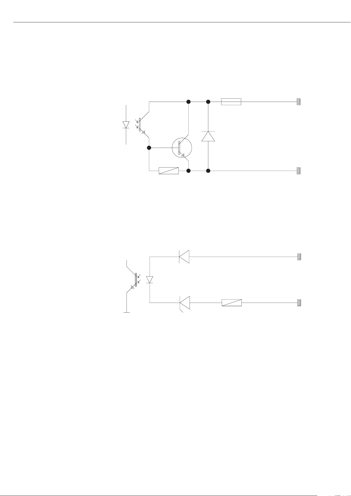
78
Ejemplo: diagrama de circuito básico
YDO01M-IO, opción A5:
especificaciones
Entradas digitales
– Número: 5
– Nivel bajo: –3 V hasta +5 V
– Nivel alto: +11 V hasta +30 V
– Toma de
corriente máx.: 2,6 mA bei 15 V
– Conexión de las entradas aplicando
la tensión correspondiente.
Salidas digitales
– Número: 5
– Flujo de corriente máximo
de cada canal: 100 mA
– Alcance tensión 0–30 Vdc
– Cada salida se forma por
un optoacoplador.
YDO01M-EN (Opción B9)
Suministro
– Módulo de interfaz YDO01M-EN
– Instrucciones de funcionamiento
(este documento)
– Descripción de la interfaz
(bus de campo para Modbus TCP
(fieldbus = “Bus de campo”)
Montaje
El módulo de interfaz YDO01M-EN
(interfaz Ethernet) se conecta directa-
mente, sin configuración, con la tarjeta
de circuitos impresos digital de la
báscula. Ver al respecto el capítulo
“Montaje en el visor”.
Enchufar conector del cable Ethernet
Sartorius YCC02-RJ45M7 (Opción M38)
en la hembrilla del módulo de interfaz.
Advertencia:
!Utilizar solamente cable y conector
según la especificación Ethernet (CAT5
o superior):
Cable Ethernet con atornilladura
de cable Sartorius N° de pedido
YCC02RJ45M7 (opción M38)
Módulo de interfaz utilizable sólo en
los siguientes aparatos:
– Visores MIS1, MIS2 (IP65)
– Básculas completas MW1, MW2 (IP65)
1
23
4
1
0.2A
4
30V
OUTx_high
OUTx_low
Inputx_high
LV1
LV1
LV2
23
Inputx_low
LV2

79
Diagrama de asignación de terminales
COM1
– Interfaz RS232: YDO01M-232 (opción
A11), YDO01M-232CLK (A31):
Asignación de pines de la regleta de
bornes de 8 pines en el módulo de
interfaz:
Pin 1: +12 V: Tensión de funciona-
miento para impresora Sartorius
Pin 2: Reset_Out
(Reinicio periferia)
Pin 3: +5 V Out
Pin 4: Masa (GND)
Pin 5: Clear to Send (CTS)
Pin 6: Data Terminal Ready (DTR)
Pin 7: Entrada de datos (R+D)
Pin 8: Salida de datos (T+D)
UniCOM
– Asignación de pines de dos regletas de
bornes de 10 pines en el módulo de
interfaz:
Interfaz RS232: YDO01M-232CO
(opción A1):
Pin 1: Clear to Send (CTS)
Pin 2: Data Terminal Ready (DTR)
Pin 3: Entrada de datos (R+D)
Pin 4: Salida de datos (T+D)
Pin 5: Masa (GND)
Pin 6: In Universal
Pin 7: Salida de control »menor«
Pin 8: Salida de control »igual«
Pin 9: Salida de control »mayor«
Pin 10: Salida de control »set«
Pin 11: +12 V: Tensión de funciona-
miento para impresora Sartorius
Pin 12: Reset_Out
(Reinicio periferia)
Pin 13: Masa (GND)
Pin 14: Masa (GND)
Pin 15: Salida + 5 V
Pin 16: +5 V conectada
(p. ej. para lector de código de
barras)
Pin 17: Masa (GND)
Pin 18: Masa (GND)
Pin 19: no asignado
Pin 20: Salida tensión alimentación
externa +15 ... 25 V
Interfaz IO digital:
YDO01M-IO (opción A5):
Pin 1: Puerto de salida ext. 5: bajo
Pin 2: Puerto de salida ext. 5: alto
Pin 3: Puerto de salida ext. 4: bajo
Pin 4: Puerto de salida ext. 4: alto
Pin 5: Puerto de salida ext. 3: bajo
Pin 6: Puerto de salida ext. 3: alto
Pin 7: Puerto de salida ext. 2: bajo
Pin 8: Puerto de salida ext. 2: alto
Pin 9: Puerto de salida ext. 1: bajo
Pin 10: Puerto de salida ext. 1: alto
Pin 11: Puerto de entrada 5: bajo
Pin 12: Puerto de entrada 5: alto
Pin 13: Puerto de entrada 4: bajo
Pin 14: Puerto de entrada 4: alto
Pin 15: Puerto de entrada 3: bajo
Pin 16: Puerto de entrada 3: alto
Pin 17: Puerto de entrada 2: bajo
Pin 18: Puerto de entrada 2: alto
Pin 19: Puerto de entrada 1: bajo
Pin 20: Puerto de entrada 1: alto
– Asignación de pines de las dos regletas
de bornes en el módulo de interfaz:
YDO01M-485: funcionamiento RS485
(opción A2):
Pin 1: Datos + (T+D-R+D+)
Pin 2: Datos - (T+D-R+D-)
Pin 3: no asignado
Pin 4: no asignado
Pin 5: Señal masa, galvánicamente
separada (GND_GALV)
Pin 6: Señal masa, galvánicamente
separada (GND_GALV)
Pin 11: Entrada de tensión vers. ext.
+15 ... 25 V *
Pin 12: Entrada de tensión vers. ext.
+15 ... 25 V *
Pin 13: Masa (GND) *
Pin 14: Masa (GND) *
1
2
3
4
5
66
YDO01M-485: funcionamiento RS422
(opción A3):
Pin 1: Salida de datos + (T+D+)
Pin 2: Salida de datos - (T+D-)
Pin 3: Entrada de datos + (R+D+)
Pin 4: Entrada de datos - (R+D-)
Pin 5: Señal masa, galvánicamente
separada (GND_GALV)
Pin 6: Señal masa, galvánicamente
separada (GND_GALV)
Pin 11: Entrada de tensión vers. ext.
+15 ... 25 V *
Pin 12: Entrada de tensión vers. ext.
+15 ... 25 V *
Pin 13: Masa (GND) *
Pin 14: Masa (GND) *
* = no separado galvánicamente
YDA01M-20MA (interfaz
corriente/tensión):
Regleta de bornes de 6 pines en el
módulo de interfaz
Pin 1: I_out (+)
para interfaz de corriente
(0/4 hasta 20/24 mA)
Pin 2: I_in (–)
para interfaz de corriente
(0/4 hasta 20/24 mA)
Pin 3: V_out (+)
para interfaz de tensión,
0 hasta 10 V
Pin 4: V_in (–)
para interfaz de tensión,
0 hasta 10 V
Pin 5: GND, galvánicamente separada
(masa separada galvánicamente)
Pin 6: GND, galvánicamente separada
(masa separada galvánicamente)
Asignación de pines para
interfaz - Ethernet (RJ45)
YDO01M-EN (opción B9):
Pin 1: TxD+
Pin 2: TxDPin 3: RxD+
Pin 4: no asignado
Pin 5: no asignado
Pin 6: RxDPin 7: no asignado
Pin 8: no asignado
Chassis: GND
1
2
3
4
5
66
1
2
3
4
5
66

80
Ajustes previos COM1 y UniCOM
Sinopsis menú operativo de las interfaces »COM1« y »UniCOM«
(al respecto ver también la sinopsis de menú operativo en el capítulo »Ajustes previos« de las Instrucciones de funcionamiento de Midrics)
Appl
Fn-Key
Setup WP-1
COM1 OFF *
DATPROT SBI *
(Protocolo XBPI-232
de datos) SMA
Impresora YDP01IS Line (Cinta) *
Label (Etiqueta)
Label (Etiqueta), Form-Feed man.
YDP02
YDP03
YDP02IS Line (Cinta) *
Label (Etiqueta)
UNI-PRI (impresora universal)
YDP04IS Line (Cinta) *
Label (Etiqueta)
Label (Etiqueta), Form-Feed man.
MEMORIA YAM01IS (Memoria Alibi)
UniCOM OFF *
DATPROT SBI *
(Protocolo XBPI-232
de datos) XBPI-485
SMA
ETHERNET Source IP: 192.168.0.1 *
Source name
Listen port: 49155 *
Subnet mask: 255.255.255.0 *
Gateway IP: 0.0.0.0 *
DNS IP: 0.0.0.0 *
Target IP: 0.0.0.0 *
Target port: 49155 *
Protocol TCP *
UDP
Mode SBI-SRV * 6.1. Salida de datos manual/automática
(servidor) 6.1.1 Manual sin estabilidad
6.1.2 * Manual después de estabilidad
6.1.4 Automática sin estabilidad
6.1.5 Automática con estabilidad
6.1.7 Impresión protocolo para
ordenador (PC)
7.2. Salida de datos: formato de línea
7.2.1 Para datos brutos: 16 caracteres
7.2.2 * Para otras aplicaciones:
22 caracteres
SBI-C/S 6.1. Salida de datos manual/automática
(cliente) 6.1.1 Manual sin estabilidad
6.1.2 * Manual después de estabilidad
6.1.4 Automática sin estabilidad
6.1.5 Automática con estabilidad
6.1.7 Impresión protocolo para
ordenador (PC)
6.3. Salida de datos autom.
dependiente de tiempo
6.3.1 * 1 ciclo de lectura
6.3.2 2 ciclos de lectura
6.3.4 10 ciclos de lectura
6.3.7 100 ciclos de lectura
7.2. Salida de datos: formato de línea
7.2.1 Para datos brutos: 16 caracteres
7.2.2 * Para otras aplicaciones:
22 caracteres
xBPI
SMA
Modbus/TCP

81
Setup UniCOM Impresora YDP01IS Line (Cinta) *
Label (Etiqueta)
Label (Etiqueta), Form-Feed man
YDP02
YDP03
YDP02IS Line (Cinta) *
Label (Etiqueta)
UNI-PRI (impresora universal)
YDP04IS Line (Cinta) *
Label (Etiqueta)
Label (Etiqueta), Form-Feed man
MEMORY YAM01IS (memoria Alibi)
ANALÓGICA (interfaz analógica)
CTRL IO: CTR INP: 8. 4. x TTL; per YDO01M-232CO, para YDO01M-232CO, opción A1
entradas/ entradas 8. 17. x separada galvánicamente; para
salidas de de control Fino a YDO01M-IO, opción A5
control 8 . 21. x
CTR OUT 8. 24. x separada galvánicamente; para
(salidas hasta YDO01M-IO, opción A5
de control) 8. 28. x
* = ajuste previo de fábrica

Interfaz Ethernet
En el menú “UNICOM” vía “ETHERNET”
realizar las entradas numéricas bajo IP
Source, Puerto listas, etc. En Nombre
Source pueden utilizarse letras y cifras.
Pueden entrarse hasta un máximo de
15 caracteres de entrada. El SourceName (nombre de origen) puede
entrarse como alternativa a Source-IP
(IP de origen).
Números de puerto
Rango de validez: 0 – 65535
Dado que muchos de los puertos,
hasta 49150 ya han sido asignados,
recomendamos emplear números de
puerto por sobre 49150. No es válido
para ModBus/TCP, ya que aquí es válido
el número de puerto: 502 (ver folleto:
Fieldbus (bus de campo)).
82
Configurar interfaces
Ajustar la interfaz de datos universal
UniCOM en el menú operativo del visor
para el estado de funcionamiento previsto (conexión de un aparato periférico). El fragmento correspondiente del
árbol de menú está representado en la
ilustración a la izquierda.
Explicaciones adicionales al respecto se
encuentran en el capítulo »Ajustes previos« de las Instrucciones de funcionamiento de Midrics.
Interfaces RS485 / RS422
Si está configurada la tarjeta de circuitos impresos para el funcionamiento de
RS422, entonces pueden utilizarse los
ajustes »SBI«, »XBPI-232« y SMA en el
menú.
Interfaz analógica YDA01M-20MA
Configurable en el menú:
– Valor salida (ítem del menú 8-12):
8-12-1: Valor neto
(ajuste previo de fábrica)
8-12-2: Valor bruto
– Representación del error
(ítem del menú 8-13):
8-13-1: Nivel alto (20 mA)
(ajuste previo de fábrica)
8-13-2: Nivel bajo (0/4 mA):
durante el funcionamiento la
tensión de esta interfaz es
de 5 V
– Modo salida (ítem del menú 8-14):
8-14-1: Cero hasta carga máxima
(ajuste previo de fábrica)
8-14-2: Valores mín./máx.
– Salida valores mín./máx.
(ítem del menú 8-15):
8-15-1: Entrada mín. (0/4 mA) en kg
8-15-2: Entrada máx. (20 mA) en kg
Sobre la selección: pueden seleccionarse
libremente los valores mín./máx. del
rango de pesada para la salida de 0/4
hasta 20 mA (0–10 V). Esta selección es
válida también para una báscula SBI,
pero sólo para el valor neto.
La entrada de los valores mín./máx. se
realiza siempre en la unidad “kilogramo”. Es posible la entrada de valores de
peso negativos. También el valor mín.
puede ser mayor que valor máx. si se
desea tener una salida de corriente en
disminución (descendente).
Ejemplos:
Curva de corriente ascendente
Valor neto mín.: -1 kg
Valor neto máx.: 4 kg
Curva de corriente descendente para
báscula XBPI
Valor mín.: 5 kg
Valor máx.: 1 kg
Curva de corriente descendente para
báscula SBI
Valor mín.: 5 kg
Valor máx.: 1 kg

83
Interfaz Ethernet: Inicialización
Lectura: fin de inicialización
Si la inicialización del módulo Ethernet
ha finalizado exitosamente, aparece el
símbolo “ ”.
Módulo
de red inicializa
Si la inicialización no ha sido exitosa,
no aparece ningún símbolo. ¡El símbolo
no expresa nada con respecto a un
estado de conexión en modo red!
Conexiones TCP:
En el modo funcionamiento SBI-C/S,
Midrics separa la conexión siempre
automáticamente después de un
segundo.
En los otros modos de funcionamiento:
SBI-SRV, SMA, XBPI, ModBus/TCP la
conexión se mantiene hasta que el PC
(Cliente) se separe. Puede realizarse sólo
una conexión a un mismo tiempo.
Interfaz Ethernet: Características
IP Source: Dirección IP del visor Midrics
Si se selecciona la Dirección 0.0.0.0, ha de asignarse dinámicamente una
Dirección IP a través de un Servidor DHCP existente en red. Entonces
debe ya haber algo registrado en Source Name (nombre de origen).
Nombre Source: Este parámetro es alternativo a Source-IP (IP de origen). Puede entrarse
un nombre, con 15 caracteres, para la designación de Midrics. ¡Entonces
debe estar ajustada la dirección 0.0.0.0 bajo Source-IP (IP de origen)!
El nombre se da a conocer al Domain-Name-Server (DNS), si
– bajo IP DNS se ha entrado una Dirección IP,
o bien
– si se ha asignado una Dirección IP a través de DHCP.
Puerto aparato: Número de puerto en el que se vincula Midrics para el funcionamiento del
Servidor.
Máscara Subnet: Máscara Dirección IP para activar Direcciones IP en una red secundaria.
Si la máscara ha de asignarse a través de un Servidor DHCP, tiene que
entrarse 0.0.0.0.
IP Gateway: Dirección IP de un Gateway
A través de IP destino, contactar con un Servidor deseado, que se encuen-
tra en otra red. Si la Dirección IP se asigna dinámicamente a través de un
Servidor DHCP, tiene que entrarse 0.0.0.0.
IP dest.: Dirección del Servidor, que ha de recibir los datos de Midrics.
Importante para el funcionamiento del Cliente de Midrics, si se ha selec-
cionado Modo SBI con salida de datos “automática”. Al usarse UDP,
hay que utilizar aquí una Dirección IP.
Puerto dest.: Número de puerto en el que se vincula un Servidor con “IP dest.”,
para recibir datos de Midrics.
Protocolo: Seleccionar Protocolo Transporte, con el que han de enviarse datos vía
Ethernet.
Seleccionar entre:
- TCP, orientado a la conexión con más alta fiabilidad de datos,
o bien
- UDP, no conectado (para Modbus/TCP, sin efecto)
Modo: Seleccionar formato de datos, que contiene datos útiles, que se intercalan
en TCP o UDP (p. ej. SMA es vinculado con TCP o UDP vía Ethernet).
En los protocolos SBI-SRV, XBPI y SMA, Midrics ha de considerarse
siempre como Servidor. En SBI-C/S, Midrics es al mismo tiempo Servidor
y Cliente. Modo Cliente existe, si la tecla p [Print] es activada, o bien
si el parámetro “Salida de datos” ha sido ajustado en “Automática”.
Para el modo OPC, ajustar el modo “Servidor SBI”. Para los otros casos,
Midrics es un Servidor. En ModBus/TCP, Midrics está siempre activo como
Servidor (ver también en el Folleto Fieldbus (bus de campo)).
Comportamiento
de conexión: Con módulo de interfaz activado, la lectura del valor de peso puede
aparecer con un retardo de hasta 20 segundos.

84
Sincronización
Para la transmisión de datos entre el
ordenador y el visor se transmiten telegramas de caracteres ASCII vía la interfaz de datos. Para la transmisión de
datos libre de errores deben coincidir
los parámetros para la velocidad de
baudios, la paridad y Handshake y el
formato de caracteres.
Una adaptación del visor se efectúa por
medio de los ajustes correspondientes
en el Setup (Menú). Adicionalmente a
estos ajustes, la salida de datos del visor
puede hacerse dependiente de diferentes condiciones. Estas condiciones están
descritas con los programas de aplicación correspondientes.
Una interfaz de datos abierta (ningún
aparato periférico conectado) no origina
ningún mensaje de error.
Handshake
La interfaz de datos de la báscula está
equipada con un amortiguador de emisión y recepción. En el Setup del visor
pueden ajustarse los diferentes tipos de
Handshake:
– Hardware-Handshake (CTS/DTR)
– Software-Handshake (XON, XOFF)
Hardware-Handshake
Con el Hardware-Handshake con la
interfaz de 4 cables puede enviarse aún
1 carácter después de CTS.
Software-Handshake
El Software-Handshake se controla por
medio de XON y XOFF. Al encender un
aparato debe enviarse un XON, para
liberar un aparato eventualmente
conectado.
El transcurso de la transmisión de datos
sucede de la siguiente manera:
Báscula ––– byte –––> Ordenador
(Emisor) ––– byte –––> (Receptor)
––– byte –––>
––– byte –––>
<–– XOFF –––
––– byte –––>
––– byte –––>
...
(Pause)
...
<–– XON –––
––– byte –––>
––– byte –––>
––– byte –––>
––– byte –––>
Emisor
Un XOFF recibido evita envíos posteriores de caracteres. Un XON recibido libera nuevamente el envío.
Receptor
Para no cargar demasiado el envío con
caracteres de control, se realiza la liberación recién por el XON, después que el
amortiguador está casi vacío.

85
Interfaz de datos
Configurar la interfaz
de datos como interfaz
de comunicación (datprot)
En el menú Setup, bajo COM1 o UniCOM, «Protocolo de datos» (datprot) se
configura la interfaz como interfaz de
comunicación.
Comunicación SBI
Se trata de una interfaz ASCII simple.
Bajo el ítem de menú 6-1 y 6-3 se ajusta,
cómo han de salir los datos:
– Salida manual de un valor de lectura con
o sin estabilidad (ítem de menú 6-1-1 y
6-1-2)
– Salida automática de un valor de lectura
con o sin estabilidad (ítem de menú 6-14 y 6-1-5) en dependencia de un número
de ciclos de lectura. Bajo el ítem de menú
6-3 se ajusta la cantidad de intervalos de
lectura para la salida.
– Salida de un protocolo de impresión con-
figurable. La salida está vinculada al ítem
de menú «Protocolo de impresión» (prt-
prot).
Con excepción de la salida de un protocolo de impresión configurable se imprime el valor de lectura actual (valor de
pesada con unidad, valor calculado, lectura numérica y alfabética).
Comunicación SMA
Protocolo de comunicación estandarizado de Scale Manufacturers Association
Formato de entrada de datos
(Comandos)
Un ordenador conectado a través de la
interfaz de datos (comunicación SBI)
puede enviar comandos hacia el visor
para controlar funciones, funciones de
báscula o de aplicación.
Todos los comandos tienen un formato
marco común (formato de entrada de
datos). Comienzan con el carácter ESC
(ASCII: 27) y finalizan con la secuencia
de caracteres CR (ASCII: 13) y LF (ASCII:
10). Su largo varía de 4 caracteres mínimo (1 carácter comando) hasta 7 caracteres máximo (4 caracteres comando).
Los comandos representados en la tabla
siguiente tienen que ser complementados con el formato marco respectivo
ESC ... CR LF.
Ejemplo: ha de enviarse el comando de
salida »P« (“envía valor de lectura”) al
visor. Para esto se envía la secuencia de
caracteres »ESC P CR LF«.
Comando Significado
K Modo de pesada 1
L Modo de pesada 2
M Modo de pesada 3
N Modo de pesada 4
O Bloquear teclado
P Envía valor de lectura hacia
la interfaz de datos
R Liberar teclado
T Tarar y poner en cero
(función combi tara)
f3_ Poner a cero (Zero),
como comando »kZE_«
f4_ Tarar (sin puesta a cero),
como comando »kT_«
kF1_ F1: Activar tecla k
kF2_ F2: Activar tecla c
(sólo con modelo Midrics 2)
kF3_ F3: Activar tecla r
(sólo con modelo Midrics 2)
kF4_ F4: Activar tecla O
(sólo con modelo Midrics 2)
kF5_ F5: Activar tecla w
(sólo con modelo Midrics 2)
Comando Significado
kF6_ F6: Activar tecla I
(sólo con modelo Midrics 2)
KF7_ Tecla d
kCF_ CF: Activar tecla c
(sólo con modelo Midrics 2)
kP_ Activar tecla p
Imprimir sobre interfaz de
impresión
kT_ Activar tecla )
(tarar)
kZE_ Activar tecla (
(puesta a cero)
x1_ Salida modelo
plataforma de pesaje
actual,
ejemplo: »LP6200S-0C«
x2_ Salida número de serie
plataforma de pesaje
actual,
ejemplo: »0012345678 «
x3_ Salida versión Software
plataforma de pesaje
actual,
ejemplo: »00-20-04«
z1_ Entrada: línea de encabe-
zado de protocolo 1
z2_ Entrada: línea de encabe-
zado de protocolo 2
txx...x_ xx...x: entrada letras
Largo de acuerdo a la
entrada (sólo con modelo
Midrics 2)
El carácter »_« (Underline) es el carácter
ASCII 95 decimal.
Formato para la entrada de las líneas de
encabezado de protocolo: »ESC z x a ...
a _ CR LF« con x=1 o 2 y a ... a: 1 hasta
20 caracteres para la línea de encabezado x, seguido de los caracteres Underline, CR y LF.

86
Formato salida de datos
Una línea impresa consta de 22 caracteres, máximo (20
caracteres de impresión más dos caracteres de control). Los
primeros 6 caracteres, del así llamado Header (identificación),
identifican el valor subsiguiente.
La identificación puede desconectarse bajo el ítem de menú 7-2,
de manera que la línea impresa consta de 16 caracteres (14
caracteres imprimibles más dos caracteres de control).
Ejemplo:
+ 235 pcs sin identificación (Header)
Qnt + 235 pcs con identificación (Header)
Caracteres que no aparecen en la lectura, se imprimen como
caracteres en blanco. En cifras sin punto decimal no se imprime
punto decimal.
Formato de salida con 16 caracteres (sin identificación)
Funcionamiento normal:
Pos. 123456789101112131415 16
+* AAAAAAAA* E E E CR LF
o - * AAAAAAAA* E E E CR LF
o **************CR LF
+-: signo
*: espacio en blanco
A: caracteres de lectura (máx. 7 cifras y punto decimal)
E: caracteres para la unidad de medición (1 hasta 3 letras,
seguido de 2 hasta 0 caracteres en blanco)
CR: Carriage Return
LF: Line Feed
Funcionamiento especial:
Pos. 12345678910111213141516
******––******CR LF
o bien ******H*******CR LF
o bien ******HH******CR LF
o bien ******L*******CR LF
o bien ******LL******CR LF
o bien ******C*******CR LF
*: espacio en blanco
– –: de la báscula
H: desborde de peso
HH: desborde de peso en control báscula
L: peso muy liviano
LL: peso muy liviano en control báscula
C: calibración
Mensaje de error:
Pos. 12345678910111213141516
***Err**##****CRLF
o bien ***Err*###****CRLF
*: espacio en blanco
#: cifra (número de error de 2 ó 3 posiciones)
Ejemplo (Salida del valor de pesada +1255,7 g):
Pos. 12345678910111213141516
+** * 1255. 7* g* * CRLF
Posición 1: signo +, - o espacio vacío
Posición 2: espacio vacío
Posición 3-10: valor de peso con punto decimal. Ceros inicia-
les se imprimen como espacios en blanco.
Posición 11: espacio vacío
Posición 12-14: caracteres para unidad de medida o espacio en
blanco
Posición 15: Carriage Return
Posición 16: Line Feed
Formato de salida con 22 caracteres
(con identificación (Header))
Funcionamiento normal:
Pos. 12345678910111213141516171819202122
KKKKKK+* AAAAAAAA* E E E CRLF
o bien
KKKKKK- * AAAAAAAA* E E E CRLF
o bien
********************CRLF
K: carácter para identificación, a la derecha provisto de carac-
teres en blanco
+-: signos
*: espacio en blanco
A: caracteres de lectura (máx. 7 cifras y punto decimal)
E: caracteres para la unidad de medición (1 hasta 3 letras,
seguido de 2 hasta 0 caracteres en blanco)
CR: Carriage Return
LF: Line Feed
Funcionamiento especial:
Pos. 12345678910111213141516171819202122
Stat********––******CRLF
o bien
Stat********H*******CRLF
o bien
Stat********HH******CRLF
o bien
Stat********L*******CRLF
o bien
Stat********LL******CRLF
o bien
Stat********C*******CRLF
*: espacio en blanco – –: de la báscula
H: desborde de peso HH: desborde de peso en control báscula
L: peso muy liviano LL: peso muy liviano en control báscula
C: calibración

87
87
Interfaces de datos
Protocolo GMP
Con el ítem de menú activo, en el protocolo de impresión, además del resultado de medición aparece un encabezado GMP y un pie de página GMP (GMP:
Good Manufacturing Practice).
El encabezado GMP se imprime antes
del primer resultado de medición.
El pie de página GMP se imprime,
o bien, después de cada resultado de
medición (protocolo GMP siempre para
1 resultado de medición, 7-11-2) o,
después del último resultado de medición de una serie de resultados de
medición (protocolo GMP siempre para
varios resultados de medición, 7-11-3).
Una serie de resultados de medición se
finaliza pulsando largo la tecla p.
En este caso, el símbolo A es visible en
la lectura después de la impresión del
encabezado GMP hasta la impresión
del pie de página GMP.
Al finalizar un proceso de calibración
se genera automáticamente siempre
una impresión GMP.
Con las impresiones conformes con
GMP en una impresora de etiquetas
bajo el ajuste de menú 7-11-3 se deshace la relación entre el encabezado
GMP y el pie de página GMP (impresión
en diferentes etiquetas). Por lo tanto,
las impresiones GMP en la impresora de
etiquetas deberán realizarse razonablemente sólo bajo el ajuste de menú
7-11-2.
A continuación, se presentan un ejemplo de un encabezado de protocolo GMP
y un ejemplo de un pie de página GMP:
------------------- línea de rayas
14.01.2007 09:43 fecha/hora
1
)
Modelo MIS2 modelo Midrics
No. ser. 12345678 N°. de serie Midrics
Vers. 1.1007.12.1 vers. softw. aplicación
BVers. 01-25-01 vers. softw. sw. de base
------------------- línea de rayas
Pie de página GMP:
------------------- línea de rayas
14.01.2007 09:45 fecha/hora
1)
Nombre: espacio para firma
línea en blanco
------------------- línea de rayas
1
) YDO01M-232, opción A31 necesaria

Sartorius AG
Weender Landstrasse 94–108
37075 Goettingen, Germany
Phone +49.551.308.0
Fax +49.551.308.3289
www.sartorius-mechatronics.com
Copyright by Sartorius AG,
Goettingen, Germany.
All rights reserved. No part of
this publication may be reprinted
or translated in any form or by any
means without the prior written
permission of Sartorius AG.
The status of the information,
specifications and illustrations in
this manual is indicated by the
date given below.
Sartorius AG reserves the right to make
changes to the technology, features,
specifications and design of the
equipment without notice.
Status:
September 2007, Sartorius AG,
Goettingen, Germany
Printed in Germany on paper that has been bleached
without any use of chlorine
W1A000 · KT
Publication No.: WYD6131-p07093
 Loading...