


Series 9
Setup Manual

Safety Notice ....................................................................................................... |
1 |
Specifications ...................................................................................................... |
2 |
Series 9 (Basic Group 'A' Keys) Front Panel .................................................... |
3 |
Series 9 (Optional Group 'B' Keys) Front Panel ............................................... |
3 |
Status Indicators ................................................................................................. |
4 |
Key Functions (Group ‘A’) ................................................................................. |
5 |
Optional Key Functions (Group ‘B’) .................................................................. |
6 |
Operating Instructions........................................................................................ |
7 |
Configuration Mode Key Functions................................................................... |
9 |
Setup/Configuration Mode Access .................................................................. |
10 |
Configuration/Calibration Mode....................................................................... |
10 |
Configuration/Calibration Menu Choices ........................................................ |
11 |
Calibration Audit Trail....................................................................................... |
17 |
Input/Output Connections ................................................................................ |
18 |
Jumpers, Headers and Terminal Blocks Location ......................................... |
20 |
Error Messages ................................................................................................. |
21 |
Jumper Settings ................................................................................................ |
21 |
Customizing the Print Format .......................................................................... |
22 |
Print Output Formats & Printout Samples ...................................................... |
25 |
Setup Record ..................................................................................................... |
30 |
Display Character Reference ........................................................................... |
31 |
ASCII Character Set .......................................................................................... |
32 |
Password ........................................................................................................... |
33 |
FlexWeigh
3158 Condo Court, Santa Rosa
California 95403 USA
Tel: 800 -650-8823, 707 -545-0623
Fax: 707 -575-1356
COPYRIGHT NOTICE
This Setup Manual is copyrighted. No guarantee is given as to the correctness of its contents. FlexWeigh reserves the right to make changes without notice.

Safety Notice
It is important that FlexWeigh’s equipment is installed and operated in such a way that all applicable safety requirements are met. It is your responsibility as a user to ensure that you identify the relevant standards and comply with them. Failure to do so may result in damages to equipment and personal injury. In particular, you should review the contents of the Setup Manual carefully before installing or operating the equipment.
This equipment is not designed for placement in hazardous or explosive environments that require Factory Mutual Approval.
Under no circumstances will the supplier of the equipment be liable for any incidental, consequential, or special damages of any kind whatsoever, including but not limited to lost profits arising from or in any way associated with the use of the equipment or this Setup Manual.
If you find anything in this guide to be inaccurate, misleading, or lacking please FAX your comments and suggestions to:
Document Control at FlexWeigh
Fax: 707-575-1356
1

|
Specifications |
|
|
Internal Resolution |
1,000,000 counts at 3mV/V |
Display Resolution |
Selectable (1/10,000 NTEP approval pending) |
Input Sensitivity |
1μV/graduation typical, 0.4μV/graduation minimum |
Display Increments |
Selectable x1, x2, x5, x10, x20, x50, x100 |
Decimal Point |
Selectable 0 ~ 4 |
Display |
7 Digits 7-Segment LED display, 14.2mm (0.56”) high, with |
|
annunciators (7 LED lamps) for function select, Stable, Center Zero, |
|
Net, Print, kg, lb, and L ow Battery display |
Keyboard |
Standard - 6 button tactile keypad including Power On/Off key |
|
Optional - 18 button tactile keypad including Power On/Off key |
Audio Alarm |
Tone for key entry confirmation and low battery alarm |
A/D Conversion Rate |
7.5 updates per second |
Load Cell Excitation |
9.7VDC or 5VDC selectable. Drive up to six 350 ohm load cells |
Voltage |
|
Analog Input Range |
0.2mV/V to 3.0mV/V maximum |
Non-Linearity |
0.01% of full scale or less |
Over Capacity |
Display “CAP OL” when exceeds full scale capacity |
Tare |
Standard - Pushbutton tare |
|
Optional - Pushbutton tare, numeric tare entry & 10 predefined tare |
|
recall |
Auto Zero Tracking |
Selectable to 3.0 d by 0.5 d step |
Motion Window |
Key in data 0..255 (1 = 0.5 d) |
Calibration Method |
Software – Menu driven prompting |
Units of Measure |
Selectable kg/lb/g/oz, up to 2 units displayable |
RFI/EMI Protection |
All signal and excitation lines filtered to –65db min. @ 500MHz |
Filtering |
Selectable digital filter |
RS-232C data output |
COM Port 1. Full Duplex or Bi-directional |
|
COM Port 2. Simplex or Unidi rectional (output only) |
|
Selectable baud rates (1200,2400,4800,9600,19200), manual or auto |
|
print, continuous data out or bi -directional communication |
Remote Display |
Standard – Remote only |
|
Optional - Programmable as Main Indicator or Remote Display |
Custom Print Format |
Programmable, up to 119 characters for Custom Print Format and up |
|
to 23 characters for Continuous Print Format |
Set Points |
Standard - None |
|
Optional - Selectable up to 2 Set Points for Low and High limit settings |
Power |
100/115VAC or 220/230VAC, 50-60Hz, 6VA with built-in Charger for |
|
12VDC 2-2.3AH Rechargeable Sealed Lead Acid Battery |
|
(Battery Dimension 67 (H) x 178 (W) x 34 (D) mm, is optional) |
Current Consumption |
100mA + 30mA per 350 ohm lo ad cell |
Operating Temp |
-10 degrees C to + 40 degrees C |
Relative Humidity |
Maximum 90% RH, Non-condensing |
Dimensions |
150 (6”)H x 230 (9.1”)W x 1 00 (4”)D mm - ABS (Standard) |
|
140 (5.5”)H x 230 (9.1”)W x 90 (3.5”)D mm - Stainless Steel (Optional) |
Shipping Weight |
2.7lb (5.1lb with optional b attery) – ABS (Standard) |
|
4.7lb (7.1lb with optional b attery) – Stainless Steel (Optional) |
Enclosure |
ABS plastic Casing, Optional Stainl ess Steel, NEMA 4-X |
Warranty |
One Year Limited Warranty |
2

Series 9 (Group ‘A’ Keys) Front Panel
Group ‘A’ Keys |
Group ‘B’ Keys |
|
|
3
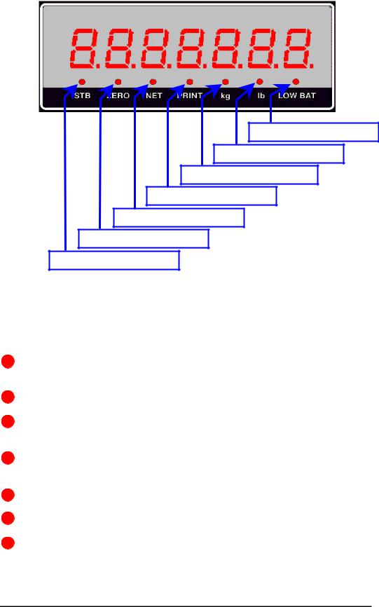
Status Indicators
Low Battery Indicator
Pound Unit Indicator
Kilogram Unit Indicator
Print Status Indicator
Net Mode Indicator
Zero Status Indicator
Stable Status Indicator
There are 7 LED indicators just below the 7-segment weight display with the following functions.
STB – (Stable Indicator) Indicates there is no weight motion on the weighing platform.
ZERO- (Center Zero Indicator) Indicates the weight is at center of zero.
NET-(Net Weight Indicator) Indicates the currently displayed weight is a net weight (a tare value is active).
PRINT-(Print Indicator) Flashes to indicate a successful print transmission.
Kg-(Kilogram Indicator) Indicates the current weight unit is kilograms.
Lb-(Pounds) Indicates the current weight unit is pounds.
LOW BAT-(Low Battery) Indicates the battery is low during battery operation. In the setup mode, the blinking of this LED is an indication to enter a numeric value.
4

Key Functions Group ‘A’
ON / OFF – Power switch used to switch on and off the Series 9 meter.
ZERO – Zero button used to zero the indicator when the weight display is stable.
TARE – Tares the indicator when the weight display is stable.
PRINT – Initiates a print transmission when the weight is stable.
G/N - Toggles the displayed weight between net and gross.
Select / Enter – Toggles between the selected units of measure.
5

Optional Key Functions Group ‘B’
‘0’ / F10 - Enters ‘0’, space, Double Quotation Mark or Back Slash depending upon the current mode of operation.
‘1’ / F1 – Enters ‘1’ dash, period, forward slash, right and left parenthesis. This key also represents Tare Register No. 1.
‘2’/ F2 - Enters ‘2’, ’A’, ’B’ or ’C’ depending upon the current mode of operation. This key also represents Tare Register No. 2.
‘3‘/ F3 – Enters ‘3’, ‘D’, ‘E’ or ‘F’ depending upon the current mode of operation. This key also represents Tare Register No. 3
‘4’ / F4 - Enters ‘4’, ‘G’, ‘H’ or ‘I’ depending upon the current mode of operation. This key also represents Tare Register No. 4.
‘5’ / F5 - Enters ‘5’, ‘J’, ‘K’ or ‘L’ depending upon the current mode of operation. This key also represents Tare Register No. 5.
‘6’ / F6 – Enters ‘6’, ‘M’, ‘N’ or ‘O’ depending upon the current mode of operation. This key also represents Tare Register No. 6.
"7’ / F7 - Enters ‘7’, ‘P’, ‘Q’, ‘R’ or ‘S’ depending upon the current mode of operation. This key also represents Tare Register No. 7.
‘8’ / F8 - Enters ‘8’, ‘T’, ‘U’ or ‘V’ depending upon the current mode of operation. This key also represents Tare Register No. 8.
‘9’ / F9 – Enters ‘9’, ‘W’, ‘X’, ‘Y’ or ‘Z’ depending upon the current mode of operation. This key also represents Tare Register No. 9
Clear – Clear entry or backspace depending upon the current mode of operation.
Shift - Selects function keys or toggles alpha or numeric entry depending on the current mode of operation.
6

Operating Instructions
qPower ON Zeroing
Upon applying power the instrument will:
i)If the applied load is less than or equal to 2% of the calibration zero point the instrument will establish zero and clear any tare values.
ii)If the applied load is greater than 2% of the calibration zero point the instrument will display “- - - - - - -“. The load may be removed to allow for automatic zeroing (above) or a manual zero may be established by pressing the ‘Zero’ button. Note: If the instrument has been configured to not allow for zeroing greater than 2% removing the load will be necessary.
qZeroing
To zero the scale press the [Zero] button.
i)2 % Zeroing
(1)This mode will allow pushbutton zero up to 2% of full scale capacity. The available scale capacity will not be affected by the zeroed amount.
ii)100 % Zeroing
(1)This mode will allow pushbutton zero up to 100% of full sc ale capacity. The available scale capacity will be reduced by the zeroed amount.
qPushbutton Tare (If enabled)
Place the object to tare on the scale and press the [Tare] button. The weight will be established as tare and the weight mode will switch to net.
qTare by Numeric Key (Optional Series 9, if enabled)
Key in the tare value using the numeric keys then press [Tare]. In sealed applications this function is only permitted when the gross weight is at zero.
7

qProgramming Recall Tare Values (Optional Series 9, if enabled)
(1)The optional Series 9 can maintain up to 10 predefined Tare values.
(2)To program a tare value press [Shift] and then [8]. The display
will prompt [T 0-END] and then [t no. 1]
(3)Key in the desired tare register number (1-10) and press [Enter].
(4)The display will prompt [T XXX.XX]
(5)Enter the desired tare value.
(6)To Exit programming tare registers, enter ‘0’ at the tare register
prompt.
qRecalling a Tare Value (Optional Series 9, if enabled)
Enter the desired tare register (1-10) then press the [Select/Enter] key. In sealed applications this function is only available when the gross weight is at zero.
qPreset Output Settings (Optional Series 9, if enabled)
. |
Press [SHIFT] then press [ 9 ], |
|
The display will prompt [S XXX.XX]. Key in the Start value for |
|
Set point 1 and press [Enter], |
|
The display will prompt [E XXX.XX]. Key in the End value for |
|
Set point 1 and press [Enter] |
|
Repeat the above sequence for Set point 2. |
8
Configuration Mode Key Functions
Zero - Terminates the setup mode or exits numeric entry without changing the last value
Tare - Not in use.
Print – Scroll forward through setup choices or increase the ava ilable parameter value.
G/N – Scroll backward through setup choices or decrease the available parameter value.
Select/Enter - Accept the current value or choice. Pressing quickly this key will advance next setup sub-menu. Use at the “END” prompt to save and exit setup.
The Optional Series 9 allow numeric data to be entered via the Group B keys.
9
 Loading...