Rice Lake IQ plus 355 User Manual

IQ plus® 355 Digital Weight Indicator
Panel Mount Option
PN 52948
Use the following procedure to install the panel mount option:
NOTE: The IQ plus 355 panel mount bezel gasket meets NEMA 12 requirements for dust-proof installations.
1.Use the cutout template to make a 9.8" W x 6.3" H (249 mm W x 160 mm H) cutout in the panel. Ensure cutout is far enough
f r o m p a n e l e d g e t o accommodate bezel: panel mount bezel dimensions are 10.5" W x 7.0" H (267 mm W x 178 mm H).
2.If attached, remove the tilt stand from the indicator enclosure.
3.Peel adhesive backing from the bezel gaskets, then press bezel into the panel cutout.
4.Insert the indicator into the panel mount bezel from the rear. Align
h o l e s i n s i d e o f i n d i c a t o r enclosure with holes in the bezel flange.
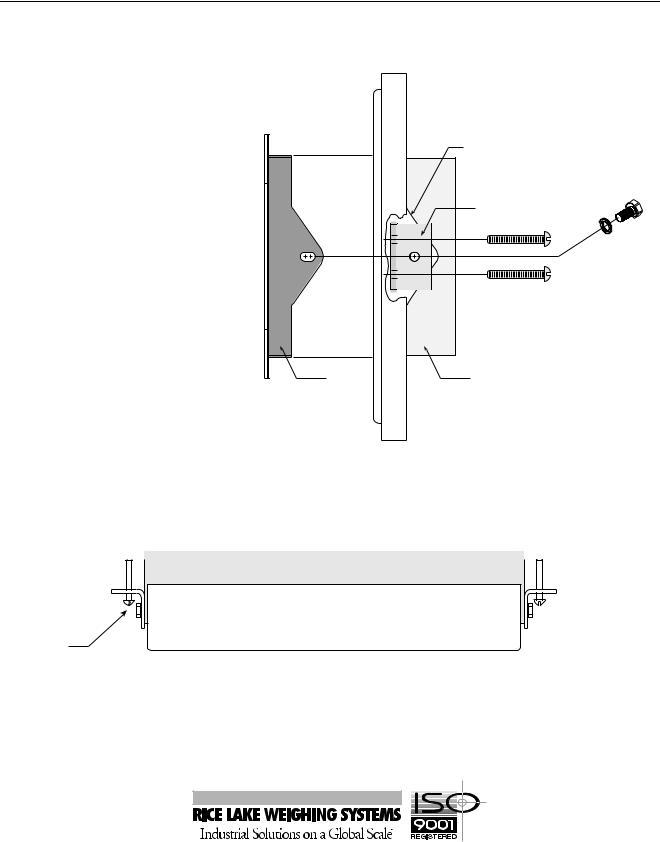
5.Use the 1/4-20 x 1/2" cap screws and lock washers provided to attach the L - brackets to the outside of the installed bezel and indicator.
E L |
|
|
NA |
Installed Bezel |
|
|
||
|
1/4-20NC x 1/2 cap screws |
|
P |
with lockwashers (2) |
|
L-Brackets (2) |
||
|
1/4-20NC x 1 3/4 machine screws (4)
Bezel |
Indicator |
6. Start the four 1/4-20NC x 1 3/4" round-head machine screws into the panel mount brackets. Place a
few drops of a removable-strength thread adhesive (such as Loctite® ) on the screw threads to prevent loosening in high-vibration environments. Tighten screws until the indicator is held securely against the panel. Figure 2 shows a top view of a completed panel mount installation.
 Panel
Panel
Bezel and gasket assembly
Indicator
L-Bracket
Figure 2. Panel Mounted IQ plus 355 (Top View)
See the IQ plus 355 Installation Manual, PN 51980, for more information about installation procedures and requirements.
October 1999 |
53172 |
 Loading...