


 Loading...
IQ 700
Digital Weight Indicator
Installation Manual
16821

Contents
About This Manual ................................................................................................................................... |
1 |
|||
1.0 |
Introduction.................................................................................................................................. |
1 |
||
|
1.1 |
Front Panel Keypad and Annunciators................................................................................................ |
2 |
|
2.0 |
Installation and Wiring ................................................................................................................ |
4 |
||
|
2.1 |
Unpacking and Assembly ................................................................................................................... |
4 |
|
|
2.2 |
Enclosure Disassembly....................................................................................................................... |
4 |
|
|
2.3 |
Cable Connections............................................................................................................................. |
4 |
|
|
2.4 |
Power Connections ............................................................................................................................ |
4 |
|
|
|
2.4.1 |
AC Units ..................................................................................................................................................... |
4 |
|
|
2.4.2 |
VAC Conversion ........................................................................................................................................ |
4 |
|
2.5 |
Board Removal .................................................................................................................................. |
5 |
|
|
2.6 |
Replacement Parts............................................................................................................................. |
5 |
|
|
2.7 |
Instrumentation Setup ........................................................................................................................ |
5 |
|
|
2.8 |
Load Cell Wiring ................................................................................................................................. |
6 |
|
|
2.9 |
Standard Surge Protection Board....................................................................................................... |
7 |
|
|
2.10 Serial Port Wiring .............................................................................................................................. |
8 |
||
|
|
2.10.1 Serial Port #1 Wiring: CPU KGR8924–1..................................................................................................... |
9 |
|
|
|
2.10.2 Serial Port #2 Wiring: CPU KGR8924–1................................................................................................... |
10 |
|
|
2.11 Digital I/O Wiring ............................................................................................................................. |
10 |
||
3.0 |
Configuration.............................................................................................................................. |
12 |
||
|
3.1 |
Digital Configuration ......................................................................................................................... |
12 |
|
|
|
3.1.1 |
Parameter Overview ................................................................................................................................. |
12 |
|
|
3.1.2 |
Configuration Procedure........................................................................................................................... |
12 |
|
|
3.1.3 |
Digital Configuration Parameters............................................................................................................... |
12 |
|
|
3.1.4 |
Normal Configuration Setup Parameters................................................................................................... |
18 |
|
3.2 |
Serial Configuration .......................................................................................................................... |
19 |
|
4.0 |
Options Configuration ................................................................................................................ |
21 |
||
|
4.1 |
Option 1 – Expanded Resolution ...................................................................................................... |
22 |
|
|
4.2 |
Option 2 – Analog Output Option ..................................................................................................... |
23 |
|
|
|
4.2.1 |
Specifications ........................................................................................................................................... |
23 |
|
|
4.2.2 |
Test Modes .............................................................................................................................................. |
23 |
|
|
4.2.3 |
Error Checking ......................................................................................................................................... |
23 |
|
|
4.2.4 |
Communication Verification ...................................................................................................................... |
23 |
|
|
4.2.5 |
Analog Wiring to Host Indicator ................................................................................................................ |
26 |
|
|
4.2.6 |
Analog Module Serial Pass-Through ......................................................................................................... |
26 |
|
4.3 |
Option 3 – Time and Date................................................................................................................. |
27 |
|
|
4.4 |
Option 4 – Accumulator.................................................................................................................... |
28 |
|
|
4.5 |
Option 5 – Expanded Serial Communications................................................................................... |
29 |
|
|
4.6 |
Option 6 – Linear Calibration ............................................................................................................ |
31 |
|
|
4.7 |
Option 7 – Serial I/O ......................................................................................................................... |
32 |
|
|
|
4.7.1 |
Customizing Files...................................................................................................................................... |
32 |
|
|
4.7.2 |
Macro File Setup ...................................................................................................................................... |
34 |
|
|
4.7.3 |
Standard Serial Configuration ................................................................................................................... |
35 |
|
|
4.7.4 |
Option 7 Configuration.............................................................................................................................. |
35 |
|
4.8 |
Option 8 – Analog Output/Relay Option............................................................................................ |
37 |
|
|
|
4.8.1 |
Analog Output Option Wiring .................................................................................................................... |
37 |
|
4.9 |
Option 9 – Front Panel Key Lockout Option...................................................................................... |
38 |
|
Copyright © 2001 Rice Lake Weighing Systems. All rights reserved. Printed in the United States of America.
Specifications subject to change without notice.
December 2001
i

4.10 |
Option 10 |
– Setpoints ..................................................................................................................... |
39 |
4.11 |
Option 11 |
– Remote Input Option.................................................................................................... |
39 |
4.12 |
Additional Options........................................................................................................................... |
40 |
|
4.12.1 Relay Output Board KHL8924................................................................................................................. |
40 |
||
4.12.2 Relay Output/Input Board (KJN8924–) .................................................................................................... |
42 |
||
4.12.3 Serial Command Option Parameters ....................................................................................................... |
45 |
||
5.0 |
Calibration.................................................................................................................................. |
46 |
|
|
5.1 |
Zero Calibration ................................................................................................................................ |
46 |
|
5.2 |
Single Slope Span Calibration........................................................................................................... |
46 |
|
5.3 |
Five-Point Linear Calibration ............................................................................................................. |
47 |
6.0 |
Normal Weighing Mode Operations .......................................................................................... |
48 |
||
|
6.1 |
Display Test...................................................................................................................................... |
48 |
|
|
|
6.1.1 |
Display Check .......................................................................................................................................... |
48 |
|
|
6.1.2 |
EPROM Verification .................................................................................................................................. |
48 |
|
6.2 |
LED Annunciators............................................................................................................................. |
48 |
|
|
6.3 |
Function Keys................................................................................................................................... |
48 |
|
|
6.4 |
Gross/Tare/Net Weighing Operations ............................................................................................... |
48 |
|
|
|
6.4.1 |
Display Mode on Power Up...................................................................................................................... |
48 |
|
|
6.4.2 |
ZERO Key Function.................................................................................................................................. |
48 |
|
|
6.4.3 |
TARE Key Function .................................................................................................................................. |
49 |
|
|
6.4.4 |
Overload and Underrange Conditions....................................................................................................... |
49 |
|
6.5 |
Fixed Tare Entry................................................................................................................................ |
49 |
|
|
|
6.5.1 |
Lb/Kg Conversion .................................................................................................................................... |
49 |
|
6.6 |
Serial Output .................................................................................................................................... |
50 |
|
|
|
6.6.1 |
Serial Data Formats.................................................................................................................................. |
50 |
|
|
6.6.2 |
Demand Mode versus Continuous Data Output ....................................................................................... |
51 |
|
|
6.6.3 |
Demand Print with Identification Number.................................................................................................. |
51 |
|
6.7 |
Truck Weighing Mode....................................................................................................................... |
52 |
|
7.0 |
Setpoints .................................................................................................................................... |
54 |
||
8.0 |
Optional and Advanced Features ............................................................................................... |
61 |
||
|
8.1 |
Expanded Serial Communications .................................................................................................... |
61 |
|
|
|
8.1.1 |
Demand Output Serial Data Format.......................................................................................................... |
61 |
|
|
8.1.2 |
Continuous Condec Output Serial Data Format........................................................................................ |
62 |
|
|
8.1.3 |
RS485 Data Formats................................................................................................................................ |
62 |
|
|
8.1.4 |
Port 1 Remote Serial Commands ............................................................................................................. |
63 |
|
|
8.1.5 |
Full Duplex Parameter Entry/Recall........................................................................................................... |
64 |
|
8.2 |
Delay Demand Print.......................................................................................................................... |
64 |
|
|
8.3 |
Battery Option .................................................................................................................................. |
64 |
|
9.0 |
Appendix .................................................................................................................................... |
65 |
||
|
9.1 |
ASCII Character Chart ...................................................................................................................... |
65 |
|
|
9.2 |
Parameter Control Code Chart ......................................................................................................... |
66 |
|
|
9.3 |
Display and Error Messages ............................................................................................................. |
66 |
|
|
9.4 |
Specifications ................................................................................................................................... |
67 |
|
IQ 700 Limited Warranty ........................................................................................................................ |
69 |
|||
ii |
IQ 700 Installation Manual |

About This Manual
The IQ 700 indicator represents the latest in state-of-the-art microprocessor technology specifically applied to the weighing marketplace. This manual provides information on installation, calibration, configuration, and operation of the IQ 700.
Authorized distributors and their employees can view or download this manual from the Rice Lake Weighing Systems distributor site at www.rlws.com.
1.0Introduction
The IQ 700 is a single-channel digital weight indicator designed to operate in a wide variety of scale and weighing applications. The indicator is housed in a NEMA 4X stainless steel sealed case. The standard unit is equipped with a tilt stand base for tabletop or wall mounting applications. The indicator front panel consists of a 21-button keypad, six seven-segment display digits, and six LED annunciators (see Figure 1-1 on page 2).
Features of the IQ 700 include:
•Full front panel digital configuration and calibration.
•Zero and span temperature compensation to ensure compliance with NTEP and Canadian temperature range requirements (–10 to 40°C).
•Nonvolatile memory stores data for calibration, temperature compensation, configuration parameters, auto or fixed tare values, PAZ and AZM values, and setpoint values.
•10,000 displayed graduations in legal-for-trade applications; 80,000 displayed graduation in non-legal-for-trade, process weighing applications.
NOTE: Use of more than 20,000 graduations may cause undesirable display instability in some applications.
•Analog sensitivity to 0.3 V/grad at 20,000 graduations.
•Ten updates per second, with selectable digital averaging and auto averaging; 5 Hz active analog filter for smooth response.
•Excitation for eight 350Ω load cells at 10VDC.
•Time and date print selection.
Introduction 1
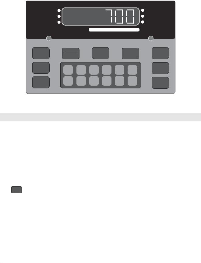
1.1Front Panel Keypad and Annunciators
Figure 1-1 shows the IQ 700 front panel. The IQ 700 display consist of six seven-segment display digits. Table 1-1 lists the front panel keys and their functions.
ZERO |
lb |
NET |
kg |
GROSS |
MOTION |
CAPACITY |
5000 lb. X 0.5 |
|
|
|
|
|
|
|
ZERO |
NET |
|
TARE |
|
lb/kg |
||
|
|
|
GROSS |
|
CONV |
|||||
|
|
|
|
|
|
|
|
|||
|
|
|
TARE |
1 |
2 |
3 |
4 |
5 |
|
1 SET |
|
|
|
RECALL |
CE |
POINT |
|||||
|
|
|
|
|
||||||
|
|
|
M O D E L |
6 |
7 |
8 |
9 |
0 |
ENT |
2 SET |
|
|
|
700 |
|||||||
|
|
|
|
|
|
|
|
|
POINT |
|
|
|
|
|
|
Figure 1-1. IQ 700 Front Panel |
|
||||
|
|
|
|
|
|
|
|
|
|
|
Panel Key |
|
|
|
|
|
Function |
|
|
||
|
|
|
|
|||||||
ZERO |
Provides push-button auto zero (PAZ) over ±1.9% or 100% full scale capacity. Operates only in gross |
|||||||||
|
|
|
weighing mode. |
|
|
|
|
|
|
|
|
|
|
|
|
||||||
GROSS/NET |
Switches the unit between gross and net weighing modes. |
|
||||||||
|
|
|
|
|||||||
TARE |
Provides push-button tare entry over 100% of scale capacity. Pressing TARE key switches to net mode |
|||||||||
|
|
|
and enters tare. |
|
|
|
|
|
|
|
|
|
|
|
|||||||
Provides a manual print function if unit is wired to serial printer or other data device. Also initiates truck |
||||||||||
|
|
|
in/out weighing function if that feature is enabled. See Section 4.7 on page 31 for serial output |
|||||||
|
|
|
specifications. |
|
|
|
|
|
|
|
|
|
|
|
|
||||||
lb/kg CONV |
Switches the displayed weight unit between pounds and kilograms. |
|
||||||||
|
|
|
|
|||||||
TARE RECALL |
Press to recall tare value; LED annunciator lit when tare value is displayed. Also used as ID RECALL in |
|||||||||
|
|
|
truck weighing mode and recalls total value when the totalizer option is enabled. |
|||||||
|
|
|
|
|
|
|
|
|
||
ON/OFF |
Provides power to the indicator. |
|
|
|
|
|
||||
|
|
|
NOTE: On AC units, the ON/OFF switch is replaced by the Model 700 |
which becomes a start key in |
||||||
|
M O D E L |
|
||||||||
|
700 |
|
setpoint batching modes. |
|
|
|
|
|
|
|
|
|
|
|
|
|
|
|
|
|
|
SETPOINT 1 & 2 |
Push to enter or recall associated setpoint values. |
|
|
|||||||
|
|
|
|
|||||||
0–9, CE, ENT |
Numeric keyboard for entry of manual tare, setpoint values, and calibration data. CE (Clear Entry) and |
|||||||||
|
|
|
ENT (Enter) keys. |
|
|
|
|
|
|
|
|
|
|
|
|
|
|||||
|
|
|
|
Table 1-1. Front Panel Key Functions |
|
|||||
2IQ 700 Installation Manual

Table 1-2 summarizes the front panel annunciator functions.
Annunciator |
Function |
|
|
ZERO |
On when scale weight is within ±0.25 displayed graduations of zero. Used in gross or net weighing mode. |
|
|
NET |
On when the indicator is in net weighing mode. |
|
|
GROSS |
On when the indicator is in gross weighing mode. |
|
|
lb/kg |
lb or kg LED is lit to show the current displayed weight units. |
|
|
MOTION |
On when scale is in motion. |
|
|
1 SETPOINT |
On when the appropriate setpoint is energized or are flashing when the appropriate setpoint is recalled on |
2 SETPOINT |
the display. |
|
|
TARE RECALL |
Part of the TARE RECALL key, LED flashes when tare value is displayed. |
|
|
|
Table 1-2. Front Panel Annunciators |
Introduction 3
2.0Installation and Wiring
This section describes the procedures for connecting load cell and serial communications cables to the IQ 700 indicator. Instructions for CPU board replacement are included, along with assembly drawings and parts list for the service technician.
Use a wrist strap to ground youself ! Caution and protect components from
electrostatic discharge (ESD) when working inside the indicator.
2.1Unpacking and Assembly
All indicators are configured and tested prior to shipment to ensure that they are fully functional.
Immediately after unpacking, visually inspect the IQ 700 to ensure all components are included and undamaged. The shipping carton should contain the indicator with attached tilt stand, this manual, and a parts kit. If any parts were damaged in shipment, notify Rice Lake Weighing Systems and the shipper immediately.
2.2Enclosure Disassembly
The indicator enclosure consists of a load cell connector and cord grips for communication cables. The enclosure must be opened to connect the communication cables.
The IQ 700 has no on/off switch.
Warning Before opening the unit, ensure the power cord is disconnected from the
power outlet.
Ensure power to the indicator is disconnected then remove the screws that hold the enclosure body. Place the indicator face-down on an antistatic work mat, then lift the enclosure away from the front bezel. Set the enclosure aside.
2.3Cable Connections
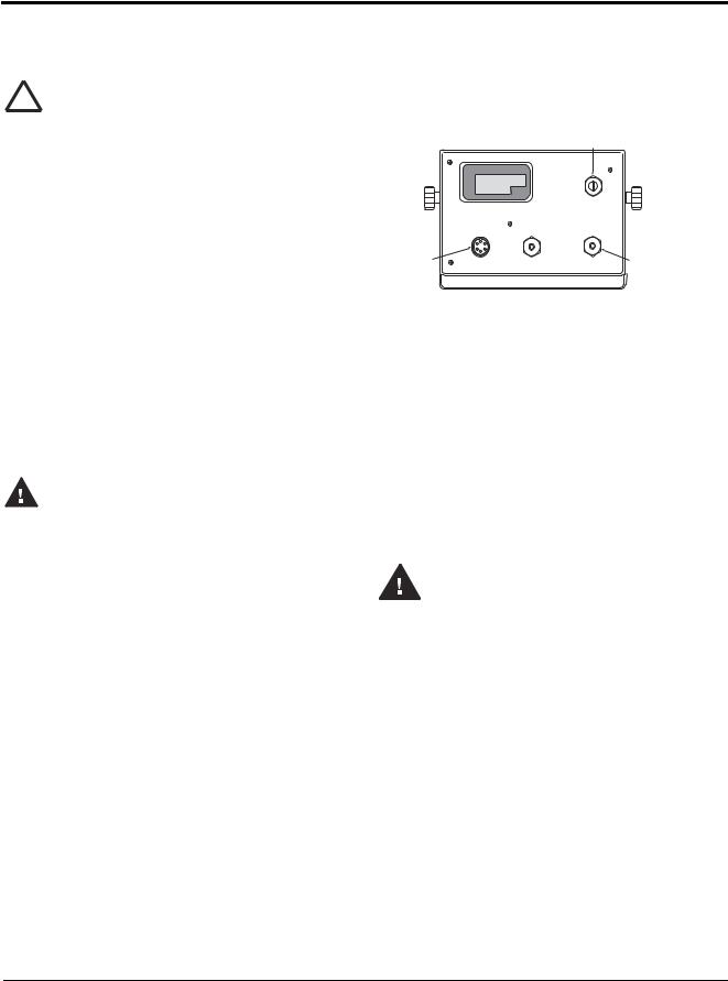
The IQ 700 provides a load cell connector and three cord grips for cabling into the indicator; one for the power, two to accomodate communications, digital input, and analog output cables.
One of the two free cord grips comes with a plug installed to prevent moisture from entering the enclosure. Depending on your application, remove the plug from the appropriate cord grip and install cables as required.
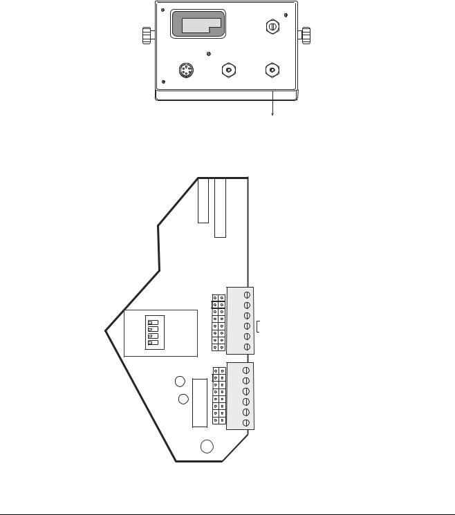
Figure 2-1 shows the recommended assignments for the IQ 700.
REAR VIEW
Analog Output, Digital Input
|
|
|
TB3 & 5 |
|
Load Cell |
TB1 |
AC Power |
TB2 & 4 |
Serial Communications |
Connector |
|
Figure 2-1. IQ 700 Backplate
2.4Power Connections
Standard units are powered by either 115 or 230 VAC volts or by optional battery pack.
2.4.1AC Units
Units are powered by standard AC power. The AC power cord must be plugged into a 3-prong grounded AC wall socket.
2.4.2VAC Conversion
The IQ 700 can be converted from 115VAC to 230VAC. The following steps are necessary to complete this conversion.
Before beginning, disconnect the Warning AC power source. Failure to do so
can result in injury or death.
1.Disconnect the power source from the unit.
2.Remove rear outer case of the IQ 700.
3.Remove the rear connector bracket, remove the four corner screws from the standoffs, then remove the four screws from the corners of the CPU board.
4.Remove the CPU assembly.
5.Remove the protective insulator panel from the
solder side of the CPU board.
4IQ 700 Installation Manual
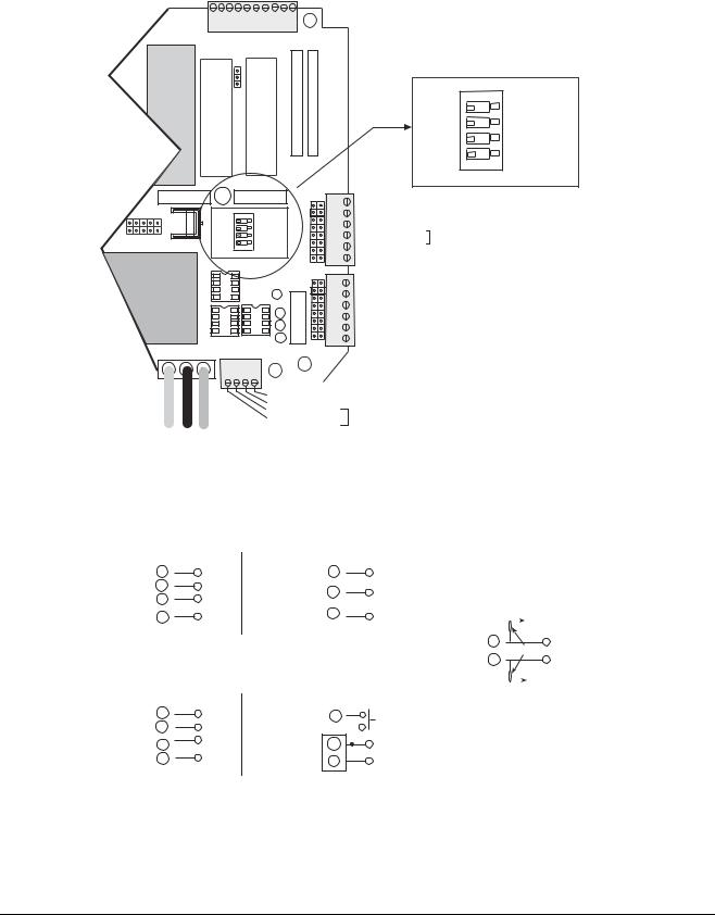
6.Cut circuit traces between E7/E8 and E9/E10 as indicated with a sharp instrument like a razor blade or an X-acto® knife. Refer to Figure 2-2.
Converting from 115V AC to 230V AC
Cut between |
Jumper E8 to E9 |
Cut between |
|||
E7 and E8 |
E9 and E10 |
||||
|
|
|
|||
E7 |
E8 |
E9 |
E10 |
|
|
Circuit Side of CPU Board
Figure 2-2. Circuit Trace Setup
7.Add jumper, E8 to E9 using a properly insulated wire with a minimum size of #22 AWG.
8.Replace the protective insulator panel.
9.Change the power cord.
10.Reassemble the unit, test, and label unit for 230VAC.
2.5Board Removal
If you must remove the IQ 700 CPU board, use the following procedure:
1.Disconnect power to the indicator. Loosen cord grips and remove enclosure as described in Section 2.2.
2.Unplug all connections to the CPU board.
3.Remove the four corner screws from the standoffs.
4.Remove the four screws from the corners of the CPU board.
5.Remove the CPU board from the enclosure.
To replace the CPU board, reverse the procedure. Be sure to reinstall cable ties to secure all cables inside the indicator enclosure. Replace the enclosure and torque screws.
2.6Replacement Parts
Table 2-1 lists the replacement parts for the IQ 700.
19571 AC CPU RFI assembly
19573 LED display board
19574 21-keyboard assembly
19404 Overlay
19600 LCD display board
Table 2-1. IQ 700 Replacement Parts
2.7Instrumentation Setup
The IQ 700 operates with the EPROM program KDA1921-1(27C512). To verify the program installed in the indicator, turn on the indicator and observe the displayed value at the EP prompt (see Figure 2-3). The EP prompt displays the family, set, and version level of the installed EPROM.
EP–1.15
EPROM Set 1 Version 15
Figure 2-3. EPROM Display
To ensure that the IQ 700 is in proper operating condition, the indicator can be tested with a load cell simulator. The input signal should be as close as possible to the normal system millivolt value. Figure 2-4 shows the simulator-to-indicator wiring connection in a six-wire configuration. See Section 2.8 on page 6 for more information.
NOTE: Six-wire configuration requires that the +SEN lead be shorted to +EXC and the –SEN lead be shorted to –EXC at the simulator only.
LOAD CELL
SIMULATOR
|
–EXC |
|
–EXC |
|
|
|
|
|
|
|
–SEN |
|
|
|
|
||
|
|
|
|
|
|
|
||
|
+EXC |
|
+EXC |
|
|
|
|
|
|
|
+SEN |
|
|
|
|
||
|
|
|
TO J1 |
|
IQ700 HB |
|
||
|
|
|
|
|
|
|||
|
+SIG |
|
+SIG |
CONNECTOR |
|
|
|
|
|
|
|
|
|
|
|
||
|
–SIG |
|
–SIG |
|
|
|
|
|
|
|
|
|
|
|
|||
|
|
|
|
|
|
|
||
|
|
|
||||||
|
Figure 2-4. Wiring Connection to Simulator |
|||||||
! |
Caution |
Exceeding rated load |
cell load or |
|||||
shorting |
excitation |
wires may |
||||||
|
|
|
||||||
damage power supply.
Installation and Wiring |
5 |
NOTES:
Unprotected cable runs need to be installed in a method to protect the cable from damage from crimping.
All wiring must conform to the National Electrical Code and RP 12.6.
2.8Load Cell Wiring
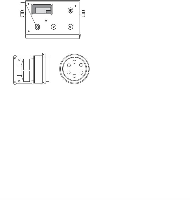
Units are equipped with a six-wire load cell connection. Figure 2-5 shows the load cell output connector and the location of TB1 on the back of the indicator. Table 2-2 (in the following column), shows load cell connector pin assignments.
J1
Load Cell
Connector
TB3 & 5
Pin |
Function |
|
|
A |
+EXCITATION |
|
|
B |
–EXCITATION |
|
|
C |
+SIGNAL |
|
|
D |
–SIGNAL |
|
|
E |
+SENSE |
|
|
F |
–SENSE |
|
|
Table 2-2. Load Cell Connector Pin Assignments
TB1 |
POWER TB2 & 4 |
|
REAR VIEW |
A
F B
E C
D
Figure 2-5. J1 Load Cell Connector
6IQ 700 Installation Manual
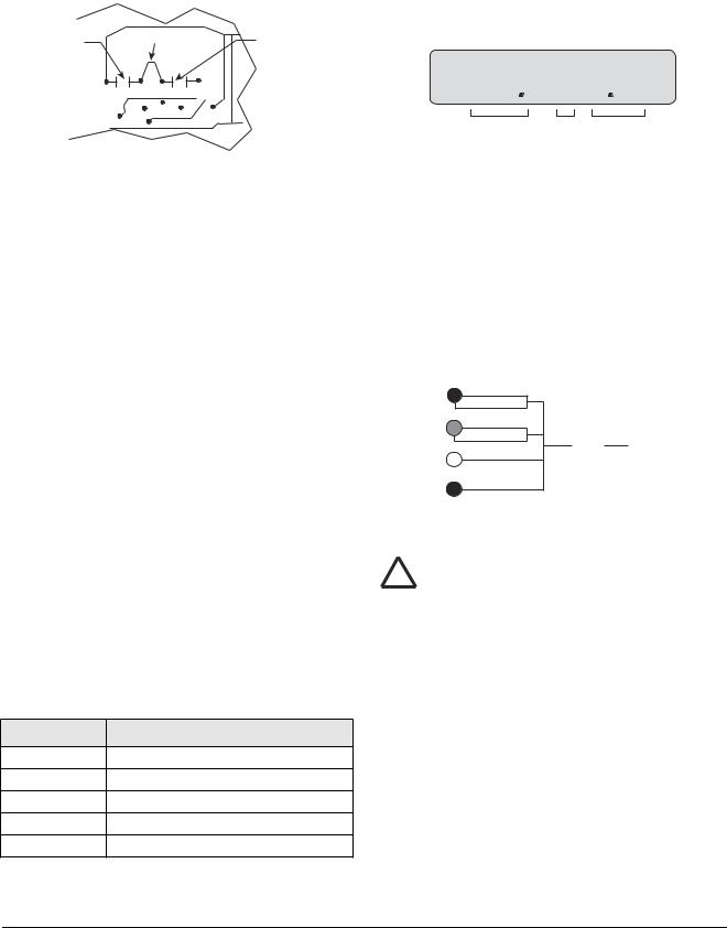
The standard connection is designed for 4-wire (non remote sensing) use. To convert to 6-wire (remote sensing) applications, cut the two PC traces on either end of TB1 as shown in Figure 2-6.
Traces
TB1
+EXC
+SEN
+SIG
–SIG
–SEN
–EXC
Traces
J5
1 |
LOAD |
2 |
|
3 |
CELL |
6 5 4 |
CONNECTOR |
J3
S3
U18 |
K1 |
J7 |
Check load cell |
|
|
|
|
|
|
|
color code for |
|
|
|
proper wiring. |
|
Q5 |
|
|
U2
F1 |
J6 |
GND |
LO HI |
|
|
|
|
1 |
2 |
|
+ Batt - |
|
TB5 |
|
|
|
|
||
TO POWER SUPPLY
Figure 2-6. Load Cell Wiring From Indicator
NOTE: The load cell shield wire should be connected
to one of the load cell cable clamp screws located on Six-Pin Female the load cell mating connector.
Shielding is connected at only one end ! Caution (typically at the indicator end). If
connected at the strain gauge end, disregard Figure 2-7.
Figure 2-7. Load Cell Shield Wire Connection
2.9Standard Surge Protection Board
The IQ 700 digital indicator comes with a factory installed surge suppression board. The suppression board stops the flow of excess voltage to the CPU board and attaches to TB1 on the CPU board just by pressing it onto TB1 and tightening the connector screws.
COMPONENT SIDE
CR3 |
CR4 |
CR2 |
CR1 |
RIGHT SIDE |
CIRCUIT SIDE |
+EXC |
E1 |
|
+SENSE |
E2 |
|
|
|
|
+SIG |
E3 |
E7 |
–SIG |
E4 |
CHGND |
|
||
–SENSE |
E5 |
|
–EXC |
E6 |
|
|
|
Figure 2-8. Surge Protection Diagram
Installation and Wiring |
7 |
2.10 Serial Port Wiring
The IQ 700 serial port can be configured to communicate directly to a printer, remote display, or other device using 20 mA active/passive, RS-232, or RS-485.
Access to this serial communication port is through the water seal cap (TB2 and TB4) located on the back of the IQ 700 indicator (see Figure 2-9). Wiring is extended through this connector and wired inside the indicator. See the output connector diagram in Figure 2-10 for connector and wire identification. Select the appropriate terminals and set switch S1 accordingly.
TB3 & 5
TB1 |
POWER TB2 & 4 |
S1
PASS PORT 1
REAR VIEW
Serial Port
Connection
Figure 2-9. Serial Port TB2 Location
U9
U13
J11
1 |
RS232 |
2 |
20MA |
3 |
RS485 |
4 |
ACTIVE |
RECEIVE
J10
U8
SERIAL COMMUNICATIONS - 2 SERIAL COMMUNICATIONS - 1
6
5
4
3
2
1
1
6
5
4
3
2
1
TB4
RX+ (20 mA passive Port 1)
RX- (20 mA passive Port 1) RX+ (20 mA active Port 1)
TX- (20 mA Port 2)
TX+ (20 mA Port 2)
TX- (20 mA active Port 1)
GND or RX 20 mA active Port 1
TX+ (20 mA active Port 1)
RX1 (RS-232 duplex Port 1) RD1
TX1 (RS-232 duplex Port 1) TD1
TX2 (RS-232 Port 2) TD2
TB2
Figure 2-10. Serial I/O Wiring Locations
8IQ 700 Installation Manual
2.10.1Serial Port #1 Wiring: CPU KGR8924–1
Serial Port 1 is a bidirectional (full duplex) port supporting active/passive 20 mA, current loop, RS-232, or RS-485 communications.
TB3
10 9 8 7 |
6 |
5 |
4 |
3 |
2 |
11 |
DIGITAL OUTPUT |
|
|
|
|||
U9 U13
U7 U4 U11
U10 |
C15 |
|
U19 |
J11 |
1 |
|
|
|
- |
6 |
|||
|
|
432 1 |
|
|
COMMUNICATIONS |
|
|
S1 |
ACTIVE |
|
5 |
||
U1 |
|
|
RS232 |
|
|
4 |
|
|
|
20MA |
|
|
|
|
|
|
RS485 |
|
|
3 |
|
PASS |
|
|
|
SERIAL |
2 |
|
PORT 1 |
|
RECEIVE |
|
1 |
|
|
|
|
|
1 |
||
|
|
|
|
J10 |
2 |
6 |
|
|
|
|
|
- |
|
|
|
U15 |
|
COMMUNICATIONS |
||
|
|
|
5 |
|||
|
|
|
|
|||
|
|
|
|
|
|
|
|
|
|
|
|
|
4 |
|
|
|
|
U8 |
|
3 |
|
|
|
|
|
SERIAL |
2 |
|
U22 |
U21 |
|
1 |
||
GND LO HIJ2
DIGITAL OUTPUT
11 |
2 |
3 |
4 |
|
|
|
|
S1
PASS
PORT 1
TB4
RX+ 20 mA passive port 1
RX20 mA passive port 1
RX+ 20 mA active port 1
TX20 mA port 2
TX+ 20 mA port 2
TX20 mA active port 1
GND or RX 20mA active port 1
TX+ 20mA active port 1
RX1 RS-232 duplex port 1
TX1 RS-232 duplex
TX2 RS-232 port 2
TB2
4 3 2 1
RS232
20MA
RS485 ACTIVE
RECEIVE
TB5
TO POWER SUPPLY
TX20 mA active port 2 TX+ 20 mA passive port 2
TX20 mA passive port 1
RS-485
TX+ 20 mA passive port 1
NOTE:
Passive 20mA requires U22 option RS-485 option requires U21
Figure 2-11. Serial Port #1 Switch Location
|
ACTIVE 20 mA |
|
|
RS232 DUPLEX |
|
|
|
|
|
|
|
|
||||||||
|
TB2 |
|
|
|
|
|
TB2 |
|
|
|
|
|
|
|
|
|
|
|
|
|
TX- |
6 |
|
RX-(passive) |
|
COM |
5 |
|
|
|
SIG COM |
|
|
|
|
|
|
|
|
|
|
RX- |
5 |
|
TX- |
|
RX1 |
3 |
|
|
|
Tx |
|
|
|
|
|
|
|
|
|
|
TX+ |
4 |
|
RX+ |
|
|
|
|
|
|
|
|
|
|
|
|
|
||||
|
|
|
|
|
|
|
|
|
|
|
RS485 |
|||||||||
RX+ |
|
|
TX+ |
|
TX1 |
2 |
|
|
|
Rx |
|
|
|
|||||||
3 |
|
|
|
|
|
|
|
|
|
|
|
GND |
|
|
||||||
|
TB4 |
|
|
|
|
|
|
|
|
|
|
|
|
TB5 |
|
|
|
|
|
|
PORT 1 |
S1 – 2, 4 CLOSED |
|
PORT 1 |
|
S1 – 1 CLOSED |
A |
1 |
100 k Ohm |
A |
|
||||||||||
|
|
S1 – 1, 3 OPEN |
|
|
|
|
S1 – 2, 3, 4 OPEN |
B |
2 |
B |
|
|||||||||
|
|
|
|
|
|
|
|
|
|
|
||||||||||
|
PASSIVE 20 mA |
|
|
RS232 SIMPLEX |
|
|
|
|
+5 |
|
|
|||||||||
|
|
|
PORT 1 |
MASTER |
|
|||||||||||||||
|
|
|
|
|
||||||||||||||||
|
|
|
|
|
|
|
|
|||||||||||||
|
|
|
|
|
|
|
|
|
|
|
|
|
|
|
|
|
|
|||
TX+ |
TB5 |
|
|
|
|
|
TB3 |
|
|
|
|
|
100 |
|
|
|
|
|
|
|
1 |
|
RX+ |
|
10 |
|
|
|
REMOTE |
kOhm |
|
OPTION 5 ON |
|||||||||
TX- |
2 |
|
RX- (active) |
|
|
|
|
|
|
|
|
|
|
|
S1 – 3 CLOSED |
|||||
|
|
|
|
|
|
|
|
|
|
|
||||||||||
RX- |
3 |
|
TX- |
COM |
5 |
|
|
|
SIG COM |
|
|
|
|
S1 – 1, 2, 4 OPEN |
||||||
|
|
|
|
|
|
|
|
|
|
|
|
|
||||||||
|
|
|
|
|
|
|
|
|
|
|
|
|
|
|
||||||
RX+ |
4 |
|
TX+ |
|
TX1 |
2 |
|
|
|
Rx |
|
|
|
|
|
|
|
|
|
|
|
TB4 |
|
|
|
|
|
TB2 |
|
|
|
|
|
|
|
|
|
|
|
|
|
|
|
|
|
|
|
|
|
|
|
|
|
|
|
|
|
|
|
|
||
|
|
|
|
|
|
|
|
|
|
|
|
|
|
|
|
|
|
|
||
PORT 1 |
|
|
|
|
|
|
|
|
|
|
|
|
|
|
|
|
|
|
||
S1 – 2 CLOSED |
|
PORT 1 |
|
S1 – 1 CLOSED |
|
|
|
|
|
|
|
|
||||||||
|
|
S1 – 1, 3, 4 OPEN |
|
|
|
|
S1 – 2, 3, 4 OPEN |
|
|
|
|
|
|
|
|
|||||
Figure 2-12. Port #1 Switch Settings
NOTE: The pull-up and pull-down resistors shown in the RS485 wiring diagram (100 KΩ typical) should be installed at the indicator. GND may be tied to TB2-5 and +5 VDC to TB2-4 on CPU board (KGR8924-).
Installation and Wiring |
9 |
2.10.2Serial Port #2 Wiring: CPU KGR8924–1
Serial port #2 is a simplex port using RS232, or 20 mA active/passive (passive 20 mA requires U15 installed) communication.
|
RS232 |
|
|
20 mA active |
|
20 mA passive |
||
|
TB2 |
|
|
TB4 |
|
|
TB5 |
|
COM |
5 |
SIG COM |
TX+ |
1 |
Rx+ |
TX+ |
3 |
Rx+ |
TX2 |
1 |
Rx |
active |
|
passive |
TX- |
4 |
active |
TX- |
2 |
Rx - |
Rx- |
|||||
PORT 2 |
|
PORT 2 |
|
PORT 2 |
|
|||
Figure 2-13. Port #2 Switch Settings
2.11 Digital I/O Wiring
The standard unit has four outputs for setpoint and zero band control and four discrete inputs that allow the zero, net/gross, and print function to be operated remotely by contact closure of these inputs to digital ground. Wire any active digital input and outputs to connector TB3 on the CPU board. Table 2-3 shows the digital I/O assignments for the TB3 connector and their description.
|
|
Description |
|
|
|
|
|
|
|
TB3 Pin |
Signal |
Outputs |
|
|
|
|
|
|
|
1 |
+5 VDC |
|
|
|
|
|
|
||
2 |
DIG OUT 4 |
Dribble control assigned to setpoint 2 (defined in parameter 11), or a zero band output |
||
|
|
when parameter 12 is selected for 1-50. |
|
|
|
|
|
|
|
3 |
DIG OUT 3 |
Setpoint 2 output (defined in parameter 11). |
|
|
|
|
|
||
4 |
DIG OUT 2 |
Dribble control assigned to setpoint 1 (defined in parameter 11). |
||
|
|
|
|
|
5 |
DIG OUT 1 |
Setpoint 1 output (defined in parameter 11). |
|
|
|
|
|
|
|
|
|
Inputs |
|
|
|
|
|
|
|
|
|
Normal Mode |
|
Batch Mode |
|
|
|
|
|
6 |
GND |
|
|
|
|
|
|
|
|
7 |
DIG IN 1 |
Net/gross |
|
Abort |
|
|
|
|
|
8 |
DIG IN 2 |
Zero |
|
Zero |
|
|
|
|
|
9 |
DIG IN 3 |
Tare |
|
Start Batch |
|
|
|
|
|
10 |
DIG IN 4 |
|
||
|
|
|
|
|
Table 2-3. TB3 Pin Assignments (Digital I/O)
Inputs 7 through 10 allow the zero, net/gross, tare, and print functions to be operated remotely by contact closure of these inputs to digital ground.
10 IQ 700 Installation Manual

Typically, digital outputs control relays which operate other equipment. Outputs 1 through 4 allow for setpoint and zero band control.
Operational Mode |
|
TTL Inputs J11 |
|
|
|
|
|
Normal |
Batch |
Relay Board TB3 |
KGR8924 CPU |
|
|
|
|
Tare |
Start Batch |
TB3-6 |
IN2 |
|
|
|
|
Zero |
Zero |
TB3-5 |
IN3 |
|
|
|
|
Net/Gross |
Abort |
TB3-4 |
IN4 |
|
|
|
|
TB3-3 |
IN5 |
||
|
|
|
|
Table 2-4. Relay Input Wiring
Installation and Wiring |
11 |
3.0Configuration
Prior to calibration, the IQ 700 must be digitally configured, or assigned a set of operating parameters. The three parameters listed in Section 3.1 are directly related to calibration and must be set before proceeding to calibration mode.
3.1Digital Configuration
3.1.1Parameter Overview
Table 3-1 on page 13 lists configuration parameters and describes their values. The following paragraphs give the procedure for configuring the IQ 700.
3.1.2Configuration Procedure
1.Unscrew the two screws on the face plate bracket (Figure 3-1). The bracket drops down, exposing four program switches on the left.
ZERO |
lb |
NET |
kg |
GROSS |
MOTION |
CAPACITY |
5000 lb. X 0.5 |
1 |
2 3 4 |
OPEN |
|
ZERO |
NET |
|
TARE |
|
lb/kg |
|||
GROSS |
|
|
CONV |
|||||
|
|
|
|
|
|
|||
TARE |
1 |
2 |
3 |
4 |
5 |
|
1 SET |
|
RECALL |
CE |
POINT |
||||||
|
||||||||
M O D E L |
6 |
7 |
8 |
9 |
0 |
ENT |
2 SET |
|
700 |
||||||||
|
|
|
|
|
|
POINT |
||
Figure 3-1. Accessing the Program Switches
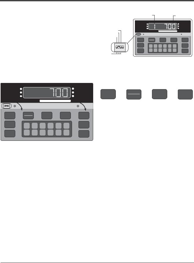
2.Temporarily remove the unit’s flexible black display panel by gently pushing down and lifting the panel up and out at its center to expose the configuration and calibration instructions printed on the surface below. The switch function table
defines the appropriate front panel switch settings for the CONF and CAL modes.
3.Close switch SW1-2, marked CONF (2), by moving to the up position (see Figure 3-2). A prompt appears with a parameter number and data value.
The parameter identifier is a number, 1–14, that correlates to the CONFIG chart on the upper left of the
switch map panel. Selected data represents the value being entered into the unit configuration data. For example, 1 100 sets the indicator to 10,000 graduations (see Table 3-2 on page 15).
When configuration is complete, set SW1-2 down to return the unit to normal operating mode.
|
|
Parameter Identifier |
|
|
|
|
Selected Data |
||
|
|
ZERO |
|
|
|
|
|
|
lb |
|
|
NET |
|
|
|
|
|
|
kg |
DEAD LOAD (3) |
|
GROSS |
|
|
|
|
|
|
MOTION |
|
|
CAPACITY |
|
5000 lb. X 0.5 |
|
|
|||
CONF (2) |
|
|
|
|
|
|
|
|
|
CAL (1) |
|
|
|
|
|
|
|
|
|
|
|
ZERO |
NET |
|
TARE |
|
lb/kg |
||
|
|
GROSS |
|
|
CONV |
||||
|
|
|
|
|
|
|
|
||
1 |
2 3 4 |
TARE |
1 |
2 |
3 |
4 |
5 CE |
1 SET |
|
OPEN |
RECALL |
POINT |
|||||||
M O D E L |
6 |
7 |
8 |
9 |
0 |
ENT |
2 SET |
||
|
|
700 |
|
POINT |
|||||
NORM
Figure 3-2. Closing Switch 2
Figure 3-3 defines the functional operation of each key on the front panel of the indicator when the unit is in the the setup mode.
ZERO |
NET |
TARE |
lb/kg |
|
GROSS |
CONV |
|||
|
|
|||
|
|
|
|
|
Zero |
Net/Gross |
Tare |
Units |
|
|
|
|
|
|
Parameter |
Parameter Data |
Subparameter |
Subparameter |
|
Select |
Select |
Select |
Data Select |
|
|
|
|
|
Figure 3-3. Front Panel Key Functions
NOTE: The TARE RECALL key functions as a previous screen key in CONFIG mode.
3.1.3Digital Configuration Parameters
Table 3-2 on page 15 lists the configuration display prompts (Prompt 1), and their value selections for displayed graduations. Prior to calibration, the IQ 700 must be digitally configured, or given its set of operating parameters. The first three parameter selections are directly related to calibration and must be set up before proceeding to the calibration mode. These parameters include;
•number of graduation
•resolution
•decimal point location in the weight data, all of which define the scale capacity.
Table 3-3 lists Prompts 2 and 3, Table 3-4 lists Prompts 4, and Table 3-4 has Prompts 5, 6, and 7. Prompts 8, 9, and 10 are shown in Table 3-5 and Prompts 11 through 14 are listed in Table 3-6 on page 17.
12 IQ 700 Installation Manual

Parameter |
Description |
Values |
|
|
|
1 |
Graduations |
NTEP to 10,000 (up to 80,000 available). |
|
|
|
2 |
Display resolution |
1, 2, 5, 10, 20, 50, 100 |
|
|
|
3 |
Decimal point |
0.0, 0.00, 0.000, 0.0000, no decimal |
|
|
|
5 |
Digital averaging |
1, 2, 4, 8, 16, 32, A1 = 8-4-2; A2 = 16-8-4 |
|
|
|
6 |
Tare mode |
ATNR, AUTO, FIXED, BOTH (inhibit with motion) |
|
|
|
7 |
AZM band |
Off, 0.5, 1, 3, 5, and 10 divisions |
|
|
Use 0.5 for H-44, bench, counter and livestock applications; use 3 for vehicle, |
|
|
axle-load, and railroad scales |
|
|
|
8 |
AZM/PAZ aperture |
±1.9%, 100% of capacity includes push-to-zero, H-44: 1.9% |
|
|
|
9 |
Motion |
Off, 1, 3, 5 divisions H-44: vehicle, axle, livestock, RR, 3.0; all other 1.0 |
|
|
|
10 |
Displayed units |
Lb, kg, con |
|
|
|
11 |
Setpoint mode |
See Section 7.0 on page 52 for settings |
|
|
|
12 |
Zero band |
Off, 1, 2, 3, 4, 5, 6, 7, 8, 9, 10, 20, 30, 40, 50 |
|
|
|
13 |
Weigh mode |
Normal, truck mode with transaction cancelled/stored, fixed/auto tare |
|
|
|
14 |
Serial output |
Port 1, Port 2, demand, continuous, baud rate, G/T/N, or display |
|
|
|
Table 3-1. Parameter Overview
Configuration 13

Figure 3-4 provides a graphic representation of configuration parameters associated with the IQ 700.
CONFIG |
CALIBR |
SERIAL |
OPTION 1 OPTION 2 |
XXXXXXXOPTION3 |
OPTION 4 OPTIONXXXXXXX5 |
OPTIONXXXXXXX6 OPTION 7 |
OPTION 8 OPTION 9 OPTION 10 OPTION 11 |
GRADS |
|
RES |
DECPT |
AVERAGE |
TARE |
AZM |
AZM/PAZ |
|
|
resolution |
decimal point |
digital average |
enable tare |
band |
band |
100 |
|
1 |
0.0 |
1 |
ATNR |
OFF |
1.9 |
selection |
|
2 |
0.00 |
2 |
AUTO |
0.5 |
FS |
list, |
|
||||||
|
|
|
|
|
|
|
|
see table 3-2 |
|
5 |
0.000 |
4 |
FIXED |
1 |
|
on page 15 |
|
|
|||||
|
|
|
|
|
|
|
|
|
|
10 |
0.0000 |
8 |
BOTH |
3 |
|
|
|
20 |
|
16 |
|
5 |
|
|
|
50 |
|
32 |
|
10 |
|
|
|
100 |
|
A1=8-4-2 |
|
|
|
|
|
|
|
A2=16-8-2 |
|
|
|
MOTION |
DISPLAY |
ST PT |
ZERO BAND |
WEIGHT |
SERIAL |
|
band |
setpoint |
control output |
mode |
serial output |
||
|
||||||
Off |
lb |
off |
Off |
normal |
port 1 & 2 |
|
|
|
|
|
|
||
1 |
kg |
SP |
1 |
truck |
demand |
|
|
|
|
|
|
||
3 |
lb. conversion |
over/under |
2 |
|
continous |
|
|
|
|
|
|
||
5 |
|
batch 1 |
3 |
|
baud rate |
|
10 |
|
batch 2 |
4 |
|
G/T/N |
|
|
|
|
|
|
||
20 |
|
modes A - G |
5 |
|
display |
|
|
|
output |
|
|
||
50 |
|
6 |
|
|
||
|
pos/neg |
|
|
|||
|
|
|
|
|
||
|
|
|
7 |
|
|
|
|
|
|
8 |
|
|
9
10
20
30
40
50
Figure 3-4. Configuration Menu
14 IQ 700 Installation Manual
|
Prompt Display |
|
Interpretation |
|
Notes |
|
|
|
|
|
|
|
|
|
|
||
Displayed Graduations |
|
|
Number of Graduations = Scale Capacity |
|
|
|||
|
|
|
|
|
Resolution |
|
|
|
1 |
5 |
|
500 |
|
|
|
||
|
|
|
|
|
|
|
|
|
1 |
10 |
|
1000 |
|
Legal for trade values: 500–10000 graduations |
|
|
|
|
|
|
|
|
|
|
|
|
1 |
15 |
|
1500 |
|
|
|
||
|
|
|
|
|
||||
|
|
|
|
|
|
|
|
|
1 |
20 |
|
2000 |
|
|
|
|
|
|
|
|
|
|
|
|
|
|
1 |
25 |
|
2500 |
|
|
|
|
|
|
|
|
|
|
|
|
|
|
1 |
30 |
|
3000 |
|
|
|
|
|
|
|
|
|
|
|
|
|
|
1 |
40 |
|
4000 |
|
|
|
|
|
|
|
|
|
|
|
|
|
|
1 |
50 |
|
5000 |
|
|
|
|
|
|
|
|
|
|
|
|
|
|
1 |
60 |
|
6000 |
|
|
|
|
|
|
|
|
|
|
|
|
|
|
1 |
80 |
|
8000 |
|
|
|
|
|
|
|
|
|
|
|
|
|
|
1 |
100 |
|
10000 |
|
|
|
|
|
|
|
|
|
|
|
|
|
|
1 |
120 |
|
12000 |
|
Not valid in legal-for-trade applications |
|
|
|
|
|
|
|
|
|
|
|
|
1 |
140 |
|
14000 |
|
|
|
|
|
|
|
|
|
|
|
|
|
|
1 |
160 |
|
16000 |
|
|
|
|
|
|
|
|
|
|
|
|
|
|
1 |
180 |
|
18000 |
|
|
|
|
|
|
|
|
|
|
|
|
|
|
1 |
200 |
|
20000 |
|
|
|
|
|
|
|
|
|
|
|
|
|
|
1 |
300 |
|
30000 |
|
Not valid in legal-for-trade applications |
|
|
|
|
|
|
|
|
These selections available only if option 1 (expanded resolution) is enabled |
|
|
|
1 |
400 |
|
40000 |
|
|
|
||
|
|
|
|
|
|
|
|
|
1 |
500 |
|
50000 |
|
|
|
|
|
|
|
|
|
|
|
|
|
|
1 |
600 |
|
60000 |
|
|
|
|
|
|
|
|
|
|
|
|
|
|
1 |
700 |
|
70000 |
|
|
|
|
|
|
|
|
|
|
|
|
|
|
1 |
800 |
|
80000 |
|
|
|
|
|
|
|
|
|
|
|
|
|
|
|
|
|
|
|
Table 3-2. Configuration Display Prompt 1 |
|
|
|
|
|
|
|
|
|
|
|
|
|
Prompt Display |
|
Interpretation |
|
Notes |
|
|
|
|
|
|
|
|
|
|||
Resolution / display divisions |
|
Scale capacity = displayed graduations x resolution |
|
|
||||
|
|
|
|
|
|
|
|
|
2 |
1 |
|
1 |
|
Resolution is determined by the combination of parameters 2 and 3. |
|
|
|
|
|
|
|
|
|
|
|
|
2 |
2 |
|
2 |
|
|
|
||
|
|
For example: |
|
|
||||
|
|
|
|
|
|
|
|
|
2 |
5 |
|
5 |
|
• If Parameter 2 = 1 and Parameter 3 = 0.00, display resolution is 0.01 |
|
|
|
|
|
|
|
|
|
• If Parameter 2 = 5 and Parameter 3 = 0.0, display resolution is 0.5 |
|
|
2 |
10 |
|
10 |
|
|
|
||
|
|
• If Parameter 2 = 10 and Parameter 3 = 0, display resolution is 10 |
|
|
||||
|
|
|
|
|
|
|
|
|
2 |
20 |
|
20 |
|
|
|
||
|
|
|
|
|
||||
|
|
|
|
|
|
|
|
|
2 |
50 |
|
50 |
|
|
|
|
|
|
|
|
|
|
|
|
|
|
2 |
100 |
|
100 |
|
|
|
|
|
|
|
|
|
|
|
|||
Decimal Point Location |
|
|
|
|
||||
|
|
|
|
|
|
|
||
3 |
0 |
|
No decimal point |
|
|
|
||
|
|
|
|
|
|
|
|
|
3 |
0.0 |
|
xxxxx.x |
|
|
|
|
|
|
|
|
|
|
|
|
|
|
3 |
0.00 |
|
xxxx.xx |
|
|
|
|
|
|
|
|
|
|
|
|
|
|
3 |
0.000 |
|
xxx.xxx |
|
|
|
|
|
|
|
|
|
|
|
|
|
|
3 |
0.0000 |
|
xx.xxxx |
|
|
|
|
|
|
|
|
|
|
|
|
|
|
|
|
|
|
|
Table 3-3. Configuration Display Prompts 2 – 3 |
|
|
|
|
|
|
|
|
|
|
|
|
|
|
|
|
|
|
Configuration |
15 |
|

Prompt Display |
Interpretation |
Notes |
|||
|
|
|
|
|
|
|
|
No. |
Update |
|
|
Digital Averaging |
Averages |
Rate |
|
||
|
|
|
|
|
|
5 |
1 |
1 |
10/sec |
|
|
|
|
|
|
|
|
5 |
2 |
2 |
5/sec |
|
|
|
|
|
|
|
|
5 |
4 |
4 |
2.5/sec |
|
|
|
|
|
|
|
|
5 |
8 |
8 |
1 sec |
|
|
|
|
|
|
|
|
5 |
16 |
16 |
2 sec |
|
|
|
|
|
|
|
|
5 |
32 |
32 |
4 sec |
|
|
|
|
|
|
|
|
5 |
A1 |
8-4-2 |
Variable |
|
|
|
|
|
|
|
|
5 |
A2 |
16-8-4 |
Variable |
|
|
|
|
|
|
|
|
5 |
A3 |
8-4-2 |
Variable |
Selection available when option 1 is enabled |
|
|
|
|
|
|
|
5 |
A4 |
16-8-2 |
Variable |
|
|
|
|
|
|
||
Tare Enable |
|
|
Selection of either fixed tare (Ft) or fixed tare and auto tare both in parameter 6 |
||
|
|
|
|
allows up to a six digit fixed tare entry to be made using the numeric front panel |
|
6 |
Atnr |
Auto (stored) tare only |
|||
keys or, when configured for full duplex serial communication, a fixed tare |
|||||
|
|
– no recall |
|
||
|
|
|
entry can be down loaded through the serial port. |
||
|
|
|
|
||
6 |
Auto |
Auto (stored) tare only |
|||
|
|||||
|
|
|
|
||
6 |
Ft |
Fixed (manual) tare |
|
||
|
|
only |
|
|
|
|
|
|
|
||
6 |
both |
Auto or fixed tare |
|
||
|
|
|
|
||
AZM Capture Band (Displayed Grads) |
|
||||
|
|
|
|
|
|
7 |
oFF |
Off |
|
|
|
|
|
|
|
|
|
7 |
0.5 |
±0.5 |
|
|
|
|
|
|
|
|
|
7 |
1 |
±1.0 |
|
|
|
|
|
|
|
|
|
7 |
3 |
±3.0 |
|
|
|
|
|
|
|
|
|
7 |
5 |
±5.0 |
|
Selection available when option 1 is enabled |
|
|
|
|
|
|
|
7 |
10 |
±10.0 |
|
|
|
|
|
|
|
|
|
|
|
Table 3-4. Configuration Display Prompts 5 – 7 |
|
|
|
|
|
Prompt Display |
Interpretation |
Notes |
|
|
|
|
|
PAZ Aperture |
|
|
|
|
|
|
|
8 |
1.9 |
±1.9% of full scale |
|
|
|
|
|
8 |
FS |
100% of full scale |
|
|
|
|
|
Motion Band |
|
|
|
|
|
|
|
|
|
Display Grads/sec |
|
|
|
|
|
9 |
oFF |
Off |
|
|
|
|
|
9 |
1 |
±1.0 |
|
|
|
|
|
9 |
3 |
±3.0 |
|
|
|
|
|
9 |
5 |
±5.0 |
|
|
|
|
|
9 |
10 |
±10.0 |
|
|
|
|
|
9 |
20 |
±20.0 |
Selections available when option 1 is enabled |
|
|
|
|
9 |
50 |
±50.0 |
|
|
|
|
|
Table 3-5. Configuration Display Prompts 8 –10
16 IQ 700 Installation Manual
Prompt Display |
Interpretation |
Notes |
|
|
|
|
|
Display Base (lb/kg) |
|
lb/kg CONV key functions only if parameter 10 is set to 10 Con |
|
|
|
|
|
10 |
lb |
lb display only |
|
|
|
|
|
10 |
kg |
kg display only |
|
|
|
|
|
10 |
Con |
lb (base) conversion |
|
|
|
|
|
Table 3-5. Configuration Display Prompts 8 –10 Configuration Display Prompt 1 (Continued)
Prompt Display |
Interpretation |
Notes |
||
|
|
|
||
Setpoint mode |
|
Four independent modes, three dependent modes. See Section 7.0 on page 52 |
||
|
|
|
for settings. |
|
11 |
|
|
||
|
|
|
||
|
|
|
||
Zero band control output |
Parameter 12 (zero band output) is not functional in certain setpoint |
|||
|
|
|
configurations. See Section 7.0 on page 52 for details. |
|
12 |
oFF |
off |
||
|
||||
|
|
|
|
|
12 |
1 |
±1 |
|
|
|
|
|
|
|
12 |
2 |
±2 |
|
|
|
|
|
|
|
12 |
3 |
±3 |
|
|
|
|
|
|
|
12 |
4 |
±4 |
|
|
|
|
|
|
|
12 |
5 |
±5 |
|
|
|
|
|
|
|
12 |
6 |
±6 |
|
|
|
|
|
|
|
12 |
7 |
±7 |
|
|
|
|
|
|
|
12 |
8 |
±8 |
|
|
|
|
|
|
|
12 |
9 |
±9 |
|
|
|
|
|
|
|
12 |
10 |
±10 |
|
|
|
|
|
|
|
12 |
20 |
±20 |
|
|
|
|
|
|
|
12 |
30 |
±30 |
|
|
|
|
|
|
|
12 |
40 |
±40 |
|
|
|
|
|
|
|
12 |
50 |
±50 |
|
|
|
|
|
||
Truck mode |
|
See “Truck Weighing Mode in Section 6.7, page 50, for details |
||
|
|
|
|
|
13 |
|
|
|
|
|
|
|
||
Serial configuration |
|
Section 3.2 for details |
||
|
|
|
|
|
14 |
|
|
|
|
|
|
|
|
|
Table 3-6. Configuration Display Prompts 11 – 14
Configuration 17

3.1.4Normal Configuration Setup Parameters
You must be in the configuration mode (SW 2 closed to set the indicator from the PC) to be able to write configuration parameters. To write commands the following Jxxyyzz<CR> sequence must be used. The following parameters and their setup numbers are as follows:
|
Parameter 1 = Grads |
J0600 |
03 |
= Both |
J1100 02 = Ov.Un |
|
|
J1103 06 = 6 |
J1200 14 = 50 |
|
|
|
|
|
|
|
|
|
|
|
|
J0100 |
00 |
= 500 |
|
|
|
J1101 00 = HL |
|
|
J1103 07 = 7 |
|
|
|
|
|
|
|
|
|
|
||
J0100 |
01 |
= 1000 |
Parameter 7 = AZM Capture |
J1101 01 = TGT |
|
|
J1103 08 = 8 |
Parameter 13 = Truck in/out |
||
|
|
|
|
|
|
|
|
|
|
|
J0100 |
02 |
= 1500 |
J0700 |
00 |
= Off |
|
|
|
J1103 09 = 9 |
J1300 00 = Nor |
|
|
|
|
|
|
|
|
|
|
|
J0100 |
03 |
= 2000 |
J0700 |
01 |
= .5 |
J1102 00 = Pos |
|
|
J1103 10 = 10 |
J1300 01 = Tru |
|
|
|
|
|
|
|
|
|
|
|
J0100 |
04 |
= 2500 |
J0700 |
02 |
= 1 |
J1102 01 = Zer |
|
|
|
J1301 00 = Can |
|
|
|
|
|
|
|
|
|
|
|
J0100 |
05 |
= 3000 |
J0700 |
03 |
= 3 |
|
|
|
J1103 00 = Off |
J1301 01 = Str |
|
|
|
|
|
|
|
|
|
|
|
J0100 |
06 |
= 4000 |
|
|
|
J1103 00 = Pos |
|
|
J1103 01 = 1 |
|
|
|
|
|
|
|
|
|
|
||
J0100 |
07 |
= 5000 |
Parameter 8 = Zero Range |
J1103 01 = Zer |
|
|
J1103 02 = 2 |
J1302 00 = Off |
||
|
|
|
|
|
|
|
|
|
|
|
J0100 |
08 |
= 6000 |
J0800 |
00 |
= 1.9 |
|
|
|
J1103 03 = 3 |
J1302 01 = On |
|
|
|
|
|
|
|
|
|
|
|
J0100 |
09 |
= 8000 |
J0800 |
01 |
= FS |
J1104 00 = Pos |
|
|
J1103 04 = 4. |
|
|
|
|
|
|
|
|
|
|
|
|
J0100 |
10 |
= 10000 |
|
|
|
J1104 01 = Zer |
|
|
|
Parameter 14 = Serial |
|
|
|
|
|
|
|
|
|
||
J0100 |
11 |
= 12000 |
Parameter 9 = Motion Band |
|
|
|
J1104 00 = Off |
J1400 00 = Off |
||
|
|
|
|
|
|
|
|
|
|
|
J0100 |
12 |
= 14000 |
J0900 |
00 |
= Off |
J1100 03 = Bat 1 |
|
|
J1104 01 = S1 |
J1400 01 = SI |
|
|
|
|
|
|
|
|
|
|
|
J0100 |
13 |
= 16000 |
J0900 |
01 |
= 1 |
J1101 00 = Off |
|
J1104 02 = S1.P |
J1400 02 = DU |
|
|
|
|
|
|
|
|
|
|
|
|
J0100 |
14 |
= 18000 |
J0900 |
02 |
= 3 |
J1101 01 = S1 |
|
J1104 03 = S1.D |
(J1401 – 1405 for SI and DU) |
|
|
|
|
|
|
|
|
|
|
|
|
J0100 |
15 |
= 20000 |
J0900 |
03 |
= 5 |
J1101 02 = S1.P |
|
J1104 04 = S.P.D. |
J1401 00 = Net |
|
|
|
|
|
|
|
|
|
|
|
|
|
|
|
J0900 |
04 |
= 10 |
J1101 03 = S1.D |
|
|
|
J1401 01 = GTN |
|
|
|
|
|
|
|
|
|||
Parameter 2 = Resolution |
|
|
|
J1101 04 = S.P.D. |
|
J1105 00 = Pos |
|
|||
|
|
|
|
|
|
|
|
|
|
|
J0200 |
00 |
= 1 |
|
Parameter 10 = Units |
|
|
|
J1105 01 = Zer |
J1402 00 = Off |
|
|
|
|
|
|
|
|
|
|
|
|
J0200 |
01 |
= 2 |
J1000 |
00 |
= Lb only |
J1102 00 = Pos |
|
|
|
J1402 01 = 1 |
|
|
|
|
|
|
|
|
|
|
|
J0200 |
02 |
= 5 |
J1000 |
01 |
= Kg only |
J1102 01 = Zer |
|
|
J1106 00 = Off |
J1402 02 = 2 |
|
|
|
|
|
|
|
|
|
|
|
J0200 |
03 |
= 10 |
J1000 |
02 |
= Lb/Kg Conversion |
|
|
|
J1106 01 = 1 |
J1402 03 = 3 |
|
|
|
|
|
|
|
|
|
|
|
J0200 |
04 |
= 20 |
|
|
|
J1103 00 = Off |
|
|
J1106 02 = 2 |
J1402 04 = 4 |
|
|
|
|
|
|
|
|
|
||
J0200 |
05 |
= 50 |
Parameter 11 - Setpoints |
J1103 01 = S2 |
|
|
J1106 03 = 3 |
|
||
|
|
|
|
|
|
|
|
|
|
|
J0200 |
06 |
= 100 |
J1100 |
00 |
= Off |
J1103 02 = S2.P |
|
|
J1106 04 = 4. |
J1403 00 = Off |
|
|
|
|
|
|
|
|
|
|
|
|
|
|
J1100 |
01 |
= SP |
J1103 03 = S2.D |
|
|
J1106 05 = 5 |
J1403 01 = Co |
|
|
|
|
|
|
|
|
|||
Parameter 3 = Decimal Point |
|
J1101 00 = Off |
J1103 04 = S.P.D. |
|
|
J1106 06 = 6 |
J1403 02 = De |
|||
|
|
|
|
|
|
|
|
|
|
|
J0300 |
00 |
= 0 |
|
J1101 01 = S1 |
|
|
|
J1106 07 = 7 |
|
|
|
|
|
|
|
|
|
|
|
||
J0300 |
01 |
= 0.0 |
J1101 02 = S1.P |
J1104 00 = Pos |
|
|
J1106 08 = 8 |
J1404 00 = 3 |
||
|
|
|
|
|
|
|
|
|
||
J0300 |
02 |
= 0.00 |
J1101 03 = S1.D |
J1104 01 = Zer |
|
|
J1106 09 = 9 |
J1404 01 = 6 |
||
|
|
|
|
|
|
|
|
|
||
J0300 |
03 |
= 0.000 |
J1101 04 = S.P.D. |
|
|
|
J1106 10 = 10 |
J1404 02 = 12 |
||
|
|
|
|
|
|
|
|
|
|
|
J0300 |
04 |
= 0.0000 |
|
|
|
J1100 04 = Bat2 |
|
|
|
J1404 03 = 24 |
|
|
|
|
|
|
|
|
|||
|
|
|
|
J1102 00 = Pos |
J1101 00 = Off |
Parameter 12 = Zero Band |
J1404 04 = 48 |
|||
|
|
|
|
|
|
|
|
|||
Parameter 5 = Digital Averaging |
|
J1102 01 = Zer |
J1101 01 = S1 |
J1200 |
00 |
= Off |
J1404 05 = 96 |
|||
|
|
|
|
|
|
|
|
|
|
|
J0500 |
00 |
= 1 |
|
|
|
J1101 02 = S1.P |
J1200 |
01 |
= 1 |
|
|
|
|
|
|
|
|
|
|
|
|
J0500 |
01 |
= 2 |
J1103 |
00 |
= Off |
J1101 03 = S1.D |
J1200 |
02 |
= 2 |
J1405 00 = Off |
|
|
|
|
|
|
|
|
|
|
|
J0500 |
02 |
= 4 |
J1103 |
01 |
= S2 |
J1101 04 = S.P.D. |
J1200 |
03 |
= 3 |
J1405 01 = Co |
|
|
|
|
|
|
|
|
|
|
|
J0500 |
03 |
= 8 |
J1103 |
02 |
= S2.P |
|
J1200 |
04 |
= 4 |
J1405 02 = De |
|
|
|
|
|
|
|
|
|
|
|
J0500 |
04 |
= 16 |
J1103 |
03 |
= S2.D |
J1102 00 = Pos |
J1200 |
05 |
= 5 |
|
|
|
|
|
|
|
|
|
|
|
|
J0500 |
05 |
= 32 |
J1103 |
04 |
= S.P.D. |
J1102 01 = Zer |
J1200 |
06 |
= 6 |
(J1406 for SI only) |
|
|
|
|
|
|
|
|
|
|
|
J0500 |
06 |
= A1 |
J1103 |
05 |
= tol. |
|
J1200 |
07 |
= 7 |
J1406 00 = 3 |
|
|
|
|
|
|
|
|
|
|
|
J0500 |
07 |
= A2 |
|
|
|
J1103 00 = Off |
J1200 |
08 |
= 8 |
J1406 01 = 6 |
|
|
|
|
|
|
|
|
|
|
|
|
|
|
|
J1104 00 = Pos |
J1103 01 = 1 |
J1200 |
09 |
= 9 |
J1406 02 = 12 |
|
|
|
|
|
|
|
|
|
|
||
|
Parameter 6 = Tare |
|
J1104 01 = Zer |
J1103 02 = 2 |
J1200 |
10 |
= 10 |
J1406 03 = 24 |
||
|
|
|
|
|
|
|
|
|
|
|
J0600 |
00 |
= ATNR |
|
|
|
J1103 03 = 3 |
J1200 |
11 |
= 20 |
J1406 04 = 48 |
|
|
|
|
|
|
|
|
|
|
|
J0600 |
01 |
= Auto |
|
|
|
J1103 04 = 4. |
J1200 |
12 |
= 30 |
J1406 05 = 96 |
|
|
|
|
|
|
|
|
|
|
|
J0600 |
02 |
= FT |
|
|
|
J1103 05 = 5 |
J1200 |
13 |
= 40 |
|
|
|
|
|
|
|
|
|
|
|
|
Table 3-7. Configuration Setup Parameters
18 IQ 700 Installation Manual
Loading...