


 Loading...
DeviceNet™
Interface for 520, 720i®, 820i® and 920i® Indicators
Installation and
Programming Manual
69949

Contents
About This Manual ................................................................................................................................... |
1 |
|
1.0 |
Introduction.................................................................................................................................. |
1 |
2.0 |
Installation ................................................................................................................................... |
2 |
|
2.1 Installing the DeviceNet Interface . . . . . . . . . . . . . . . . . . . . . . . . . . . . . . . . . . . . . . . . . . . . . . . . . . . . |
2 |
2.1.1 Installing DeviceNet Option in the 720i, 820i or 920i . . . . . . . . . . . . . . . . . . . . . . . . . . . . . . . . . . . . . . . 2 2.1.2 Installing DeviceNet Option in the 520. . . . . . . . . . . . . . . . . . . . . . . . . . . . . . . . . . . . . . . . . . . . . . . . . . 3
2.2 DeviceNet Network Connections . . . . . . . . . . . . . . . . . . . . . . . . . . . . . . . . . . . . . . . . . . . . . . . . . . . . 4 2.3 DIP Switch Configuration . . . . . . . . . . . . . . . . . . . . . . . . . . . . . . . . . . . . . . . . . . . . . . . . . . . . . . . . . . 4 2.4 LED Status Indicators . . . . . . . . . . . . . . . . . . . . . . . . . . . . . . . . . . . . . . . . . . . . . . . . . . . . . . . . . . . . 6
3.0 |
Commands ................................................................................................................................... |
7 |
|
3.1 Output Command Format . . . . . . . . . . . . . . . . . . . . . . . . . . . . . . . . . . . . . . . . . . . . . . . . . . . . . . . . . |
7 |
|
3.2 Input Command Format . . . . . . . . . . . . . . . . . . . . . . . . . . . . . . . . . . . . . . . . . . . . . . . . . . . . . . . . . . |
8 |
|
3.3 Command Descriptions . . . . . . . . . . . . . . . . . . . . . . . . . . . . . . . . . . . . . . . . . . . . . . . . . . . . . . . . . . . |
9 |
|
Return Status and Current Weight as Integer . . . . . . . . . . . . . . . . . . . . . . . . . . . . . . . . . . . . . . . |
. 9 |
|
Display Channel . . . . . . . . . . . . . . . . . . . . . . . . . . . . . . . . . . . . . . . . . . . . . . . . . . . . . . . . . . . . . |
. 9 |
|
Display Gross Weight . . . . . . . . . . . . . . . . . . . . . . . . . . . . . . . . . . . . . . . . . . . . . . . . . . . . . . . . . |
. 9 |
|
Display Net Weight . . . . . . . . . . . . . . . . . . . . . . . . . . . . . . . . . . . . . . . . . . . . . . . . . . . . . . . . . . . |
. 9 |
|
Display Piece Count . . . . . . . . . . . . . . . . . . . . . . . . . . . . . . . . . . . . . . . . . . . . . . . . . . . . . . . . . . |
. 9 |
|
Gross/Net Key Press (toggle mode) . . . . . . . . . . . . . . . . . . . . . . . . . . . . . . . . . . . . . . . . . . . . . . |
. 9 |
|
Zero . . . . . . . . . . . . . . . . . . . . . . . . . . . . . . . . . . . . . . . . . . . . . . . . . . . . . . . . . . . . . . . . . . . . . . |
. 9 |
|
Display Tare . . . . . . . . . . . . . . . . . . . . . . . . . . . . . . . . . . . . . . . . . . . . . . . . . . . . . . . . . . . . . . . . |
. 9 |
|
Enter Tare (integer) . . . . . . . . . . . . . . . . . . . . . . . . . . . . . . . . . . . . . . . . . . . . . . . . . . . . . . . . . . . |
. 9 |
|
Acquire Tare (simulate TARE key press) . . . . . . . . . . . . . . . . . . . . . . . . . . . . . . . . . . . . . . . . . . . |
. 9 |
|
Clear Tare . . . . . . . . . . . . . . . . . . . . . . . . . . . . . . . . . . . . . . . . . . . . . . . . . . . . . . . . . . . . . . . . . . |
. 9 |
|
Primary Units. . . . . . . . . . . . . . . . . . . . . . . . . . . . . . . . . . . . . . . . . . . . . . . . . . . . . . . . . . . . . . . . |
. 9 |
|
Secondary Units . . . . . . . . . . . . . . . . . . . . . . . . . . . . . . . . . . . . . . . . . . . . . . . . . . . . . . . . . . . . . |
. 9 |
|
Tertiary Units. . . . . . . . . . . . . . . . . . . . . . . . . . . . . . . . . . . . . . . . . . . . . . . . . . . . . . . . . . . . . . . . |
. 9 |
|
Units Key Press (toggle units) . . . . . . . . . . . . . . . . . . . . . . . . . . . . . . . . . . . . . . . . . . . . . . . . . . . |
10 |
|
Print Request . . . . . . . . . . . . . . . . . . . . . . . . . . . . . . . . . . . . . . . . . . . . . . . . . . . . . . . . . . . . . . . |
10 |
|
Display Accumulator . . . . . . . . . . . . . . . . . . . . . . . . . . . . . . . . . . . . . . . . . . . . . . . . . . . . . . . . . . |
10 |
|
Clear Accumulator . . . . . . . . . . . . . . . . . . . . . . . . . . . . . . . . . . . . . . . . . . . . . . . . . . . . . . . . . . . |
10 |
|
Push Weight to Accumulator. . . . . . . . . . . . . . . . . . . . . . . . . . . . . . . . . . . . . . . . . . . . . . . . . . . . |
10 |
|
Return Gross as Integer . . . . . . . . . . . . . . . . . . . . . . . . . . . . . . . . . . . . . . . . . . . . . . . . . . . . . . . |
10 |
|
Return Net as Integer . . . . . . . . . . . . . . . . . . . . . . . . . . . . . . . . . . . . . . . . . . . . . . . . . . . . . . . . . |
10 |
|
Return Tare as Integer. . . . . . . . . . . . . . . . . . . . . . . . . . . . . . . . . . . . . . . . . . . . . . . . . . . . . . . . . |
10 |
|
Return Piece Count. . . . . . . . . . . . . . . . . . . . . . . . . . . . . . . . . . . . . . . . . . . . . . . . . . . . . . . . . . . |
10 |
|
Return Current Display as Integer . . . . . . . . . . . . . . . . . . . . . . . . . . . . . . . . . . . . . . . . . . . . . . . . |
10 |
|
Return Accumulator as Integer . . . . . . . . . . . . . . . . . . . . . . . . . . . . . . . . . . . . . . . . . . . . . . . . . . |
10 |
|
Return Rate of Change as Integer . . . . . . . . . . . . . . . . . . . . . . . . . . . . . . . . . . . . . . . . . . . . . . . . |
10 |
|
Return Peak as Integer . . . . . . . . . . . . . . . . . . . . . . . . . . . . . . . . . . . . . . . . . . . . . . . . . . . . . . . . |
10 |
|
Set Batching State . . . . . . . . . . . . . . . . . . . . . . . . . . . . . . . . . . . . . . . . . . . . . . . . . . . . . . . . . . . |
10 |
|
Batch Start . . . . . . . . . . . . . . . . . . . . . . . . . . . . . . . . . . . . . . . . . . . . . . . . . . . . . . . . . . . . . . . . . |
10 |
Technical training seminars are available through Rice Lake Weighing Systems. Course descriptions and dates can be viewed at www.ricelake.com/training
or obtained by calling 715-234-9171 and asking for the training department.
© 2010 Rice Lake Weighing Systems. All rights reserved. Printed in the United States of America. Specifications subject to change without notice.
Rice Lake Weighing Systems is an ISO 9001 registered company. May 2010

Batch Pause . . . . . . . . . . . . . . . . . . . . . . . . . . . . . . . . . . . . . . . . . . . . . . . . . . . . . . . . . . . . . . . . 11
Batch Reset . . . . . . . . . . . . . . . . . . . . . . . . . . . . . . . . . . . . . . . . . . . . . . . . . . . . . . . . . . . . . . . . 11
Batch Status . . . . . . . . . . . . . . . . . . . . . . . . . . . . . . . . . . . . . . . . . . . . . . . . . . . . . . . . . . . . . . . . 11
Lock Front Panel of Indicator. . . . . . . . . . . . . . . . . . . . . . . . . . . . . . . . . . . . . . . . . . . . . . . . . . . . 11
Unlock Front Panel of Indicator . . . . . . . . . . . . . . . . . . . . . . . . . . . . . . . . . . . . . . . . . . . . . . . . . . 11
Set Digital Output ON . . . . . . . . . . . . . . . . . . . . . . . . . . . . . . . . . . . . . . . . . . . . . . . . . . . . . . . . . 11
Set Digital Output OFF . . . . . . . . . . . . . . . . . . . . . . . . . . . . . . . . . . . . . . . . . . . . . . . . . . . . . . . . 11
Read Digital I/O. . . . . . . . . . . . . . . . . . . . . . . . . . . . . . . . . . . . . . . . . . . . . . . . . . . . . . . . . . . . . . 11
Enable Bus Command Handler . . . . . . . . . . . . . . . . . . . . . . . . . . . . . . . . . . . . . . . . . . . . . . . . . . 11
No Operation . . . . . . . . . . . . . . . . . . . . . . . . . . . . . . . . . . . . . . . . . . . . . . . . . . . . . . . . . . . . . . . 11
Reset Indicator . . . . . . . . . . . . . . . . . . . . . . . . . . . . . . . . . . . . . . . . . . . . . . . . . . . . . . . . . . . . . . 11
Return Status and Current Weight as Float . . . . . . . . . . . . . . . . . . . . . . . . . . . . . . . . . . . . . . . . . 11
Set Tare as Float . . . . . . . . . . . . . . . . . . . . . . . . . . . . . . . . . . . . . . . . . . . . . . . . . . . . . . . . . . . . . 11
Read Gross Weight as Float . . . . . . . . . . . . . . . . . . . . . . . . . . . . . . . . . . . . . . . . . . . . . . . . . . . . 11
Read Net Weight as Float . . . . . . . . . . . . . . . . . . . . . . . . . . . . . . . . . . . . . . . . . . . . . . . . . . . . . . 11
Read Tare as Float . . . . . . . . . . . . . . . . . . . . . . . . . . . . . . . . . . . . . . . . . . . . . . . . . . . . . . . . . . . 12
Read Piece Count as Float . . . . . . . . . . . . . . . . . . . . . . . . . . . . . . . . . . . . . . . . . . . . . . . . . . . . . 12
Read Current Display as Float . . . . . . . . . . . . . . . . . . . . . . . . . . . . . . . . . . . . . . . . . . . . . . . . . . . 12
Read Accumulator as Float . . . . . . . . . . . . . . . . . . . . . . . . . . . . . . . . . . . . . . . . . . . . . . . . . . . . . 12
Read Rate of Change as Float. . . . . . . . . . . . . . . . . . . . . . . . . . . . . . . . . . . . . . . . . . . . . . . . . . . 12
Read Peak Value as Float . . . . . . . . . . . . . . . . . . . . . . . . . . . . . . . . . . . . . . . . . . . . . . . . . . . . . . 12
Set Setpoint Value as Float . . . . . . . . . . . . . . . . . . . . . . . . . . . . . . . . . . . . . . . . . . . . . . . . . . . . . 12
Set Setpoint Hysteresis as Float . . . . . . . . . . . . . . . . . . . . . . . . . . . . . . . . . . . . . . . . . . . . . . . . . 12
Set Setpoint Bandwidth as Float . . . . . . . . . . . . . . . . . . . . . . . . . . . . . . . . . . . . . . . . . . . . . . . . . 12
Set Setpoint Preact as Float . . . . . . . . . . . . . . . . . . . . . . . . . . . . . . . . . . . . . . . . . . . . . . . . . . . . 12
Read Setpoint Value as Float . . . . . . . . . . . . . . . . . . . . . . . . . . . . . . . . . . . . . . . . . . . . . . . . . . . 12
Read Setpoint Hysteresis as Float . . . . . . . . . . . . . . . . . . . . . . . . . . . . . . . . . . . . . . . . . . . . . . . . 12
Read Setpoint Bandwidth as Float . . . . . . . . . . . . . . . . . . . . . . . . . . . . . . . . . . . . . . . . . . . . . . . 12
Read Setpoint Preact as Float. . . . . . . . . . . . . . . . . . . . . . . . . . . . . . . . . . . . . . . . . . . . . . . . . . . 12
Set Register . . . . . . . . . . . . . . . . . . . . . . . . . . . . . . . . . . . . . . . . . . . . . . . . . . . . . . . . . . . . . . . . 13
Get Register . . . . . . . . . . . . . . . . . . . . . . . . . . . . . . . . . . . . . . . . . . . . . . . . . . . . . . . . . . . . . . . . 13
4.0 |
DeviceNet Interface Specifications........................................................................................... |
14 |
DeviceNet Interface Limited Warranty .................................................................................................. |
15 |
|


 Rice Lake continually offers web-based video training on a growing selection of product-related topics at no cost. Visit www.ricelake.com/webinars.
ii |
520/720i/820i/920i DeviceNet Installation and Programming Manual |

About This Manual
This manual provides information needed to install and use the Rice Lake Weighing Systems DeviceNet Interface. The DeviceNetTM Interface allows 520, 720i®, 820i®, and 920i® indicators to communicate
with a master controller on a DeviceNet network.1 See the 520, 720i, 820i, or 920i Installation Manual for additional installation information and detailed descriptions of indicator functions.
1.DeviceNet™ is a trademark of the Open DeviceNet Vendor Association.
The DeviceNet Interface is installed inside the indicator enclosure. Installation in NEMA 4X stainless steel enclosures permits use in washdown environments.
Some procedures described in this manual
Warning require work inside the indicator enclosure. These procedures are to be performed by
qualified service personnel only.
Authorized distributors and their employees can view or download this manual from the Rice Lake Weighing Systems distributor site
at www.ricelake.com.
1.0Introduction
The DeviceNet Interface returns weight and status information from a 520, 720i, 820i, or 920i indicator to a master controller and provides limited control of indicator functions to the programmer. Indicator configuration and calibration cannot be performed through the DeviceNet Interface.
The DeviceNet Interface functions as a Communications Adapter Device (ODVA profile 12) on a DeviceNet network. It acts as a group-two-only server on the network. At this time only one polled I/O connection is supported, though DeviceNet also supports explicit, bit-strobed, and change-of-state/cyclic connections. These connections may be included at a later date.
The master controller sends commands to the indicator through the DeviceNet Interface by writing the commands in the output command format. The DeviceNet Interface returns the weight and status data in the input command format. These actions are referred to as polled I/O. See Section 3.0 for descriptions of the polled I/O commands.
Introduction 1
2.0Installation
The DeviceNet Interface hardware consists of a dual-board option card. DeviceNet-specific functions are provided by a DeviceNet module, which is factory-installed onto a bus adapter card. The bus adapter card plugs into an open option card slot on the 520, 820i, or 920i CPU board (or expansion board) and provides power and access from the indicator bus to the DeviceNet module.
This section describes the procedures used to install the DeviceNet Interface into the 520, 820i, and 920i indicators, connect communications cables, and set the baud rate and node address DIP switch on the DeviceNet module.
2.1Installing the DeviceNet Interface
Use the following procedure to install the DeviceNet Interface into 520, 820i, and 920i indicators.
2.1.1Installing DeviceNet Option in the 720i, 820i or 920i
Use the following procedure to install the DeviceNet Interface in the 720i, 820i or 920i indicator:
1. Disconnect indicator from power source.
Disconnect power before removing indicator backplate.
Warning The 820i and 920i have no on/off switch. Before opening the unit, ensure the power cord is disconnected from the power outlet.
2.Open indicator enclosure. For indicator models with backplates, place indicator face-down on an antistatic work mat. Remove screws that hold the backplate to the enclosure body.
Use a wrist strap to ground yourself and protect components from electrostatic discharge (ESD) when working inside the indicator enclosure.
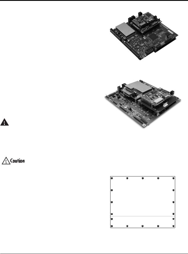
3.Carefully align the large connector (J1) on the bus adapter card with connector J6 on the 820i, J12 on the 720i, or J5 or J6 on the 920i CPU board. Press down to seat the bus adapter card in the CPU board connector.
4.Use the screws and lockwashers provided in the option kit to secure the other end of the option card to the threaded standoffs on the CPU board (see Figures 2-1 and 2-2).
5.Wire the card to the network as described in Section 2.2 on page 4.
6.Set DIP switch as described in Section 2.3 on page 4.
7.Use cable ties to secure loose cables inside the enclosure.
Figure 2-1. Option Installed on 820i CPU Board
Figure 2-2. Option Installed on 920i CPU Board
8.For indicator models that include a backplate, position the backplate over the enclosure and reinstall the backplate screws. For the 820i or 920i desktop and universal models, use the torque pattern shown in Figure 2-3 to prevent distorting the backplate gasket. Torque screws to 15 in-lb (1.7 N-m).
16 |
12 |
8 |
10 |
18 |
14 |
|
|
|
13 |
|
Torque backplate screws |
|
||
|
to 15 in-lb (1.7 N-m) |
|
||
5 |
|
|
|
6 |
3 |
|
|
|
2 |
1 |
|
|
|
4 |
17 |
9 |
7 |
11 |
15 |
Figure 2-3. 820i/920i Enclosure Backplate
2520/720i/820i/920i DeviceNet Installation and Programming Manual

9.Ensure no excess cable is left inside the enclosure and tighten cord grips.
10.Reconnect power to the indicator. The indicator automatically recognizes all installed option cards when the unit is powered on . No hardware - specific configuration is required to identify the newly-installed DeviceNet Interface to the system.
J1 |
GND |
LED Array |
TEST |
3.3V |
DIP Switch |
DeviceNet |
Module |
V+ |
CAN_H |
SHIELD |
CAN_L |
V– |
J2 |
Figure 2-4. Bus Adapter Card and DeviceNet Module
2.1.2Installing DeviceNet Option in the 520
Use the following procedure to install the DeviceNet Interface in the 520 indicator:
1. Disconnect indicator from power source.
Disconnect power before removing indicator enclosure cover.
Warning The 520 has no on/off switch. Before opening the unit, ensure the power cord is disconnected from the power outlet.
2.Place indicator on an antistatic work mat. Remove screws that hold the enclosure cover to the enclosure body.
Use a wrist strap to ground yourself and protect components from electrostatic discharge (ESD) when working inside the indicator enclosure.
3.Carefully align the large option card connector with connector J2 on the CPU board (see Figure 2-5). Press down to seat the option card in the CPU board connector.
Figure 2-5. Option Installed on 520 CPU Board
4.Use screws provided in the option kit to secure the other end of the option card to the threaded standoffs on the CPU board.
5.Install terminal block end of cable assembly to DeviceNet option card.
6.Remove existing cover plate.
7.Re-use kep nuts to secure DeviceNet cover plate to standoffs located on inside of enclosure backplate (see Figure 2-6).
8.Once cabling is complete, position the cover over the enclosure and reinstall the screws.
9.Reconnect power to the indicator.
Standoffs
Cover Plate
Figure 2-6. DeviceNet Cable Assembly
10.The indicator automatically recognizes all installed option cards when the unit is powered on . No hard ware - specific configuration is required to identify the newly-installed DeviceNet interface to the system.
Installation 3
Loading...