

Andrew Burrows Rocker shaft / Removal 13/02/16
Rocker shaft, removal
Remove the cylinder head cover.
See pages .
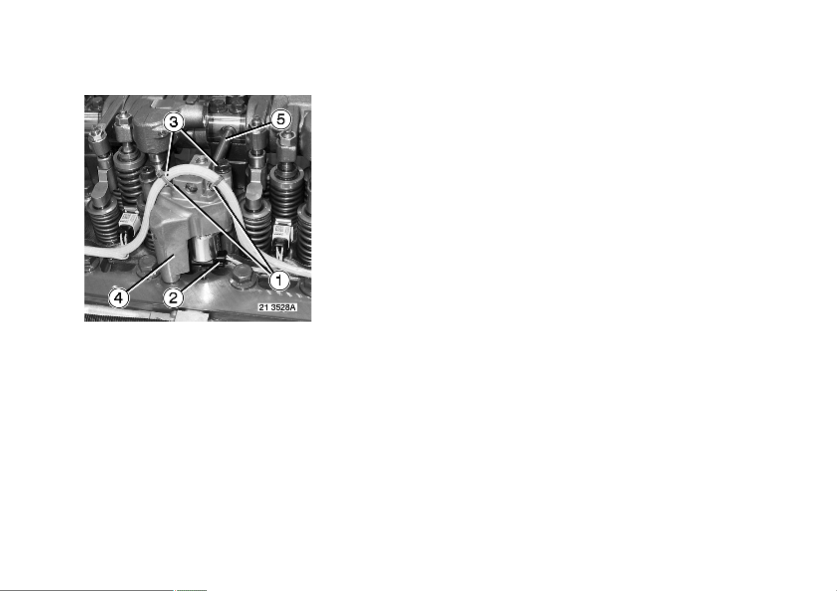
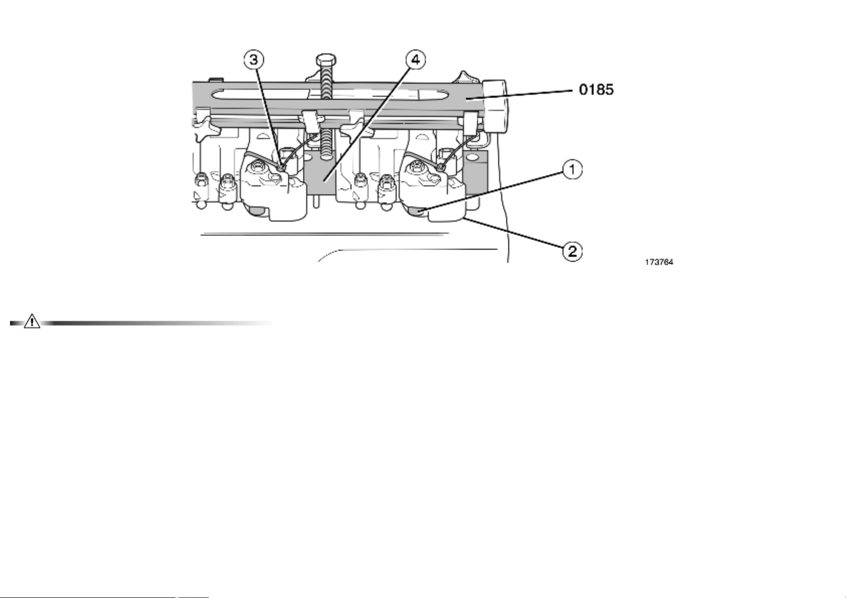
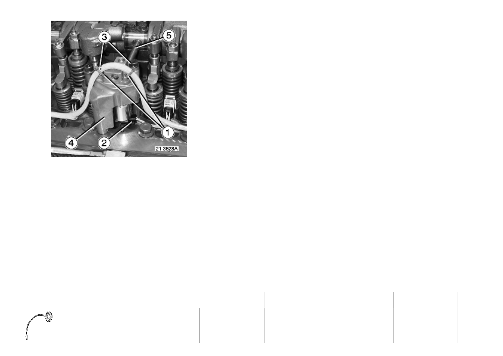
Remove brackets (1).
Depending on equipment
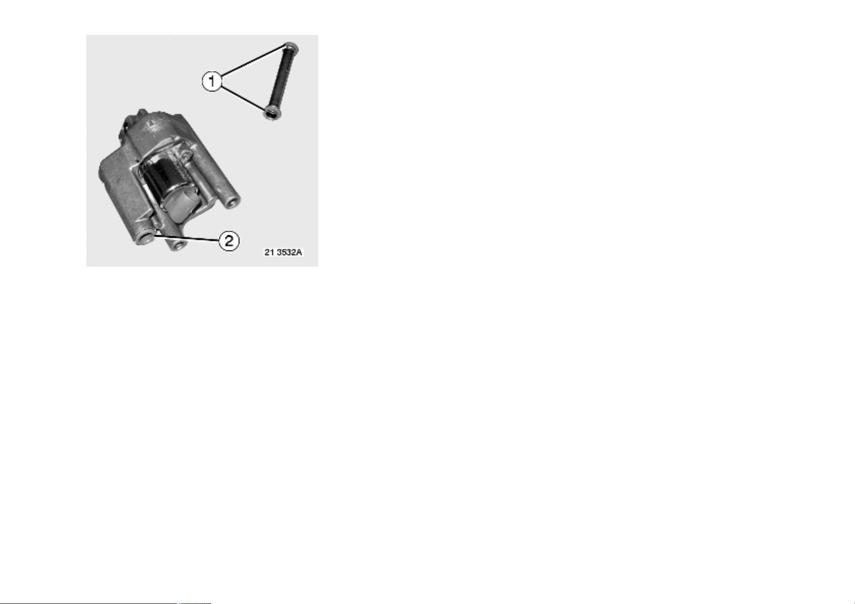
Unplug connector (2).
Remove bolts (3).
Remove control valve (4).
Remove tube (5).
1 / 7
Andrew Burrows Rocker shaft / Removal 13/02/16
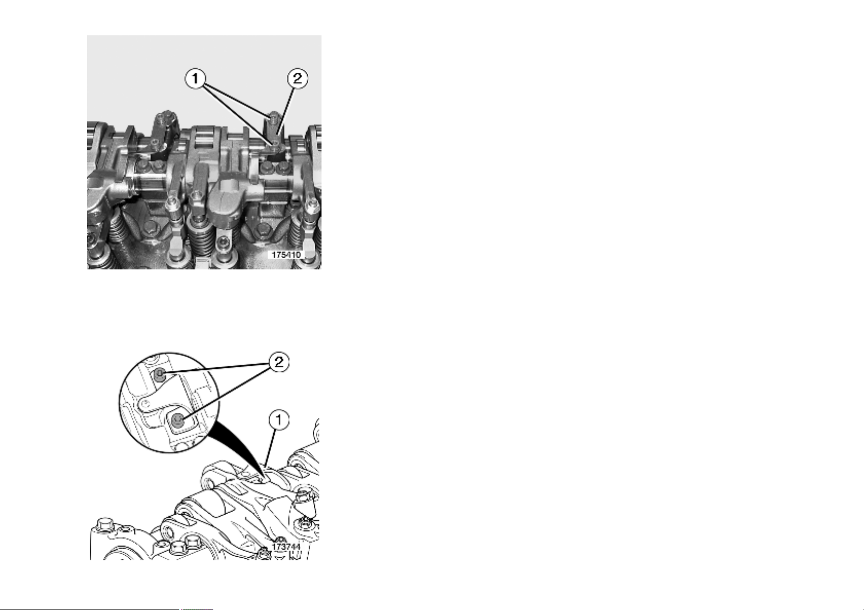
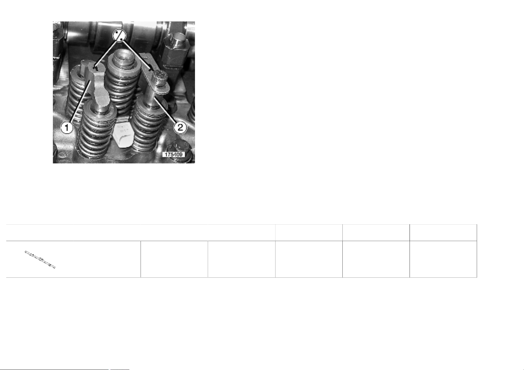
Engine equipped with "Optibrake"
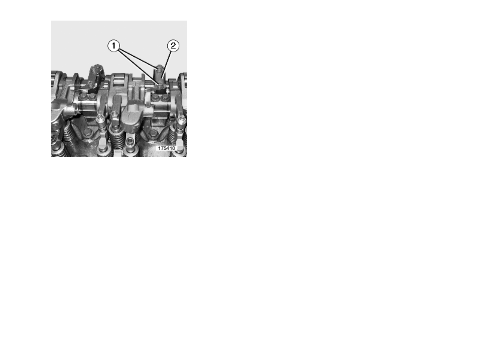
Remove bolts (1).
Remove elastic blades (2).
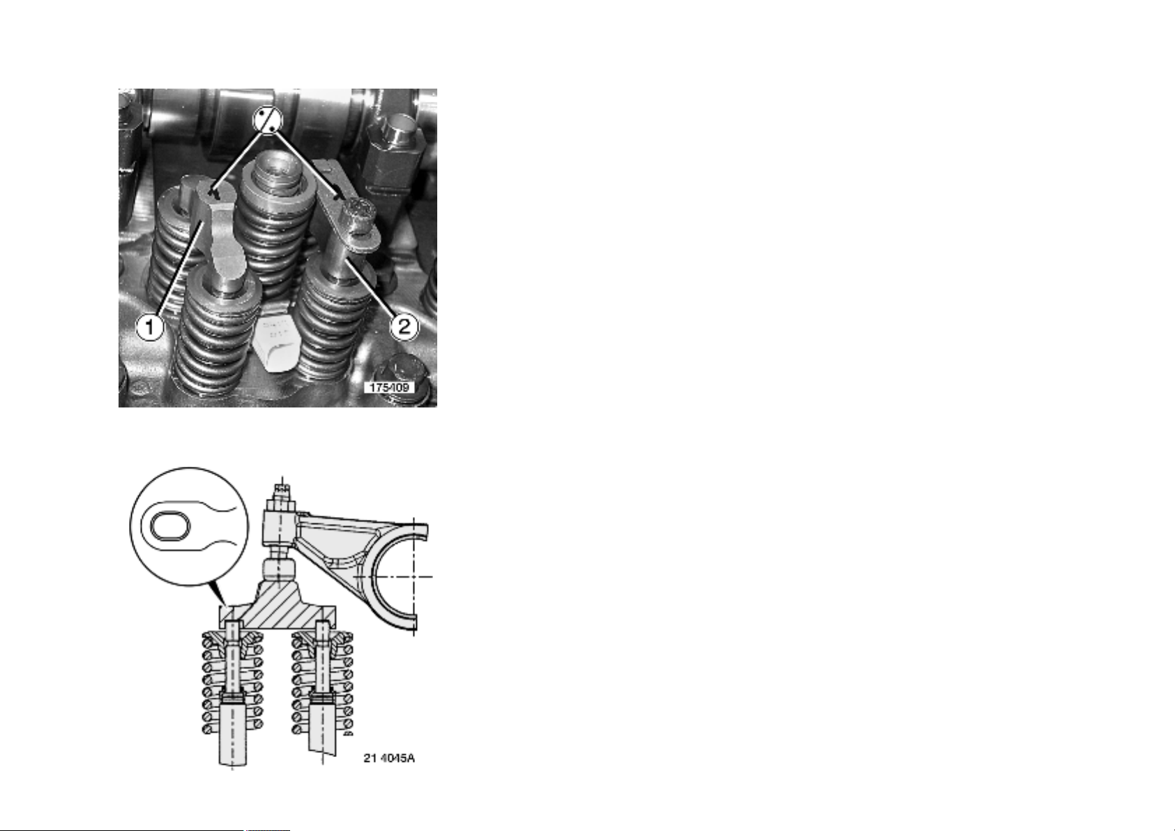
Engine equipped with "Optibrake +"
2 / 7
Andrew Burrows Rocker shaft / Removal 13/02/16
Remove bolts (2).
Remove elastic blades (1).
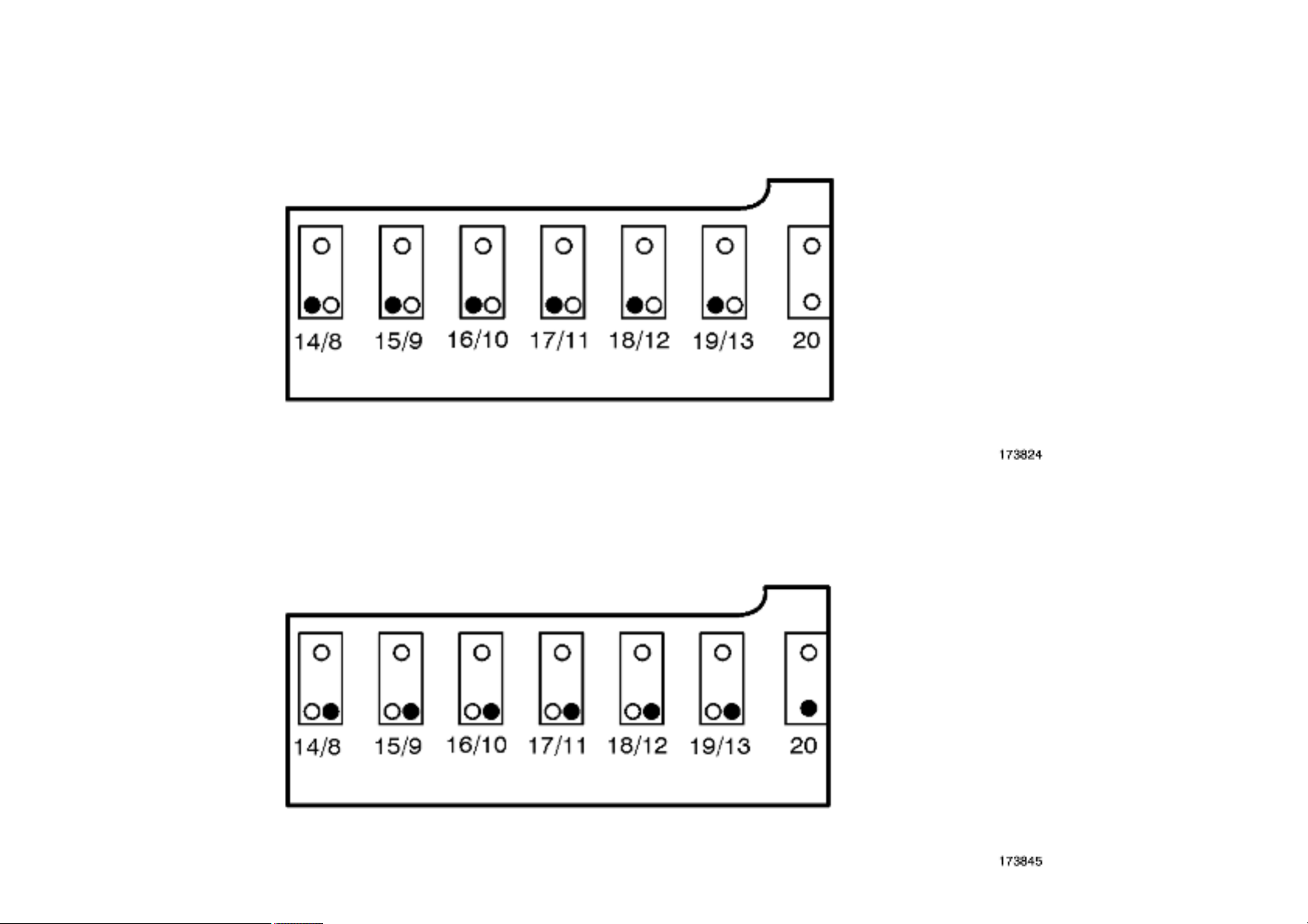
Remove bolts (14 › 19).
3 / 7
Andrew Burrows Rocker shaft / Removal 13/02/16
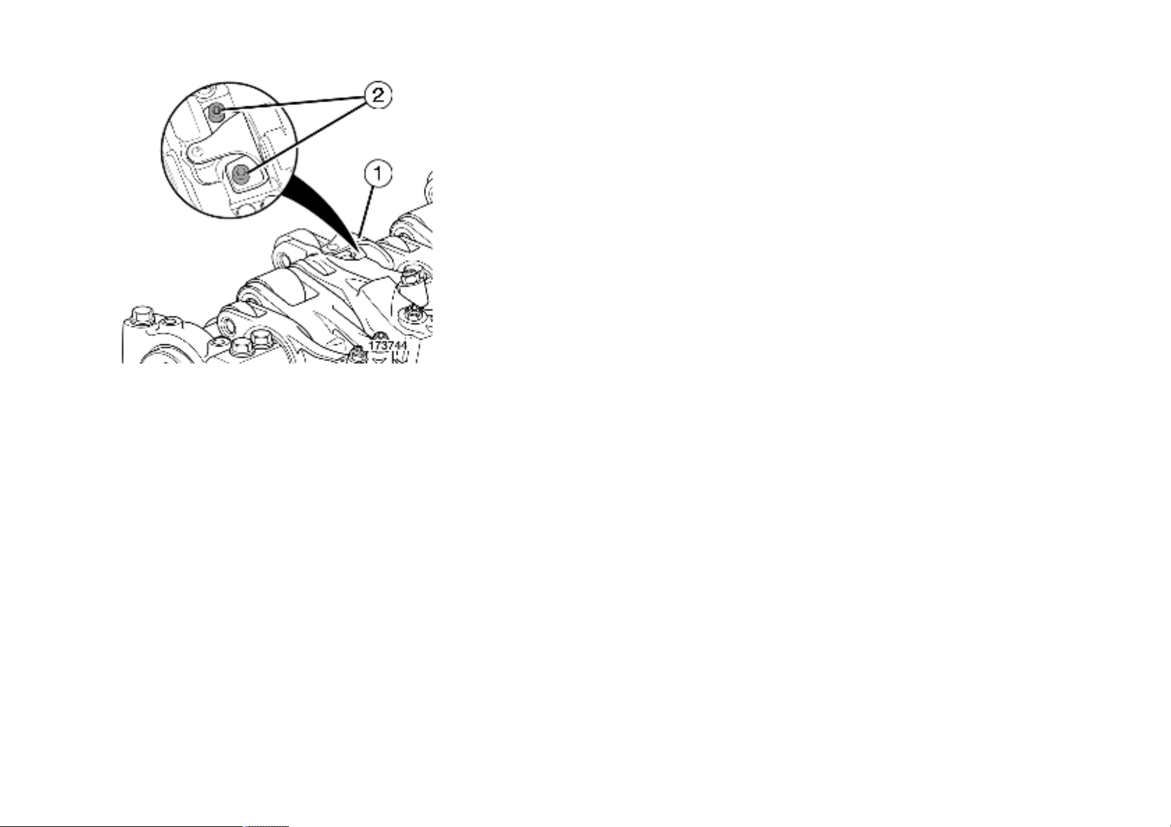
Loosen bolts (8 › 13 - 20) progressively so as to not distort the rocker shaft.
Remove bolts (8 › 13 - 20).
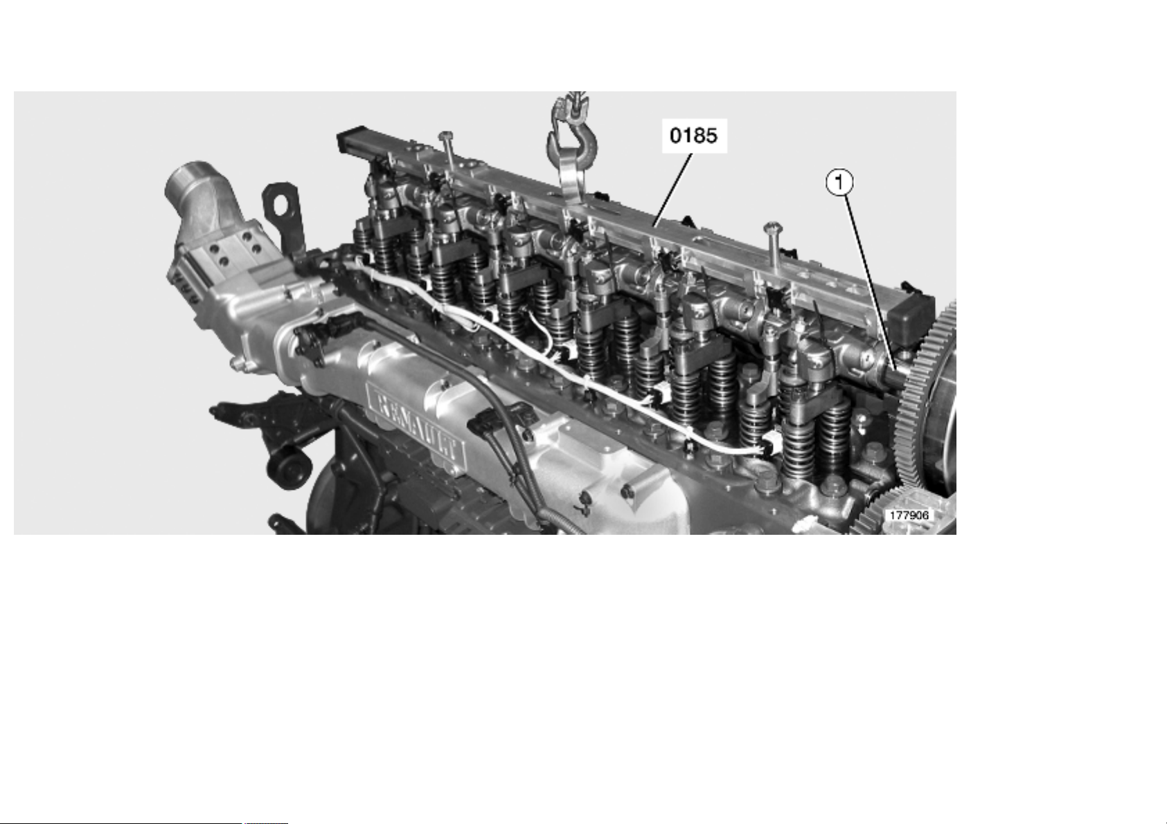
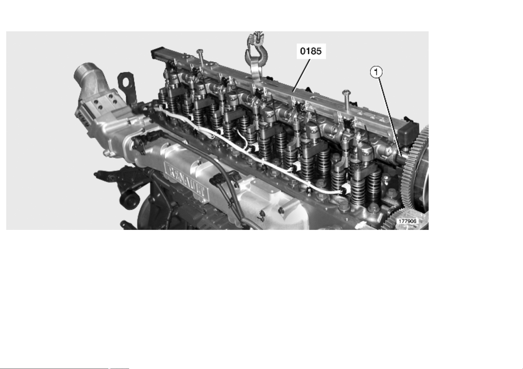
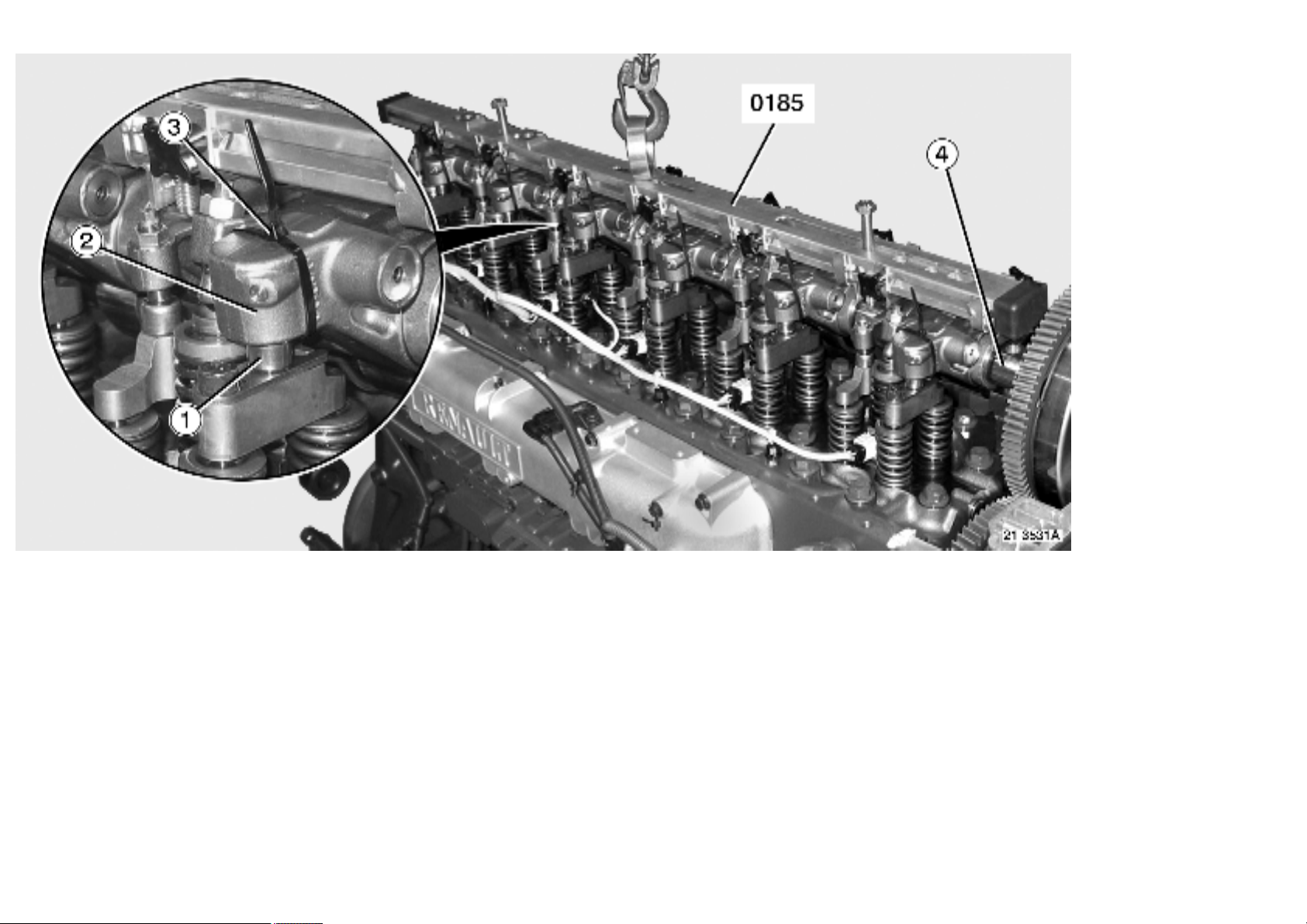
Mount tool 0185.
Remove the rocker assembly (1).
Use lifting tackle.
Engine equipped with "Optibrake"
4 / 7

Andrew Burrows Rocker shaft / Removal 13/02/16
Mount tool 0185.
For an engine equipped with "Optibrake", immobilize the piston (1) of each exhaust rocker arm (2) with a plastic clamp (3).
Blank off the openings in the cylinder head to prevent the ingress of foreign matter.
Remove the rocker assembly (4).
Use lifting tackle.
Engine equipped with "Optibrake +"
5 / 7
Andrew Burrows Rocker shaft / Removal 13/02/16
Mount tool 0185.
For an engine equipped with "Optibrake +", immobilize the piston (1) of each exhaust rocker arm (2) with a plastic clamp (3).
Blank off the openings in the cylinder head to prevent the ingress of foreign matter.
Remove the rocker assembly (4).
Use lifting tackle.
6 / 7
Andrew Burrows Rocker shaft / Removal 13/02/16
Mark.
Remove clips (1 - 2).
Tools
Specific tools
Illustration RENAULT
Designation Manufacturer's
TRUCKS part N°
7409990185 LIFTING TOOL (ROCKER
ARM ASSEMBLY)
Manufacturer's code N° Scale Qty
reference N°
2 1
7 / 7
Andrew Burrows Rocker shaft / Fitting 13/02/16
Rocker shaft, fitting
Fit yokes (1 - 2).
Line up the marks made upon removal.
1 / 12
Andrew Burrows Rocker shaft / Fitting 13/02/16
When fitting new yokes, line up the marks.
Oil all moving parts.
Use engine oil.
Fit the rocker shaft (1).
Use tool 0185.
Use lifting tackle.
Engine equipped with "Optibrake"
2 / 12
Andrew Burrows Rocker shaft / Fitting 13/02/16
Oil all moving parts.
Use engine oil.
Fit the rocker shaft (4).
Use tool 0185.
Use lifting tackle.
Cut clamps (3) to free the pistons (1) of rocker arms (2).
Withdraw tool 0185.
Engine equipped with "Optibrake +"
3 / 12

Andrew Burrows Rocker shaft / Fitting 13/02/16
Oil all moving parts.
Use engine oil.
Fit the rocker shaft (4).
Use tool 0185.
Use lifting tackle.
Cut clamps (3) to free the pistons (1) of rocker arms (2).
Withdraw tool 0185.
4 / 12

Andrew Burrows Rocker shaft / Fitting 13/02/16
Tighten the camshaft and rocker shaft securing bolts to torque, following the tightening sequence (see page ).
Use tool 9776.
Inspect the rocker arms.
See pages .
Adjust the valve rocker clearances.
See pages .
5 / 12
Andrew Burrows Rocker shaft / Fitting 13/02/16
Engine equipped with "Optibrake"
Fit elastic blades (2).
Fit bolts (1).
Tighten to torque.
See pages .
6 / 12
Andrew Burrows Rocker shaft / Fitting 13/02/16
Engine equipped with "Optibrake +"
Fit elastic blades (1).
Fit bolts (2).
Tighten to torque.
See pages .
7 / 12
Andrew Burrows Rocker shaft / Fitting 13/02/16
Clean the contact faces thoroughly.
Fit new seals (1 - 2).
For assembly of the rectangular section gasket.
See pages .
Clean the pipes.
8 / 12
Andrew Burrows Rocker shaft / Fitting 13/02/16
Fit pipe (5).
Fit control valve (4).
Fit bolts (3).
Tighten to torque.
See pages .
Depending on equipment
Plug in connector (2).
Fit new clamps (1).
Fit the rocker cover.
See pages .
Tools
Specific tools
Illustration RENAULT
Designation Manufacturer's
TRUCKS part N°
5000269776 INDICATOR DISC 1 1
reference N°
Manufacturer's code N° Scale Qty
9 / 12

Andrew Burrows Rocker shaft / Fitting 13/02/16
7409990185 LIFTING TOOL (ROCKER
ARM ASSEMBLY)
Rocker shaft and camshaft bearing caps, tightening torques
2 1
10 / 12
Andrew Burrows Rocker shaft / Fitting 13/02/16
Camshaft
Stage 1: bolts (1 › 7) 40±3 Nm
11 / 12
Andrew Burrows Rocker shaft / Fitting 13/02/16
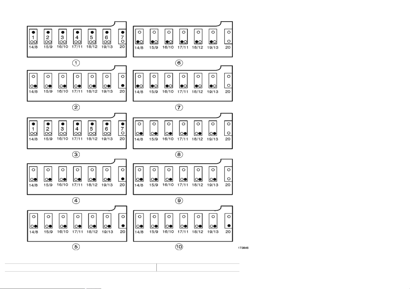
Stage 2: bolts (8 › 13 - 20) 60±5 Nm
For the 2th stage, tighten bolts gradually in the following order: 11 - 10 - 12 - 9 - 13 - 8 - 20, so that the rocker shaft can be lowered without being
damaged.
Stage 3: bolts (1 › 7) 90±5 °
Stage 4: bolts (8 › 13 - 20) Loosen the bolts
Rocker shaft
Stage 5: bolts (8 › 13 - 20) 60±5 Nm
For the 5th stage, tighten bolts gradually in the following order: 11 - 10 - 12 - 9 - 13 - 8 - 20, so that the rocker shaft can be lowered without being
damaged.
Stage 6: bolts (14 › 19) 40±3 Nm
Stage 7: bolts (14 › 19) 120±5 °
Stage 8: bolts (8 › 13) Loosen the bolts
Stage 9: bolts (8 › 13) 40±3 Nm
Stage 10: bolts (8 › 13 - 20) 120±5 °
12 / 12
Andrew Burrows Rocker arms / Inspection / testing 13/02/16
Rocker arms, inspection
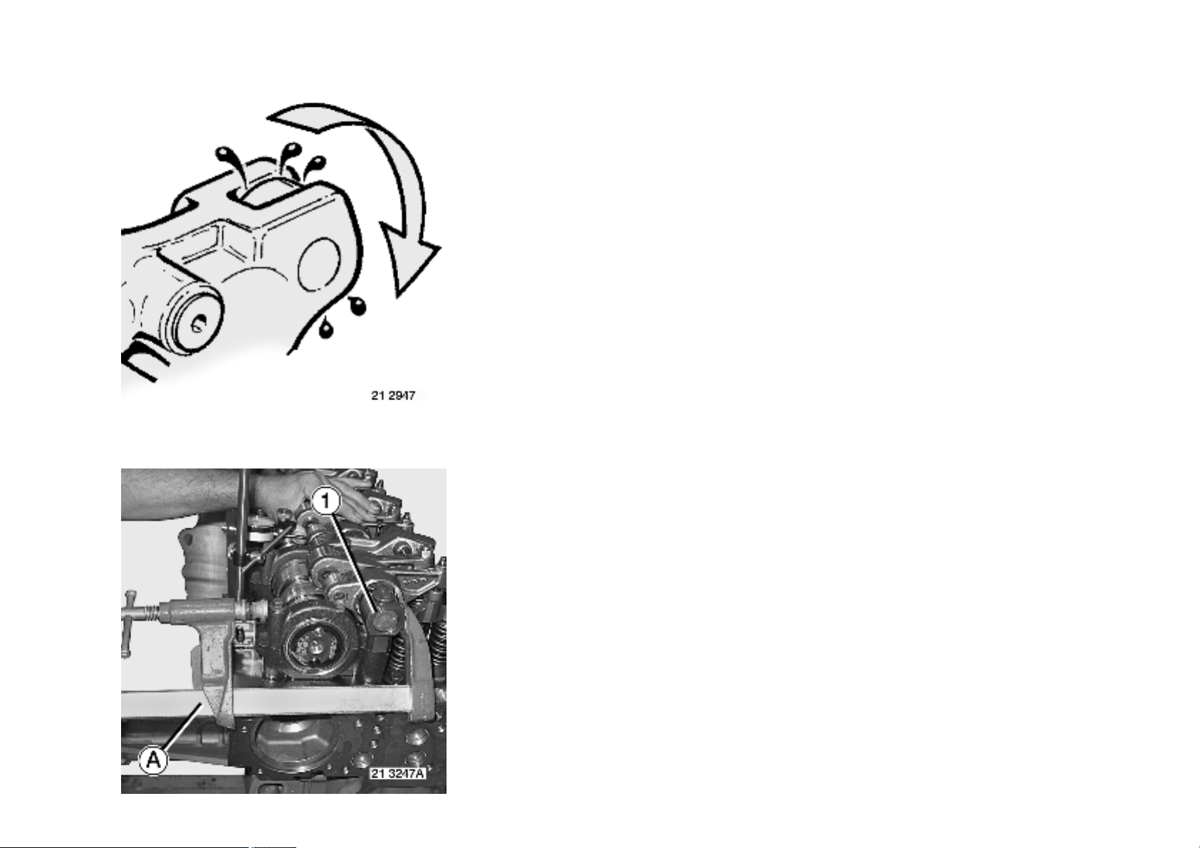
Turn the roller to eliminate the film of oil.
Check that the roller rotates freely.
1 / 6
Andrew Burrows Rocker arms / Inspection / testing 13/02/16
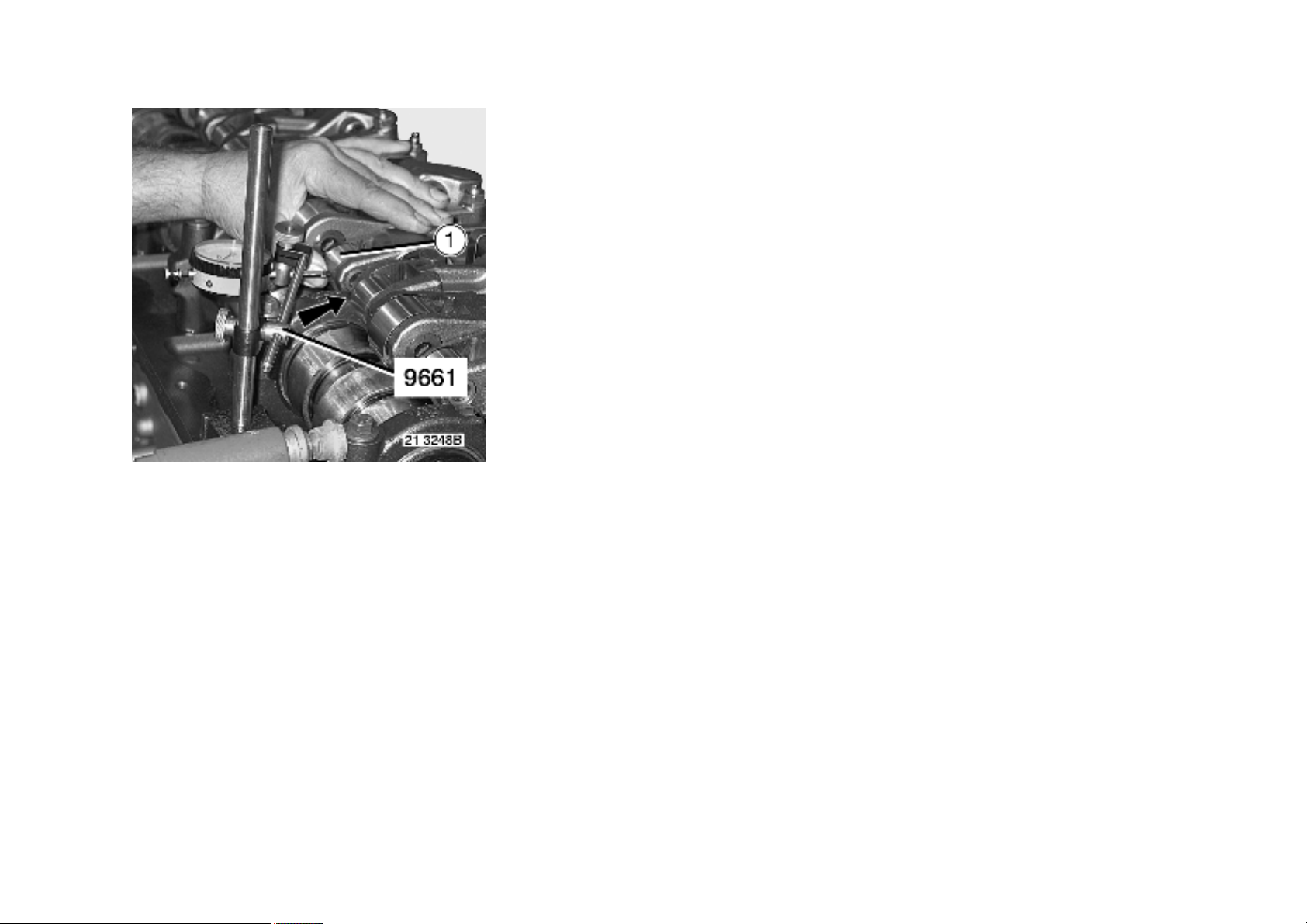
Checking the roller play
With the rocker shaft bolts loosened, using a screw clamp (A), immobilize rocker shaft (1).
Position the stylus of the dial gauge in the horizontal axis of the rocker arm roller.
Push roller (1) in the horizontal axis to eliminate the clearances.
Reset the dial gauge to zero.
Use tool 9661.
2 / 6
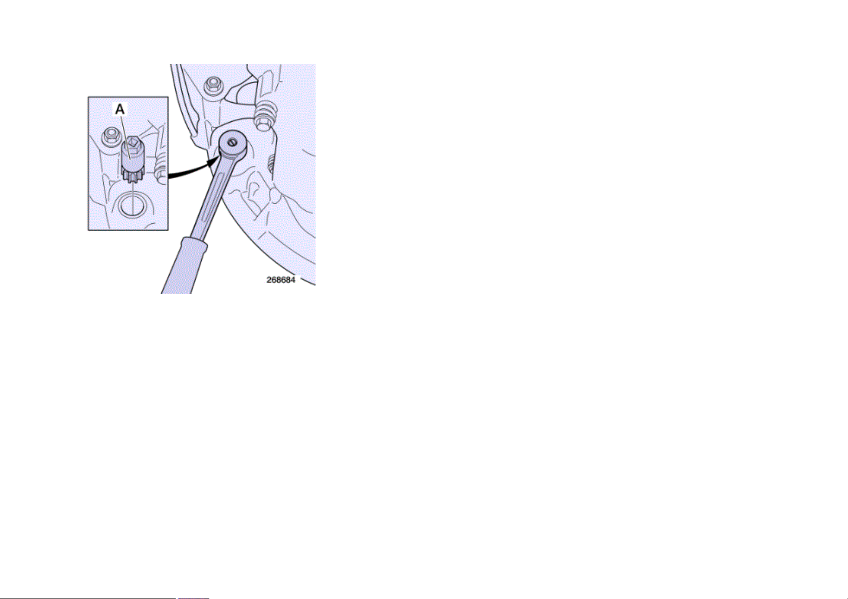
Andrew Burrows Rocker arms / Inspection / testing 13/02/16
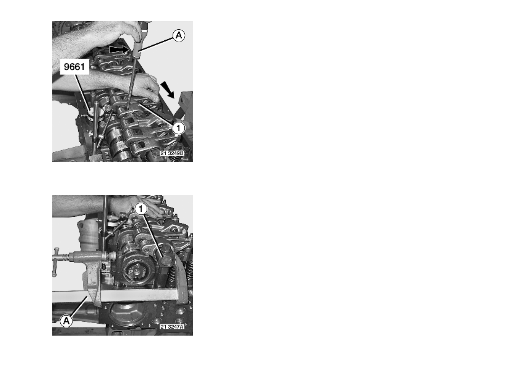
Using a screwdriver (A), measure the roller clearance while holding rocker arm (1) in a horizontal position.
For values, see "Technical data" chapter.
See pages .
Checking the rocker arm bearing clearance
3 / 6
Andrew Burrows Rocker arms / Inspection / testing 13/02/16
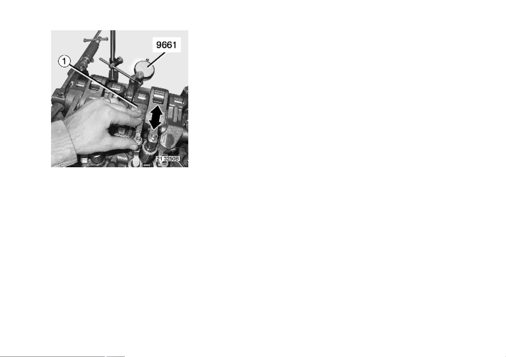
With the rocker shaft bolts loosened, using a screw clamp (A), immobilize rocker shaft (1).
Position the stylus of the dial gauge at the end of the rocker shaft in the horizontal axis.
Use tool 9661.
Reset the dial gauge to zero.
Push rocker arm (1) back in the opposite direction to measure the clearance.
See pages .
4 / 6
Andrew Burrows Rocker arms / Inspection / testing 13/02/16
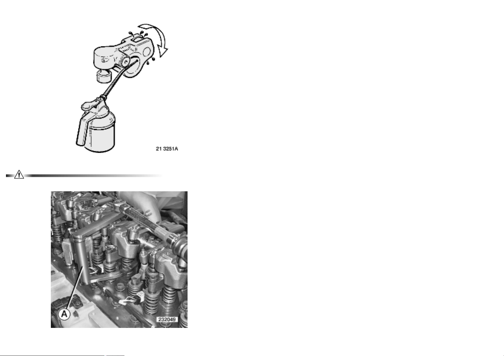
When replacing a rocker arm, use an oil can to squirt engine oil through the lubrication hole in the rocker arm to lubricate the roller shaft.
Upon removal, mark the position of the rocker arms on their shafts.
Check the torque of the injector flange attachment bolts without removing the rocker arm assembly.
5 / 6
Andrew Burrows Rocker arms / Inspection / testing 13/02/16
Use tool A.
A = 0162
Tighten to torque.
See page(s) .
This operation is to be performed at each valve adjustment maintenance.
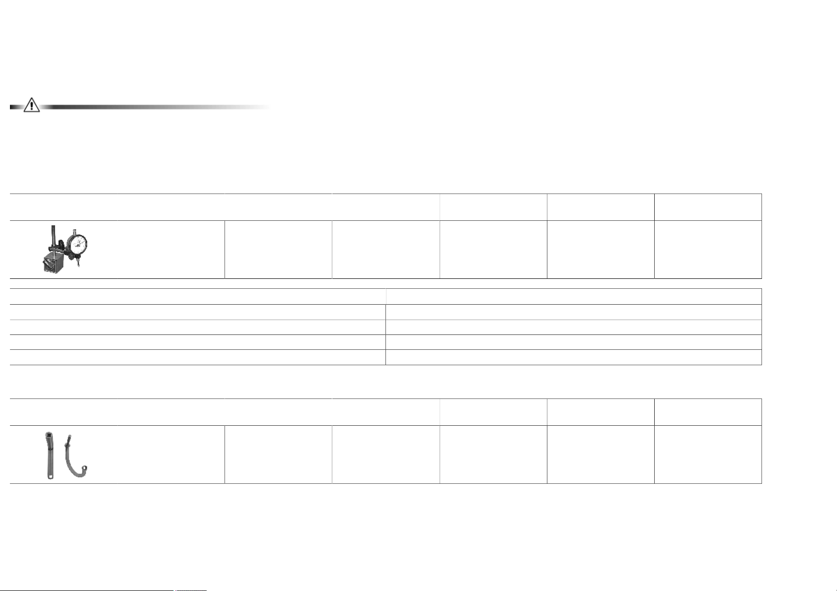
Tools
General purpose tools
Illustration RENAULT
Specific tools
Illustration RENAULT
Designation Manufacturer's
TRUCKS part N°
9661 MEASURING TOOL
(DIAL GAUGE AND
MAGNETIC FOOT)
AQ BROWN & SHARP ROCH
Designation Manufacturer's
TRUCKS part N°
7488840162 WRENCH 2 1
reference N°
AQ 1 1
reference N°
Manufacturer's code N° Scale Qty
13-15 avenue Georges de la Tour
BP 45
FRANCE
03 83 76 83 76 - 03 83 74 13 16 -
Manufacturer's code N° Scale Qty
6 / 6
Andrew Burrows Rocker arms / Adjustment 13/02/16
Rocker arms, adjustment
Remove the blanking plug.
Position the marks on the camshaft which indicate the number of the cylinder to adjust between the marks on the camshaft front bearing cap.
Use tool A.
A = 1380
Engine rotation: anti-clockwise, from the engine flywheel end.
Camshaft marks
1 / 24

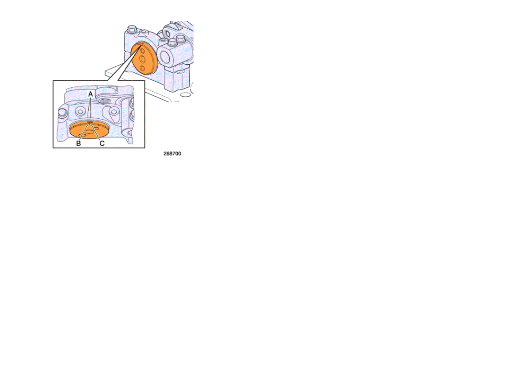
Andrew Burrows Rocker arms / Adjustment 13/02/16
Without "Optibrake" / "Optibrake +"
The marks (B) 1 - 5 - 3 - 6 - 2 - 4 correspond to the recommended inlet valve clearances , to the recommended exhaust valve clearances and to the
recommended pump injector pre-travel distances for each relative cylinder.
Mark (B) must be positioned in the centre of marks (A) when carrying out the adjustment.
For values, see "Technical data" chapter.
See pages .
2 / 24

Andrew Burrows Rocker arms / Adjustment 13/02/16
Engine equipped with "Optibrake"
The marks (B) 1 - 5 - 3 - 6 - 2 - 4 correspond to the recommended inlet valve clearances and to the recommended pump injector pre-travel distances for
each relative cylinder.
The marks (C) V1 - V5 - V3 - V6 - V2 - V4 correspond to the recommended exhaust valve clearances for each relative cylinder.
The marks (B) or (C) must be positioned between the marks (A) to make the correct adjustment.
For values, see "Technical data" chapter.
See pages .
3 / 24
Andrew Burrows Rocker arms / Adjustment 13/02/16
Engine equipped with "Optibrake +"
The marks (B) 1 - 5 - 3 - 6 - 2 - 4 correspond to the recommended inlet valve clearances and to the recommended pump injector pre-travel distances for
each relative cylinder.
The marks (C) E1 - E5 - E3 - E6 - E2 - E4 correspond to the recommended exhaust valve clearances for each relative cylinder.
The marks (B) or (C) must be positioned between the marks (A) to make the correct adjustment.
For values, see "Technical data" chapter.
See pages .
4 / 24
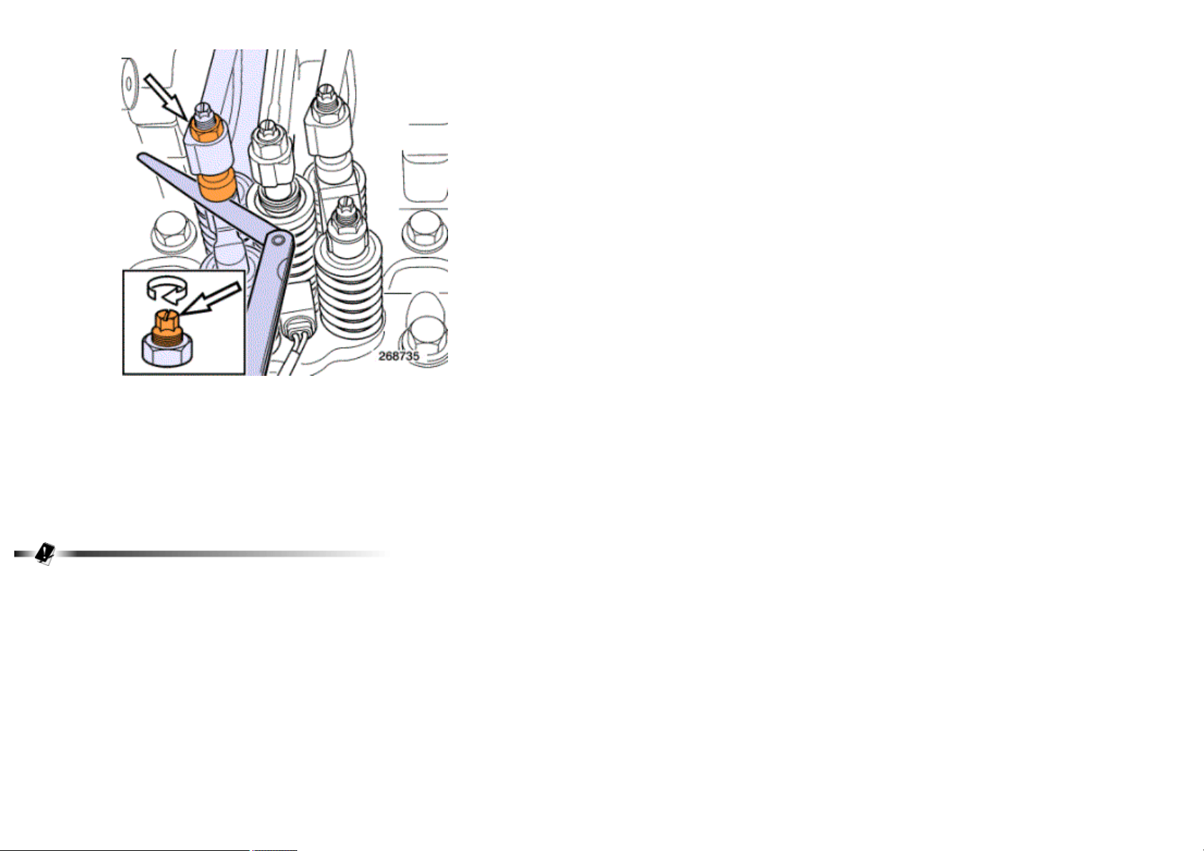
Andrew Burrows Rocker arms / Adjustment 13/02/16
Adjustment of inlet valves
Measure the valve clearances using feeler gauges.
See pages .
Loosen the locknut and the adjuster.
Adjust the clearance between the rocker arm and the valve yoke by means of screw.
Tighten the locknut to torque while holding the adjuster.
See pages .
Make a mark on the rocker arm when adjustment is finished.
Perform the same operation on all the other cylinders.
5 / 24
 Loading...