

REMKO ELT Series, ELT 3-2, ELT 3-2 E, ELT 10-6, ELT 10-6 E Operating And Installation Instructions
...
Operating and
installation instructions
REMKO ELT series
Electric heaters
ELT 3-2 (E), ELT 10-6 (E), ELT 18-9 (E)
This product is suitable only for well-insulated rooms or for occasional use.
Edition EN - Q03 Read the instructions prior to performing any task!


Contents
Safety notes 4
Unit description 4
Commissioning 5
Shutdown 6
Care and maintenance 7
Troubleshooting 7
Intended use 8
Customer service and guarantee
Environmental protection and recycling 8
Electrical wiring diagram
Exploded view of ELT 3-2 10
Spare parts list for ELT 3-2 10
Exploded view of ELT 10-6 11
Spare parts list for ELT 10-6 11
Exploded view of ELT 18-9 12
Spare parts list for ELT 18-9 13
Maintenance protocol 14
Technical data 15
9
8
Carefully read this operating manual prior to commissioning / using
the units!
This operating manual is a translation of the German original.
These instructions are an integral part of the unit and must always be
kept in the vicinity of the installation location or on the unit itself.
Subject to modifications; no liability accepted for errors or misprints!
3

REMKO ELT series
Safety notes Unit description
Always observe the respective local building code and fire prevention
guidelines as well as the guidelines of the accident prevention and
insurance associations when using the units.
The units have been subjected
to extensive material, functional
and quality inspections prior to
delivery. However, dangers can
arise from the units if they are used
improperly or not as intended by
untrained personnel!
Please observe the following notes:
■
The personnel tasked with
operating the units must check
the units for visible defects on
the operating and safety devices
as well as the presence and
function of the protective devices
prior to starting work
Inform the supervisor if defects
are discovered!
■
In the event of defects that
endanger the operational safety
of the unit, operation must be
discontinued immediately
■
Observe the respective local
regulations and the relevant
electrical safety measures when
using the units
■
Maintain safety distances to
combustible materials
■
An unobstructed air inlet and air
outlet must be guaranteed at all
times
■
Never insert foreign objects into
the units
■
The units must not be covered
during operation
■
Safety devices must not be
bypassed or disabled
■ The units must not be operated
in the vicinity of bathtubs,
showers, swimming pools etc.
■
The units must not be operated
directly below a wall socket
■
The units must not be exposed
to direct jets of water
e.g. pressure washers etc.
■ Never allow water to enter the
units
■
The units must not be installed
or operated in potentially
flammable or explosive
environments
■
The units must not be installed
or operated in atmospheres
containing oil, sulphur or salt
■ All electrical cables for the
units must be protected against
damage, even damage caused
by animals
The units are portable electric
heating units for industrial
applications.
The units are operated exclusively
with electric power and have been
designed in such a way that they
can be used fully automatically,
universally and in a straightforward
manner.
The units are equipped with
specially enclosed electric heating
resistors, low noise and lowmaintenance axial fans, safety and
aftercooler thermostats, a room
thermostat socket and power cable
with protective contact plug.
The units conform to the
fundamental health and safety
requirements of the appropriate
EU stipulations.
The units are dependable and offer
ease of operation.
The units may be used among
other things for the following:
■
Drying newly completed
buildings
■
Spot heating outdoor
workspaces or fire-proof
manufacturing facilities and
halls
■
Continuous or temporary room
heating
■
The air outlet must not be
constricted or equipped with
pipe or hose lines
4
■
The units must be set up in
a stable, horizontal position
CAUTION
Safety devices must not be
bypassed or disabled.
■
De-icing machines, vehicles and
non-combustible warehoused
goods while adhering to the
relevant safety distances

Commissioning
Operating sequence
The units can be used in the
respective operating modes for
air heating and air circulation
purposes (not ELT 3-2).
The units ELT 3-2 can be operated
exclusively in 2 heating stages
(2.2 or 3.2 kW).
They have a 3-stage operating
switch with the functions: Heat (I)
/ Off (0) / Heat (II).
The units ELT 10-6 and ELT 18-9
can be operated with three heating
settings and one fan setting.
They have a 5-stage operating
switch with the functions:
Off (0) / Fan (1) / Heat (2-4).
All units can be equipped with
a plug-in ready room thermostat
(accessory) to ensure that the
room temperature is constant.
Once the desired temperature
has been reached, the thermostat
switches the heating operation
off. If the room temperature falls
below the set temperature, the
thermostat starts up the heating
operation again.
!
CAUTION
After switching off the units
via the operating switch or
the room thermostats, the
supply air fan runs to cool the
heating resistors for a certain
time and then switches off
automatically.
NOTE
For optimum operation the
units should not be operated
above an ambient temperature
of 25 °C.
One person, who has been
adequately trained in the handling
of the units, should be tasked with
the operation and monitoring of
the units.
The units must be in the intended
horizontal position on their
supports at all times during
operation.
The units are equipped with the
following operating switches:
Operating switch ELT 3-2
Heating 1st stage; 2.2 kW
Off
Heating 2nd stage; 3.2 kW
Operating switch
ELT 10-6 and ELT 18-9
Off
Fan
1st heating stage
2nd heating stage
3rd heating stage
1. Check the customer’s mains
voltage and ensure sufficient
fuse protection for the unit type
in use.
Power supplies:
ELT 3-2 230V/1~/50 Hz
ELT 10-6 400/3~N/50 Hz
ELT 18-9 400/3~N/50 Hz
2. Move the operating switch to
the "0" (Off) position.
ELT 3-2
ELT 10-6 / 18-9
3. Connect the unit's power plug
to a properly installed mains
socket.
ELT 3-2
ELT 10-6
ELT 18-9
NOTE
The electrical connection for
the units must be made at
a separate feed point with
a residual current device in
accordance with VDE 0100,
Section 55.
CAUTION
Extensions to the connection
cable must only be conducted
by authorised specialist
electricians, taking into
consideration the unit capacity,
cable length and local use.
s
s
s
5

REMKO ELT series
s
s
s
Shutdown
Operating settings
The operating settings can be
selected via a switch or a cam
switch.
However, a room thermostat is
always required for operation.
ELT 3-2
1st stage
2nd stage
ELT 10-6 and ELT 18-9
1st stage
Fan
Only the supply air fan operates in
this setting.
Thermostatic regulation and
heating operation are not possible
in this operating mode.
2nd stage
3rd stage
Heating with room thermostat
(Accessories)
The units operate fully
automatically and according to the
respective room temperature.
1. Pull out the strapping plug [2].
2. Connect the plug [3] of the
room thermostat [4] with the
thermostat socket [1] on the
unit.
1
3
3. Place the room thermostat [4]
at a suitable location in the
room.
The thermostat sensor must not
be located directly in the warm
air flow and must not be placed
directly on the cold floor.
1. Move the operating switch to
the “0” position.
ELT 3-2
The supply air fan runs on to cool
the units and only switches off
after the cooling down phase is
complete.
The fan can switch on and run
several times before the final
shutdown.
2. If the units are inactive for long
periods, disconnect them from
the mains power supply.
ELT 10-6 / 18-9
ELT 3-2
Move the operating switch to the
desired position 1.
ELT 10-6 / 18-9
!
CAUTION
There is no separate ventilation
function for this ELT 3-2.
4. Set the desired room
temperature on the room
thermostat [4].
4
5. Select the desired power
position on the respective
operating switch.
ELT 10-6
ELT 18-9
CAUTION
Never interrupt the power
supply prior to the completion
of the follow-up cooling phase.
There is no warranty claim
for damage to the units from
overheating.
6

Care and maintenance
Troubleshooting
NOTE
Regular care and maintenance,
at the latest after every
heating period, is the basic
requirement for a long service
life and malfunction-free
operation of the units.
■
Observe the regular care and
maintenance intervals
CAUTION
Before undertaking any work
on the units, the power plug
must be removed from the
mains socket.
■
In accordance with the
operating conditions, the units
must, if necessary, be checked
at least yearly by a specialist
to ensure that they are in
a condition that is safe to use
■
Keep the units free of dust and
other debris
■
Only clean the units with a dry
or lightly moistened cloth
■
Never subject to direct jets of
water.
e.g. pressure washers etc.
■
Never use abrasive or solvent-
based cleaners
■
Use only suitable cleaners, even
for heavy contamination
■
Check the inlet and outlet grille
for contamination on a regular
basis
■
Check the safety equipment
and protective devices on
a regular basis
■
Be careful not to damage the
probe or capillary tube of the
temperature limiter when
removing or mounting the
protective outlet grille
NOTE
Setting and maintenance
work may only be carried out
by authorised and qualified
technicians.
CAUTION
An electrical safety check must
be carried out in accordance
with VDE 0701 after any work
on the units.
NOTE
Replace defective or damaged
parts immediately and
exclusively with original spare
parts.
Checking
The strapping plug supplied with
the device is used for maintenance
or testing according to VDE 0701.
Follow the steps below to check.
1. Connect the supplied strapping
plug [2] to the thermostat
socket [1] on the unit.
1
The unit (fan) does not start.
1.
Check the mains fuses on site.
2. Check the power plug.
3. Check the operating switch.
4. Check that the fan can move
freely.
The unit does not heat up.
1.
Check the operating switch.
2. Check that the contactor is
functioning correctly.
3.
Check that the temperature
limiter or capillary tube are
functioning correctly and check
for damage.
4.
Check whether the thermostat
or strapping plug are plugged
in.
5.
In case of unit operation
with a room thermostat, set
the thermostat to a value
that is higher than the room
temperature.
If all of the functional checks
have been carried out without
any findings, please contact an
authorised service station.
2
2. Check the device.
3. Remove the strapping plug
7

REMKO ELT series
Intended use
Customer service and
Guarantee
Environmental
protection and
recycling
The units (not ELT 3-2) are
designed exclusively for heating
and ventilation purposes in
industrial or commercial use (no
living space heating) on the basis
of their structural design and
equipment.
Any different or additional use is a
non-intended use.
The manufacturer/supplier
assumes no liability for damages
arising from non-intended use.
The units must only be operated
by appropriately instructed
personnel.
With non-observance of the
manufacturer's specifications, the
respective local legal requirements
or after arbitrary alterations to the
units, the manufacturer shall not
be liable for resulting damages.
NOTE
Operation other than the types
listed in this operating manual
is prohibited.
With non-observance, any
manufacturer liability or
guarantee claims are voided.
As a prerequisite for any guarantee
claims to be considered, it is
essential that the ordering
party or its representative
complete and return the
“certificate of guarantee” to
REMKO GmbH & Co. KG at the
time when the units are purchased
and commissioned.
The units are tested several times
to verify their correct function.
However, if malfunctions should
arise that cannot be remedied by
the operator with the assistance of
the troubleshooting section, please
contact your specialist dealer or
contractual partner.
NOTE
Setting and maintenance
work may only be carried out
by authorised and qualified
technicians.
Disposing of packaging
When disposing of packaging
material, please consider our
environment.
Our units are carefully packed
and delivered in sturdy transport
packaging made from cardboard
and polystyrene.
The packaging materials are
environmentally-friendly and can
be recycled.
By recycling packaging materials,
you make a valuable contribution
to the reduction of waste and
conservation of raw materials.
Therefore, only dispose of
packaging material at appropriate
collection points.
Disposal of the old unit
The manufacturing process for
the units is subject to continuous
quality control.
Only high-grade materials are
processed, the majority of which
are recyclable. You also contribute
to environmental protection
by ensuring that your used
equipment is only disposed of in
an environment friendly manner.
CAUTION
Copyright
The redistribution, even
in part, or the use of this
documentation for purposes
other than intended is
strictly prohibited without
the written authorisation of
REMKO GmbH & Co. KG
8
Therefore, only bring the old
unit to an authorised recycling
business or to an appropriate
collection point.
.

Electrical wiring diagram
ELT 3-2; 2-stage ELT 10-6
230V/1~/50Hz
L1NPE
4
KL
6
5
4321
M
1~
6
5
L1 L2 L3 N PE
L1 L2 L3 N
KL
1 2 3 4 5
STB
TB
RT
1
2
3
HW 2
HW 1
1,0 kW
2,2 kW
B
9 7
6 4
1
2
RT
3
Legend:
= Auxiliary relay
HR
HW = Heating resistor
K1 = Contactor 1
HR
TB
M
A2
1A
4B
I
5B
6B
A
S
2A
3A
II
A1
1~
K1
NK
x
H
M
1
V1
L1
V2
L2
V3
V4
L3
V5
V6
HW
1-6
NK
08.2018
S
08.2018
ELT 18-9
L1 L2 L3 N PE
RT
1
3
2
L1 L2 L3 N
KL
1 2 3 4 5
STB
TB
NK
K2 = Contactor 2
KL = Connection terminal strip
M = Fan motor
NK = Aftercooler thermostat
RT = Thermostat socket
S = Operating switch
STB = Temperature limiter with
probe
= Temperature limiter
TB
We reserve the right to modify the dimensions and design as part of the ongoing technical development process.
A2
A1
HW
1-9
M
1~
A2
K1K2
A1
H
x
M
1
L1
V1
V2
L2
V3
V4
L3
V5
V6
S
08.2018
9
REMKO ELT series
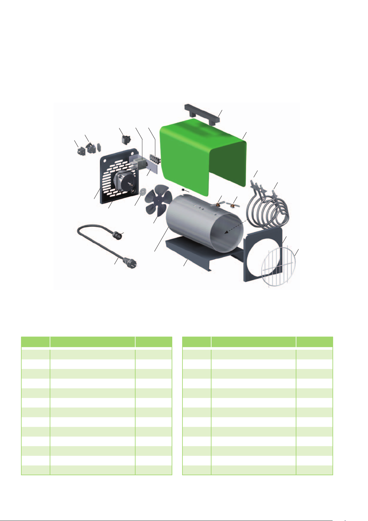
Exploded view of ELT 3-2 (E)
20 21
19
18
17
23
14
13
12
24
1
2
6
7
3
4
16
15
11
8
9
5
10
Spare parts list
No. Designation EDP no. No. Designation EDP no.
1 Transport handle 1101142 13 Fan motor 1103820
2 Exterior cladding ELT 3-2 1103905 14 Back wall 1103913
2a Exterior cladding ELT 3-2 E 1103940 15 Mains cable with plug 1103901
3 Aftercooler thermostat 1104065 16 Strain relief 1101267
4 Temperature limiter 1101161 17 Strapping plug 1101019
5 Inner casing 1103907 18 Thermostat socket, cpl. 1101018
6 Heating resistor 1.0 kW 1103908 19 Operating switch cpl. 1101188
7 Heating resistor 2.2 kW 1103909 20 Contactor 1108038
8 Front wall 1103910 21 Terminal block 1101366
9 Protective outlet grille 1103803 23 Mounting plate 1101067
10 Floor panel 1103911 24 Grommet, small 1101304
11 Fan blade 1103902
12 Drive clutch 1108455
When ordering spare parts, in addition to the EDP no. please always also quote the unit number and unit type (see name plate)!
Not shown
Thermostat plug 1101020
10
We reserve the right to modify the dimensions and design as part of the ongoing technical development process.

Exploded view of ELT 10-6 (E)
1
2
16
15
19
24
13
12
18
Spare parts list
25
14
17
10
11
21
20
22
23
5
3
4
9
8
6
7
8
No. Designation EDP no. No. Designation EDP no.
1 Transport handle 1101142 13 Back wall 1103954
2 Exterior cladding ELT 10-6 1107910 14 Strain relief 1107944
2a Exterior cladding ELT 10-6 E 1107909 15 Strapping plug 1101019
3 Inner casing 1103951 16 Thermostat socket, cpl. 1101018
4 Protective outlet grille 1103952 17 Operating switch cpl. 1107993
5 Front wall 1103953 18 Terminal block 5er 1107952
6 Floor panel 1107913 19 Contactor 1101096
7 Support 1107914 20 Grommet 1101304
8 Temperature limiter
9 Protective hose 1107915 22 Temperature limiter 1101161
10 Fan blade 1103950 23 Aftercooler thermostat 1104065
11 Drive clutch 1103956 24 Mounting angle 1101031
12 Fan motor 230 V 1101254 25 Mains cable with plug 1101026
When ordering spare parts, in addition to the EDP no. please always also quote the unit number and unit type (see name plate)!
We reserve the right to modify the dimensions and design as part of the ongoing technical development process.
with probe
1107960 21 Heating resistor 1103955
11

REMKO ELT series
Exploded view of ELT 18-9 (E)
18
1
2
17
16
14
26
15
19
13
10
12
11
20
8
21
21
22
24
23
9
7
3
8
4
25
5
6
12
We reserve the right to modify the dimensions and design as part of the ongoing technical development process.

Spare parts list
No. Designation EDP no.
1 Transport handle 1101142
2 Exterior cladding ELT 18-9 1107920
2a Exterior cladding ELT 18-9 E 1107919
3 Interior cladding with blow-out cone 1107953
4 Seal for blow-out cone 1107954
5 Protective outlet grille 1101353
6 Front wall 1107921
7 Floor panel 1107950
8 Temperature limiter
9 Support 1107922
10 Protective hose 1107915
11 Fan blade 1101153
12 Drive clutch 1103956
13 Fan motor 230 V 1101254
with probe
1107960
14 Back wall 1107923
15 Strain relief 1107961
16 Thermostat socket, cpl. 1101018
17 Strapping plug 1101019
18 Protective intake grille 1107947
19 Grommet 1101304
20 Operating switch cpl. 1107993
21 Contactor 1101096
22 Terminal block 5er 1107952
23 Aftercooler thermostat 1104065
24 Temperature limiter 1101161
25 Heating resistor 1107998
26 Mains cable with plug 1107962
Not shown
Thermostat plug 1101020
When ordering spare parts, in addition to the EDP no. please always also quote the unit number and unit type (see name plate)!
13

REMKO ELT series
Maintenance protocol
Unit type: .................................. Unit number: ...................................
1 2 3 4 5 6 7 8 9 10 11 12 13 14 15 16 17 18 19 20
Unit cleaned - outside -
Unit cleaned - inside -
Fan blade cleaned
Protection grid cleaned
Safety equipment checked
Safety devices checked
Unit checked for damage
All fastening screws checked
Electrical safety check
Test run
✍
Comments:......................................................................................................................................................
............................................................................................................................................................................
............................................................................................................................................................................
1. Date: ..............
..............................
Signature
6. Date: ..............
..............................
Signature
11. Date: ............
..............................
Signature
2. Date: ..............
..............................
Signature
7. Date: ..............
..............................
Signature
12. Date: ............
..............................
Signature
3. Date: ..............
..............................
Signature
8. Date: ..............
..............................
Signature
13. Date: ............
..............................
Signature
4. Date: ..............
..............................
Signature
9. Date: ..............
..............................
Signature
14. Date: ............
..............................
Signature
5. Date: ..............
..............................
Signature
10. Date: ............
..............................
Signature
15. Date: ............
..............................
Signature
16. Date: ............
..............................
Signature
Unit to be maintained only by authorised specialists in accordance with the statutory regulations.
14
17. Date: ............
..............................
Signature
18. Date: ............
..............................
Signature
19. Date: ............
..............................
Signature
20. Date: ............
..............................
Signature

Technical data
Series
Nominal heating capacity P
Minimum heating power P
Maximum continuous
heating power
Symbol
nom
min
P
max,c
Unit ELT 3-2 (E) ELT 10-6 (E) ELT 18-9 (E)
kW 3.2 10.5 18
kW 2.2 3.5 6
kW 3.2 10.5 18
Switchable heating capacity kW 2.2 or 3.2 3 x 3.5 3 x 6
3
Air volume m
/h 350 750 1,000
Power supply V/Hz 230/1~/50 400/3~N / 50 400/3~N / 50
Max. rated current A 13.9 14.9 27.5
Max. power consumption kW 2.25 / 3.25 10.65 18.2
Auxiliary current consumption at
nominal heating power
Auxiliary current consumption at
minimum heating power
Auxiliary current consumption in
standby condition
Electrical protection (provided by the
customer - slow)
el
max
el
min
el
SB
kW 3.250 10.650 18.150
kW 2.250 3.650 6.150
kW 0.000 0.000 0.000
A 16 16 32
Sound pressure level L
1m 1) dB (A) 46 53 57
pA
Dimensions: L/W/H mm 400/200/335 675/300/455 740/335/500
Type of room temperature control with elecrical room temperature control (external)
Weight kg 6.8 20.0 27.4
EDP no.: 114155 (114165) 114255 (114265) 114305 (114315)
1) Noise level measurement DIN 45635 - 01 - KL 3
( ) INOX design
We reserve the right to modify the dimensions and design as part of the ongoing technical development process.
15

REMKO QUALITY WITH SYSTEMS
Air-Conditioning | Heating | New Energies
REMKO GmbH & Co. KG
Klima- und Wärmetechnik
Im Seelenkamp 12
32791 Lage
Telephone +49 (0) 5232 606-0
Telefax +49 (0) 5232 606-260
E-mail info@remko.de
URL www.remko.de
Hotline within Germany
+49 (0) 5232 6 06-0
Hotline International
+49 (0) 5232 606-130
We reserve the right to make technical changes, and provide no guarantee as to the accuracy of this data!
 Loading...