

Page 1
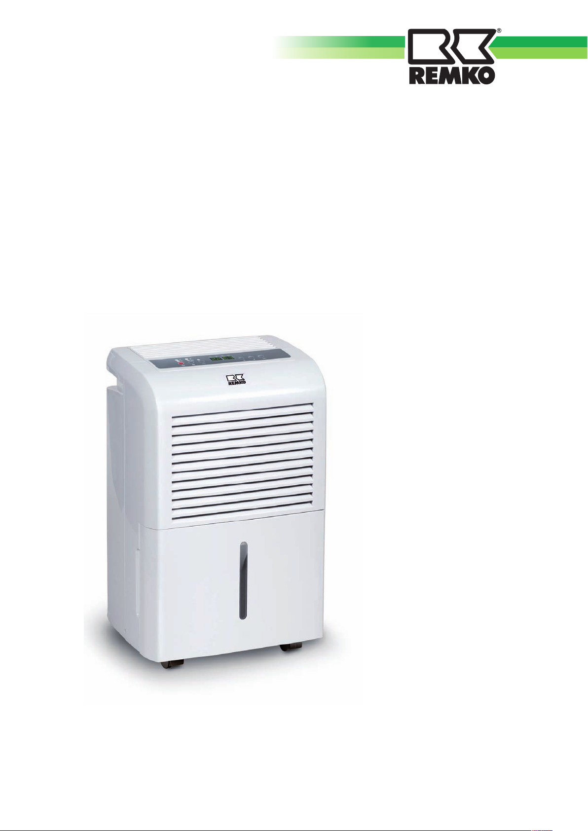
REMKO ETF 360 / ETF 460
Mobile dehumidifi ers
Operation · Technology · Spare parts
Edition GB – B01
Page 2

Page 3
Table of contents
Dehumidifi cation
Safety notices
Description of the unit
Installation
Commissioning
Decommissioning
Transporting the unit
Care and maintenance
Troubleshooting
Electrical wiring diagram
Intended use
Customer service and warranty
Environmental protection and recycling
4-6
6
7
8
8-11
11
12
12-13
13-14
14
15
15
15
Exploded drawing
Spare parts list
Maintenance report
Technical data
These operating instructions must be read carefully before
commissioning/using the unit!
16
17
18
19
Made by REMKO
These instructions are part of the unit and must always be kept in the
direct vicinity of the site of installation or at the unit.
We reserve the right to make changes; no liability for errors and misprints!
3
Page 4
REMKO ETF 360/460
Dehumidification
The interrelated processes
occurring during dehumidification
are based on physical laws.
These are illustrated here in
simplified form in order to explain
the principle of dehumidification.
Using REMKO dehumidifiers
■
No matter how well windows
and doors are insulated, damp
and moisture can penetrate
even through thick concrete
walls.
■
The water volumes required
for binding concrete, mortar,
plaster, etc. are diffused out
initially after 1-2 months under
certain circumstances.
■
Even moisture that has
penetrated masonry following
high water or flooding is
released very slowly.
■
This applies similarly, e.g. to the
moisture contained in stored
materials.
The moisture (water vapour)
escaping from buildings or
materials is absorbed by the
ambient air. This increases its
moisture content and ultimately
results in corrosion, mould, rot,
peeling of paint coatings and other
unwanted moisture damage.
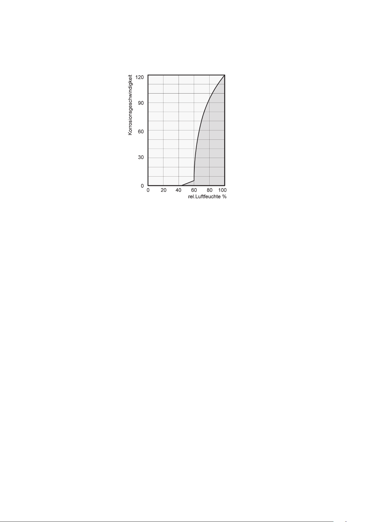
The diagram opposite shows an
example of the rate of corrosion,
e.g. for metal at different humidity
levels.
It can be seen that the rate of
corrosion below 50% relative
humidity is insignificant and can
be disregarded below 40% relative
humidity.
The rate of corrosion increases
considerably from 60% relative
humidity. This humidity damage
limit applies also to numerous
other materials, e.g. powders,
packaging, wood or electronic
equipment.
Buildings can be dried out in
different ways:
1. Heating and air exchange:
The room air is heated to absorb
moisture to subsequently be
discharged to the atmosphere.
The total input energy is lost
with the discharged, moist air.
2. Dehumidification:
The moist air in an enclosed
room is continuously
dehumidified according to the
condensation principle.
In terms of energy consumption,
dehumidification has one decisive
advantage:
Energy expenditure is restricted
solely to the existing room volume.
The mechanical heat released
through the dehumidification
process is returned to the room.
With correct use, the dehumidifier
consumes only about
energy required for the “heating
and ventilation” principle
Relative humidity
Ambient air is a gas mixture
and always contains a certain
amount of water in the form of
water vapour. This water volume
is expressed in g per kg dry air
(absolute water content).
1m3 air weighs about 1.2 kg at
20°C
Depending on the temperature,
each kg of air is only able to
absorb a certain amount of water
vapour. When this absorptive
capacity is reached, reference is
made to “saturated” air; this has a
relative humidity of 100%.
Relative humidity is therefore
understood to be the ratio
between the amount of water
vapour currently contained in
the air and the maximum water
vapour volume at the same
temperature.
The ability of air to absorb water
vapour increases with increasing
temperature. This means that
the maximum (= absolute) water
content increases with increasing
temperature.
25% of the
.
4
Page 5
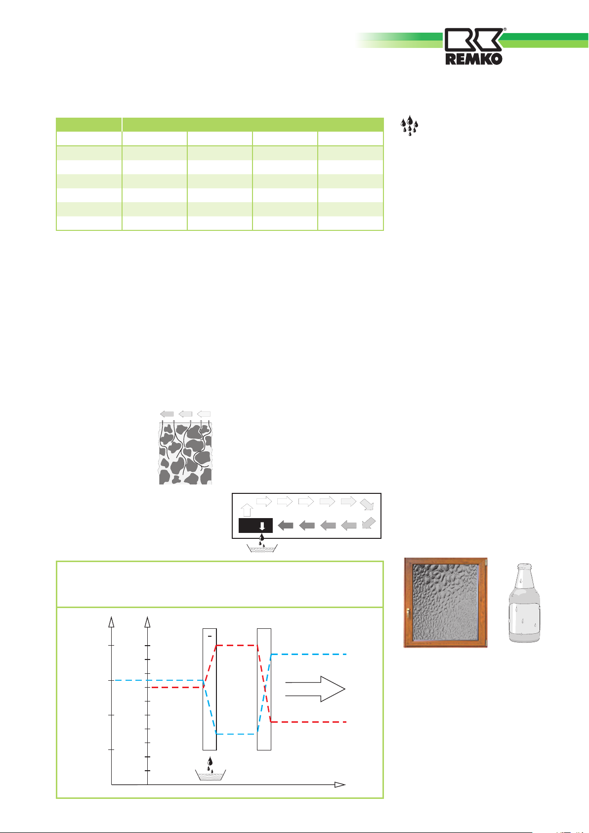
Temp. Water vapour content in g/m3 at a humidity of
°C 40% 60% 80% 100%
-5 1.3 1.9 2.6 3.3
+10 3.8 5.6 7.5 9.4
+15 5.1 7.7 10.2 12.8
+20 6.9 10.4 13.8 17.3
+25 9.2 13.8 18.4 23.0
+30 12.9 18.2 24.3 30.3
Drying materials
Building materials or structures
can absorb substantial amounts
of water, e.g. bricks 90-190 l/
m³, heavy concrete 140-190 l/m³,
lime-sand bricks 180-270 l/m³.
The drying out of moist materials,
e.g. masonry, takes place as
■
The air enriched with
water vapour continuously
circulates through the REMKO
dehumidifi er. It is dehumidifi ed
and leaves the unit at a slightly
higher temperature to absorb
water vapour from anew
follows:
■
In this way, the moisture
■
The contained moisture moves
from the inside of
the material to its
contained in the material is
gradually reduced
The material dries!
surface
The produced condensation
■
Evaporation takes
place on the
is collected in the unit and
discharged.
surface = transition as water
vapour to the ambient air
Condensation of water
vapour
Since the maximum water vapour
volume increases when the air is
heated, but the contained water
vapour volume remains the same,
this results in a reduction of the
relative humidity.
In contrast, when the air is
cooled, the capacity to absorb the
maximum water vapour volume
reduces, the water vapour volume
contained in the air remains the
same and the relative humidity
increases.
If the temperature falls further, the
capacity to absorb the maximum
water vapour volume is reduced
until it is equal to the contained
water vapour volume.
This temperature is called dewpoint temperature. When the air
is cooled below the dew-point
temperature, the contained water
vapour volume is larger than the
maximum possible water vapour
volume.
Water vapour is discharged.
This condenses to water, moisture
is removed from the air.
Examples of condensing are misted
windows in winter or misting of a
cold drinks bottle.
The air fl ow is cooled on its way through or via the evaporator to
below the dew-point. The water vapour condenses and is collected
in a collection tray and discharged.
°C
% r.F.
Verdampfer Kondensator
+
30
25
20
15
100
90
80
70
60
50
40
30
20
10
Lufttemperatur
Luftrichtung
Luftfeuchte
-
+
Verlauf
The higher the relative humidity,
the higher the dew-point
temperature, which is easier to fall
below.
5
Page 6

REMKO ETF 360/460
Heat of condensation
The energy transferred from the
condenser to the air is composed
of:
1. Heat energy previously removed
in the evaporator.
2. Electrical motive energy.
3. Heat of condensation released
during liquefaction of the water
vapour.
For the change from a liquid to a
gaseous state, energy is necessary.
This energy is called heat of
evaporation. It does not cause
any rise of temperature, it is only
necessary for the change from a
liquid to a gaseous state.
Vice versa, energy is released
during the liquefaction of
gas, which is called heat of
condensation.
The amount of heat of evaporation
and condensation is the same.
For water, this is:
2250 kJ/kg (4.18 kJ = 1kcal)
This shows that a relatively large
amount of energy is released
through the condensation of water
vapour.
If the moisture to be condensed
is not introduced through
evaporation in the room itself, but
from outside, e.g. via ventilation,
the heat of condensation released
in the process contributes towards
room heating. In drying processes,
the heat energy is recirculated,
which is consumed during
evaporation and released during
condensation. The supplied air
during dehumidification creates
a large amount of heat energy,
which is expressed as a rise of
temperature.
The time necessary for drying
normally does not depend only
on the unit capacity, but is rather
determined by the rate at which
the material or parts of the
building release their moisture.
Safety notices
The units were subjected to
extensive material, function and
quality inspections and tests prior
to delivery.
However, the units may constitute
a hazard if used by persons who
have not been instructed in their
use, improperly or not for the
intended purpose.
The following information must
be observed:
■
The units must not be installed
or operated in locations subject
to explosion hazards
■
The units must not be installed
and operated in oil, sulphur,
chlorine or salt containing
atmospheres.
■
The units must be installed
upright and stable.
■
The units must not be exposed
to a direct jet of water.
■
The air inlet and outlet must
always be kept free.
■
The air intake grilles must
always be kept free from dirt
and loose objects
■
The units must not be covered
whilst in operation.
■
Never insert foreign objects into
the units
■
The units must not be
transported during operation.
■
The units must only be
transported upright (water
spillage).
■
All electric cables outside the
units must be protected against
damage, e.g. by animals, etc.
■
The condensation collectors
must be emptied prior to each
change of location.
ATTENTION
Only qualified electricians may
extend the connecting cable
taking into account the rating
of the unit, cable length and
use locally.
ATTENTION
All work on the refrigeration
system and electrical
equipment must be referred
to an authorised specialist
company!
6
Page 7
Description of the unit
The units are designed for
universal and problem-free
dehumidifi cation.
Owing to their compact size, they
are easy to transport and install.
The units operate according
to the condensation principle
and have a hermetically sealed
refrigeration system, hot gas
defrosting, low-noise and lowmaintenance circulating fan as well
as connecting cable with plug.
The fully automatic control,
condensation collector with
integrated overfl ow protection
and drain connection for direct
condensation drainage or
condensation pump connection
ensure trouble-free operation.
The units comply with the
fundamental safety and health
requirements of the pertinent EU
directives.
The units are reliable and easy to
operate.
The units are used wherever it
is important to have dry rooms
and consequential damage (e.g.
through mould formation) is to be
avoided.
Operation
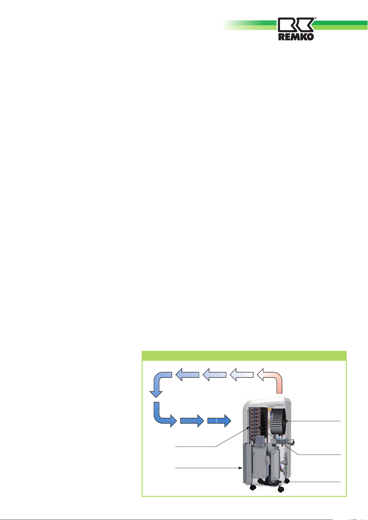
The circulation fan can be started
by pressing the Power button. The
installed moisture sensor controls
compressor operation.
The circulation fan draws in the
humid room air via the air inlet
grille with fi lter, evaporator and
temperature and relative humidity,
the condensed water drips
constantly or only during the
defrost phase into the collection
tray and subsequently into the
condensation collector located
below.
following condenser.
A fl oat in the condensation
At the cold evaporator, heat is
extracted from the room air and
cooled to below the dew-point.
collector interrupts
dehumidifi cation via a microswitch
when the collector is full.
The water vapour contained in the
room air deposits as condensation
or frost on the evaporator fi ns.
The units switch off and the
“Collector full” indicator light on
the control panel fl ashes.
At the condenser (heat exchanger),
the cooled and dehumidifi ed air is
reheated and blown back into the
room via the air outlet grille at a
slightly increased temperature of
about 5°C to 10°C above room
This does not extinguish until the
emptied condensation collector is
refi tted.
Dehumidifi cation then restarts as
required, possibly with a delay of
about 3 minutes.
temperature.
The conditioned drier air
continuously mixes with the room
air.
Due to the constant circulation of
the room air through the unit, the
relative humidity in the installation
room is gradually reduced to the
required humidity (% RH).
In unsupervised continuous
operation with external
condensation connection,
the produced condensation is
continuously drained via a hose
connection or pumped out by the
installed condensation pump as
required.
Depending on the room air
Schematic diagram showing the mode of operation of the REMKO dehumidifi er
The units are also suitable for
drying and dehumidifi cation of:
■
Living areas, bedrooms, shower
or cellar rooms
■
Utility rooms, weekend homes,
caravans
■
Warehouses, archives,
laboratories
■
Bathrooms, washrooms and
changing rooms, etc.
■
Cellar rooms, store rooms
Dehumidifi ed
room air
Humid room air
Circulation fan
Evaporator
Condenser
Condensation collector
Compressor
7
Page 8
REMKO ETF 360/460
Installation
For optimal, economical and
reliable operation of the unit, the
following information must be
observed in any event:
■
The units must be installed
stable and horizontal to ensure
unhindered condensation
drainage.
■
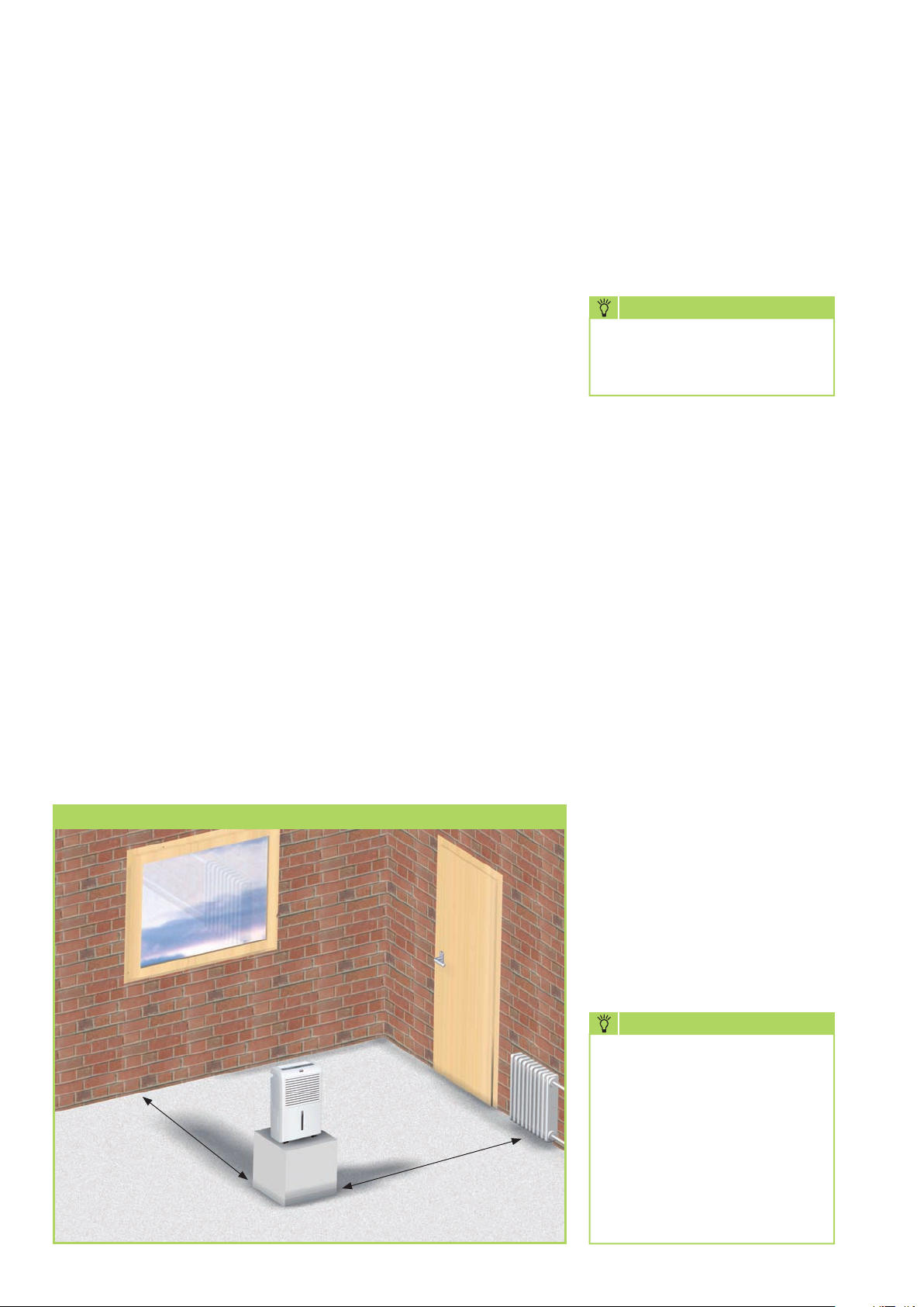
The units should be placed in
the centre of the room where
possible to ensure optimal air
circulation.
■
It must be ensured that the
room air can be sucked in and
blown out freely.
■
A minimum distance of 50 cm
to walls must be maintained in
any event.
are installed about 1 m above
ground.
■
The room to be dried or
dehumidified must always
be closed from the ambient
atmosphere.
■
Open windows, doors, etc., as
well as frequently entering and
leaving the room should be
avoided as far as possible.
■
The units must not be used
in dusty, chlorine or ammonia
containing atmospheres.
■
The unit output depends
solely on the room conditions,
room temperature, relative
humidity and observance of the
installation instructions.
Commissioning
Prior to each commissioning or
depending on the local conditions,
the air inlet and outlet grilles must
be checked for clogging.
NOTE
Clogged grilles and filters must
immediately be cleaned or
replaced.
Important information prior to
commissioning
■
Do not pull at the power cord.
■
After switching on, the units
operate fully automatically until
switched off controlled by the
hygrostat or float switch of the
full condensation collector.
■
The units should not be installed
in the immediate vicinity of
radiators or other heat sources.
■
Optimal room air circulation
is achieved when the units
Diagram showing installation of the REMKO dehumidifier
Keep windows and doors closed!
Min. wall di-
stance 0.5 m
Maintain distance to radiators or
other heat sources.
■
The condensation collector
must be fitted correctly.
The unit will not function if the
condensation collector is not
fitted correctly!
■
If the units are to operate
continuously with an external
condensation connection, the
respective chapter on page 11
must be observed.
NOTE
In order to prevent compressor
damage, the units are
provided with reclosing
protection, which prevents
immediate reconnection
of the compressor after
disconnection.
The compressor initially
switches on again after a delay
of about 3 minutes!
8
Page 9
Electrical connection
Control panel
Set the humidity
■
The units operate on 230 V
AC/50Hz
■
Electrical connection
takes place using the
fi tted power cord
with safety plug.
NOTE
Electrical connection must take
place to supply points using a
residual-current protective unit
according to VDE 0100, part 704.
For installation of the units in damp
areas such as utility rooms, shower
rooms or similar, the units must be
protected with a residual-currentoperated circuit-breaker complying
with the requirements.
■
Extension of the connecting
cable must only take place by
qualifi ed electricians, taking into
account the cable length, unit
installed load and local use.
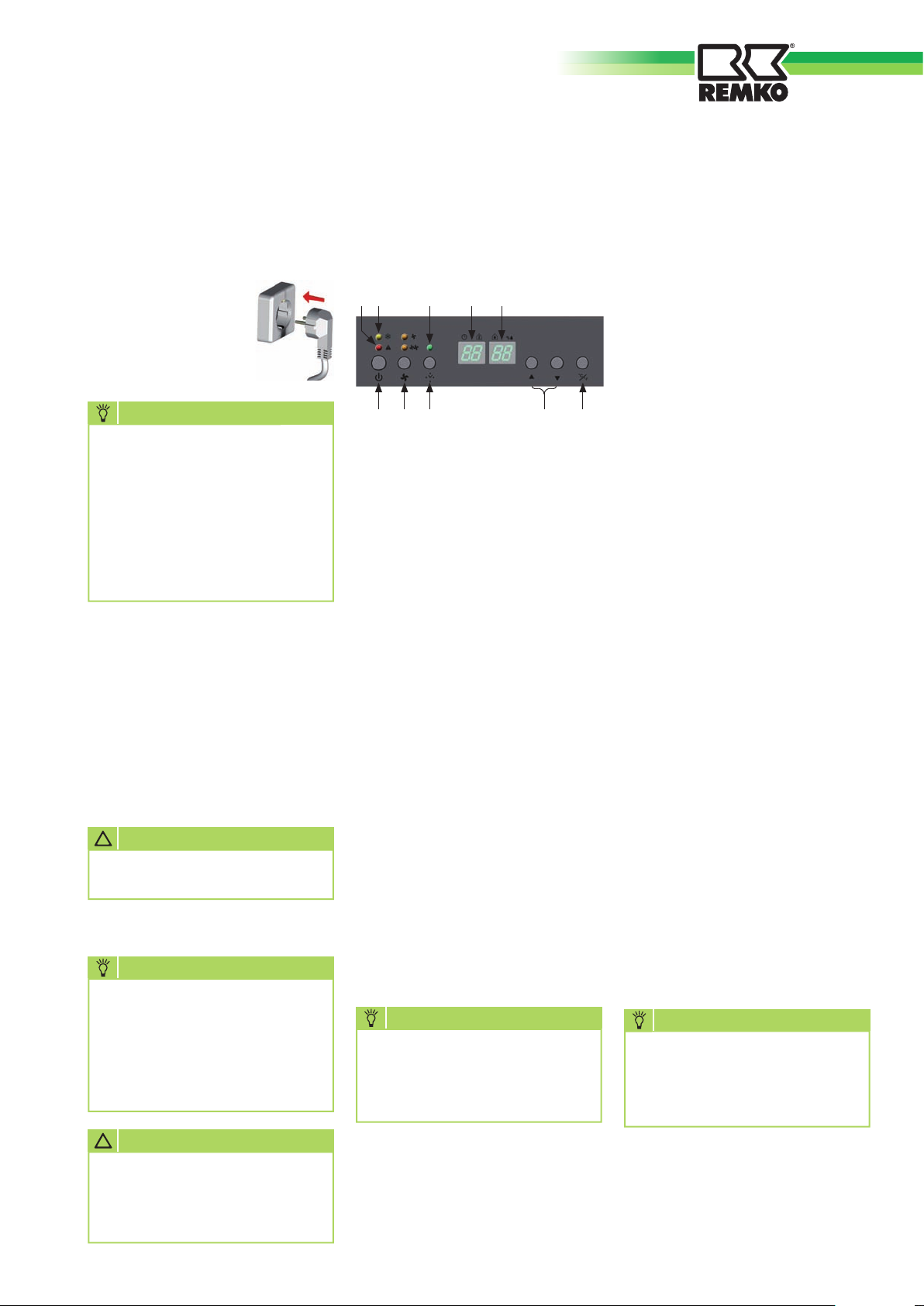
The control panel contains all
controls and respective indicator
lights.
“Container full” indicator
“Hot gas defrost” indicator
“Timer activated” indicator
Temperature indication and
time setting display
Relative humidity indication
and setting display
“Power ON/OFF” button
Fan speed button
“1 to 24 hour” timer button (in
1 hour steps)
The dehumidifi cation capacity
depends solely on the room
conditions, room temperature,
relative humidity and observance
of the information in the chapter
“Installation”.
The higher the room temperature
and relative humidity, the greater
the dehumidifi cation capacity.
For use in living areas, a
humidity of about 45 to 60% is
recommended.
In warehouses, archives, etc., a
humidity of 40 to 45% should not
be exceeded.
■
Select the required humidity (%
RH) with the buttons [].
The set value is indicated
for about 10 seconds on the
display [].
■
The humidity can be set in steps
of 30 - 90% RH.
!
ATTENTION
All cable extensions must only
be used uncoiled or unwound.
NOTE
At room temperatures below
10 °C
and a relative humidity
below
40 %
, economical/
effi cient use of the unit is not
ensured.
!
ATTENTION
To avoid overheating, the
air outlet grille must not be
covered when the unit is in
operation.
Button for setting hygrostat 30
to 90% RH in 5% steps
Button for indication in °C or °F
Switching on the units
■
Connect the mains plug to a
correctly fused mains socketoutlet.
NOTE
The units generate a short
beep on connection to the
mains supply and all indicators
fl ash once.
■
Press the Power button [].
■
Select the required air volume
(min/max) by pressing the
button [].
■
In a normal operating mode,
the current humidity is
indicated on the display [] in
% RH.
■
The current room temperature is
indicated on the display [] in
°C or °F.
Indication selection can be made
by pressing the button [].
NOTE
After reaching the required
humidity, the compressor
switches off and air circulation
continues..
s
s
s
9
Page 10
REMKO ETF 360/460
s
s
s
Activate timer
With the timer function, automatic
“ON/OFF” switching functions
can be preselected up to 24 hours
(in a one hour cycle).
Timer switching functions
Adjustment during operation:
The unit switches OFF depending
on the selected number of hours.
Adjustment must be made with
the unit switched off (the mains
plug must be connected to a mains
socket).
The unit switches ON depending
on the selected number of hours.
■
The timer function can be
activated with the [] button
and the required time selected in
hour steps (max. 24 hours).
Automatic defrost
The moisture contained in the
room air condenses on cooling and
covers the evaporator fins with
frost or ice depending on the air
temperature and relative humidity
(% RH).
The automatic defrost function
integrated in the unit activates the
defrost cycle as required.
The frost or ice on the exchanger
surfaces can be defrosted using
hot gas as necessary.
This particularly fast and effective
defrost method guarantees a high
dehumidification capacity.
Dehumidification is interrupted
only briefly during the defrost
phase.
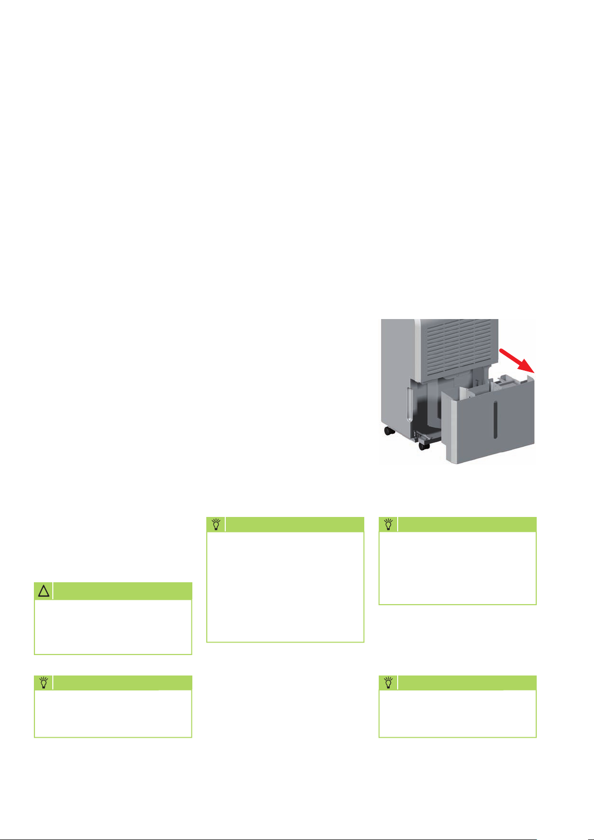
Emptying condensation
collector
The installed condensation
collector must be emptied from
time to time depending on the
amount of condensation produced.
When the condensation collector
is full, operation is interrupted and
the “Collector full” indicator light
[] flashes to show this status.
1. Carefully pull out the full
collector.
The entered value flashes in the
display [] for about 10 seconds.
An activated timer is indicated
constantly by the indicator light
[] at the control panel.
!
ATTENTION
All programmed values/
settings are deleted when the
unit is disconnected from the
mains.
NOTE
The unit cannot be controlled
via an external timer.
The indicator light [] shows that
the hot gas defrost cycle is active.
NOTE
At a sufficiently high room
temperature, no frost normally
forms on the fin surface,
obviating the need for
defrosting.
This makes the dehumidifier
operate highly efficiently.
2. Empty the collector at a suitable
place.
NOTE
After each emptying, the
condensate container including
float must be checked for possible damage, fouling, etc.
3. Carefully place the emptied and
checked condensation collector
back in the unit.
NOTE
The unit will only start when
the condensation collector is
correctly seated.
10
The “Collector full“ indicator light
extinguishes and the unit continues
to operate fully automatically.
Page 11
Decommissioning
Continuous operation with
external condensation drain
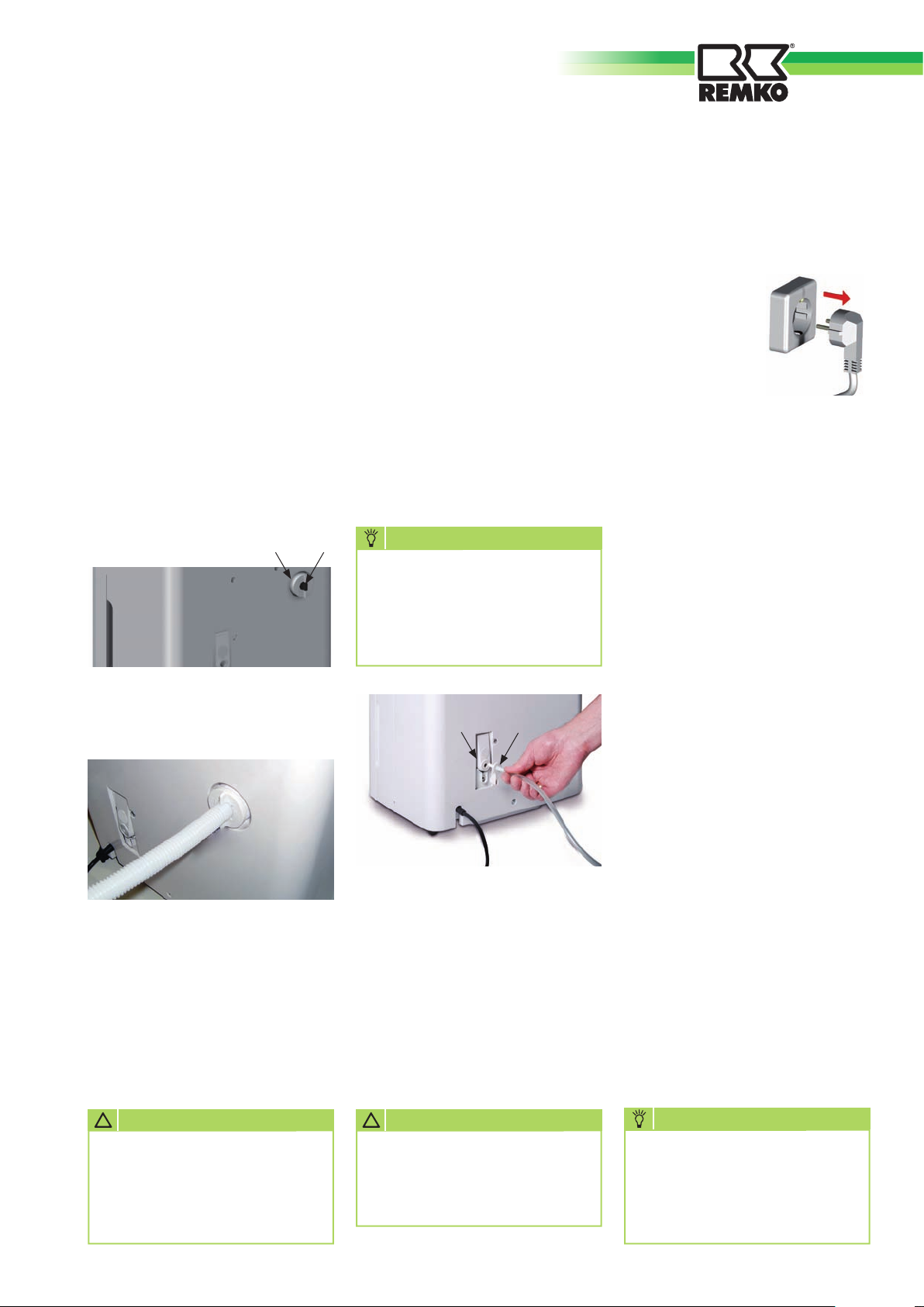
The units have a condensation
connection at the rear.
A supplied (1m) special drain hose
can be connected at this point.
1. Unscrew the screw cap [A] (turn
counter-clockwise).
2. Pull the sealing plug [B] out of
the connection.
3. Push the smooth end of the
drain hose through the back of
the screw cap [A].
A B
Continuous operation via the
internal condensation pump
For uses at locations with no drain,
the units are provided with a
condensation pump specifi cally for
this purpose.
This allows various condensation
drains to be provided to suit the
conditions locally.
The patented condensation pump
connection panel [KP] is located at
the rear of the units.
Insert the supplied connection
adapter [SA] here.
NOTE
The pump will only function
when the supplied connection
adapter [SA] is correctly connected.
Press the Power button [].
-All indicators and unit functions
are now switched off-
The units must be
disconnected from
the supply if they
are not going to be
used for extended
periods of time.
The condensation collector must
be emptied completely and dried
with a clean cloth.
Pay attention to subsequently
dripping condensation!
Prior to possible storage, the units
must be cleaned thoroughly and
dried.
4. Screw the drain hose with
the screw cap [A] to the
connection..
The condensation should
preferably be discharged to a lower
drain in unsupervised continuous
operation.
When using an external collection
container (tray, bucket, etc.), the
unit must be raised appropriately.
KP SA
The factory supplied hose length is
5 metres.
This can be extended on site to
max. 10 metres if required.
A height different of up 5 metres
can be bridged with the installed
condensation pump.
The internal collection tray must be
emptied of residual condensation
prior to each change of location.
To do this, open the condensation
connection with the screw cap [A]
and the sealing plug [B].
Tilt the unit back slightly and
empty the residual condensation
into a suitable container.
The condensation connection must
subsequently be carefully closed
again in reverse order.
For storage purposes, the units
should be covered with plastic
sheeting/foil or cotton cloth and
stored in an upright position in a
protected and dry location.
!
ATTENTION
It must be ensured that the
drainage hose is routed to the
drain with a gradient to ensure
that the condensate is able to
fl ow out freely!
!
ATTENTION
After connecting the adapter
[SA], the pump is ready to use
and can immediately pump
water.
NOTE
The units must only be
stored in upright in a suitable
location protected from dust
and direct sunlight.
11
Page 12
REMKO ETF 360/460
Transporting the unit
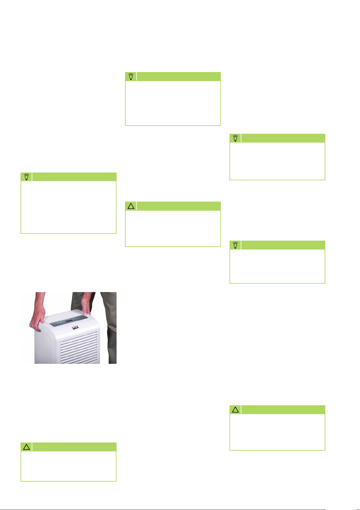
For easy and convenient transport,
the units are provided with four
transport rollers and additional
recessed grips.
■
The unit must be switched off
and the plug disconnected from
the mains socket prior to each
change of location.
■
The condensation collector
must be emptied completely.
NOTE
Attention must be paid to
dripping condensation.
After switching off the unit,
the evaporator can continue to
defrost under the influence of
the ambient temperature.
■
As long as residual moisture is
still present in the evaporator
or water is present in the
condensation collector, the
units must only be transported
upright.
Care and maintenance
NOTE
Regular care and maintenance
is a basic precondition for a
long useful life and troublefree operation of the unit.
All moving parts are provided
with low-maintenance permanent
lubrication. The entire refrigeration
system is hermetically sealed
and must only be repaired by
authorised specialist companies.
!
ATTENTION
Before carrying out work on
the units, the mains plug must
be disconnected from the
mains socket.
■
Observe regular care and
maintenance intervals
■
Depending on the particular
operating conditions, the
units should be tested by an
expert for reliable operation as
necessary, but at least once a
year
Cleaning the condenser and
evaporator
For cleaning the interior of the unit
and to gain access to the electrical
components, it is necessary to
open the unit housing.
NOTE
Only authorised specialists
may undertake repairs and
maintenance.
■
Clean the condenser and
evaporator by either blowing
out with air, vacuuming or
using a soft brush.
Do not use a jet of water!
NOTE
The fin exchanger must be
cleaned with particular care
as the delicate aluminium fins
bend easily.
■
Carefully clean the internal
surfaces of the units, collection
tray with condensation pump
float, fan and fan housing.
■
The transport rollers are only
suitable for use on even and
level surfaces.
■
The units must be carried if
surfaces are uneven.
!
ATTENTION
The power cord must never
be used for pulling or fixing
purposes.
12
■
Only clean the units dry or with
a moist cloth.
Do not use a jet of water!
■
Do not use caustic cleaning
agents or those containing
solvents
■
Only use suitable cleaning
agents to remove heavy fouling
■
Regularly check the air inlet and
outlet grilles for fouling.
Clean or replace as necessary!
■
Check all unit components for
possible damage and repair if
necessary.
■
Carefully refit all previously
removed components in the
reverse order.
!
ATTENTION
After carrying out all work on
the units, an electrical safety
test must be carried out in
accordance with VDE 0701.
Page 13
Troubleshooting
Filter cleaning
The unit is provided with an air
inlet grille with integrated air fi lter
to prevent damage.
To prevent a reduction in
performance and faults, the air
inlet grille with fi lter must be
checked as required, however at
least every two weeks and cleaned
if necessary.
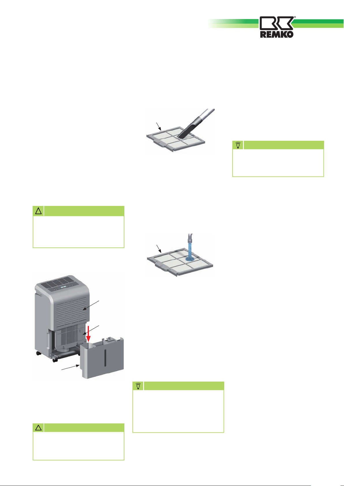
1. Switch off the unit at the control
panel (button []).
2. Disconnect the mains plug from
the mains socket.
!
ATTENTION
All programmed values/
settings are deleted when the
unit is disconne cted from the
mains.
3. Remove the condensation
collector [K].
5. Carefully clean the air fi lter [F]
with a soft brush or vacuum
cleaner.
F
6. A heavily clogged fi lter [F]
can be washed in a warm
(maximum 40°C) soap solution.
Subsequently rinse thoroughly
with clear water and allow to
dry!
F
The units were manufactured using
the latest production methods
and tested repeatedly for perfect
function.
If faults should still occur, the unit
must initially be checked against
the following list.
NOTE
Repairs must only be carried
out by authorised specialists.
The unit does not start:
■
Check The timer programming
Indicator light [] lit?
■
Check the mains connection and
local mains fuse -230V/1~/50
Hz
■
Check the mains plug and
power cord for damage
G
F
K
4. Pull out the air fi lter [F] located
behind the air inlet grille from
below.
!
ATTENTION
The units must not be used
without air inlet grille and air
fi lter fi tted!
7. The air inlet grille [G] must also
be checked for clogging and
cleaned if necessary.
8. Prior to refi tting, it must be
ensured that the air inlet
grille [G] and air fi lter [F]
are completely dry and
undamaged.
NOTE
Heavily fouled or damaged air
fi lters must be replaced with
new ones.
Only original spare parts must
be used.
■
Check the level in the
condensation collector
Check for correct seating
The “Collector full” indicator
light [] must not fl ash!
■
Test the function of the
condensation collector
microswitch [MS].
■
Check for free air intake and
discharge
Overheating!
■
Check fuse on the control
board
This work makes it necessary
to open the unit which must
only be carried out by an
authorised specialist company.
s
s
s
13
Page 14
REMKO ETF 360/460
s
s
s
The unit operates, but
without condensation
■
Check the hygrostat setting
The setting must be lower than
the relative installation room
humidity!
■
Check the air inlet grille and air
filter for fouling.
Clean or replace if necessary!
■
Have the exchanger fins
checked for fouling.
This work makes it necessary
to open the unit which must
be carried out only by an
authorised specialist company!
The unit is noisy or
condensation discharges
■
Check that the unit is standing
on a level and firm surface.
■
Check that the unit is standing
upright and stable.
■
Have the collection tray or
connection checked for dirt
deposits.
This work makes it necessary
to open the unit which must
be carried out only by an
authorised specialist company!
!
ATTENTION
All work on the refrigeration
system and electrical
equipment must be referred
to an authorised specialist
company!
Note on refrigerant
The units are operated with
environmentally-friendly
and ozone neutral refrigerant
R410a.
According to statutory
and local regulations, the
refrigerant/oil mixture
contained in the unit must be
disposed of properly.
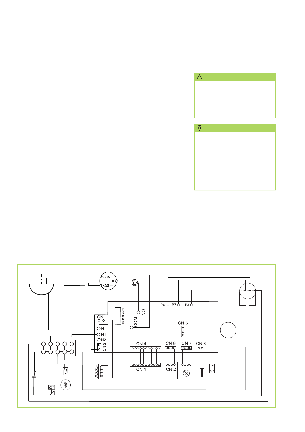
Electrical wiring diagram
230V~50Hz
L N
GELB/
GRUEN
BRAUN
PE
BRAUN
Pumpen
Protector
WEISS
Kondensator
BLAU
BLAU
ROT
WEISS
BLAU
Pumpe
WEISS
BLAU
Kompressor
BLAU
Transformator
BLAU
BLAU
SCHWARZ
Sicherung
OLP
ROT
Ventilatorspeed
Steuerplatine
Bedienplatine Feuchte-
GELB
min.
ROT
max.
sensor
BRAUN
BLAU
Temperatursensor
Mikroschalter
Ventilator
M~
WEISS
Kondensator
2-Wege
Magnetventil
BLAU
14
Page 15
Intended use
The units are designed and
equipped for drying and
dehumidifi cation purposes.
The units must not be used for any
other purposes.
The units must only be operated
by suitably trained persons who
are familiar with the operation of
the unit.
The manufacturer is not liable for
any damage attributed to failure
to observe the manufacturer‘s
instructions or applicable statutory
requirements or unauthorised
changes to the unit.
Customer service and
warranty
A precondition for any warranty
claims is that the dealer or his
customer has completed and
returned the enclosed “warranty
document” to REMKO GmbH &
Co. KG.
The units were repeatedly tested
at the factory to ensure that they
function correctly.
Nonetheless, if the unit should
have a fault that cannot be
remedied by troubleshooting,
your specialised dealer or contract
partner should be contacted.
Environmental
protection and
recycling
Disposal of packaging
When disposing of the packaging
material, please think of the
environment.
Our units are carefully packed for
transport and delivered in sturdy
cardboard packaging on a wooden
pallet, if necessary.
The packaging materials are
environmentally-friendly and can
be recycled.
By reusing packaging material,
you make a valuable contribution
towards waste reduction and the
conservation of raw materials.
Only dispose of packaging
material at the facilities provided.
NOTE
Operation for any other
purpose than that described in
these operating instructions is
not permitted.
Non-observance will result in
all liability being disclaimed
and invalidate the warranty.
!
ATTENTION
Copyright
Any copying of this document
in whole or part or use for
purposes other than that
intended is strictly forbidden
without the prior written
permission of
REMKO GmbH & Co. KG
.
NOTE
Only authorised specialists
may undertake repairs and
maintenance.
Important information on
recycling
The units are operated with
environmentally-friendly and
ozone neutral refrigerant R410a.
The refrigerant and oil mixture
contained in the unit must be
disposed of properly in accordance
with the statutory and locally
applicable regulations.
Disposal of the old unit
This unit must not be disposed of
together with normal household
waste, but must be taken to
a special collection point for
recycling electrical and electronic
equipment.
The materials can be reused
according to their marking.
The reuse or recycling of materials
and old units makes an important
contribution towards protecting
the environment.
To fi nd out about your nearest
disposal facilities, contact your
local authorities.
15
Page 16
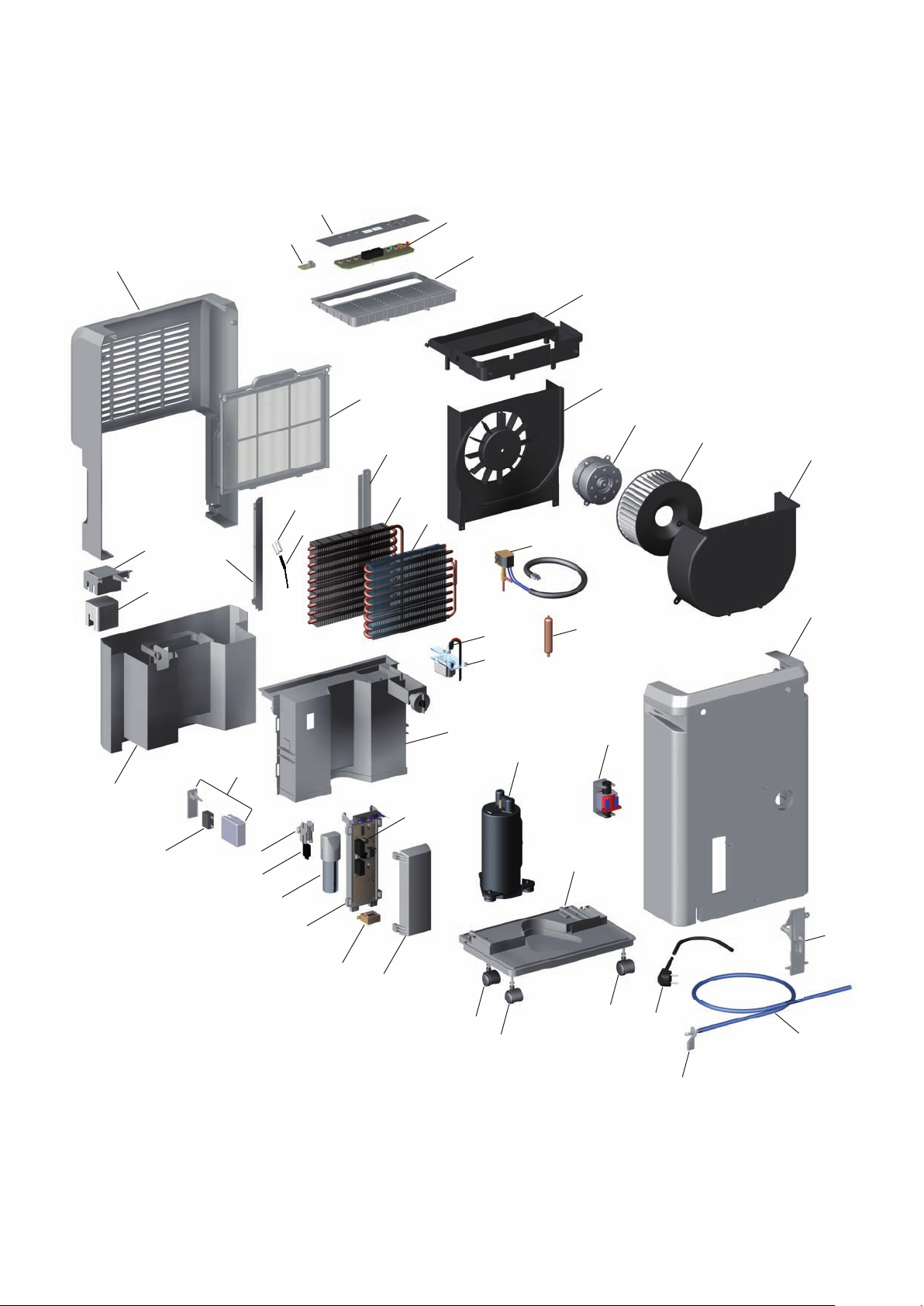
REMKO ETF 360/460
Exploded drawing
29
35
36
24
30
27
26
32
28
24
23
22
31
20
10
09
19
18
17
16
15
12
14
13
37
39
40
41
42
43
44
47
45
46
38
02
02
03
01
08
02
07
04
06
05
16
We reserve the right to make changes to dimensions and the design in the interest of technical advances.
Page 17
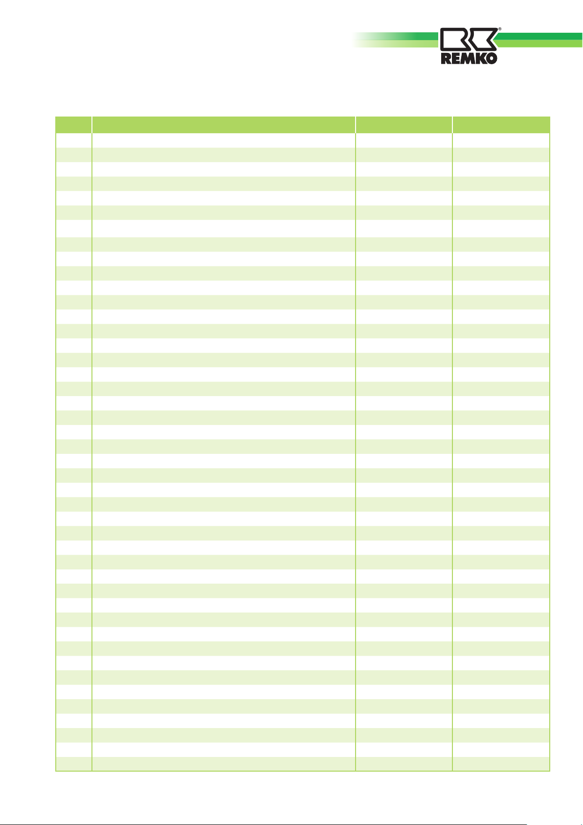
Spare parts list
No. Bezeichnung ETF 360 ETF 460
EDP No. EDP No.
01 Base plate 1111850 1111850
02 Transport roller 1111851 1111851
03 Compressor, complete 1111852 1111853
04 Power cord with plug 1111854 1111854
05 Connection adapter
06
07
Condensation hose, running metre (for condensation pump operation)
Connection panel, complete (for condensation pump operation)
08 Condensation pump 1111858 1111858
09 Float, complete
10 Microswitch
(for condensation pump operation) 1111860 1111860
12 Solenoid valve, complete 1111861 1111861
13 Dry fi lter 1111862 1111862
14 Rear panel 1111863 1111863
15 Fan housing 1111864 1111864
16 Fan impeller 1111865 1111865
17 Fan motor 1111866 1111866
18 Fan supporting plate 1111867 1111867
19 Supporting plate, top 1111868 1111868
20 Air outlet grille 1111869 1111869
22 Fin condenser 1111870 1111871
23 Fin evaporator 1111872 1111872
24 Guide rails (set) 1111873 1111873
26 Temperature sensor 1111874 1111874
27 Retaining bracket for temperature sensor 1111875 1111875
28 Air fi lter 1111876 1111876
29 Housing front panel 1111877 1111877
30 Sensor board (humidity) 1111878 1111878
31 Control board 1111879 1111879
32 Control panel (membrane) 1111880 1111880
35 Float housing 1111881 1111881
36 Float 1111882 1111882
37 Condensation collector, complete 1111883 1111883
38 Centre panel 1111884 1111884
39 Capacitor (fan motor) 1111885 1111885
40 Protective housing (capacitor) 1111886 1111886
41 Microswitch holder 1111887 1111887
42 Microswitch 1111888 1111888
43 Capacitor (compressor) 1111889 11118990
44 PC board housing 11118991 11118991
45 Cover (PC board housing) 11118992 11118992
46 Control board 11118993 11118993
47 Transformer 11118994 11118994
Not shown
Fuse (on control board) 11118995 11118995
(for condensation pump operation) 1111855 1111855
1111856 1111856
1111857 1111857
(for condensation pump operation) 1111859 1111859
When ordering spare parts, please always quote the EDP No. and serial number (see rating plate!)
17
Page 18

REMKO ETF 360/460
Maintenance report
Unit type: .................................. Serial number: ...................................
1 2 3 4 5 6 7 8 9 10 11 12 13 14 15 16 17 18 19 20
Unit cleaned - externally -
Unit cleaned - internally -
Fan impeller cleaned
Fan housing cleaned
Condenser fins, cleaned
Evaporator fins, cleaned
Fan function tested
Air inlet grille with filter cleaned
Unit checked for damage
Protective devices checked
All fixing screws checked
✍
Check for electrical safety
Test run
Remarks: .............................................................................................................................................................
.............................................................................................................................................................................
.............................................................................................................................................................................
1. Date: .................
..............................
Signature
6. Date: .................
..............................
Signature
11. Date: ...............
..............................
Signature
2. Date: .................
..............................
Signature
7. Date: .................
..............................
Signature
12. Date: ...............
..............................
Signature
3. Date: .................
..............................
Signature
8. Date: .................
..............................
Signature
13. Date: ...............
..............................
Signature
4. Date: .................
..............................
Signature
9. Date: .................
..............................
Signature
14. Date: ...............
..............................
Signature
5. Date: .................
..............................
Signature
10. Date: ...............
..............................
Signature
15. Date: ...............
..............................
Signature
16. Date: ...............
..............................
Signature
The unit must only be serviced by authorised specialists in compliance with the statutory requirements.
18
17. Date: ...............
..............................
Signature
18. Date: ...............
..............................
Signature
19. Date: ...............
..............................
Signature
20. Date: ...............
..............................
Signature
Page 19
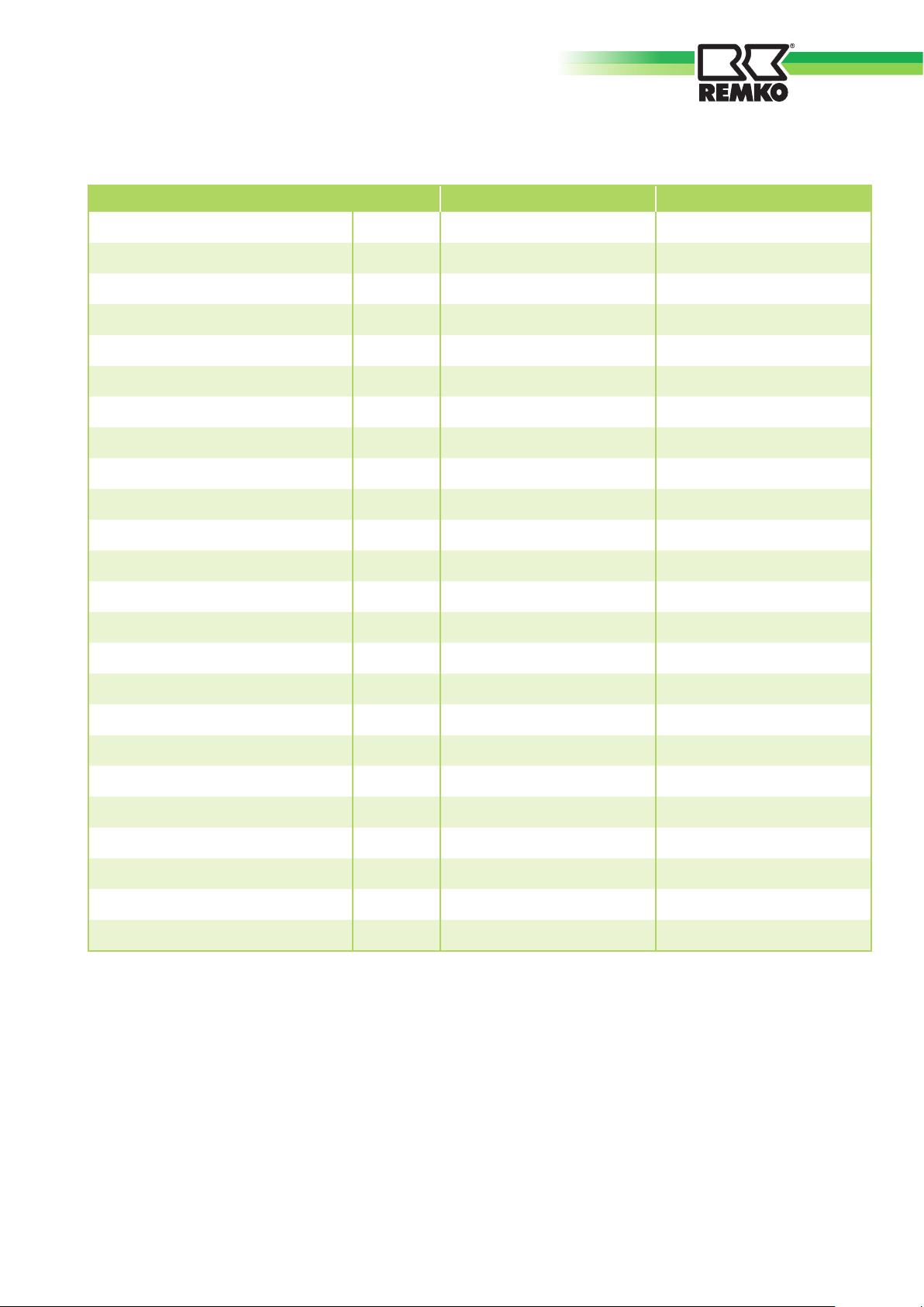
Technical data
Series ETF 360 ETF 460
Operating temperature range °C 6 to 32 6 to 32
Working area humidity
Max. dehumidifi cation capacity l/day 36 46
at 30°C/80% RH l/day 32.9 42.3
at 20°C/70% RH l/day 17.4 24.6
at 15°C/60% RH l/day 8.2 9.9
Hot gas defrosting unit --- Series Series
Air volume fl ow max./min. m
Condensation collector capacity l 6.5 6.5
Condensation pump --- incorporated incorporated
% relative
humidity
3
/h 320 / 280 310 / 270
40 to 100 40 to 100
Hose length
Delivery head
Refrigerant
(condensation pump) m 5 (10*) 5 (10*)
(condensation pump) m 5 5
1)
--- R 410A R 410A
Refrigerant quantity g 210 320
Power supply V 230/1~ 230/1~
Frequency Hz 50 50
Max. nominal current consumption A 2.7 3.95
Max. power input kW 0.55 0.89
2)
Sound pressure level LpA 1m
dB (A) 53 / 49 53 / 50
Depth mm 280 280
Width mm 390 390
Height mm 600 600
Weight kg 16.5 21
EDP No. --- 1610360 1610460
1)
Contains greenhouse gas according to Kyoto Agreement
2)
Noise measurement DIN 45635 - 01 - Category 3
* max. permissible hose length (Ø 8x6)
We reserve the right to make changes to dimensions and the design in the interest of technical advances.
19
Page 20
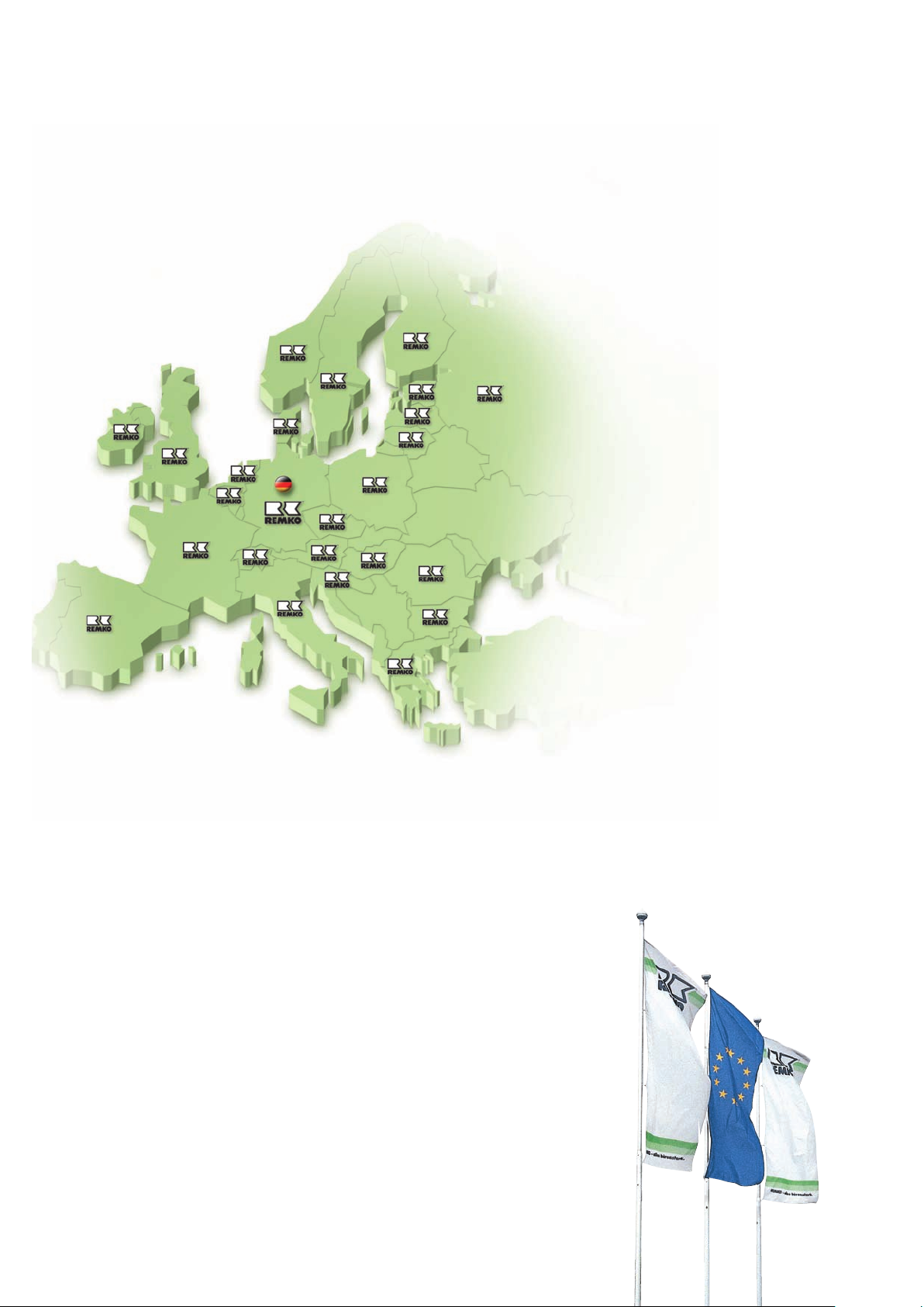
REMKO INTERNATIONAL
… and somewhere near you!
Take advantage of our experience and consulting services
Consulting
Through intensive training,
we ensure that the expert
knowledge of our consultants
is always up-to-date. This has
given us the reputation of
being more than just a good,
reliable supplier:
REMKO, a partner that helps
solve problems.
Sales
REMKO not only has an
extensive sales network
in Germany and abroad,
but also unusually highly
qualified sales experts.
REMKO field representatives
are more than just salesmen:
they are also customer
consultants in the area of
air conditioning and heating
technology.
Customer service
Our units operate precisely
and reliably. If a fault should
occur, REMKO Customer
Service is there to help you.
Our extensive network of
experienced specialised dealers
REMKO GmbH & Co. KG
Klima- und Wärmetechnik
guarantees you a fast and
reliable service
.
Im Seelenkamp 12 32791 Lage
Postfach 1827 32777 Lage
Telephone +49 52 32 606-0
Fax +49 52 32 6 06-2 60
E-mail [email protected]
Internet www.remko.de
Hotline
Germany
+49 5232 606-0
International
+49 5232 606-130
Subject to technical changes. Information subject to change.
 Loading...