

Page 1
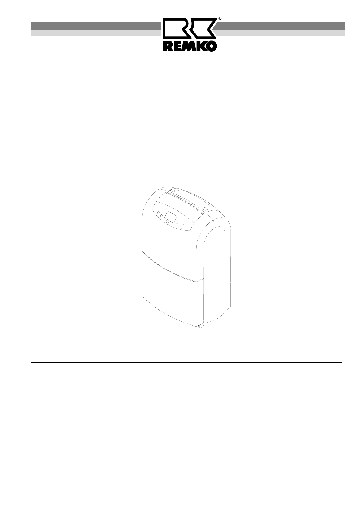
REMKO ETF 220
Portable Air Dehumidifier
Operation
Technology
Spare Parts
Edition GB – P04
REMKO – powerful like a bear.
Page 2

Page 3
Operating Instructions
Read these instructions carefully before setting up/operating the unit!
Our guarantee becomes null and void if the unit is used, set up or maintained improperly, or if
modifications are made to the supplied unit without our prior consent.
Subject to alterations.
Portable air dehumidifier
REMKO ETF 220
Contents Page
Air Dehumidification 4
Safety Instructions 6
Description of the Unit 6
Setup 7
Display 7
Operation 8
Initial Operation 8
Timer mode 10
Shutting Down the Unit 10
Cleaning the Filter 10
Always keep these operating instructions near or on the unit.
Contents Page
Unit Transport 10
Maintenance and Service 11
Troubleshooting 11
Exploded View 12
Spare Part List 13
Technical Data 14
Wiring Diagram 14
Customer Service and Guarantee 14
Maintenance and Service Log 15
G G
3
Page 4
Air Dehumidification
The processes that take place during air dehumidification are based on physical laws. We will try to describe
these in a simplified form to give you a general idea
about the principle of air dehumidification.
The Use of REMKO Air Dehumidifiers
◊ No matter how well doors and windows are insu-
lated, dampness and moisture penetrate even thick
concrete walls.
◊ It can take up to 1 or 2 months for the water used in
the production of concrete, mortar, plaster, etc. to
dry.
◊ The moisture that penetrates brickwork as a result of
flooding is released very slowly.
◊ E.g. this is also the case regarding moisture con-
tained in materials in storage.
The moisture escaping from parts of buildings or materials (water vapour) is absorbed by the ambient air. Consequently the humidity of the air increases which results
in corrosion and in formation of mildew, decay, flaked
off paint and other unwanted damage.
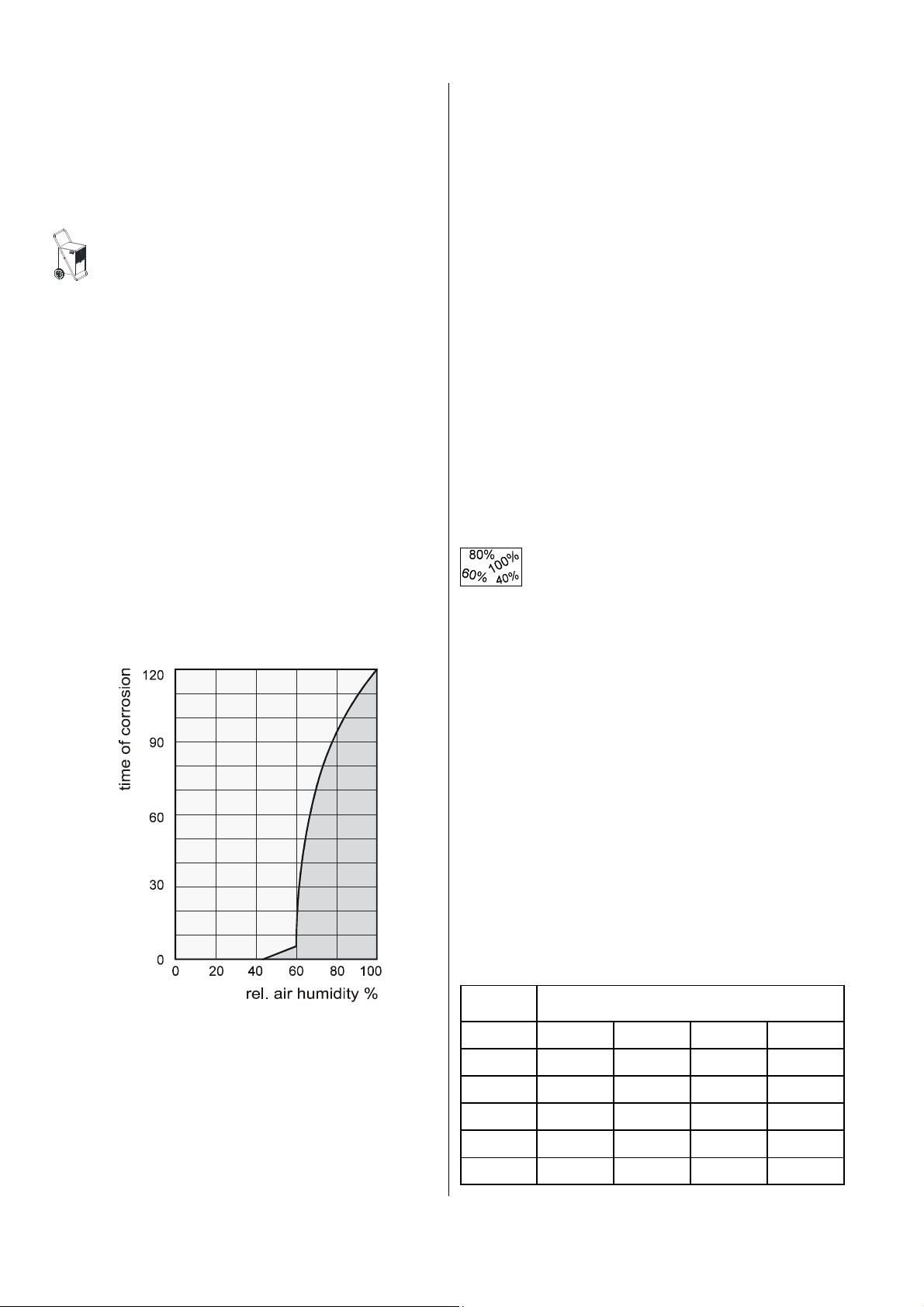
The diagram below is an example of the corrosion rate
of metal at different air humidity levels.
There are two different ways of drying buildings:
1. By heating and exchanging the air:
The ambient air is heated to absorb moisture and ex-
pelled to the outside. However, the total generated
energy is lost with the expelled humid air.
2. By dehumidifying:
The humid air in the closed room is continuously de-
humidified based on the principle of condensation.
With respect to energy consumption, dehumidification
offers one important advantage:
Energy is only needed for the existing room volume.
The mechanical heat released during the dehumidification process increases the room temperature slightly.
When used properly, the air dehumidifier consumes
only approx. 25 % of the energy to be supplied according to the “heating and ventilation” principle.
Relative Air Humidity
Ambient air is a gas mixture which always contains a
certain percentage of water as water vapour.
This percentage of water is indicated in g per kg of dry
air (absolute water content).
1 m³ of air weighs approx. 1.2 kg at 20° C.
Depending on the temperature, each kg of air can only
absorb a defined quantity of water vapour. When this
quantity has been absorbed, the air is “saturated” and
has a relative humidity of 100 %.
Relative air humidity is defined as the ratio between the
percentage of water vapour contained in the air at the
moment in question and the maximum possible percentage of the water vapour when the temperature is
the same.
The capacity of air to absorb water vapour increases
when the temperature rises. This means that the maximum possible (= absolute) water content is increased
as the temperature increases.
As you can see, the corrosion rate is insignificant at a
relative air humidity of less than 50 % and at a humidity
rate of less than 40 %, it can even be ignored. When
the relative humidity exceeds 60 %, the corrosion rate
increases considerably.
This limit for damage caused by humidity also applies
for many other materials, such as powdery substances,
packing materials, wood, and electronic devices.
4
Temp. °C
-5 1.3 1.9 2.6 3.3
+10 3.8 5.6 7.5 9.4
+15 5.1 7.7 10.2 12.8
+20 6.9 10.4 13.8 17.3
+25 9.2 13.8 18.4 23.0
+30 12.9 18.2 24.3 30.3
Water vapour content in g/m³ at an air humidity of
40% 60% 80% 100%
Page 5
Water Vapour Condensation
+
+
The maximum possible amount of water vapour that
can be absorbed becomes higher when the air is
heated, but the water vapour content remains unchanged and consequently the relative air humidity is
reduced.
However, when the air is cooled, the maximum possible amount of water vapour that can be absorbed is
continuously reduced although the water vapour quantity contained in the air remains unchanged and consequently the relative air humidity rises.
When the air is further cooled, the absorption capacity
with respect to the maximum amount of water vapour
possible is continuously reduced until it is equivalent to
the water vapour content. This is the dew point temperature.
If the air is cooled below the dew point, the water vapour
content will be higher than the maximum amount of water vapour possible.
Water vapour is expelled.
It condenses, is converted into water and thus extracted
from the air.
Steamed up window panes in winter or
steamed up bottles containing cold drinks are
typical examples of condensation.
The higher the relative air humidity is, the
higher the dew point temperature is and consequently the easier it is for the temperatures
to fall below the dew point.
Drying Materials
Building materials/buildings can absorb considerable
amounts of water; e.g. bricks 90-190 l/m³, heavy concrete 140-190 l/m³, calcareous sandstone 180-270 l/m³.
Damp materials such as brickwork dry as described below:
◊ The moisture contained in the material
flows from the inside to the surface
◊ Evaporation takes place on the sur-
face = water vapour is absorbed by the
ambient air.
◊ The air augmented with water vapour continuously
circulates through the REMKO air dehumidifier. It is
dehumidified and leaves the unit in a slightly warm
state to absorb water vapour again.
◊ This allows the moisture contained in the material to
be continuously reduced; the material becomes dry.
The resulting condensation is collected in the device and drained.
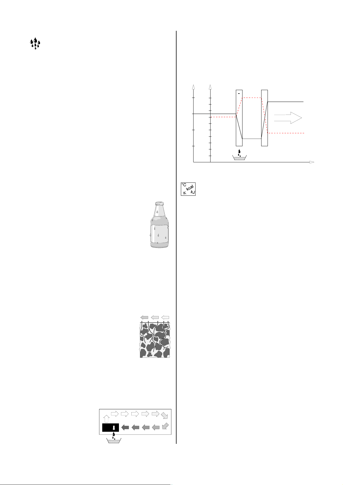
The air current is cooled on its way through/via the
evaporator until its temperature falls below the dew
point. The water vapour condenses, is collected in a
condensation tray and drained.
°C
% r.F.
30
100
90
25
20
15
80
70
60
50
40
30
20
10
-
condenser evaporator
air-temperature
air direction
humidity
time
Condensation Heat
The energy transferred from the condenser to the air
consists of:
◊ The heat that was previously extracted in the evapo-
rator.
◊ The electric operating power.
◊ The condensation heat released by liquefying water
vapour.
When the liquid is converted into a gaseous state, energy must flow back. This energy is called evaporation
heat. It does not cause the temperature to rise but is
used for the conversion from the liquid to the gaseous
state. Conversely, energy is released when gas is liquefied, and this energy is called condensation heat.
The energy produced from evaporation and condensation heat is identical.
For water this is 2250 kJ / kg ( 4.18 kJ = 1kcal )
This shows that a relatively high amount of energy is re-
leased through water vapour condensation.
If the humidity to be condensed is not generated by
evaporation within the room, but supplied from the outside, e.g. by ventilation, the condensation heat released
thereby contributes to heating the room.
When materials or rooms are to be dried, the heat energy flows in a cycle, i.e. it is consumed during evaporation and released during condensation.
A larger amount of heat energy is generated when supplied air is dehumidified which is expressed as a rise in
temperature.
Generally, the time needed for drying does not depend
on the unit capacity, but is determined by the speed at
which the material or the parts of the building release
the moisture contained in them.
5
Page 6
Safety Instructions
Extensive tests have been conducted on the material,
functionality and quality of this unit before it was
shipped.
Hazards may nevertheless arise if the unit is used by
persons not familiar with its operation or if the unit is not
used for its intended purpose!
Please also make sure to follow these safety instructions.
◊ The unit may not be set up or operated in rooms
susceptible to explosions.
◊ The unit may not be set up and operated in rooms
whose atmosphere is contaminated by oil, sulfur,
chlorine or salt.
◊ The unit must be securely placed in an upright posi-
tion.
◊ The unit may not be exposed to a direct stream of
water.
◊ The air intake and outlet openings may never be
blocked.
◊ The air intake side must always be free of dirt and
loose objects.
◊ Never insert foreign objects into the unit.
◊ The unit may not be covered or transported during
operation.
◊ The electrical cables outside the unit must be pro-
tected from being damaged (e.g. by animals).
◊ Make sure that extension cables are suitable in
terms of capacity, length and intended use.
◊ The unit may only be transported in an upright posi-
tion, the condensation collector must be emptied
each time before the unit is moved.
◊ The unit may not be operated for a different purpose
or other than as described in this manual.
In cases of non-compliance, we assume no liability
and the guarantee becomes null and void.
Work on the cooling system and the electrical system may only be performed by authorised person-
G
nel!
Description of the Unit
The unit has been designed for automatic, universal,
smooth air dehumidification. Its compact dimensions
make it easy to transport and set up.
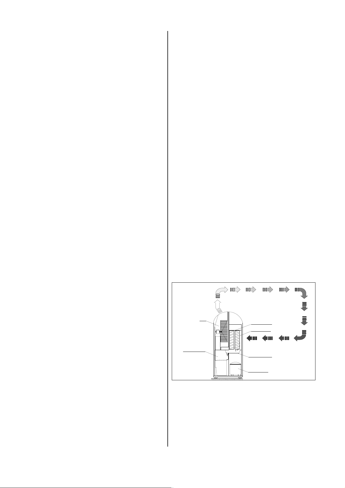
The unit works on the principle of condensation. It is
equipped with a closed-loop cooling system, a quiet fan
requiring little maintenance and a power cord with plug.
The unit has a control panel with an LCD display to control the functions. The unit can be set to automatically
switch on and off at specific times via the timer function.
A fully-automatic control, the condensation collector with
integrated overflow prevention mechanism and the connection adapter for direct drainage of condensation ensure that the unit run smoothly in smooth operation.
The unit meet the basic safety and health requirements
found in the relevant EU regulations. It is safe and easy
to operate.
Unit setup locations
The unit is used in rooms where dry air is a priority to
avoid consequential financial losses (e.g. as a result of
a buildup of mildew).
The unit is primarily used to dry and dehumidify:
◊ Living rooms, bedrooms, showers or basements.
◊ Kitchens, weekend houses, caravans.
And to keep the following dry on an permanent basis:
◊ Storage areas, archives, laboratories.
◊ Bathing, washing, changing rooms, etc.
Function
The unit works on the principle of condensation.
The fan sucks the moist ambient air into the back of the
unit via the air filter, the evaporator and the condenser
located behind the evaporator.
Heat is extracted from the ambient air at the cold
evaporator. The ambient air is cooled until it falls below
the dew point and the water vapour contained in the air
turns into condensation or frost on the evaporator fins.
Dehumidified
air
Fan
Condensation
collector
Condenser
Evaporator
Moist air
Compensation
collector
Compressor
Diagram of how the unit functions
The dehumidified, cooled air is reheated in the con-
denser (heat-exchanger) and then released at a temperature of approximately 5 degrees above room temperature.
This air, which is now drier, is mixed again with the ambient air. The humidity of the air is gradually reduced to
the desired relative humidity through the continuous circulation of ambient air by the unit.
6
Page 7
Depending on the air temperature and the relative humidity, the condensed water drips out steadily or only
during periodic defrosting phases into the collection
tray and then into the condensation collector beneath
it through the integrated drainage lines.
A float regulator flap is installed in the condensation collector that interrupts dehumidification operation via a microswitch when the collector is full.
The unit switches off and the LCD display "Collector full“
lights up. It goes off again when the condensation collector is emptied and replaced. The unit then restarts after a delay of approximately 2 minutes.
For unsupervised, continuous operation of the unit, the
condensation is continuously drained via an external
water hose.
Setup
Follow the instructions below to ensure the to optimum,
economical and safe operation of your unit.
◊ The unit must be securely placed in an upright posi-
tion so that condensation can drain freely into the
condensation collector.
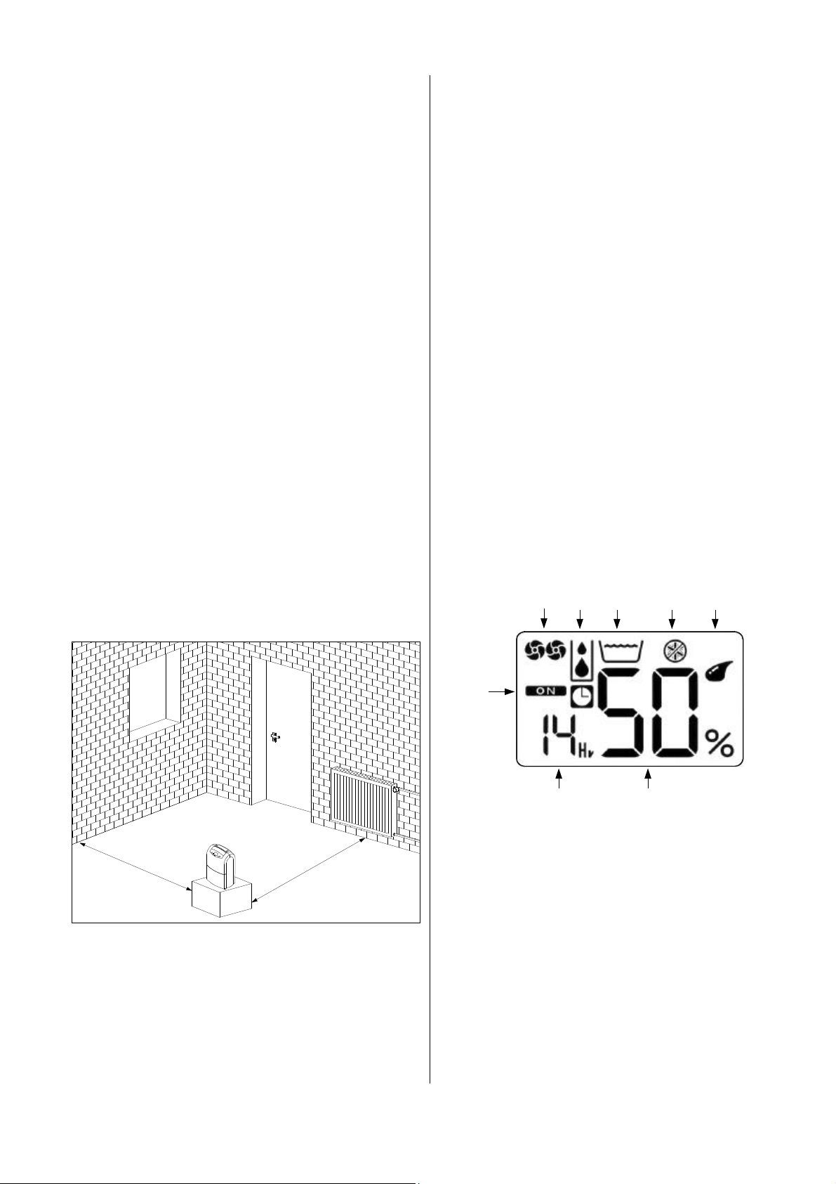
◊ If possible, place the unit in the middle of the room to
ensure optimum air circulation.
◊ Maintain a minimum distance of 50 cm to walls.
◊ If the unit is in operation in a dusty environment, the
appropriate service and maintenance measures are
to be undertaken in accordance with the specific
conditions.
See chapter "Maintenance and Service".
◊ You can improve the air circulation if you set up the
unit at a height of approximately 1 m.
Important information about the electrical connection
◊ The electrical connection of the unit is to be carried
out in accordance with DIN VDE 0100, Part 704 to
electrical supply points with residual current circuit
breakers.
◊ When the unit is set up in wet areas such as in bath-
rooms or kitchens, the unit must be equipped by the
customer with a residual current circuit breaker that
meets regulations.
Display
The unit has an LCD display which shows the relative
humidity of the room, the operating mode and other important information.
1
2 3 4 5
Fenster
geschlossen
halten
W
a
n
d
a
b
s
t
a
n
d
m
i
n
d
.
0
,
5
m
b
A
a
Tür
geschlossen
halten
d
n
a
t
s
e
r
e
d
n
r
e
d
o
n
n
r
e
t
e
l
p
a
r
h
ö
k
n
z
e
i
l
l
e
e
H
u
q
u
z
e
m
r
ä
W
n
◊ Make sure that the air can flow freely into the back of
the unit and out of the upper air flap.
◊ Do not place the unit in the direct vicinity of radiators
or other heat sources.
◊ Keep the room to be dried or dehumidified closed so
that air from the surroundings cannot get in.
◊ Keep windows and doors closed and avoid entering
and leaving the room frequently.
6
7 8
1 "Fan speed" display
2 "Dehumidification" display
3 "Collector full" display
4 "Defrost mode" display
5 "Operating mode" display
AUTOMATIC 45% - 55% rel. humidity
COMFORT 55% - 65% rel. humidity
MAXIMUM
VENTILATION
6 "Timer" display
7 "Elapsed time" display
8 "Relative humidity" display measured on the unit
sensor.
7
Page 8
Operation
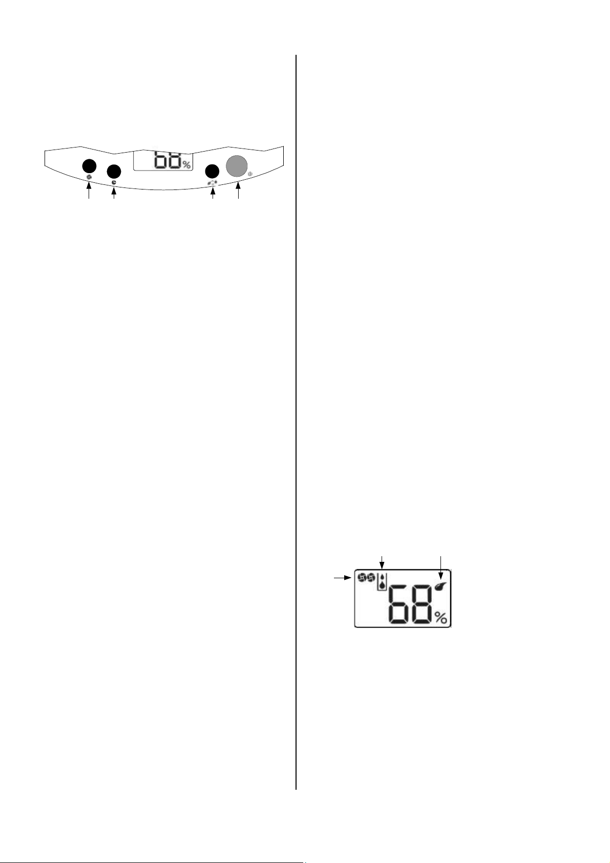
Control panel
The display and the buttons for operating the unit are located on the control panel.
VENTILATION
1 4 3 2
1 "On/Off“ button
You can use this button to switch the unit on or off.
2 "Fan speed“ button
You can use this button to select one of the two fan
speeds in the Comfort and Maximum operating
modes. Each time the button is pressed, the fan
switches to a different speed.
3 "Timer“ button
You can use this button to program the unit to switch
on and off automatically.
4 "Operating mode“ button
You can use this button to switch the unit to the operating mode you want.
Initial Operation
Prior to initial operation or to meet local requirements,
the air intake and outlet openings must be inspected for
foreign bodies and the air intake filter for dirt.
Blocked or dirty grilles and filters must be cleaned immediately. See chapter “Maintenance and Service“.
Important instructions prior to operation
◊ Extension cords must be sufficiently thick.
◊ Extension cords can only be used if they are com-
pletely extended or rolled up!
◊ The condensation collector must be inserted prop-
erly.
Otherwise the unit does not work!
At room temperatures below 10 °C and a relative
humidity of less than 40 %, we no longer guaran-
G
tee that the unit performs efficiently.
Initial operation of the unit
1. Insert the power plug into a correctly fused plug
socket.
230V / 1~ / 50 Hz / 10 A.
Unit operating modes
The unit has four operating modes:
1. AUTOMATIC 45%-55%
In this operating mode, the unit dehumidifies for one
hour at a low fan speed regardless of the humidity
measured in the room. After this time period has
elapsed, the unit dehumidifies automatically. The required fan speed is set automatically by the unit.
2. COMFORT 55%-65%
If the integrated sensor measures a humidity level of
more than 65%, the unit dehumidifies.
If the humidity falls below 55%, the unit no longer de-
humidifies. If the humidity rises above 65%, the unit
dehumidifies again. The fan speed can be set as
necessary.
3. MAXIMUM
In this operating mode, the unit dehumidifies continu-
ously after being switched on regardless of the humidity measured in the room. The fan speed can be
set as necessary.
4. VENTILATION
In this operating mode, the air in the room is circu-
lated. The unit does not dehumidify. The lowest fan
speed is set.
The fan remains in continuous operation until the
unit switches off to ensure that the integrated sen-
G
sor can always correctly measure the humidity.
2. Open the air flap on the top of the unit.
3. Switch the unit on with the “On/Off” button.
Each time a button is pressed, the display lights up
for approximately 10 seconds.
4. Select the operating mode you want by pressing the
“Operating mode” button several times.
The Symbol A only appears on the display when the
compressor is working and the unit is dehumidifying.
5. Make sure that the Symbol B indicates the set operating mode.
A
C
6. Select one of the two fans speeds with the “Fan
speed” button in the COMFORT and MAXIMUM operating modes.
In the VENTILATION operating mode, the fan generally rotates at a lower speed, in the AUTOMATIC operating mode, the speed is automatically set depending on the humidity.
7. Make sure that the Symbol C displays the set fan
speed.
One symbol on the display = low speed
Two symbols = high speed.
B
AUTOMATIC 45%-55%
COMFORT 55%-65%
MAXIMUM
VENTILATION
8
Page 9
Instructions for unit operation
Automatic defrost
◊ After being switched on, the unit functions fully auto-
matically until it is switched off by a control mechanism activated by the float when the condensation
collector is full.
◊ If, during operation, the power supply is interrupted,
the unit does not switch on again automatically after
power has been restored. If a timer function was programmed, it is deleted.
◊ If the unit is in operation with an external condensa-
tion hose in continuous operation, please read the
applicable section on this page.
◊ If the unit was switched off manually by the “On/Off”
button or by the float mechanism, the compressor
switches on again only after a delay of approximately
5 minutes.
This safety mechanism prevents the compressor
from overloading.
◊ The fan remains in continuous operation until the
unit switches off to ensure that the integrated sensor
can always correctly measure the humidity.
Information on dehumidification performance
The dehumidification performance is dependent only on
the spatial composition of the room, the room temperature, the relative humidity and following the instructions
in the chapter entitled “Setup”.
The maximum dehumidification performance is
achieved by opening the air flap completely.
The higher the room temperature and the relative humidity, the greater the dehumidification performance is.
For use in residences, a humidity level of approximately
45 to 60 % is sufficient while a humidity level of 40 to 45
% may not be exceeded in storage areas, archives, etc.
The humidity contained in the ambient air condenses
when cooled and covers the evaporator fins with frost or
ice depending on the air temperature and the relative
humidity. This frost or ice buildup is automatically defrosted from the unit.
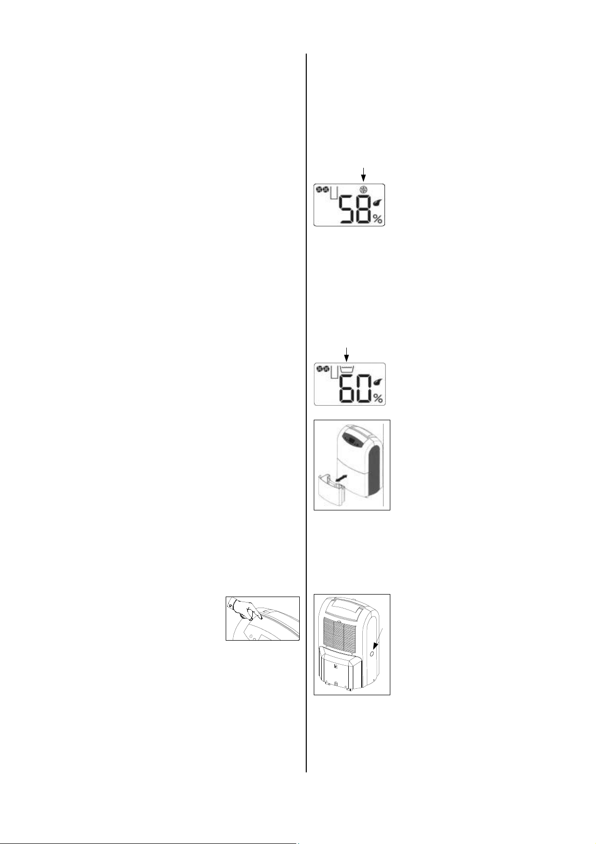
D
Condensation collector
It is necessary to empty the integrated condensation
collector from time to time.
When the collector is full, the dehumidification mode is
interrupted and the Symbol E appears on the display.
E
The integrated automatic defrost system switches the defrost cycle on
when necessary.
During the defrost phase, the dehumidification mode is briefly interrupted.
The Symbol D appears on the display.
1. Carefully pull out the collector towards you.
2. Pour the condensation into a
drain.
3. Clean the collector with a clean
towel.
4. Carefully reinsert the collector
into the unit.
5. Keep in mind that the unit only
starts when the collector has
been correctly inserted.
The Symbol E disappears from
the display and the unit begins to
work again fully automatically.
Setting the air outlet direction
The dehumidified ambient air is expelled from the top of
the unit. The adjustable air flap can be used to change
the direction of the air being expelled.
1. To open the air flap, press on the
rear surface.
The front side opens upwards. You
can adjust the direction of the air
any way you want.
2. If possible, create a flow of air going upwards by
opening the flap completely.
3. Make sure that nothing is blocking the air from being
expelled.
This is the only way to guarantee optimum unit op-
eration.
4. Make sure that sensitive objects, such as plants in
the room, are not directly in the path of the expelled
air.
Continuous operation with an external condensation hose.
The unit must be equipped with a connection adapter on
the left side. A standard 1/2" water hose can be connected here.
1. Using a suitable tool, break the
cover F of the connection
F
When the unit is in continuous operation, the condens ation can now be directed, for example, to a drain at a
lower level.
Make sure that the hose is placed at an incline to
the drain so that the condensation is not blocked
G
from flowing out of the condensation collector!
adapter from the unit wall.
Only necessary for the initial connection.
2. Connect a drainage hose that is
sufficiently long to the connection
adapter.
9
Page 10
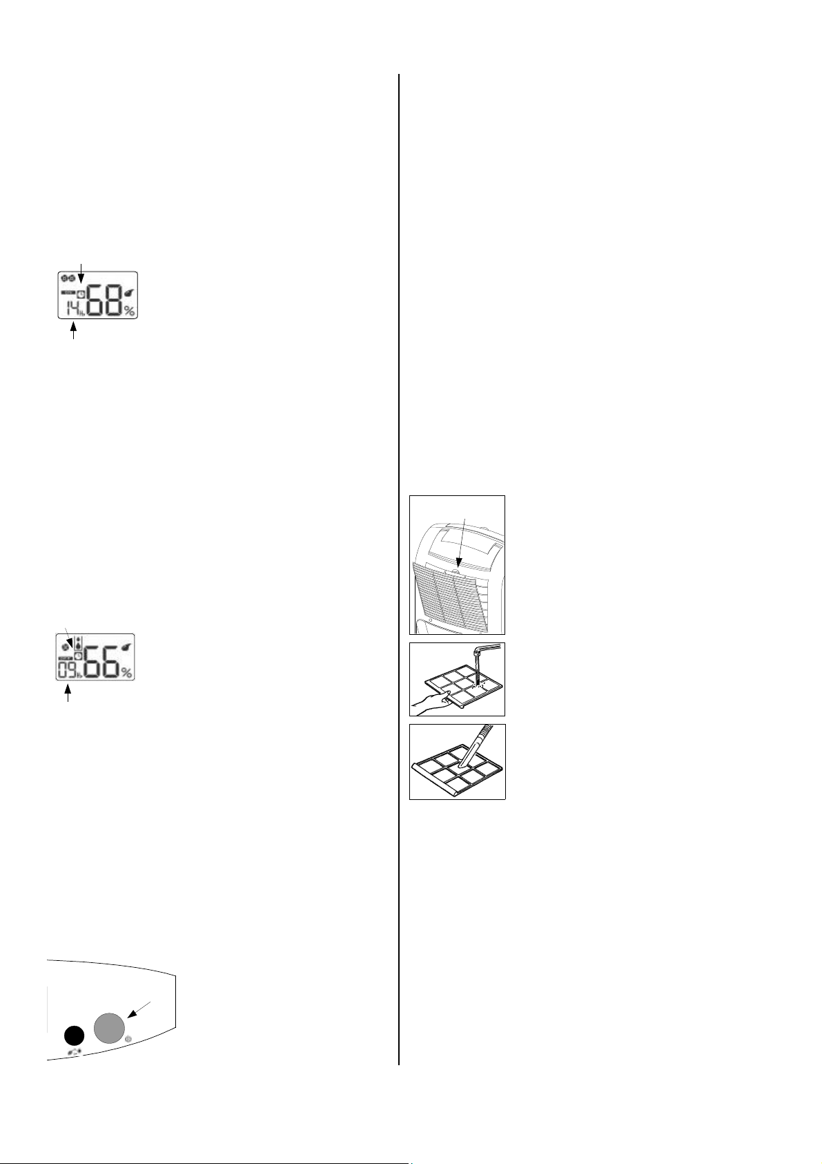
Timer mode
The “Timer” button (see page 8) is used to activate
operation of the unit at a programmed time. The unit
switches on or off after the preset time has elapsed.
Timer mode is indicated on the display by a clock
symbol.
Switching the unit on automatically
4
5
3. Select the operating mode you want by pressing the
“Operating mode” button several times.
4. Select one of the two fans speeds with the “Fan
speed” button in the COMFORT and MAXIMUM operating modes.
5. Keep in mind that the unit automatically switches on
with the selected settings after the set time has
elapsed.
The Symbol 4 and “On” disappear from the display.
6. Press the “On/Off” button if you want to switch on the
unit before the set time has elapsed.
Switching the unit off automatically
4
5
3. Keep in mind that the unit automatically switches off
after the set time has elapsed.
4. Press the “On/Off” button if you want to switch off the
unit before the set time has elapsed.
1. While the unit is switched off,
press the “Timer” button.
The Symbol 4 and "On" appear on
the display.
2. Press the “Timer” button until the
desired amount of time 5 appears
on the display in hours.
1. While the unit is switched on,
press the “Timer” button.
The Symbol 4 and “Off” appear on
the display.
2. Press the “Timer” button until the
desired amount of time 5 appears
on the display in hours.
Prior to longer periods of non-operation
1. Unplug the power cord.
2. Empty the condensation collector and dry it with a
clean towel.
Watch out for condensation that drips out.
3. Follow the instructions for cleaning the air intake filter.
4. To prevent dust from getting inside the unit, protect it
with, for example, a plastic cover.
5. Store the unit in an upright position in a location protected from dust and direct sunlight.
Cleaning the filter
To prevent damage to the unit, it is equipped with an air
intake filter.
The air intake filter must be inspected as necessary,
however, at least every two weeks, and cleaned if required to prevent its performance from suffering or
problems with the unit.
G
The unit may never be operated without the air intake filter!
G
1. Switch the unit off by pressing the
“On/Off” button.
2. Reach into the opening G and pull
the air intake filter out of the unit.
3. Clean the air intake filter with
warm water or with a vacuum
cleaner.
4. Remove heavy dirt by rinsing the
unit in a soapy solution at a maximum temperature of 40 °C.
Then rinse with clean water.
5. Keep in mind that the air intake filter may not be damaged and must
be completely dry before being replaced to prevent damage to the
unit.
Shutting Down the Unit
AUTOMATIC 45%-55%
COMFORT 55%-65%
MAXIMUM
VENTILATION
10
D
Switch the unit off by pressing the
“On/Off” button D.
Unit Transport
The unit is equipped with wheels and a handle to make
it easy to transport.
◊ Prior to moving the unit, switch the unit off and un-
plug it.
◊ Then empty the condensation collector.
Watch out for condensation that drips out.
◊ Do not use the power cord to pull the unit.
Page 11

Maintenance and Service
Regular maintenance and observance of some basic
principles are required to ensure a long service life and
to keep the unit functioning properly.
However, the unit should be inspected at least once a
year and thoroughly cleaned after long periods of use.
All movable parts have a permanent lubrication that requires little maintenance. The entire cooling system is a
low-maintenance, closed-loop system and may only be
serviced by authorised service centres.
Before performing any work on the unit, make sure
to unplug power cord!
G
◊ Keep the unit free of dust and other deposits.
◊ Use only a dry or slightly moist towel to clean the
unit.
Do not expose it to a direct stream of water.
◊ Do not use abrasive cleaning agents or cleaning
products containing solvents; only use suitable
cleaning products even when the unit is extremely
dirty.
◊ Check the air intake filter for dirt on a regular basis.
Clean or replace if necessary.
Work on the cooling system and the electrical system may only be performed by authorised person-
G
nel!
Cleaning the condenser and evaporator
The unit housing must be open to perform work on
these components; this work may only be performed by
authorised service centres!
◊ Clean the condenser and the evaporator either by
blowing air into the unit or with a vacuum cleaner or
soft brush.
Do not expose it to a direct stream of water.
◊ Keep in mind that the fins are easy to damage or
bend.
◊ Carefully clean the inner surfaces of the unit, the con-
densation tray with hose connection, the fan and the
fan housing.
◊ Reassemble all of the disassembled parts properly.
◊ Perform a functional test and conduct an electrical
safety check!
Troubleshooting
The unit was tested repeatedly during production to ensure that it is working properly.
However, should problems occur, refer to the following
list.
The unit does not start:
◊ Check the connection to the power supply.
230V / 1~ / 50 Hz.
◊ Check the power fuse installed by the customer.
10 A.
◊ Check the power plug for damage.
The unit starts but no condensation forms:
◊ Check that the condensation collector has been in-
serted properly and is not full.
“Collector full” may not appear on the display.
◊ Check that the microswitch of the condensation col-
lector is working.
◊ Check the room temperature.
The operating range of the unit is between 6 and 32
°C.
◊ Check the humidity.
Minimum 40 % relative humidity.
◊ Check the set operating mode.
The humidity in the setup room must be more than the
humidity of the selected range.
◊ Check the air intake filter for dirt.
Clean or replace if necessary.
◊ Check the exchanger fins for dirt.
To conduct this test, the unit must be open; it may
only be performed by an authorised service centre.
Before performing any work on the unit, make sure
to unplug power cord.
G
The unit is loud or vibrates, condensation comes
out:
◊ Make sure that the unit is in an upright position on a
flat surface.
◊ Check the condensation collector and the connection
adapter for dirt.
To perform this test, the unit must be open; it may
only be performed by an authorised service centre.
Import information on recycling!
The unit is operated with the environmentally-friendly refrigerant R134 a which does not harm the ozone layer.
The refrigerant/oil mixture in the unit must be disposed
of properly in accordance with general regulations and
local requirements.
If, after performing these checks, the unit still does not
work properly, please notify an authorised service centre.
Work on the cooling system and the electrical system may only be performed by authorised person-
G
nel!
11
Page 12
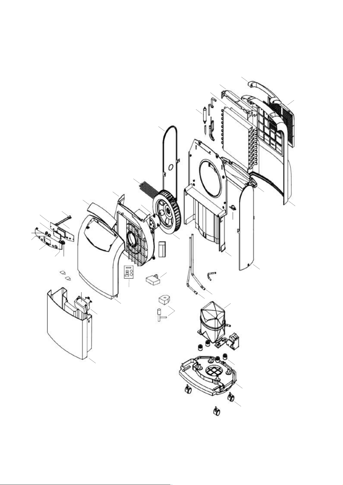
Exploded View
41
19
11
46
17
38
25
33
34
29
28
37
35
30
36
31
44
48
47
20
42
32
21
27
51
22
5
10
40
9
8
39
6
3
12
49
We reserve the right to make changes to dimensions and design in the interest of technical progress.
4
1
2
Page 13

Spare Part List
No. Description Ref. No.
1 Base plate 1103620
2 Transport roller 1103621
3 Compressor 1103622
4 Vibration absorber 1103623
5 Suction pipe 1103624
6 High-pressure line 1103625
8 Center wall 1103626
9 Microswitch 1103627
10 Collection tray 1103628
11 Heat-exchanger-package cpl. 1103629
11a Evaporator 1103630
11b Condenser 1103631
17 Dryer 1103632
19 Cover, top 1103633
20 Fan housing 1103634
21 Fan motor 1103635
22 Fan wheel 1103636
25 Protective grille 1103637
27 Capacitor 1103638
28 Display 1103639
29 Circuit board, control panel 1103640
30 Circuit board, humidity sensor 1103641
31 Anti-frost sensor 1103642
32 PCB with control 1103643
33 Button, fan speed 1103644
34 Button, timer 1103645
35 Button, operating mode 1103646
36 Button, on/off 1103647
37 Control panel 1103648
38 Side plate, right 1103649
39 Side plate, left 1103650
40 Rear wall 1103651
41 Transport handle 1103652
42 Front wall 1103653
44 Air directing flap 1103654
46 Air intake grill with filter 1103655
47 Float housing 1103656
48 Float, styrofoam 1103657
49 Condensation collector 1103658
51 Magnetic valve, cpl. 1103659
Not shown Electrical cable incl. plug 1103660
When ordering spare parts please indicate ref. no. and machine no. (see type plate).
13
Page 14
M1
CN1
CN2
CN3
CN1-A
MSSPFS
rtg
ewsbl
rtblbl
ws
Technical Data
Customer Service and
Series ETF 220
Operating range temperature °C 6 - 32
Operating range humidity % r. h. 40-100
Dehumidification capacity max. l/day 22
at 30 °C / 80 % r.h. l/day 20.6
Air capacity, min./max. m³/h 150/190
Refrigerant R 134a
Refrigerant amount g 340
Electrical connection V 230/1~
Frequency Hz 50
Rated current max. A 3.4
Power consumption max. W 620
Fuse protection (supplied) A 10
Sound pressure level min./max. L
Dimensions:
Depth mm 315
Width mm 390
Height mm 620
Weight kg 21
1) Noise measurement DIN 45635 - 01 - KL 3
pA 1m
1)
dB (A) 42/46
Guarantee
For the guarantee to be valid, the purchaser or his customer must completely fill out the "guarantee certificate"
enclosed with all units and send it back to REMKO GmbH
& Co. KG.
The units are repeatedly tested at the production site to
ensure that they are working properly. If a malfunction
occurs that cannot be eliminated by the operating personnel, please contact your dealer or contact person.
Operation/handling which does not comply with
these instructions is prohibited!
In cases of non-compliance, we assume no liability
G
and the guarantee becomes null and void.
Proper Use
The units have been designed and equipped exclusively
for dehumidification purposes.
The manufacturer assumes no liability for damage resulting from non-compliance with manufacturer specifications and legal requirements, or if modifications are
made to the units.
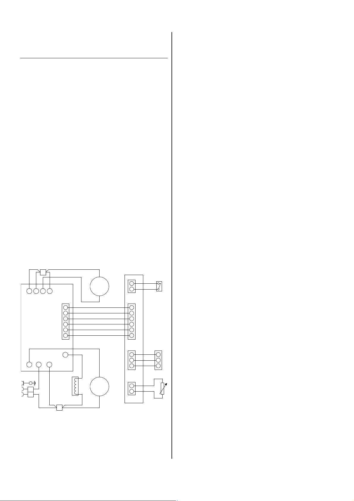
Wiring Diagram
M2
HI
ws
brws
NS
FS Frost protection sensor MS Microswitch
MV
M1 Compressor motor NS Power supply
M2 Fan motor SP Sensor board
MV Magnetic valve
14
Page 15
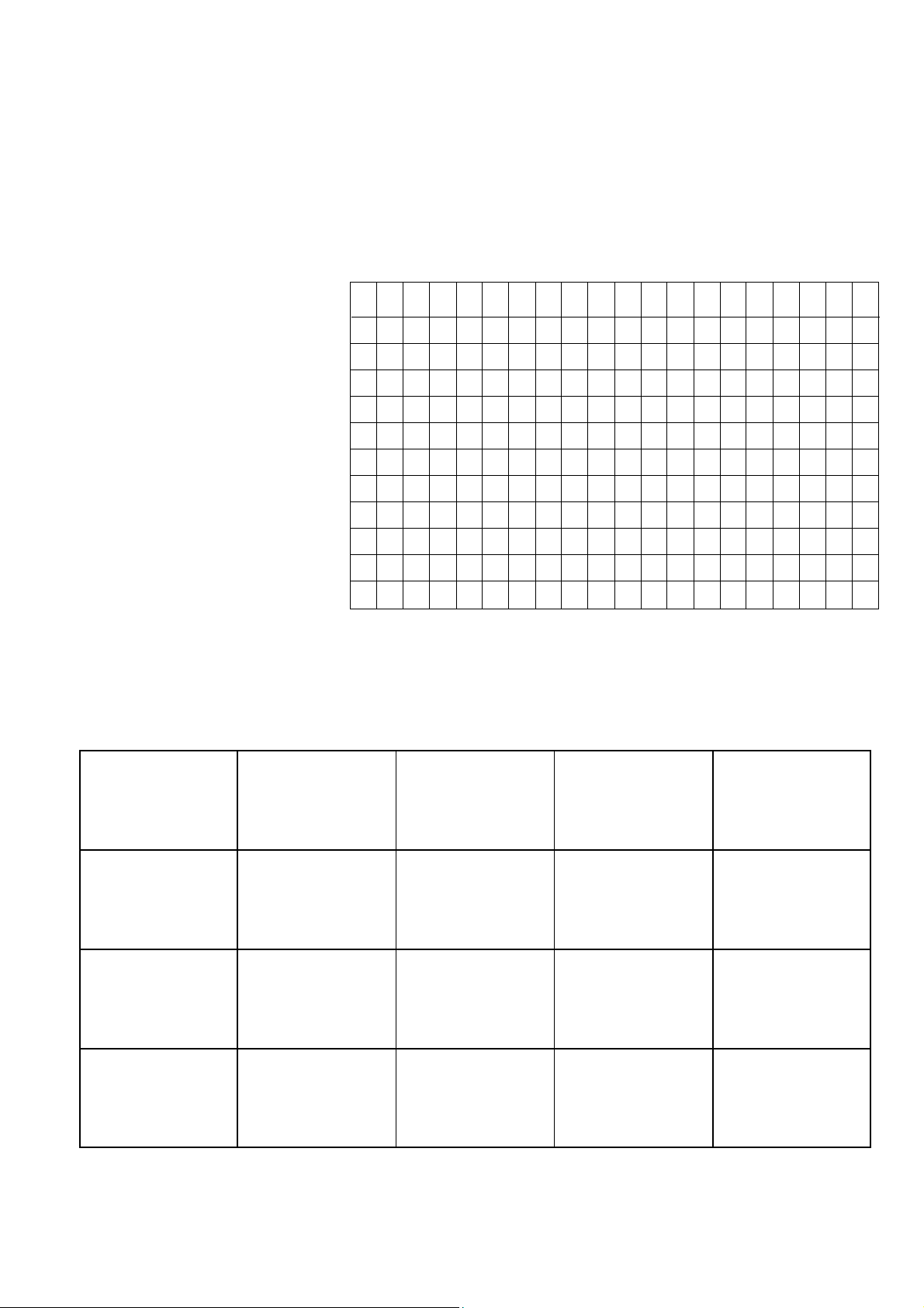
Maintenance and Service Log
Model: ................................ Model No.: ......................................
1 2 3 4 5 6 7 8 9 10 11 12 13 14 15 16 17 18 19 20
Clean device -surfaceClean device -interiorClean condenser
Clean evaporator
Clean fan blade
Clean/replace dust filter
Check protection guards
Check device for damage
Check all fixing screws
Electric safety-inspections
Test run
Remarks: ......................................................................................................................................................................
......................................................................................................................................................................................
1. Date: ...................... 2. Date: ...................... 3. Date: ...................... 4. Date: ...................... 5. Date: ......................
.................................. .................................. .................................. .................................. ..................................
Signature Signature Signature Signature Signature
6. Date: ...................... 7. Date: ...................... 8. Date: ...................... 9. Date: ...................... 10. Date: ....................
.................................. .................................. .................................. .................................. ..................................
Signature Signature Signature Signature Signature
11. Date: .................... 12. Date: .................... 13. Date: .................... 14. Date: .................... 15. Date: ....................
.................................. .................................. .................................. .................................. ..................................
Signature Signature Signature Signature Signature
16. Date: .................... 17. Date: .................... 18. Date: .................... 19. Date: .................... 20. Date: ....................
.................................. .................................. .................................. .................................. ..................................
Signature Signature Signature Signature Signature
The unit must be maintained according to legal regulations by authorised personnel only!
15
Page 16

REMKO GmbH & Co. KG
Klima- und Wärmetechnik
D-32791 Lage • Im Seelenkamp 12
D-32777 Lage • Postfach 1827
Telefon (0 52 32) 606 - 0
Telefax (0 52 32) 606260
E-Mail: [email protected]
Internet: www.remko.de
 Loading...