

Page 1
REMKO
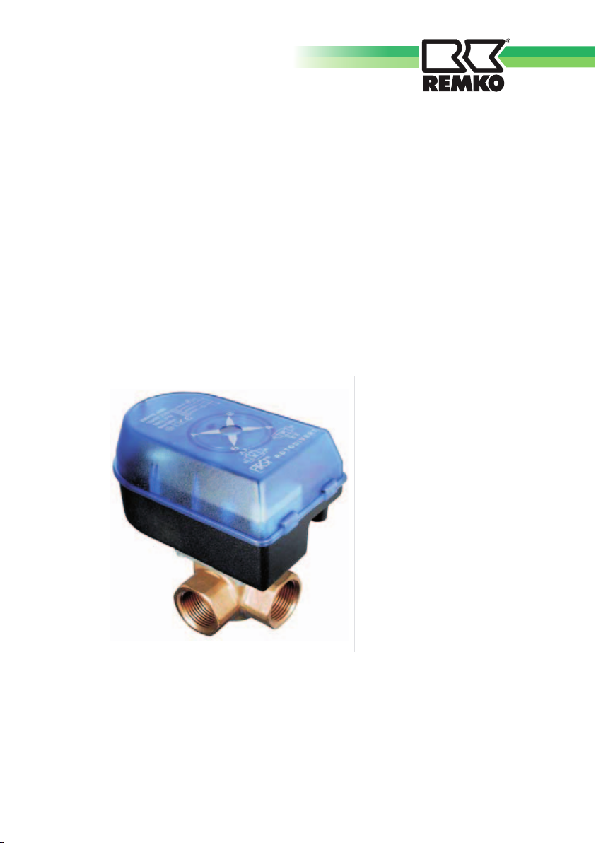
Rotodivert - Umschaltventil
Typ EMV 110../ F3L.. -
1/2 1/4
” ”
1 L-Durchfluß
Ro todiver t-EM V..- F3L
Das Rotodivert 110.F3L von Antriebs Messing-Umschalt
s zB. ie Umschaltung geschlossenen Heizungs , von ung auf Brauchwas serladung vorgesehen,
oder anderer alternativer Energiequellen, zB, für Umschaltung von Öl-Gaskessel auf Feststoff-Kessel,
Der Drehschieber ist mit austauschbaren, glykol-beständigenO-Ringen abgedichtet.
ist eine Kompaktausführung motor miteinem ventil.
E ist für d in ystemen Heiz
Es wird die Montage des Rotodivert in den Rücklauf des Heizsystems vorgeschlagen.
3-WAY SWITCHING VALVE DN 32
Operation · Technology
Edition GB - W08
Page 2

REMKO 3-WAY SWITCHING VALVE DN32
Safety notes
Carefully read the operating instruction
before placing the equipment in service.
It contains useful tips and notes
such as hazard warnings to prevent
injury and material damage. Failure to
follow the directions in this manual can
result in endangerment to persons, the
environment and the equipment itself
and will void any claims for liability.
■ Keep this manual in the vicinity of the
unit.
■ The unit should be set up and
installed only by qualified personnel.
■ The set-up, connection, and operation
of the unit and its components must
be in accordance with the operating
conditions stipulated in this manual
and comply with all applicable local
regulations.
■ Modification of equipment and
components supplied by REMKO
is not permitted and can cause
malfunctions.
■ Equipment and components may not
be operated in areas where there is
an increased risk of damage. Observe
the minimum clearances.
■ The electrical supply is to be adapted
to the requirements of the equipment.
■ The operational safety of equipment
and components is only assured if
they are fully assembled and used as
intended. Safety devices may not be
modified or bypassed.
■ Do not operate equipment or compo-
nents with obvious defects or signs of
damage.
■ The equipment and components
must be kept at a safe distance from
inflammable, explosive, combustible,
aggressive and dirty areas or atmospheres.
■ Installation, repair and maintenance
work may be carried out only by authorised specialists. Visual inspections
and cleaning can be performed by the
operator as long as power is disconnected from the equipment.
■ To preclude any danger from the
equipment, take appropriate hazardprevention measures when performing installation, repair or maintenance
work or cleaning the equipment.
2
Page 3
Environmental protection
and recycling
Disposal of packaging
All products are packed for transport
in environmentally friendly materials.
Make a valuable contribution to reducing
waste and sustaining raw materials.
Only dispose of packaging at approved
collection points.
Disposal of components
Equipment manufacture is
subject to continuous quality
control. Only high-grade
materials are processed, the majority
of which are recyclable. You can also
contribute to environmental protection
by only disposing of components in
accordance with local regulations and
in an environmentally safe manner, e.g.
through authorised disposal and recycling
specialists or at collection points.
Description
The 3-way switching valve controls
the flow of process water or a separate
cooling circuit (four pipe system).
It is comprised of an electrical actuator
and a hydraulic lower section, the actual
valve.
Through its design the brass forged
3-way switching valve allows a
redirection of the medium, almost
entirely independent of the differential
pressure. The rotary valve of the 3-way
switching valve is equipped with
replaceable, glycol-resistant O-rings.
The 3-way switching valve is normally
controlled using an electric actuator.
During the installation work and
especially for the bleeding of the
heating system or for inspection
purposes, the 3-way switching valve
can also be operated manually. For this
purpose the electric actuator must be
removed.
The housing consists of corrosionresistant brass.
The connections have a 5/4" inside
thread on both the inlet and outlet
sides.
Guarantee
The guarantee conditions are listed in the
"General terms and conditions".
Please contact your contractual partner in
the first instance.
This operating manual is a translation of the German original, Version W-08
3
Page 4
REMKO 3-WAY SWITCHING VALVE DN32
Operation
Mode of operation
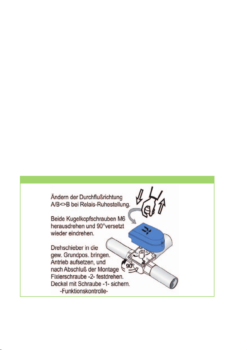
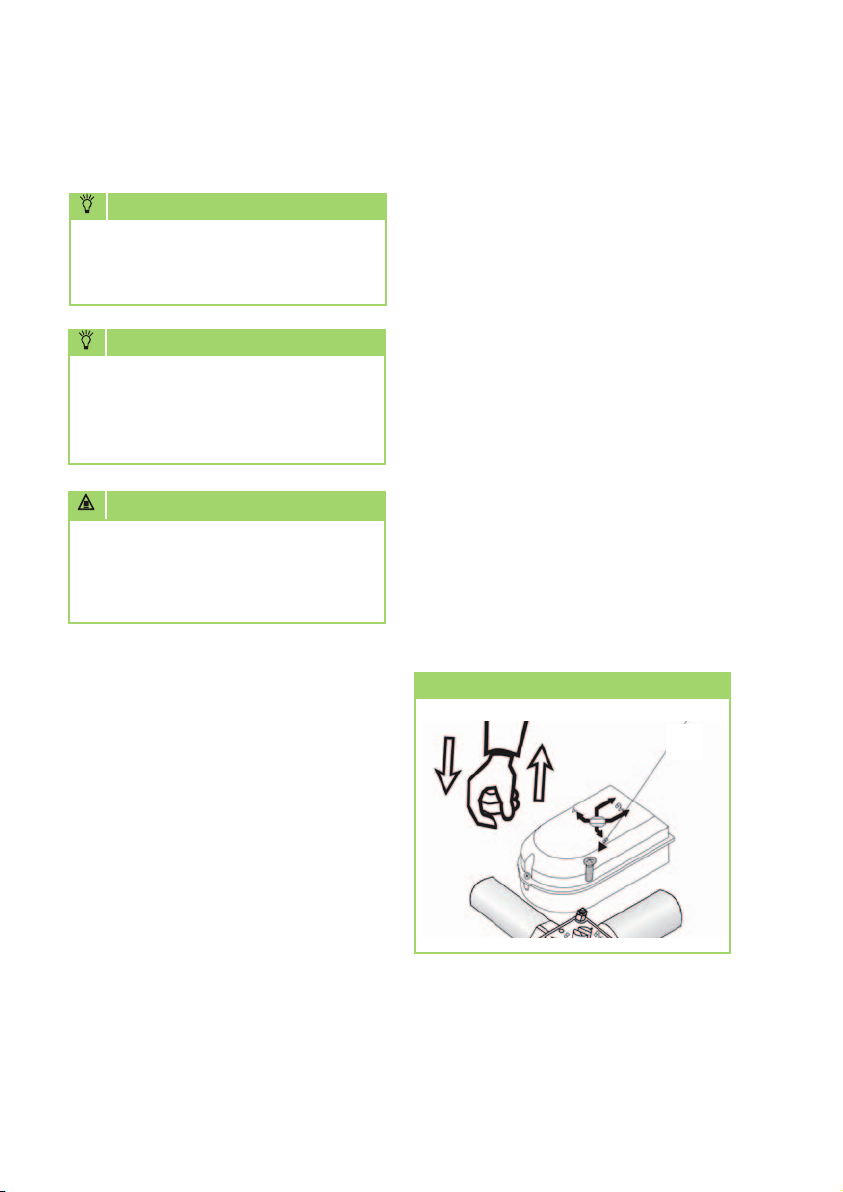
At REMKO the flow direction AB must be
open to B in resting position of the 3-way
switching valve. This corresponds to
the heating flow direction. The correct
position of the axis and the actuator
of the 3-way switching valve must
absolutely be checked before installation.
In the lower figure you can see the
correct position of the axis and the
actuator. If the part which you have on
hand does not match this figure precisely,
proceed according to the modification
instructions (text) of the lower figure.
Flow direction and its change, if applicable
The flow direction of AB to A corresponds
to the hot water charging position or
cooling mode when used as a "cooling"
switching valve in a 4-pipe system.
The reversal between the two flow
directions takes approx. 18 seconds.
4
Page 5
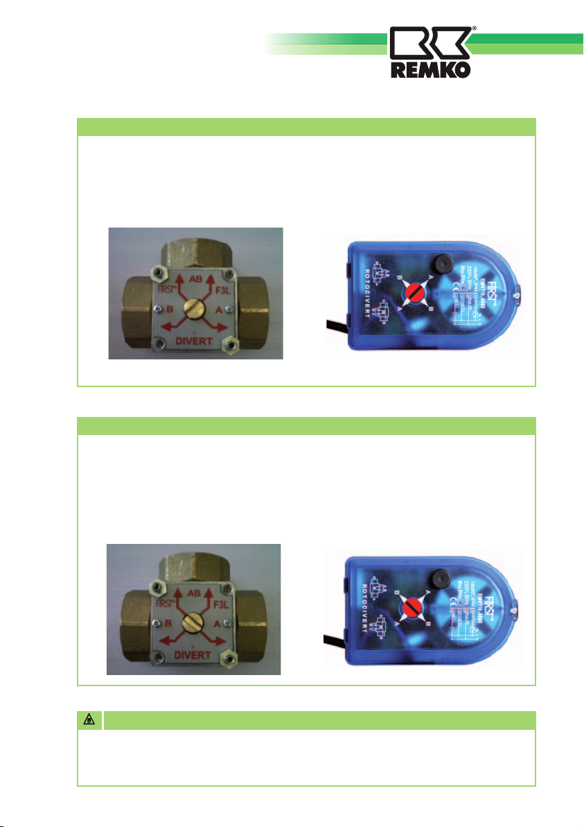
Heating mode flow direction
Initial situation (resting position): Flow direction: AB<->B
Valve in position AB<->B Actuator in position A<->A
(Heat pump in heating mode) (A for "initial situation")
Hot water charging mode or cooling mode flow direction
... after actuation: Flow direction: AB<->A
Valve in position AB<->A Actuator in position B<->B
(Heat pump in hot water or (B for "actuated")
in cooling mode)
ATTENTION
Before installation, make sure of the correct position of the valve axis (if necessary,
rotate the axis, indicator plate and spherical head screws 90° in accordance with
the top figure!
5
Page 6
REMKO 3-WAY SWITCHING VALVE DN32
Installation
NOTE
Installation may only be performed
by authorised specialists.
NOTE
Do not use any boiler accessories,
soldering material or wet materials
of a mineral oil basis, mineral oil
or hydrocarbon.
ATTENTION
Pay attention to the flow direction before
installation. (Correct position of the axis
and installation position in accordance
with the REMKO hydraulic diagram.)
Mounting
The installation is basically independent
of the position. However, the actuator
should not be installed "face-down", as
far as possible.
■ Pay attention to the installation
position and the correct position of
the axis of the 4-way switching valve.
■ Only fit the actuator and make
electrical connection to the heat
pump manager after completion of
all hydraulic installation work and
successful leak test.
■ Allow for sufficient space for the
3-way switching valve. In the process,
also plan for sufficient space for the
pipe insulation. That is important on
the one hand for the problem-free
fitting of the actuator and on the
other hand for any later maintenance
work.
Mounting the actuator
2
■ The 3-way switching valve and the
actuator are loosely fit together in the
condition as supplied. At first, leave
the actuator in the package and begin
with the hydraulic installation of the
4-way switching valve.
6
Page 7
Electrical connection
ATTENTION
All electrical installation work is to be
performed by specialty companies.
Disconnect the voltage supply when
connecting the electrical terminals.
Observe the VDE guidelines.
■ Limit switches are integrated in the
actuator of the 3-way switching
valve.
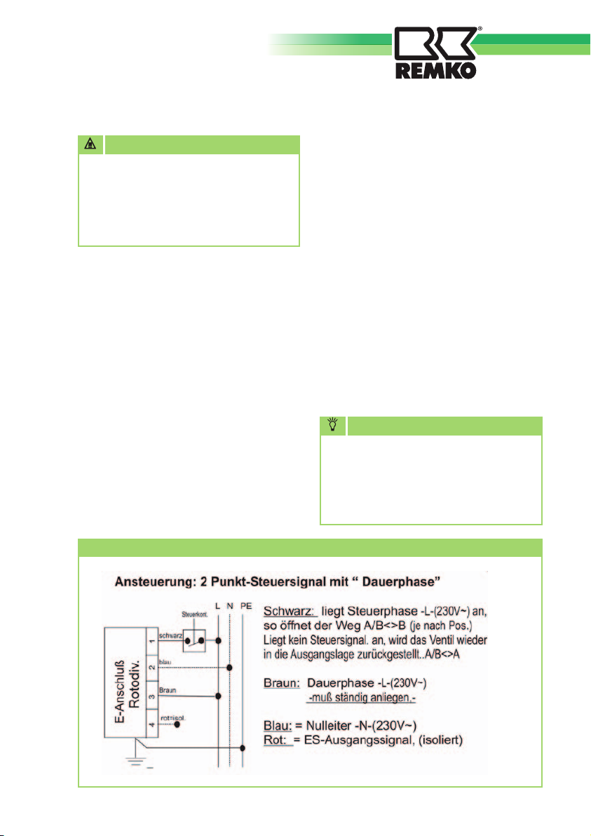
■ The actuator requires a continuous
operating voltage of 230V/1~/50Hz.
This must be connected to the brown
(L) and blue (N) wires. In this state
the valve is in resting position. This
corresponds to heating position and/
or opening of the path AB<->B.
Actuator connection diagram
■ The valve is actuated if the black
wire of the actuator is additionally connected to a voltage of
230V/1~/50Hz. The valve then
turns 90 °C until it reaches the limit
switch. This, in turn, corresponds
to the hot water or cooling position
and/or opening of the path AB<->A.
The valve remains in this state until
the voltage is disconnected from the
black wire again.
■ Every heat pump has appropriately
labelled connection terminals for the
connection of the actuator.
NOTE
Observe the instructions in the
installation manual of the heat
pump for the correct connection.
(Connection diagram and circuit
diagrams, if applicable)
7
Page 8
REMKO 3-WAY SWITCHING VALVE DN32
Manual mode
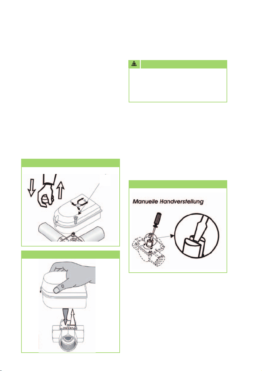
The 3-way switching valve can be
operated manually until the time of
commissioning or in case of a defect of
the actuator. The electrical actuator must
be removed in this case.
To do so, proceed as follows:
1. Loosen fastening screw "2" of the
actuator. This is under the black
cover. Then you can remove the
actuator.
Removal of the actuator
2
ATTENTION
The replacement of the actuator
must take place in a de-energised
(electrical) state. Also disconnect the
main connection to the actuator.
2. The 4-way switching valve can
be moved to the desired position
using a large screwdriver. This
must be able to take place
smoothly and easily. Otherwise the
valve must be replaced, cleaned
and/or repaired.
Manual mode
Removal of the actuator
8
Page 9
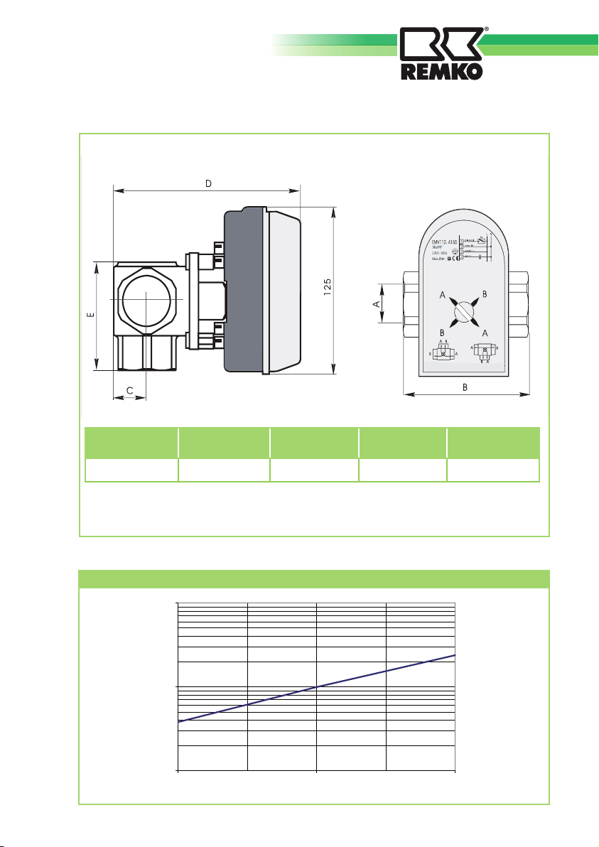
Unit dimensions
1/2 1/4
” ”
1
L-Durchfluß
Measurement AMeasurement BMeasurement CMeasurement DMeasurement
DN 32 90 mm 24 mm 122 mm 69 mm
We reserve the right to modify the dimensions and constructional design as part of the ongoing
technical development process.
Pressure loss diagram
100
10
Durchfluss [m³/h]
1
0,1 1 10
Druckverlust [bar]
E
9
Page 10
REMKO 3-WAY SWITCHING VALVE DN32
Technical data
Unit type 3-way switching valve
Cvs value (pressure loss 1 bar) m3/h 10
Max. operating temperature °C 110
Max. operating pressure bar 6
Max. differential pressure bar 0,4
Switching time s 18
Medium connectors Inches (") 5/4 IG
Lower valve section torque Nm 0,5
Max. actuator torque Nm 8
Electrical connection V 230/1~N
Frequency Hz 50
Power consumption in resting position VA 3
Power consumption during operation VA 7,5
Voltage resistance of the limit switch A/V/Hz 5(1)/250/50
Connection line length mm 2000
Connection line conductor cross-section mm
Permissible environmental tempera-
tures
Protection class according to EN 60355-1
Protection class according to IEC 529 - IP 44
Weight kg 1,37
Nominal width DN 32
EDP No. 260075
2
°C 0-60
- Class II (insulated)
4 x 0.5
We reserve the right to modify the dimensions and constructional design as part of the ongoing technical development process.
10
Page 11
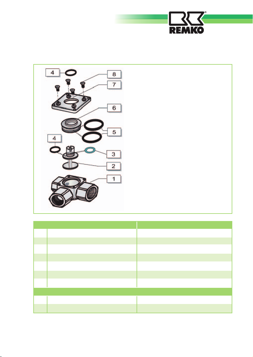
Exploded drawing and spare parts list
No. Designation EDP No.
1 Valve body 1120270
2 Flap with axis 1120271
3 O-ring 8.73x1.78 1120272
4 O-ring 11.91x2.62 1120273
5 O-ring 23.3x2.4 1120274
6 Insert 1120275
7 Valve cover 1120276
Without figure
Actuator 1120277
Indicator plate 1120278
11
Page 12
REMKO INTERNATIONAL
... and also right in your neighbourhood!
Make use of our experience and advice
REMKO GmbH & Co. KG
Air conditioning and heating technology
Im Seelenkamp 12 · D-32791 Lage
Postfach 1827 ·D-32777 Lage
Telephone +49 52 32 6 06-0
Fax +49 5232 606-2 60
E-mail [email protected]
Website www.remko.de
 Loading...