

Page 1
REMKO DZH
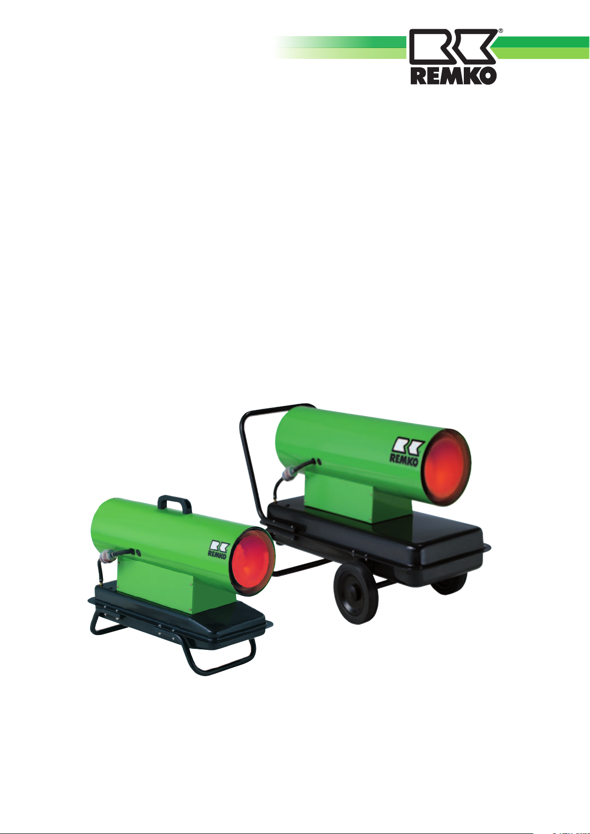
Oil Heaters
Operation· Technology · Spare Parts
Edition GB – W08
Page 2

Page 3
Contents
Safety Notices
Device Description
Mounting Regulations
Commissioning
Shutdown
Maintenance and Care
Trouble Shooting
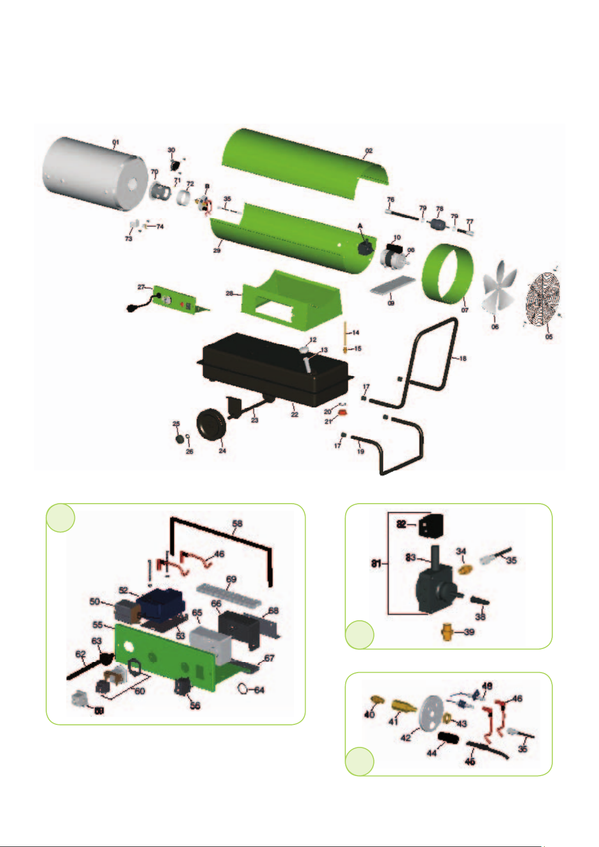
Exploded view DZH 20-2
Spare Parts List DZH 20-2
Exploded view DZH 30-2/50-2
Spare Parts List DZH 30-2/50-2
Exploded view DZH 90
Spare Parts List DZH 90
4
4
5
6
7
8
9
10
11
12
13
14
15
Proper Use
Customer Service and Guarantee
Environmental Protection and Recycling
Electrical Wiring Diagram
Maintenance log
Technical Data
Before commissioning/use of the equipment, these
operating instructions must be read carefully!
16
16
16
17
18
19
Made by REMKO
These instructions are a part of the device and must thus always be
kept in the direct vicinity of the mounting site or on the device itself.
This operating manual is a translation of the German original, Version W-08
Subject to change; errors and typographical errors excepted!
3
Page 4

REMKO DZH
Safety Notices Device Description
When using the appliance, always observe the respective local construction and fire protection ordinances as well as the regulations of the
employers‘ liability insurance associations.
The appliances were subjected to
extensive material, functional, and
quality tests before delivery. Nevertheless, the equipment may present
a danger if it is used by untrained
personnel, improperly, or not according to regulation!
Please observe the following
notices:
■
Before maintenance or servicing
work, the mains plug must be
removed from the socket
■
The unit may be operated only
by personnel who have been
trained in its operation
■
The unit must be set up and
operated in such a way that
people are not endangered by
exhaust fumes and radiated
heat and no fires can break out
■
The unit may be set up and
operated in rooms only if there
is a sufficient amount of air for
the combustion
■
The unit may be operated
without an exhaust duct only in
well-ventilated rooms. People
may not constantly be in the
mounting room
Corresponding prohibition
signs must be posted at the
entryways!
■
The unit may not be operated
without supervision
■
The unit may be set up and
operated only in an environment not at risk of fire or explosion
■
The unit may not be set up in
atmospheres containing oil,
sulphur, or salt
■
A safety zone of 3 m around
the exhaust and 1 m around
the unit and non-flammable
objects must be
observed
■
The protective air suction grille
must always be free of dirt and
loose objects
■
Never insert foreign matters
into the unit
■
The unit may not be exposed to
direct water jets, such as high-
pressure cleaning unit, and so
on
■
All electrical cables of the unit
must be protected from damage (e.g. due to animals)
■
Safety equipment may neither
be bridged nor blocked!
■
Due to the design, a perma-
nent, fixed-location installation
is not intended for this type of
unit
The unit is a mobile heater and is
directly fueled with EL heating oil
or diesel fuel.
The unit works without an exhaust
connection and is solely designed
for commercial use.
The unit is equipped with a fuel
container underneath, fuel filters, maintenance-free axial fans,
high-pressure spraying furnace
with optical flame monitor, room
thermostat socket, and mains cable
with an earthing contact plug.
The unit complies with the basic
safety and health requirements of
the relevant EU stipulations and is
easy to operate.
Among other things, the devices
have the following uses:
■
Spot heating of
outdoor workplaces
■
Spot heating of
workplaces in open, non firehazard production rooms and
halls
■
Temporary heating of rooms
with a sufficient fresh-air supply
■
De-icing of machines, vehicles,
and non-flammable warehouse
goods
■
Temperature control of parts at
risk of frost
CAUTION
!!
■
Mount the unit only on a
level, non-flammable base
4
The units may be set up only
in well-aerated rooms and not
in living areas or lounges.
Page 5
Mounting Regulations
Sequence of functions
After the unit has been switched on
or in case heating is reqired (automatic function with room thermostat), the supply air fan also switched
on.
After the preliminary ventilation of
the burner, the solenoid valve opens
the fuel supply for the oil nozzle.
The fuel, sprayed under high pressure, is enriched with an amount of
oxygen that has been adapted to the
heating capacity and ignited using
an electrical, high-voltage ignition
spark.
As soon as a flame is burning without a problem, the automatic burner relay assume the optical flame
monitoring function.
After a short period of time, hot air
is blown out.
The automatic burner relay perform
all device functions fully automatically and monitor them securely.
In case of any irregularities or an
instable or extinguished flame, the
unit is deactivated by the automatic
burner relay.
The pilot lamp on the automatic
burner relay lights red.
A restart of the unit is only possible
after a manual reset of the automatic burner relay.
After the unit has been shut down
using the operating switch or by
the room thermostat, the supply air
fan continues to run for a certain
period of time to cool the combustion chamber and then shuts down
independently.
Concerning to each room temperature the thermostat operation
repeats the descripted operation
automatically.
When the unit is in use, the safety
guidelines of the employers‘ liability
insurance associations, the respective
country construction ordinances, and
the burning appliance regulations
basically apply.
For example for Germany:
–
Feuerungsanlagenverordnung
(FeuVo) (Furnace Installation Ordinances) of the individual states
–
Unfallverhütungsvorschrift (UVV)
(Accident Prevention Regulation)
„Heiz-, Flämm- und Schmelzgeräte für Bau- und Montagearbeiten“ (Heating, Burning, and
Melting Equipment for Construction and Mounting Work) (VBG
43)
–
Unfallverhütungsvorschrift (UVV)
„Verwendung von Flüssiggas“
(Use of Liquefied Gas) (VBG 21)
–
Arbeitsstättenrichtlinien ASR 5
(Workstation Guidelines)
–
Arbeitsstättenverordnung (Workstation Ordinance) §§ 5 and 14
Outdoor mounting
■
Due to the operation of the unit,
no dangers or unreasonable
nuisances may arise
■
The unit operator must guaran-
tee that unauthorised persons
cannot manipulate the unit or the
energy supply
■
To avoid damage due to incle-
ment weather, the unit must be
mounted in a protected manner
Mounting in closed,
well-ventilated rooms
■
According to the type, the unit
is designed without an exhaust
connection and may be used in
closed rooms only under certain
circumstances
■
To exclude an impermissible pol-
lution of the room air, a reliable
exhaust of the combustion gases
must always be guaranteed
■
The supply of the fresh air
required for proper combustion
must be guaranteed. The fresh
air supply should come through
windows and doors or through
sufficiently sized openings in the
outer wall
■
The unit may be used for room
heating only with a room thermostat (accessory)
The unit may be operated indoors
only if:
-
A sufficient air volume for combustion is supplied to the device.
-
The unit is well aerated and ventilated
-
The amount of pollutants in the
breathing air that is hazardous to
health may not reach an unreasonable concentration
CAUTION
Avoid underpressure or overpressure in mounting rooms
since these states always lead
to combustion-technical
problems.
5
Page 6
REMKO DZH
Commissioning
Before commissioning, the unit
should be checked for noticeable
defects of the operating and safety
appliances, as well as for proper
mounting and correct electrical
connection.
Someone who has been
sufficiently trained in the corresponding handling of the unit must
be assigned with its operation and
monitoring.
CAUTION
In case of defects that endanger the operating safety of the
unit, the operation of the unit
must be shut down immediately and the supervisor must
be informed!
Connecting the devices to the
power supply
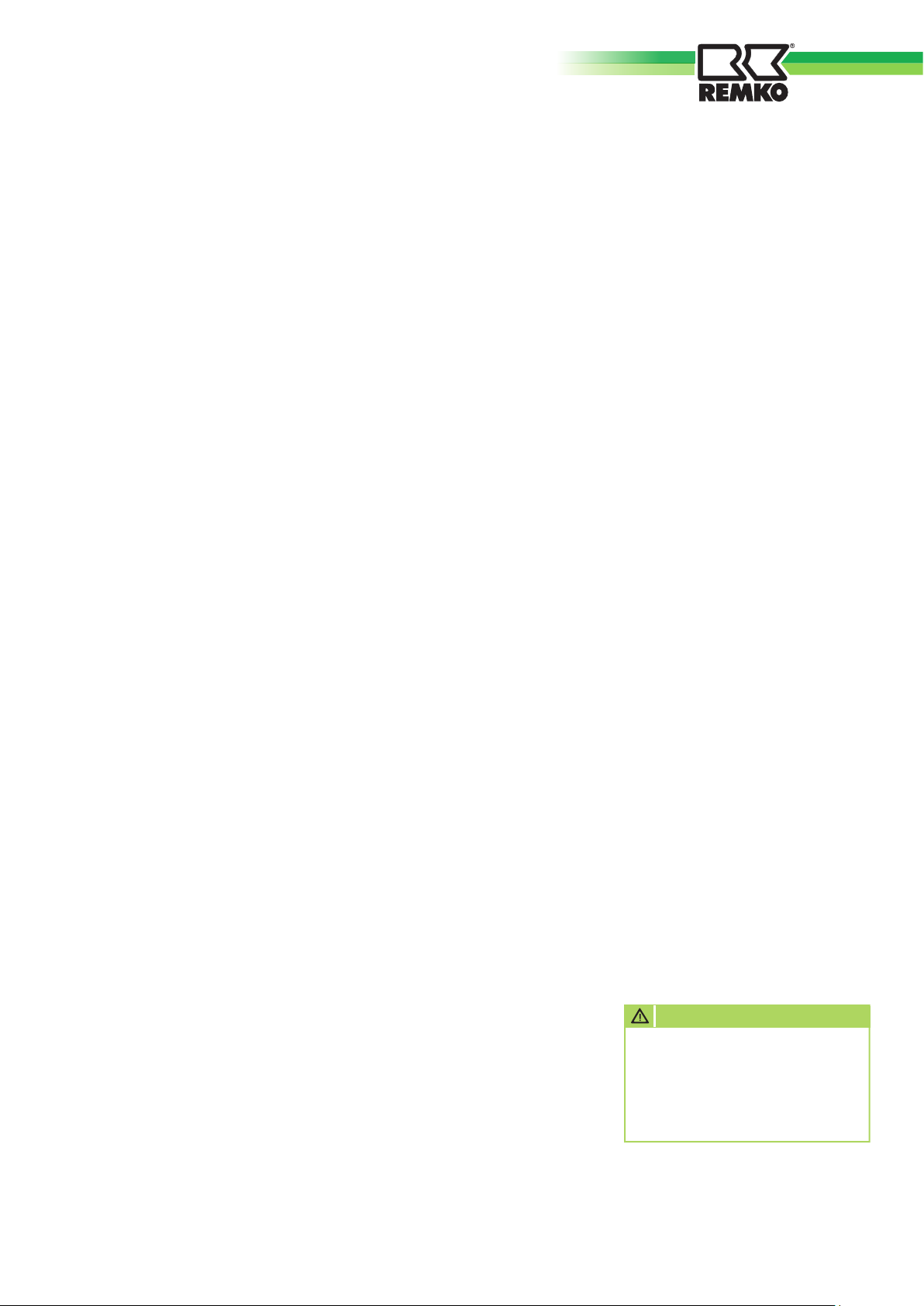
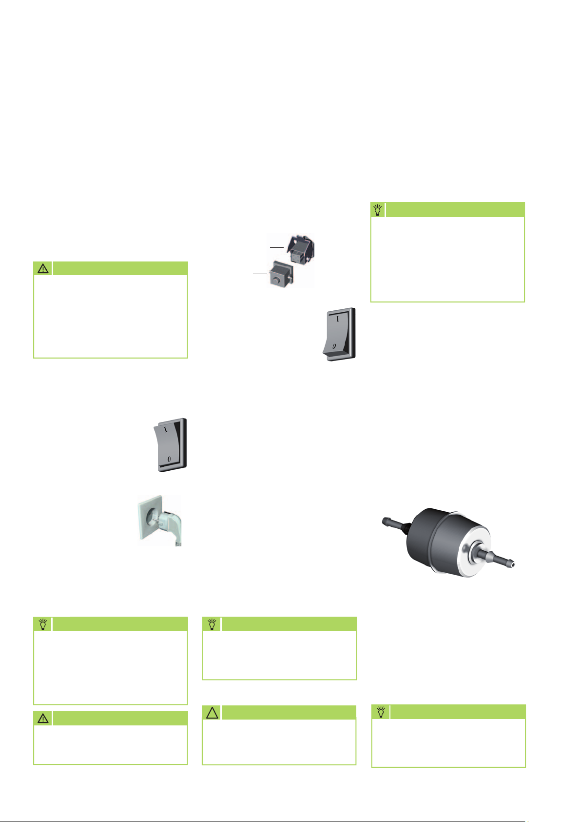
1. Switch the operating
switch to the „0“
position (off).
2. Connect the
mains plug of the
device to a
properly installed
and secured
mains socket. 230 V/50 Hz
NOTE
The electrical connection of
the unit must be performed at
a certain supply point with an
earth-leakage circuit breaker
according to VDE 0100 § 55.
Heating without room thermostat
The unit works in continuous
operation.
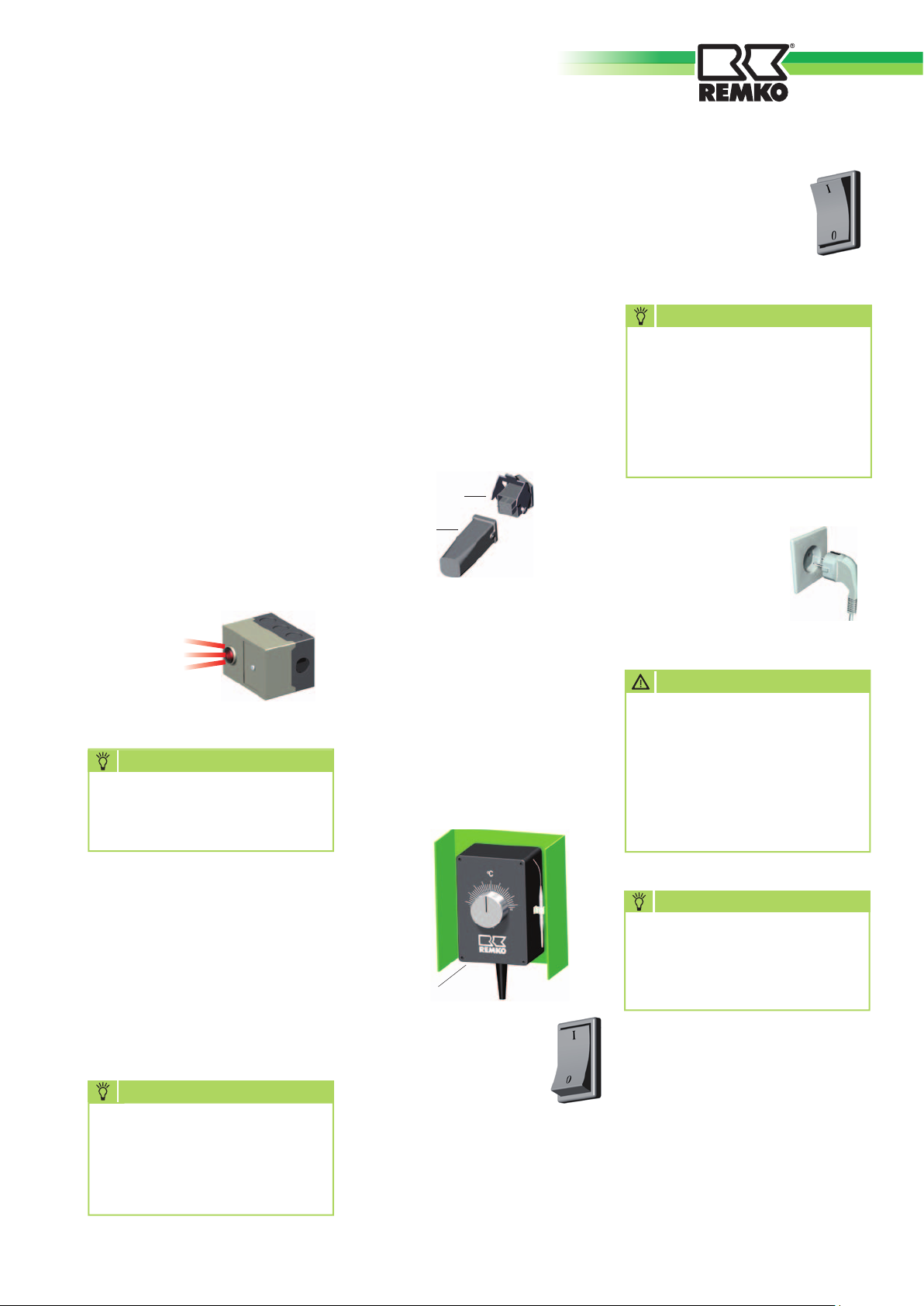
1. Connect the jumper plug 2 included in deliver with the thermostat socket 1 on the device.
1
2
2. Switch the
operating switch to the
„I“ position (on).
Safety distances
■
To guarantee a safe unit
operation, a safety distance of
1 metre around the device must
be observed
■
To blow out the unit, a distance
of at least 3 metres must be
observed
■
The floor and ceiling must be
fire-resistant
■
The intake and exhaust cross-
sections may not be pinched or
blocked by foreign objects
NOTE
In case of overheating of the
devices is a safety shutdown of
the burner relay.
Paraffin formation at low outdoor temperatures
Even in case of low temperatures,
free-flowing heating oil must be
available in sufficient quantities.
NOTE
Paraffin formation can
already take place at temperatures below 5°C.
Corresponding measures and
precautions must be taken to
prevent it.
An optional tank heater is
available as a REMKO accessory.
■
Fill the fuel container with clean
heating oil or diesel fuel
Do not use biodiesel
■
Use only clean, suitable contai-
ners for the filling procedure
Before the start-up of every appliance and every filling of the tank,
the fuel filter must be checked for
soiling or paraffin formation.
The filter is located directly next to
the tank filler neck. The fuel tank
may be filled only when the tank
filter has been inserted into the
filler neck.
CAUTION
All cable extensions may be
used only when unrolled.
6
CAUTION
!
The appliances may not be
placed and runed in fire and
explasition danger vicinities.
NOTE
Only clean fuel through a funnel with a fine filter fill.
Page 7
Shutdown
Notices regarding the safety
cut-off of the unit
The unit fuel supply takes place in
a single line system.
In this regard, the fuel supply to
the nozzle can be interrupted by
blowing air during the initial startup or after the fuel tank has been
completely emptied.
The automatic burner relay of the
appliances shut down due to malfunction in this case.
This shutdown due to malfunction
is indicated by the red pilot lamp
on the control panel.
Reset the automatic burner relay
by pushing this red pilot lamp.
☞
NOTE
The automatic burner relay can
get unlocked after a waiting
periode of 60 sec., only.
Heating with room thermostat (accessory)
The appliances operate fully automatically depending on the room
temperature.
1. Disconnect the
jumper plug 2.
2. Connect the plug 3
of the room thermostat 4 together with the thermostat socket
1 of the device.
1
3
3. Place the room thermostat (4)
at a suitable position in the
room.
The thermostat sensor may not
be in the path of direct hot air
flow and should not be placed
directly on a cold foundation.
4. Adjust the desired temperature
on the room thermostat.
1. Switch the operating
switch to the „0“
position (off).
NOTE
The supply air fan runs to cool
off the combustion chamber
further and switches off later
on its own. The fan may run
several times until it switches
off permanently!
2. In case of longer
downtimes,
disconnect the
unit from the
power mains.
CAUTION
Never interrupt the mains
connection before the entire
cool-down phase comes to
an end.
No warranty claims exist for
damage to the unit due to
overheating!
If the appliance does not start after
several start attempts,
read the „Trouble Shooting“
section
Refill fuel if necessary
NOTE
Never (except in emergency
situations) interrupt the mains
connection before the entire
cool-down phase comes to
an end.
4
5. Switch the
operating switch to the
„I“ position (on).
In case heating is needed, the unit
now switches on automatically and
then off when the desired room
temperature is reached.
NOTE
In case of longer downtimes or
storage of the unit, always fill
the fuel tank with heating oil
or diesel fuel.
7
Page 8
REMKO DZH
Maintenance and Care
The regular care and observance of
some basic prerequisites guarantee
malfunction-free operation and a
long service life of the unit.
After every heating period or independent of the previous operating conditions, the complete unit
including the combustion chamber
and burner must be cleaned of
soot, dust, and dirt.
CAUTION
!
Before all work on the appliance, the mains plug must
be removed from the mains
socket. Especially when the
appliance casing is open, there
is an acute danger of injury
due to the automatically activating fan.
■
For cleaning, use a clean,
slightly moistened cloth with
which you can wipe off the dirt
from the surface .
Do not use a water jet (highpressure cleaner)!
■
Do not use strong cleaning
agents that contain solvent.
Even in case of extreme
soiling, only use suitable
cleaning agent.
■
Clean the tank filter in the filler
neck of the fuel tank regularly.
■
Exchange the fuel filter (ob-
serving the direction of flow)
according to its condition, but
before every heating season
at the latest. The filter is in the
direct vicinity of the tank filler
neck. Note the direction of
flow!
■
Use only clean EL heating oil or
diesel.
Look for paraffin formation!
■
Allow only authorised, expert
personnel to clean the gauze
filter in the fuel pump (only
by DZH 90) and exchange the
nozzle.
■
Regularly check the safety
appliances for correct function.
■
In case of a weakening heating
capacity, formation of smoke,
and/or bad ignition, inspect the
unit and adjust the burner.
■
Observe the regular mainte-
nance and care intervals.
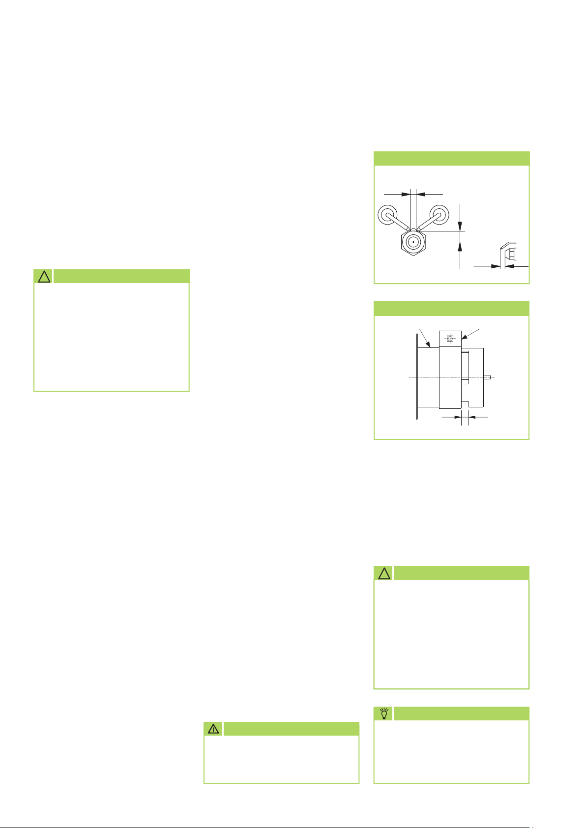
Parameters of initiating electrodes and air slide valve
Adjustment of the initiating electrodes
2 - 3
7
7
All dimensions are values in mm
Adjusting the air slide valve
Burner head Air slide valve
B
Dimension B:
DZH 20-2 = ca. 20 mm
DZH 30-2 = ca. 12 mm
DZH 50-2 = ca. 20 mm
DZH 90 = ca.14 mm
All dimensions are standard values in mm
■
Clean the fuel tank regularly
and then rinse it with clean fuel
or another suitable means.
Do not use water!
■
Always keep the burner head
clean.
■
Check parts subject to wear
such as the oil nozzle, seals,
and so on, and exchange them
if necessary.
We recommend that the oil
nozzle be changed in any case
before the beginning of every
heating season!
8
CAUTION
A safety- technical test
must be carried out after all
work at the appliances.
CAUTION
!
The exhaust values must be
checked and set by authorised,
expert personnel.
The flame must burn out
within the combustion chamber. The flame may not extend
outside of the combustion
chamber.
NOTE
Adjustment and maintenance
tasks may be performed only
by authorised expert
personnel!
Page 9
Trouble Shooting
Faults: Cause:
The supply air fan does not actuate. 2 – 3 – 4 – 6 – 7 – 8 – 25
The fan is running, but the burner does not ignite. 1 – 5 – 6 – 9 – 10 – 11 – 12 – 13 – 14 – 15 – 16 – 17
Das Gerät geht ohne Flammbildung auf Störung. 20 – 21 – 23 – 26
Das Gerät schaltet während des Betriebes aus. 4 – 5 – 6 – 7 – 8 – 9 – 10 – 11 – 13 – 15 – 16 – 17
(The pilot lamp on the automatic burner lights) 19 – 20 – 21 – 22 – 23 – 26
Formation of smoke during the unit is running 7 – 10 – 11 – 13 – 15 – 17 – 19 – 21 – 22
The appliance does not switch off in „0“ position. 18 – 25
CAUTION
Repair work on the electrical installation and on the burner may be carried out only by authorised, expert
personnel for safety-technical reasons.
Cause: Remedy:
1. Air bubbles in the fuel system during initial start up. Reset the fuel system by pushing the red pilot lamp.
Repead it 3 times if necessary.
2. The appliance does not have a voltage supply. Check the voltage supply and electrical connection.
3. No plug in the thermostat socket. Connect the thermostat or shunt plug with the thermostat socket.
4. The thermostat is set too low. Set the thermostat higher than room temperature.
5. The red pilot lamp of the burner relay is shining. Reset the burner relay by pushing the red pilot lamp.
6. Control relay fault. Change the control relay.
7. The motor is overloaded. Let the motor cool down.
(The fan is running irregularly or is blocked.) Check the fuel pump.
Check the electrical and mechanical functions of the motor.
8. The fuel pump is blocked. Check the fuel pump and exchange if necessary.
9. The fuel container is empty. Fill the container with clean fuel.
10. The oil filter is stopped up. Clean or exchange oil firter.
11. The nozzle is stopped up or has the wrong size. Exchange the nozzle (Pay attention to the right type and size).
12. The electrode is incorrectly adjusted, die isolation is defective. Adjust or exchange it.
13. The air inlet plate of the burner head is not correct or dirty. Adjust it with the CO2-Indicator and pump.
(CO2: 11 – 12 %, Bacharach: 0 – 1).
14. The solenoid valve does not open. Check the solenoid valve and exchange it if necessary.
15. The pump pressure is not correctly set. Adjust the pump pressur using a pressure gauge.
16. The pump coupling is defective. Exchange the pump coupling.
17. Leakage in the suction or in the fuel filter. Check and exchange if necessary.
18. The solenoid volve does not close. Temove the fuel line on the main filter. The flame extinguishes.
19. The protection grille of the supply air fan is dirty. Clean the protection grille.
20. The safety limiter (STB) switchs off. Check the air inlet grill and clean if necessary
and unlock the burner relay (only DZH 90 ).
21. Air bubbles in the fuel system. Start the appliance so that the air escapes through the nozzle.
Repead it 3 times if necessary.
22. Ventilation does not suffice. Open the door or windows.
23. The photoelectric cell is dirty or incorrectly adjusted. Clean the photoelectric cell or exchange it if defective.
25. The operation switch is without function. Check the operation switch and exchange it if necessary.
26. Paraffin formation in the fuel. Clean the fuel system; fill the contain with clean fuel.
Have a look at “Maintenance” too.
9
Page 10
REMKO DZH
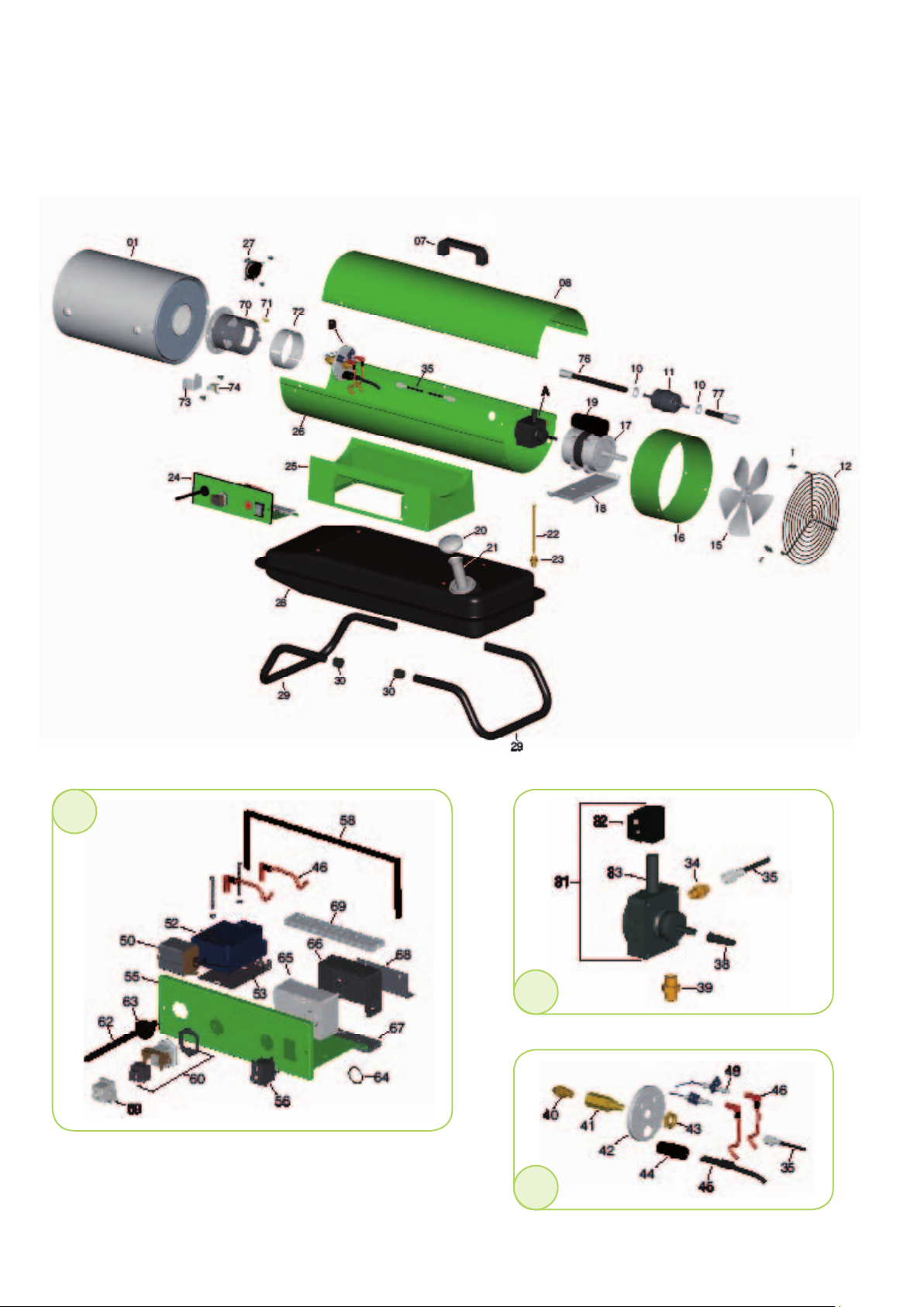
Exploded view DZH 20-2
24
A
B
We reserve the right to make changes in dimensions and design in the interest of technical advances.
10
Page 11
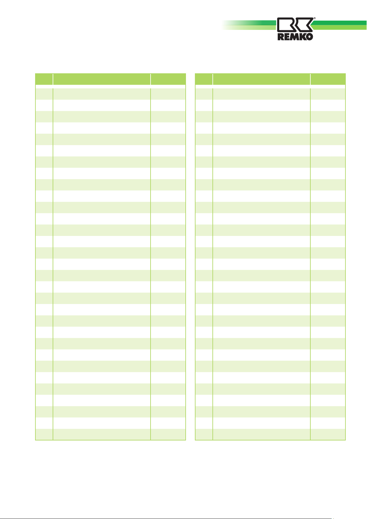
Spare parts list
No. Designation EDP-No.
01 Combustion chamber, complete 1111660
07 Transport grip 1103903
08 Inspection cover 1111661
10 Hose clamp 1103762
11 Fuel filter (disposable) 1102146
12 Intake guard grille 1111662
15 Fan blade 200/31 1111663
16 Fan housing 1111664
17 Fan motor, complete. 75W 1111665
18 Motor carrier 1111666
19 Capacitor 3,15 1107114
20 Tank cap 1102148
21 Tank filter 1103776
22 Intake tube 1111686
23 Connecting nipple ¼“-12x1,75 1111667
No. Designation EDP-No.
42 Mounting plate 1111675
43 Nut 1107134
44 Photoelectric cell mount 1111676
45 Photoelectric cell 1108209
46 Ignition cable with plug 1107137
48 Ignition electrode 1107139
50 Auxiliary Relay 1107375
52 Ignition transformer 1107143
53 Support plate PE 1107188
55 Switch cabinet housing 1107189
56 Operating switch 1111677
58 Seal housing 1107190
59 Jumper plug 1101019
60 Thermostat socket, complete 1101018
62 Mains cable with plug 1107148
24 Electrical module, complete 1107367
25 Support housing 1111668
26 Bottom of housing 1111669
27 Cool-down thermostat 1107182
28 Fuel tank 1111670
29 Stand stirrup 1107121
30 Protective cap 1107122
31 Fuel pump, complete 1107123
32 Magnet coil 1103766
33 Magnet coil core 1111671
34 Connecting nipple prssure line 1111672
35 Oil pressure line 1111673
38 GE coupling, complete 1107129
39 Connecting nipple intake line 1111674
40 Nozzle 1107131
41 Nozzle cradle 1107132
63 Pull relief 1107149
64 Sealing ring OR 22 1111678
65 Automatic burner relay 1102239
66 Relay socket 1102534
67 Plate PG 1102533
68 Relay fitting 1107191
69 Terminal strip 1103781
70 Burner pipe 1111679
71 Protective cap 1111680
72 Air slide 1111681
73 Support plate (STB) 1111682
74 Temperature limiter (STB) 1111683
76 Suction pipe PF 1111684
77 Suction pipe TF 1111685
xx
Undercarriage, optional 1011225
xx
Tank heater, optional 1002518
xx = not shown
When ordering spare parts, always list the device number and the device type (see the type plate) in addition to the EDP number.
11
Page 12
REMKO DZH
Exploded view DZH 30-2/50-2
27
A
B
12
We reserve the right to make changes in dimensions and design in the interest of technical advances.
Page 13
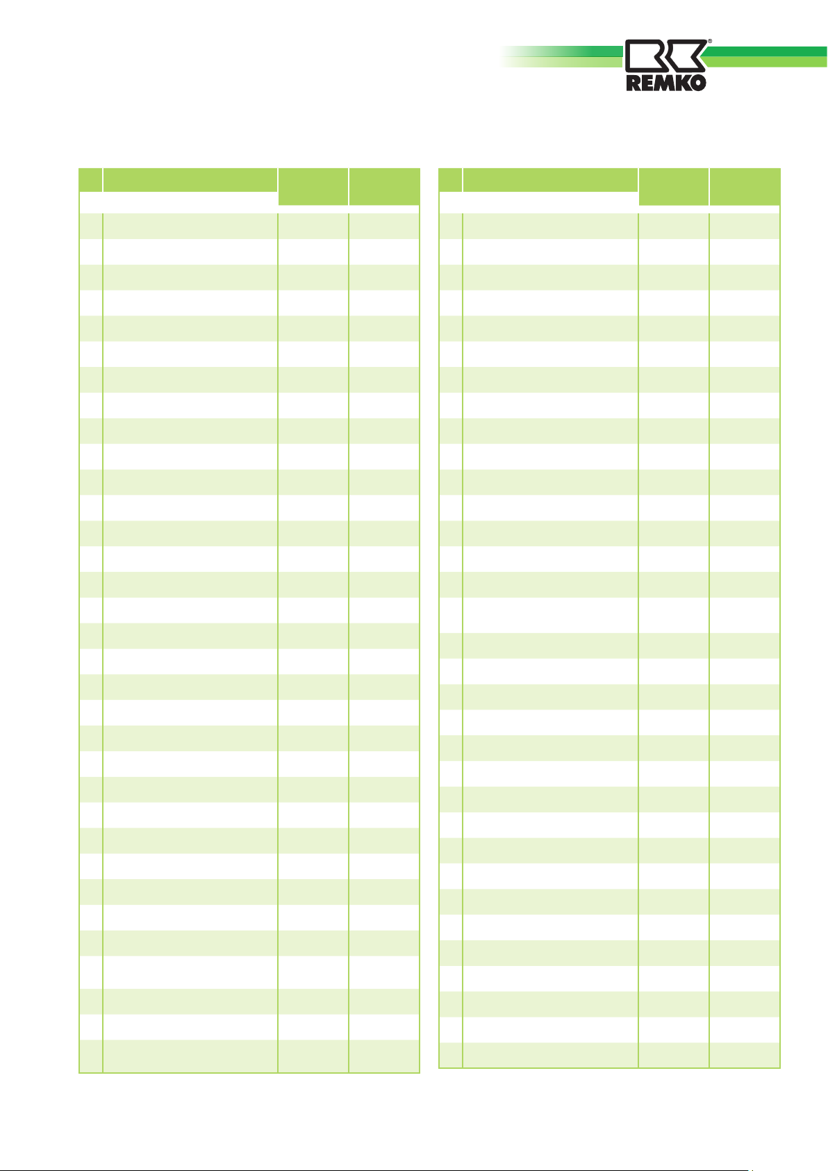
Spare parts list
No.
Designation DZH 30-2 DZH 50-2
EDP-No. EDP-No.
01 Combustion chamber, cpl. 1111690 1111705
02 Inspection cover 1111691 1111706
05 Intake guard grille 1111692 1111707
06 Fan blade 1111693 1111708
07 Fan housing 1111694 1111709
08 Fan motor, complete 1111695 1111710
09 Motor carrier 1111696 1111711
10 Capacitor 1107160 1107174
12 Tank cap 1102148 1102148
13 Tank filter 1103776 1103776
14 Suction tube 1111697 1111712
15 Connecting nipple 1111667 1111667
17 Protective cap 1107122 1107122
18 Transport stirrup 1107163 1111713
No.
Designation DZH 30-2 DZH 50-2
EDP-No. EDP-No.
40 Nozzle 1107126 1111717
41 Nozzle cradle 1107132 1107132
42 Mounting plate 1111675 1111675
43 Nut 1107134 1107134
44 Photoelectric cell mount 1111676 1111676
45 Photoelectric cell 1108209 1108209
46 Ignition cable with plug 1107137 1107137
48 Ignition electrode 1107139 1107139
50 Auxiliary Relay 1107375 1107375
52 Ignition transformer 1107143 1107143
53 Support plate PE 1107188 1107188
55 Switch cabinet housing 1107189 1107189
56 Operating switch 1111677 1111677
58 Seal housing 1107190 1107190
19 Stand stirrup 1107164 1107164
20 Sealing ring/Drain plug 1103777 1103777
21 Drain plug 1103778 1103778
22 Fuel tank 1111699 1111714
23 Axle 1107166 1107166
24 Wheel 1102155 1102155
25 Hub cap 1101623 1101623
26 Circlip 1101622 1101622
27 Electrical module, cpl. 1107367 1107367
28 Support housing 1111700 1111715
29 Bottom of housing 1111701 1111716
30 Cool-down thermostat 1107182 1107182
31 Fuel pump, complete 1107123 1107123
32 Magnet coil 1103766 1103766
33 Magnet coil core 1111671 1111671
Connecting nipple
34
pressure line
1111672 1111672
35 Oil pressure line 1111673 1111673
38 GE coupling, complete 1107129 1107129
Connecting nipple intake
39
line
1111674 1111674
59 Jumper plug 1101019 1101019
Thermostat socket,
60
complete
1101018 1101018
62 Mains cable with plug 1107148 1107148
63 Pull relief 1107149 1107149
64 Sealing ring OR 22 1111678 1111678
65 Automatic burner relay 1102239 1102239
66 Relay socket 1102534 1102534
67 Plate PG 1102533 1102533
68 Relay fitting 1107191 1107191
69 Terminal strip 1103781 1103781
70 Burner pipe 1111702 1111702
71 Protective cap 1111680 1111680
72 Air slide 1111681 1111681
73 Support plate (STB) 1111682 1111682
74 Temperature limiter (STB) 1111683 1111683
76 Suction pipe PF 1111703 1111703
77 Suction pipe TF 1111704 1111704
78 Fuel filter (disposable) 1102146 1102146
79 Hose clamp 1103762 1103762
When ordering spare parts, always list the device number and the device type (see the type plate) in addition to the EDP number.
13
Page 14
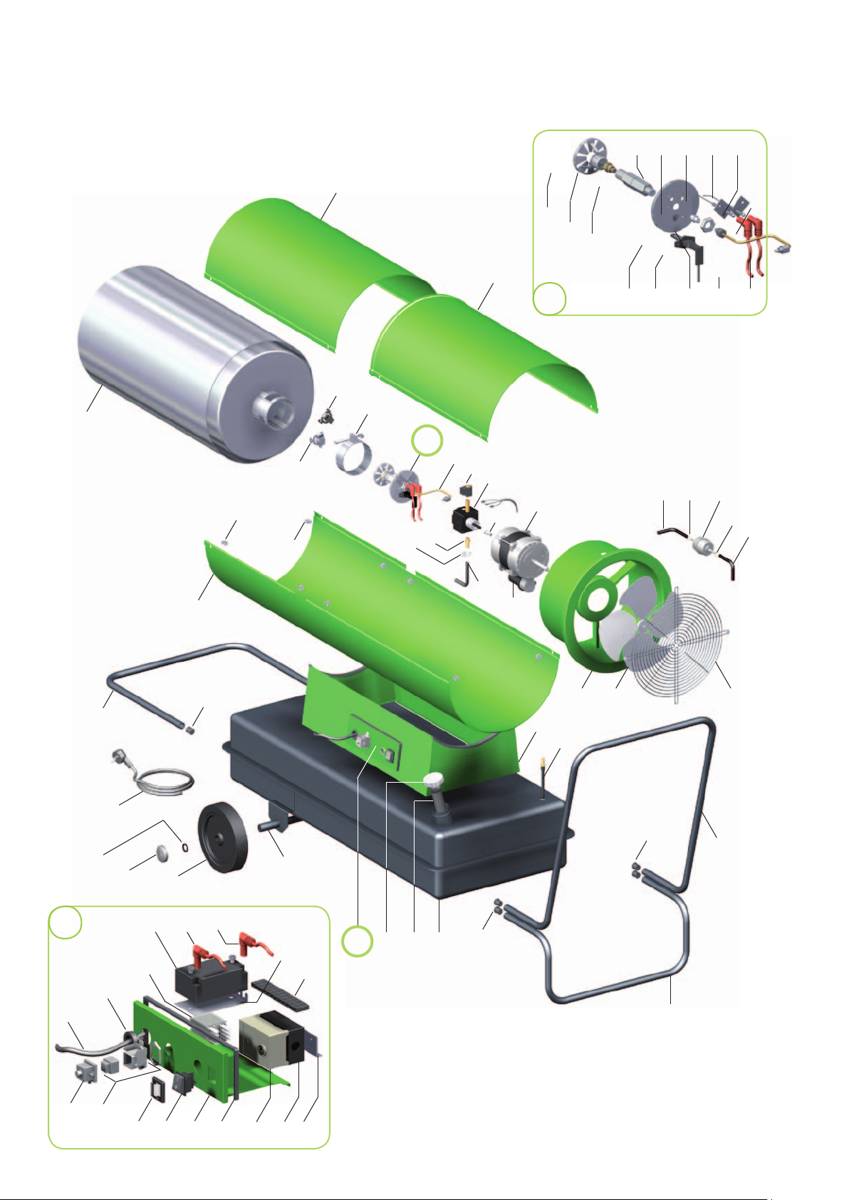
REMKO DZH
Exploded view DZH 90
3
45
45
48
53 54 55 55A56
1
58
50
51
52
2
61 56 546263
4
5
A
58
6
7
16
10
9
8
15 16
17
16
15
35
40
43
39
40
65
38
37
71 56
70
44
29
56
36
72
73
35
15
11
22
21
25
24
29
303132
29
28
20
27
14
75
76
77
78 80
81
82 83 84
We reserve the right to make changes in dimensions
and design in the interest of technical advances.
Page 15
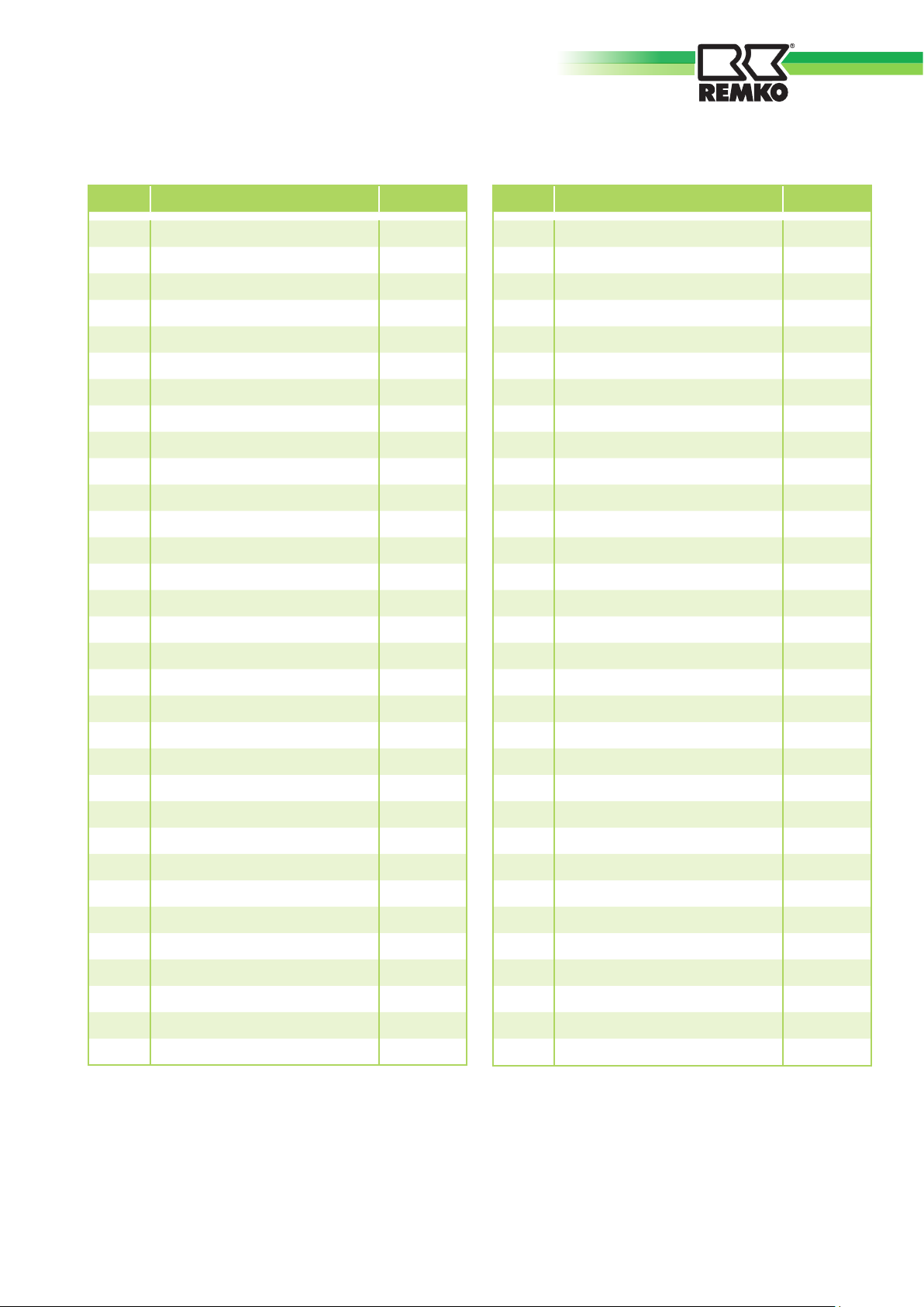
Spare parts list
No.
Designation
EDP no.
1 Cover 1107350
2 Inspection cover 1107351
3 Combustion chamber cpl. 1107352
4 Temperature limiter (STB) 1107353
5 Air inlet plate 1107354
6 Solenoid coil 1103766
7 Fuel pump cpl. 1103765
8 Hose connection 1102109
9 Pump coupling 1107355
10 Fan motor cpl. 1107356
11 Condenser 1107357
15 Fuel hose 1107104
16 Hose clamp 1103762
17 Fuel filter (one-way) 1102146
20 Air inlet grille 1107358
21 Fan blade 1107359
No.
Designation
EDP no.
44 Lower cover 1107370
45 Nut 1107371
48 Re-cooling thermostat 1107182
50 Swivel disc 1103743
51 Nozzle 1107372
52 Nozzle mounting 1103745
53 Assembly plate 1107373
54 GE screw attachement 1103749
55 Ignition electrode 1103747
56 Ignition cable incl. plug 1107137
58 Oil pressure pipe 1107125
61 Screw nut 1107134
62 Photoelectric cell 1108209
63 Photo cell holder 1301560
65 Strain relief 1107149
70 Auxiliary relay 1107375
22 Fan housing 1107360
24 Suction pipe 1107361
25 Mount housing 1107362
27 Transport clamp 1107363
28 Stand clamp 1107364
29 Protection cap 1107365
30 Fuel container 1107366
31 Fuel filter 1103776
32 Tank lock 1102148
35 Electrical set cpl. 1107367
36 Axle 1107368
37 Wheel 1101621
38 Wheel cap 1101623
39 Retaining ring 1101622
40 electrical cable incl. plug 1107148
Impact clamp
43
1107369
71 Ignition transformer 1107143
72 Carrier plate PE 1107188
73 Plug connection 1103781
75 Shunt plug 1101019
76 Thermostat plug socket cpl. 1101018
77 Protection cap 1101189
78 Switch 1102248
80 Control box housing 1107146
81 Seal 1107190
82 Relay 1102239
83 Relay socket 1102534
84 Relay fitting 1107191
xx
xx
xx = not shown
Seal for drain screw 1103777
drain screw
1103778
When ordering spare parts, always list the device number and the device type (see the type plate) in addition to the EDP number.
15
Page 16

REMKO DZH
Proper Use
Due to their conception and equipping, the devices are designed
solely for heating and ventilation
purposes in industrial or commercial use (no private living area
heating).
The unit may be operated only by
accordingly trained personnel.
The manufacturer is not liable for
damage that occurs due to nonobservance of manufacturer instructions or the legal requirements or
due to unauthorised changes to
the device.
Customer Service and
Guarantee
The prerequisite for any warranty
claims is that the customer or its
recipient has returned the completed „Warranty Document“ included in delivery to REMKO GmbH
& Co. KG at the time of the sale
and commissioning of the unit.
The unit wastested several times at
the factory for perfect function.
If any malfunctions should
occur, however, which cannot be
eliminated by trouble shooting
measures performed by the operator, please consult your dealer or
contract partner.
Environmental Protection and Recycling
Disposal of packaging
When disposing of the packaging
material, think of the environment.
Our equipment is carefully packed
for transport and delivered in a
stable cardboard transport package
on a wooden pallet, if necessary.
The packaging materials are
environmentally friendly and can
be reused.
With the reuse of packaging material, you make a valuable contribution to the reduction of waste and
the preservation of raw materials.
You should thus dispose of the
packaging material at the corresponding disposal sites.
NOTE
Another operation other than
that described in these operating instructions is not
permitted.
Nonobservance leads to the
extinguishment of any liability
and warranty claims.
NOTE
Adjustment and maintenance
tasks may be performed only
by authorised expert
personnel.
Disposal of the old device
The equipment manufacturing
process is subject to constant quality control.
Only high-quality materials that
are recyclable to a great extent are
used.
You also contribute to environmental protection by guaranteeing
that your old unit is disposed of an
environmentally friendly manner.
For this reason, bring the old unit
only to an authorised recycling
company or to a corresponding
disposal site.
16
Page 17
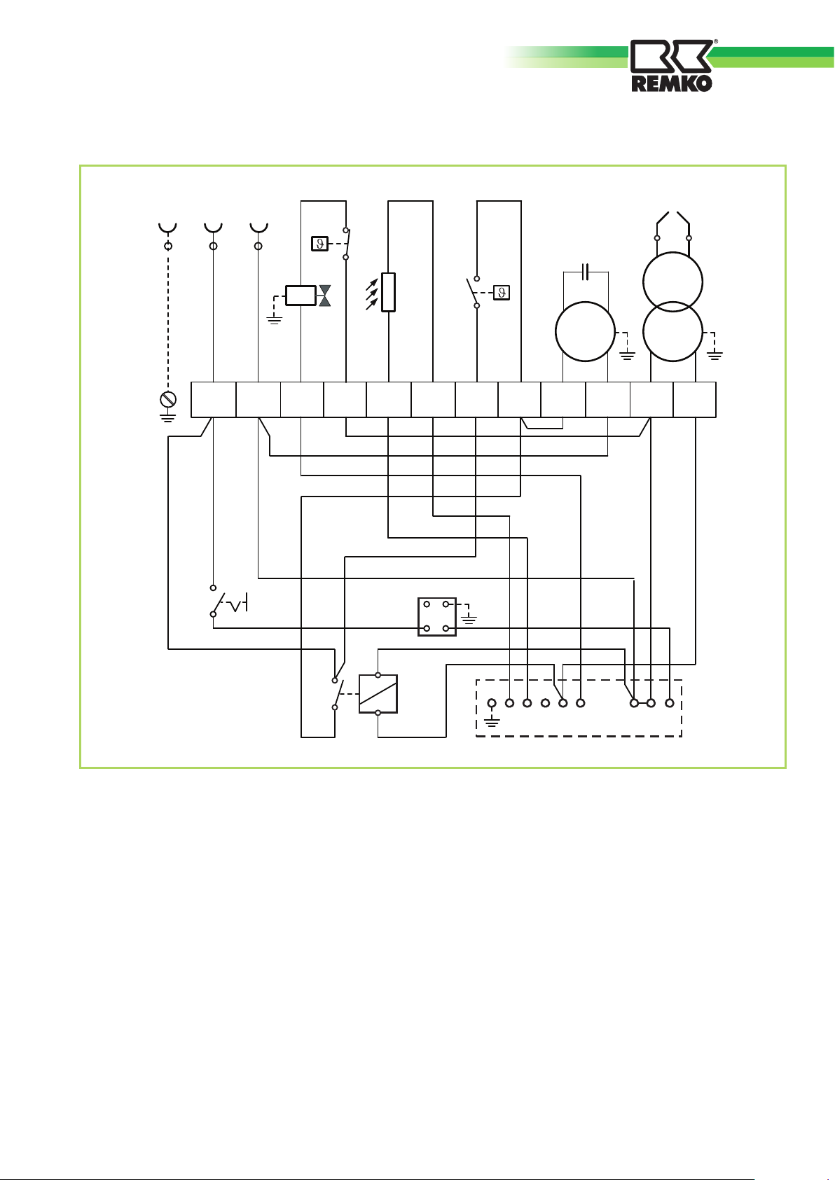
Electrical wiring diagram
230 V / 50 Hz
STB
PE L N
MV
ZE
C
FZ
NK
ZTM
~
1 2
BS
Legend:
3
11
14
4
5 6
2
RT
A1
HS
A2
7
3
8 9 10
1 2 3 4 5 678 N 9
11 12
RS
BS = Operating switch
C = Condenser
FZ = Photoelecrtic cell
HS = Auxiliary relay
M = Motor
MV = Solenoid valve
We reserve the right to make changes in dimensions and design in the interest of technical advances.
NK = Re-cooling thermostat
RS = Relay socket
RT = Thermostat plug socket
STB = Safety limiter
ZE = Ignition electrode
ZT = Ignition transformer
17
Page 18

REMKO DZH
Maintenance log
Model .................................. Model No. ...................................
1 2 3 4 5 6 7 8 9 10 11 12 13 14 15 16 17 18 19 20
Clean unit – surface –
Clean unit – interior –
Clean fan blade
Clean fan housing
Clean condenser
Clean evaporator
Fan function checked
Intake grille with filter cleaned
Check unit for damage
Protective devices checked
All fixing screws checked
Electrical safety test
Test run
✍
Remarks: ..............................................................................................................................................................
.............................................................................................................................................................................
.............................................................................................................................................................................
1. Date ..............
..............................
Signature
6. Date ..............
..............................
Signature
11. Date ............
..............................
Signature
16. Date ............
..............................
Signature
2. Date ..............
..............................
Signature
7. Date ..............
..............................
Signature
12. Date ............
..............................
Signature
17. Date ............
..............................
Signature
3. Date ..............
..............................
Signature
8. Date ..............
..............................
Signature
13. Date ............
..............................
Signature
18. Date ............
..............................
Signature
4. Date ..............
..............................
Signature
9. Date ..............
..............................
Signature
14. Date ............
..............................
Signature
19. Date ............
..............................
Signature
5. Date ..............
..............................
Signature
10. Date ............
..............................
Signature
15. Date ............
..............................
Signature
20. Date ............
..............................
Signature
18
The unit must only be serviced by authorised specialists in compliance with the statutory requirements.
Page 19
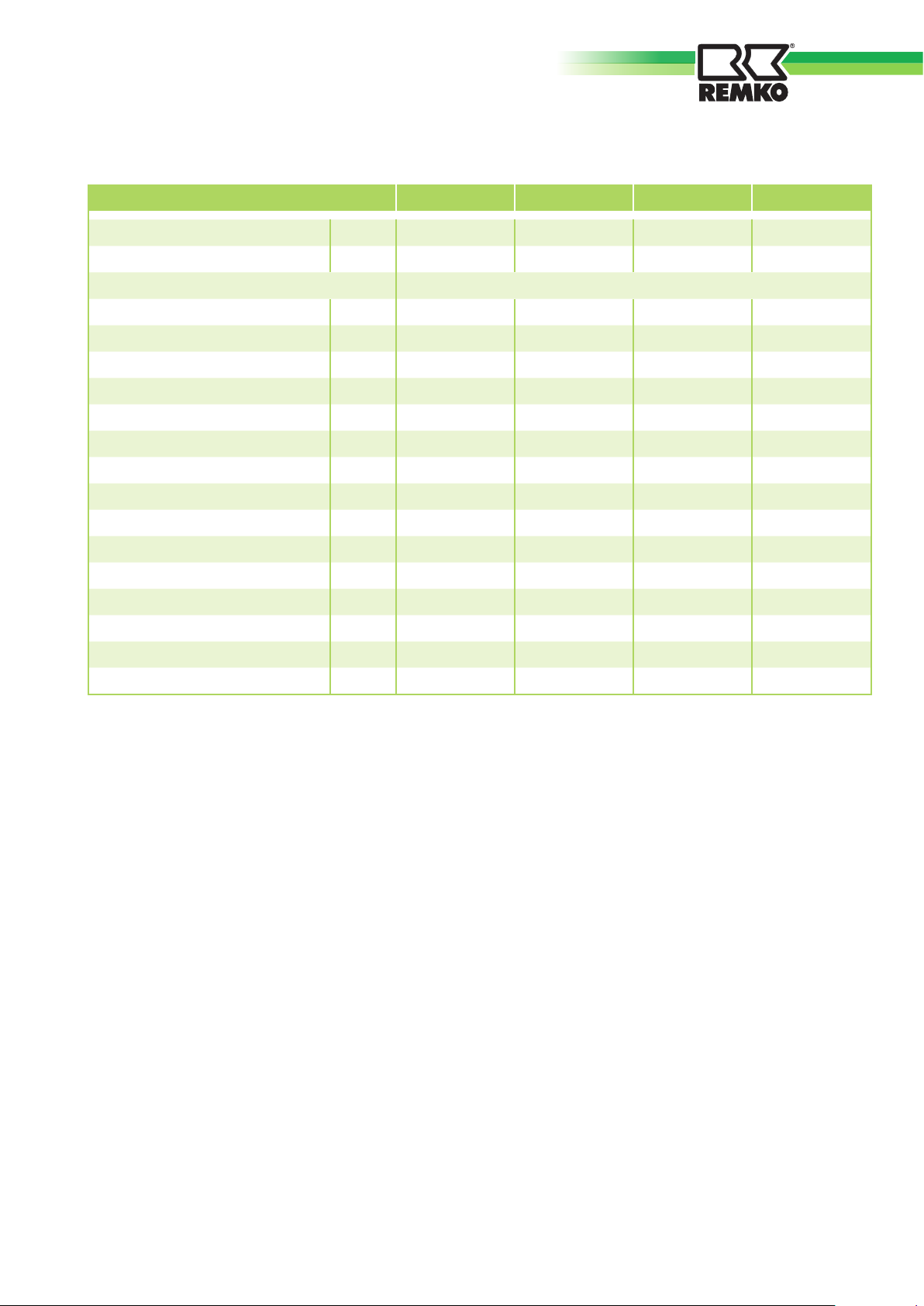
Technical Data
Device type DZH 20-2 DZH 30-2 DZH 50-2 DZH 90
Nominal heating capacity kW 20 36 46 93
Air capacity m3/h 350 605 1400 1800
Fuel EL heating oil according to DIN 51603 or diesel fuel
Max. fuel consumption l/h 2,01 3,62 4,62 9,38
Nozzle (Danfoss)
Pump pressure, approx.
Tank volume Ltr. 17 40 62 105
Voltage supply V/Ph 230/1~ 230/1~ 230/1~ 230/1~
Frequency Hz 50 50 50 50
Max. nominal current A 1,0 1,3 1,8 3,7
Max. power consumption W 200 290 430 690
Fuse protection (on site) A 10 10 10 10
Noise pressure level LpA 1m
Total length mm 800 1050 1090 1400
1)
1)
2)
USG 0,40/80°S 0,60/80°S 0,85/80°S 1,75/80°S
bar 11-12 12-13 14-15 14-14,5
dB(A) 74 77 78 79
Total width mm 300 500 500 655
Total height mm 520 615 740 890
Weight kg 21 37 43 84
EDP no: 116202 116302 116502 116900
1)
The said pump nozzle sizes and pressures resulting from adjust tests to the test stand.
The oil flow was calibrated.
Due to product-specific nozzle / pressure and tolerances as well as the oil temperature, the detail
to be regarded as guidelines only.
2)
Noise measurement according to DIN 45635 - 01 - Cl. 3
We reserve the right to make changes in dimensions and design in the interest of technical advances.
19
Page 20
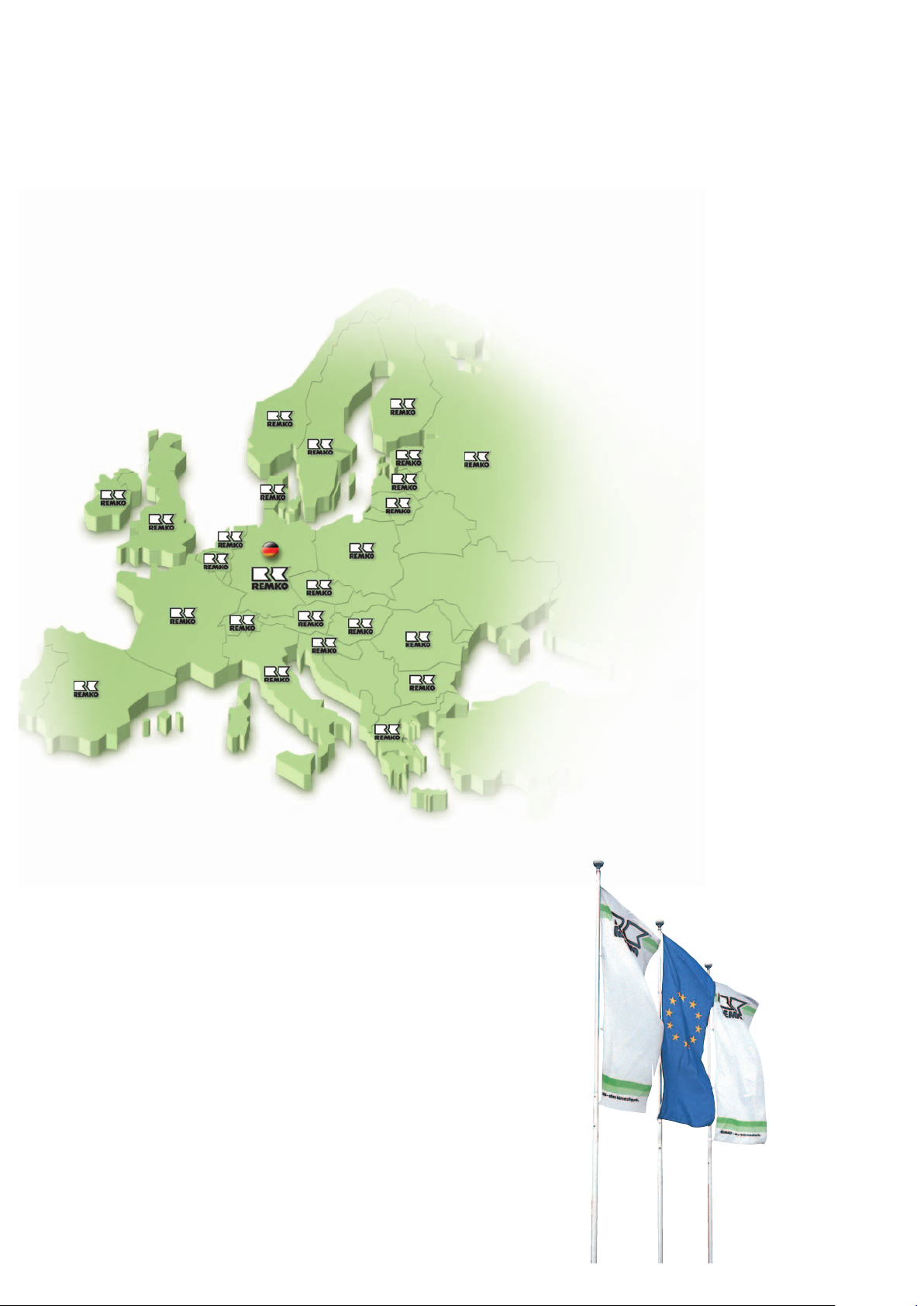
REMKO INTERNATIONAL
… and somewhere near you!
Take advantage of our experience and consulting services
Consulting
Through intensive training, we make
sure the expert knowledge of our
consultants is always up-to-date. This
has given us the reputation of being
more than just a good, reliable supplier:
REMKO, a partner
that helps solve problems.
Sales
REMKO not only provides an extensive
sales network in Germany and abroad,
but also unusually highly qualified sales
experts.
REMKO sales representatives are more
than just salespeople: they must also be
customer consultants in air conditioning
and heating technology.
Customer care
Our devices function precisely and reliably. If a malfunction appears, however,
REMKO Customer Care is on the job.
Our extensive network of experienced
dealers guarantees you constant, shortterm, and reliable service.
REMKO GmbH & Co. KG
Air conditioning and heating technology
Im Seelenkamp 12 D-32791 Lage
Postfach 1827 D-32777 Lage
Telephone +49 52 32 6 06-0
Telefax +49 52 32 6 06-2 60
E-mail [email protected]
Website www.remko.de
Subject to technical changes!
 Loading...