


Assembly and operating instructions
REMKO fresh water station EFS 25
Instructions for user and specialist
0039-2013-04 Edition 1, en_GB
Read the instructions prior to performing any task!

Read these operating instructions carefully before commissioning / using this device!
These instructions are an integral part of the system and must
always be kept near or on the device.
Subject to modifications; No liability accepted for errors or misprints!
Installation and operating instructions (translation of the original)

Table of contents
1 Safety and usage instructions............................................................................................................. 4
1.1 General safety notes....................................................................................................................... 4
1.2 Identification of notes...................................................................................................................... 4
1.3 Personnel qualifications.................................................................................................................. 4
1.4 Dangers of failure to observe the safety notes................................................................................ 4
1.5 Safety-conscious working............................................................................................................... 4
1.6 Safety instructions for the operator................................................................................................. 5
1.7 Safety notes for installation and inspection tasks........................................................................... 5
1.8 Unauthorised modification and changes......................................................................................... 5
1.9 Intended use................................................................................................................................... 6
1.10 Safety-conscious working............................................................................................................. 4
1.11 Warranty........................................................................................................................................ 6
1.12 Transportation and packaging....................................................................................................... 6
1.13 Environmental protection and recycling........................................................................................ 6
2 Technical data....................................................................................................................................... 7
2.1 Unit data.......................................................................................................................................... 7
2.2 Pressure loss characteristic curve.................................................................................................. 8
3 Unit description..................................................................................................................................... 9
4
Design and planning........................................................................................................................... 10
4.1 General Information...................................................................................................................... 10
4.2 Design of the storage tank............................................................................................................ 11
5 Circulation operation.......................................................................................................................... 12
6 Assembly and installation (Specialist).............................................................................................. 12
7 Commissioning (specialist)............................................................................................................... 14
7.1 General Information...................................................................................................................... 14
7.2 Filling the primary circuit............................................................................................................... 14
7.3 Commissioning the controller........................................................................................................ 15
7.4 Maximum dispensing medium flow rate........................................................................................ 16
7.5 Setting the Temperature............................................................................................................... 18
7.6 Commissioning report................................................................................................................... 19
8 Maintenance........................................................................................................................................ 19
9 Depiction of spare parts (specialist)................................................................................................. 20
10 Index..................................................................................................................................................... 22
3

REMKO fresh water station
1
1.1
Carefully read the operating manual before commissioning the units for the first time. It contains
useful tips and notes such as hazard warnings to
prevent personal injury and material damage.
Failure to follow the directions in this manual not
only presents a danger to people, the environment
and the system itself, but will void any claims for
liability.
Keep this operating manual and the refrigerant
data sheet near to the units.
1.2
This section provides an overview of all important
safety aspects for proper protection of people and
safe and fault-free operation.The instructions and
safety notes contained within this manual must be
observed in order to prevent accidents, personal
injury and material damage.
Notes attached directly to the units must be
observed in their entirety and be kept in a fully
legible condition.
Safety notes in this manual are indicated by symbols. Safety notes are introduced with signal words
which help to highlight the magnitude of the danger
in question.
Safety and usage instructions
General safety notes
Identification of notes
DANGER!
CAUTION!
This combination of symbol and signal word
warns of a potentially hazardous situation,
which if not avoided may cause injury or material and environmental damage.
NOTICE!
This combination of symbol and signal word
warns of a potentially hazardous situation,
which if not avoided may cause material and
environmental damage.
This symbol highlights useful tips and recommendations as well as information for efficient
and fault-free operation.
1.3
Personnel qualifications
Personnel responsible for commissioning, operation, maintenance, inspection and installation must
be able to demonstrate that they hold a qualification which proves their ability to undertake the
work.
Contact with live parts poses an immediate
danger of death due to electric shock. Damage
to the insulation or individual components may
pose a danger of death.
DANGER!
This combination of symbol and signal word
warns of a situation in which there is immediate
danger, which if not avoided may be fatal or
cause serious injury.
WARNING!
This combination of symbol and signal word
warns of a potentially hazardous situation,
which if not avoided may be fatal or cause
serious injury.
Dangers of failure to observe
1.4
the safety notes
Failure to observe the safety notes may pose a risk
to people, the environment and the units. Failure to
observe the safety notes may void any claims for
damages.
In particular, failure to observe the safety notes
may pose the following risks:
n The failure of important unit functions.
n The failure of prescribed methods of mainte-
nance and repair.
n Danger to people on account of electrical and
mechanical effects.
1.5
Safety-conscious working
The safety notes contained in this manual, the
existing national regulations concerning accident
prevention as well as any internal company
working, operating and safety regulations must be
observed.
4

Safety instructions for the oper-
1.6
ator
The operational safety of the units and components is only assured providing they are used as
intended and in a fully assembled state.
n The units and components may only be set up,
installed and maintained by qualified personnel.
n The existing regulations concerning accident
prevention must be adhered to.
n Do not operate units or components with
obvious defects or signs of damage.
n Contact with equipment parts or components
can lead to burns or injury.
n Ensure that electrical energy does not pose a
risk.
n Regulations of the VDE and the local energy
supply company must be adhered to.
NOTICE!
Material damage due to mineral oils!
Mineral oil products permanently damage
EPDM seal elements; the sealing properties
may therefore be lost. We do not take responsibility or provide warranty replacements for
damage caused by seals that are damaged in
this way.
– It is essential that you prevent EPDM from
coming into contact with mineral oil substances.
– Use a lubricant that is free of mineral oil
and has a silicone or polyalkylene basis,
such as Unisilkon L250L and Syntheso
Glep 1 made by Klüber, or a silicon spray.
Safety notes for installation and
1.7
inspection tasks
n The operator must ensure that all inspection
and installation work is carried out by authorised and qualified personnel who have thoroughly read the operating manual.
n Works on the pump/system may only be car-
ried out whilst at a standstill as a matter of principle.
n Appropriate hazard prevention measures must
be taken to prevent risks to people when performing installation, repair, maintenance or
cleaning work on the units.
n The setup, connection and operation of the
units and its components must be undertaken
in accordance with the usage and operating
conditions stipulated in this manual and comply
with all applicable regional regulations.
n Regional regulations and laws as well as the
Water Ecology Act must be observed.
n The power supply should be adapted to the
requirements of the units.
n The units and components must be kept at an
adequate distance from flammable, explosive,
combustible, abrasive and dirty areas or
atmospheres.
n Safety devices may not be modified or
bypassed.
NOTICE!
Malfunction!
The fresh water module must be integrated into
the equipotential bonding system of the electrical installation. If this is not ensured by the
pipe network, set up an approved potential
equalisation connection to the main potential
connection.
Unauthorised modification and
1.8
changes
The operational safety of the fresh water module
that was delivered is guaranteed only with
intended use in accordance with section 1.8 of the
operating instructions. Under no circumstances
should the threshold values specified in the datasheet be exceeded.
Modifications or changes to units and components
are not permitted and may cause malfunctions.
Safety devices may not be modified or bypassed.
Original replacement parts and accessories
authorised by the manufacturer ensure safety. The
use of other parts may invalidate liability for
resulting consequences.
5

REMKO fresh water station
1.9
Intended use
The fresh water module is only permitted to be
installed in heating systems between the buffer
tank and the domestic water circuit. Depending on
the design, it may only be installed and operated
vertically!
Use only REMKO accessories in conjunction with
the fresh water module.
Any different or additional use is a non-intended
use. The manufacturer/supplier assumes no liability for damages arising from a non-intended use.
The user bears the sole risk in such cases.
Intended use also includes working in accordance
with the operating and installation instructions and
complying with the maintenance requirements.
The threshold values specified in the technical
data must not be exceeded.
1.10
The safety notes contained in this manual, the
existing national regulations concerning accident
prevention as well as any internal company
working, operating and safety regulations must be
observed.
Safety-conscious working
WARNING!
Plastic films and bags etc. are dangerous
toys for children!
Why:
- Leave packaging material are not around.
- Packaging material may not be accessible to
children!
1.13
Disposing of packaging
All products are packed for transport in environmentally friendly materials. Make a valuable contribution to reducing waste and sustaining raw materials. Only dispose of packaging at approved
collection points.
Environmental protection and recycling
1.11
For warranty claims to be considered, it is essential
that the ordering party or its representative complete and return the "certificate of warranty" to
REMKO GmbH & Co. KG at the time when the
units are purchased and commissioned.
The warranty conditions are detailed in the "General business and delivery conditions". Furthermore, only the parties to a contract can conclude
special agreements beyond these conditions. In
this case, contact your contractual partner in the
first instance.
1.12
Warranty
Transportation and packaging
The units are shipped in sturdy transport packaging or within the heat pump housing. Immediately check the units on delivery and make a note
of any damage or missing parts on the delivery
note. Inform the forwarding agent and contractual
partner. Claims under guarantee made at a later
date will not be accepted.
Disposing of the units and their components
For the manufacture of the units and components,
only recyclable materials have been used. Help
protect the environment by ensuring that the units
or components (for example batteries) are not disposed of in household waste, but only in accordance with local regulations and in an environmentally safe manner, e.g. using authorised disposal
and recycling specialists or council collection
points.
6

2
2.1
Series EFS 25
Operating data
Maximum permitted pressure, primary bar 3
Maximum permitted pressure, secondary bar 10
Operating temperature °C 2-95
Pipe connections
Primary circuit (tank circuit) Inches 3/4" inside thread
Secondary circuit (domestic water circuit) Inches 3/4" outside thread, flat-sealing
Equipment
Gravity brake mmWS 200
Primary pump
Secondary pump
Technical data
Unit data
HE pump with
PWM control, 5-63 watts
(optional) HE pump with
PWM control, 5-63 watts
Heat exchanger 30 Plates
Medium flow rate probe 1 x VFS 2.40
Temperature probe Pt 1000, fast
Materials
Valves Brass
Seals: O-rings EPDM
Flat seals AFM 34, asbestos-free
Plate heat exchanger
Insulation EPP
Gravity brake Hostaform
Stainless steel 1.4400/solder:
99.99% Cu
7

A
B
C
[mWS]
[kPa]
]h/l[
0,0
4,9
9,8
14,7
19,6
24,5
29,4
34,3
39,2
44,1
49,0
53,9
58,8
63,7
68,6
73,5
78,4
0,0
0,5
1,0
1,5
2,0
2,5
3,0
3,5
4,0
4,5
5,0
5,5
6,0
6,5
7,0
7,5
8,0
0 100 200 300 400 500 600 700 800 900 1000 1100 1200 1300
Sekundär
kvs = 2,27
Primär
kvs = 2,65
Grundfos UPM2 15-75 CIL
REMKO fresh water station
Unit data (continued)
Series EFS 25
Dimensions
Height (with insulation) mm 645
Width (with insulation) mm 344
Depth (with insulation) mm 249
Top axis-centre distance mm 86
Bottom axis-centre distance mm 47
Height (with circulation, vertical installation) mm 1115
Height (with circulation, horizontal installation) mm 943
Pressure loss characteristic
2.2
curve
Fig. 1: Pressure loss characteristic curve
A: Pressure [mWS]
B: Medium flow rate [l/h]
C: Pressure [kPa]
8

A
B
C
D
1
2
3
4
7
6
8
9
10
11
5
3
The fresh water station is a pre-installed valve
group that was checked for leak tightness; it is
used to transfer heat between the buffer tank and
the domestic water circuit. It contains a pre-set
controller and important valves for operating the
system:
n Ball valves in the primary circuit
n Piston valves in the secondary circuit
n Safety valve in the secondary circuit
n Pre-installed controller
n Temperature probe on the cold water supply
n Temperature probe on the heating supply
n Ultrasonic flow rate meter on the domestic hot
n Primary pump that can be shut off
n Ball valve for filling/drainage, for bleeding the
Unit description
water outlet
heat exchanger and the pump
NOTICE!
A check for pressure and leak tightness after
successful installation must always be performed before commissioning
Fig. 2: Product description
A: Secondary side: Hot water outlet
B: Primary side: Inlet from the buffer tank
C: Primary side: Return flow to the buffer tank
D: Secondary side: Cold water inlet
1: Piston valve (hot water outlet)
2: Fill/drain valve
3: Safety valve, 10 bar
4: Temperature probe, fast
5: Primary pump
6: Ball valve
7: Ball valve with gravity brake
8: Analogue medium flow rate temperature probe
VFS 2-40
9: Heat exchanger
10: Temperature probe, fast
11: Piston valve (cold water inlet)
9

D
A B C
EFS HGU
RES
M
AB
A
B
A42
REMKO fresh water station
4
4.1
The fresh water station is a fresh water module
that heats domestic water according to the continuous flow heater principle. In order to ensure faultfree operation of the fresh water station, the
system must fulfil certain prerequisites. Before
installation, take some time for planning.
Installation example
The operating mode can be bivalent alternative.
This hydraulic diagram serves merely to assist in planning activities;
the hydraulic system on site must be planned and laid out by the installer!
Subject to technical changes!
Design and planning
General Information
CAUTION!
Danger of scalding due to hot water!
Due to external circulation in the primary circuit, water with a temperature of up to 90 °C
can leak out at the dispensing connection.
– No external pumps are permitted to be
installed between the fresh water module
and the buffer tank.
– The fresh water module is not permitted to
be connected to a heating cycle distributor.
Fig. 3: Fresh water station with optional circulation set and optional return distribution
A: Cold water
B: Hot water
C: Heater heating cycle
D: Circulation
10

4.2
Design of the storage tank
You can use the following table to calculate the approximate required volume of the buffer tank.
Temperature in buffer tank [°C] HW temperature [°C]
50 45 1.5
60
70
80
Sample calculation for the design of the buffer tank:
Temperature of buffer tank: 60 °C, required dispensing medium flow rate at water valve: 20 l/min
DHW temperature set on the controller: 45 °C
How large must the Storage tank be if a 20-minute dispensing operation is to take place without reheating?
20 l/min x 20 min = 400 l
set in controller
45 0.9
50 1.2
55 1.6
45 0.7
50 0.9
55 1.0
45 0.6
50 0.7
55 0.8
Reqd. Storage tank volume per
litre of HW [Litre]
400 l x 0,9 = 360 l ð The heated part of the buffer tank must be 360 litres in size.
The hot water volume depends on the position of the installed S 08 probe (Smart Control hot water
probe). The higher this is installed on the buffer tank, the lower the hot water volume.
11

REMKO fresh water station
5
The fresh water station is (optionally) equipped
with a circulation pump. Three possible operating
modes are stored in the controller to operate the
circulation pump (also see the operating instructions of the controller).
n Pulse-controlled operation (as necessary /
n Time-dependent operation:
n Temperature-dependent operation:
Any of the operating modes can be combined, e.g.
time-dependent and temperature-dependent operation. In this case, circulation is only active if the
temperature falls below the temperature on the circulation temperature probe and the time window is
active. Outside this time window, the circulation
pump can be activated via a dispensing pulse if
pulse-controlled operation is also activated.
Circulation operation
requirement):
Actuating a hot water dispensing connection
for a short time (dispensing impulse: ~2 seconds) starts the circulation pump. The circulation pump then runs for a few minutes (adjustable).
Operation of the circulation pump can be
adjusted on a weekly timer within a freelyselectable period. In this operating mode, circulation begins at the start of the period that is
set. Circulation is deactivated after the set
period expires.
In this operating mode, circulation is only
started if the temperature falls below the minimum temperature that can be set on the circulation temperature probe within the operation
period. Circulation is deactivated after the
adjustable target temperature is reached or
after the set period expires.
NOTICE!
In the delivered state, circulation is not activated (see the operating instructions of the
controller). If the REMKO circulation pump is
installed, the operating mode must be activated
urgently. The speed of the circulation pump
must be specified via the PWM signal. ( Factory setting: 0 % ).
6
If the fresh water station is not installed directly on
the storage tank, note the following points:
1. Determine the installation location of the
2. Transfer the dimensions for the holes to the
3. Drill the holes and insert the enclosed wall
4. Turn the screws into the wall plugs until
5. Remove the front insulation jacket.
Assembly and installation (Specialist)
DANGER!
Danger due to electric shock!
– Remove the power plug before carrying out
electrical work on the controller!
– Plug the power plug of the controller back
in to a socket only after completing all
installation works. In this way, you can prevent the motors from starting up accidentally.
NOTICE!
To avoid damage to the system, the installation
location must be dry, capable of carrying the
load and frost-free.
fresh water module near to the buffer tank.
On the heating side, the pipes must not
exceed a length of 4 m for DN 20.
wall. A corresponding drilling template is provided on the board under the fresh water
module
plugs.
around 40 mm is sticking out of the wall.
12

A
B
Fig. 4: Distance between the holes
6. Hang the fresh water module onto the
screws. Tighten the screws so that the insulation on the sides is flush to the wall.
7. Connect the pipes of the fresh water module
to the system in accordance with Fig. 5.
1. Secondary side:
Hot water outlet,
Connection ¾" AG, flat-sealing
2. Primary side:
Inlet from buffer tank, ¾" IG,
Piping at least DN 20 22 x 1 mm,
recommended DN 25 28 x 1.5 mm
3. Primary side:
Return flow to buffer tank, ¾" IG,
Piping at least DN 20 22 x 1 mm,
recommended DN 25 28 x 1.5 mm
4. Secondary side:
Cold water inlet,
Connection ¾" AG, flat-sealing
Fig. 5: Piping of the fresh water station
A: Pipe distance from the wall
(secondary) = 107 mm
B: Pipe distance from the wall (primary) = 67 mm
13

B
A
C
0°
45°
90°
14
REMKO fresh water station
7
7.1
NOTE:
Open the valves in the pipes and the fresh water
station slowly, in order to prevent pressure
shocks.
Function of the gravity brake
The primary circuit is equipped with a gravity brake
in the ball valve, in order to prevent undesired
gravity circulation.
The gravity brake must be opened to bleed and
clean the system. To do this, turn the ball valve to
the 45° position. The gravity brake is out of operation.
All ball valves and valves must be opened com-
pletely (0°) in order to operate the system.
Commissioning (specialist)
General Information
7.2
Filling the primary circuit
If the storage tank is (partially) filled
CAUTION!
Danger of scalding due to hot water!
The system is under pressure. By opening the
ball valve for filling/drainage, water of up to 90
°C can leak out of the ball valve for filling/
drainage, which may cause bodily injury.
– Open the ball valve for filling/drainage
slowly and from a safe distance.
1. Open the ball valve (F) by turning it to the 0°
position.
2. Fill the storage tank using the filling valves
provided by the customer until you reach an
operating pressure of 1.5 bar*. Use the
heating water in accordance with VDI 2035 /
ÖNorm H5195-1.
3. Connect a hose to the ball valve for filling/
drainage (B). Carefully actuate the ball valve
for filling/drainage (B) and allow the air to
bleed out.
4. Connect the ball valve for filling/drainage (B).
5. Close the ball valve (F) by turning it to the
90° position.
6. Open the ball valve (G) slowly by turning it to
the 45° position.
7. Carefully actuate the ball valve for filling/
drainage (B) and allow the air to bleed out.
8. Connect the ball valve for filling/drainage (B).
9. After bleeding, check the operating pressure
of the storage tank and increase it if necessary.
10. Open the ball valves (F) and (G) completely
by turning them to the 0° position.
Fig. 6: Setting the gravity brake
A: 0° position - Gravity brake in Operation, only
flowing in flow direction.
B: 45° position - Gravity brake out of Operation,
flowing in both directions.
C: 90° position - Ball valve closed, no flow.
1.5 bar in the primary circuit = recommended
minimum value.
The system pressures that depend on the design
and the components of the heating system are
also crucial for the pressure
14

B
AL
F
G
7.3
Commissioning the controller
DANGER!
Danger due to electric shock!
Check whether the probes and pumps to the
controller are connected and whether the controller housing is closed. Only then should you
insert the power plug into the socket.
1. Remove the controller's front panel (see the
controller instructions).
2. In the selection menu of the controller, select
manual operation ("H1"). Switch the PWM
signal of the pump on ("100 %").
3. Allow the pump to run for a few minutes in
order to bleed the FriwaMini.
4. If you continue to hear air noises after this,
connect a hose to the ball valve for filling/
drainage (B). Carefully actuate the ball valve
for filling/drainage (B) while the pump is still
running and allow the air to bleed out.
5. If you no longer hear any air noises, switch
the pump off. To do this, select manual operation ("H1") in the selection menu of the controller.
6. Set the pump to automatic operation ("A").
7. Slowly open the piston valves on the secon-
dary side (A and L).
8. Open a domestic hot water dispensing connection (e.g. water valve) with a flow of at
least 10 l per minute and allow the water to
run for around 2 minutes, in order to bleed
the secondary circuit. Then close all dispensing connections in the secondary circuit.
9. Use the pre-assembled power supply cable
to connect the fresh water station to the
mains (230 V, 50 Hz).
10. Ensure that the fresh water station is correctly included in the equipotential bonding of
the system.
11. Set the required domestic hot water temperature on the controller (see the following
page).
12. The fresh water station is now ready for operation.
Fig. 7: Commissioning the controller
15

B
[kW]
Friwa EFS 25
0
10
20
30
40
50
60
A
[l/min]
0
20
40
60
80
100
120
140
REMKO fresh water station
7.4
Maximum dispensing medium flow rate
The following diagram shows the maximum dispensing medium flow rate depending on the storage tank
temperature; this assumes a pre-set hot water temperature of 45 °C at the dispensing connection. The integrated controller prevents the temperature from decreasing as long as the maximum medium flow rate is not
exceeded.
Fig. 8: Maximum dispensing medium flow rate
A: Dispensing medium flow rate [l/min]
B: Power [kW]
Boundary conditions:
Cold water temperature: 10 °C,
Maximum pressure loss on the domestic water
side of the fresh water station: 1000 mbar
The following examples explain the relationships
between the individual variables of the hot water
temperature, the dispensing medium flow rate and
the buffer tank temperature, and show how these
affect the transmission capacity of the fresh water
station.
The hot water temperature that is set in the
Smart Control controller (S 08 probe) is the reference temperature for the buffer tank. Factory
setting: 45 °C.
Example 1
Hot water temperature at the dispensing connection: 45 °C
Temperature in the buffer tank: 50 °C
ð Maximum dispensing medium flow rate: 18 l/
min, transmission capacity: 44 kW
Example 2
Hot water temperature at the dispensing connection: 45 °C
Maximum dispensing medium flow rate: 25 l/min
ð Temperature in the buffer tank: 60 °C, transmis-
sion capacity: 62 kW
16

The following diagram shows the maximum dispensing medium flow rate if the hot water temperature is 45
A
B
[l/min]
[kW]
Friwa EFS 25
°C at the dispensing connection, after being mixed with cold water with a temperature of 10 °C. The hot
water temperature set on the controller is 60 °C.
Fig. 9: Maximum dispensing medium flow rate
A: Dispensing medium flow rate [l/min]
B: Power [kW]
Boundary conditions:
Cold water temperature: 10 °C,
Example 1
Hot water temperature on the controller: 60 °C
Temperature in the buffer tank: 70 °C
ð Maximum dispensing medium flow rate: 31 l/
min, transmission capacity: 74 kW
Example 2
Hot water temperature on the controller: 60 °C
Maximum dispensing medium flow rate: 25 l/min
ð Temperature in the buffer tank: ~65 °C, trans-
mission capacity: 60 kW
17

REMKO fresh water station
7.5
Setting the Temperature
Set the required (maximum) domestic hot water temperature on the controller under "Para".
To ensure that scalding cannot occur at the water valve, the maximum hot water temperature must not
exceed 60 °C.
Primary side
The temperature required in the buffer tank on the primary side depends on the desired hot water temperature and the required dispensing quantity. The temperature in the buffer tank must be at least 5 K above the
required hot water temperature.
Secondary side
The possible dispensing medium flow rate [l/min] on the water valve depends on the hot water temperature
that is set in the controller and the temperature that is available in the storage tank.
The recommended maximum domestic water medium flow rate through the fresh water module is 25 l/min.
The following table shows the relationship between the storage tank temperature and the maximum dis-
pensing medium flow rate that is connected when the temperature on the valve is 45°C (e.g. single-lever
mixer). If the hot water temperature that is set on the Controller is higher than 45 °C, the dispensing medium
flow rate consists of a mixture of hot and cold water.
The transmission capacity that is specified for this is required to warm the water quantity of the dispensing
medium flow rate [l/min] from 10 °C to 45 °C.
Temperature in
buffer tank probe
S08
[°C]
HW temperature
set on the con-
troller
[°C]
Maximum medium
flow rate from the
fresh water sta-
tion with the set
HW temperature
[l/min]
Maximum dis-
pensing medium
flow rate at the
water valve for an
HW Temperature
of 45 °C
[l/min]
Transmission
capacity of the
fresh water sta-
tion
[kW]
50 45 18 18 44
45 30 30 73
60
70
80
Reheating is not considered if the cold water temperature is 10 °C
50 23 27 64
55 17 22 52
45 38* 38 92
50 33 37 91
55 27 34 84
60 22 31 74
45 38* 38 92
50 38* 43 105
55 35 45 109
60 30 42 102
* maximum medium flow rate: 25 l/min, pressure
loss of the fresh water station is 1000 mbar in this
case (higher values are possible in a limited way
hydraulically).
18

7.6
Commissioning report
System operator
System location
Serial numbers
REMKO EFS25
- Medium flow rate probes
- Controller
- Software version
Primary piping Ø = mm l = m
Secondary piping Ø = mm l = m
Other installations
Are both circuits cleaned and bled properly? (no air noises in the pump)
Are all shut-off valves in the cold water supply opened?
Circulation set
q
Miscellaneous:
q
Return distribution set
q
Bled
q
Opened
q
Is pressure of at least 1.5 bar present on the primary side?
Is pressure of at least 2.5 bar present on the secondary side?
Is an error message shown on the display?
Installation operation
8
After each retroactive structural modification to the
primary side (e.g. installing a dirt separator, a dirt
trap or a mixing valve), you must start a new commissioning procedure in the controller to ensure
optimum regulation.
You should also carry out commissioning again
after adjusting the mixing valve temperature.
A specialist must check that the safety valve is
functioning correctly when commissioning and at
least once per year.
Maintenance
Checked
q
Checked
q
No message
q
Date, Signature
19
2
3
7
1
3
4
7
4
5
6
8
REMKO fresh water station
9
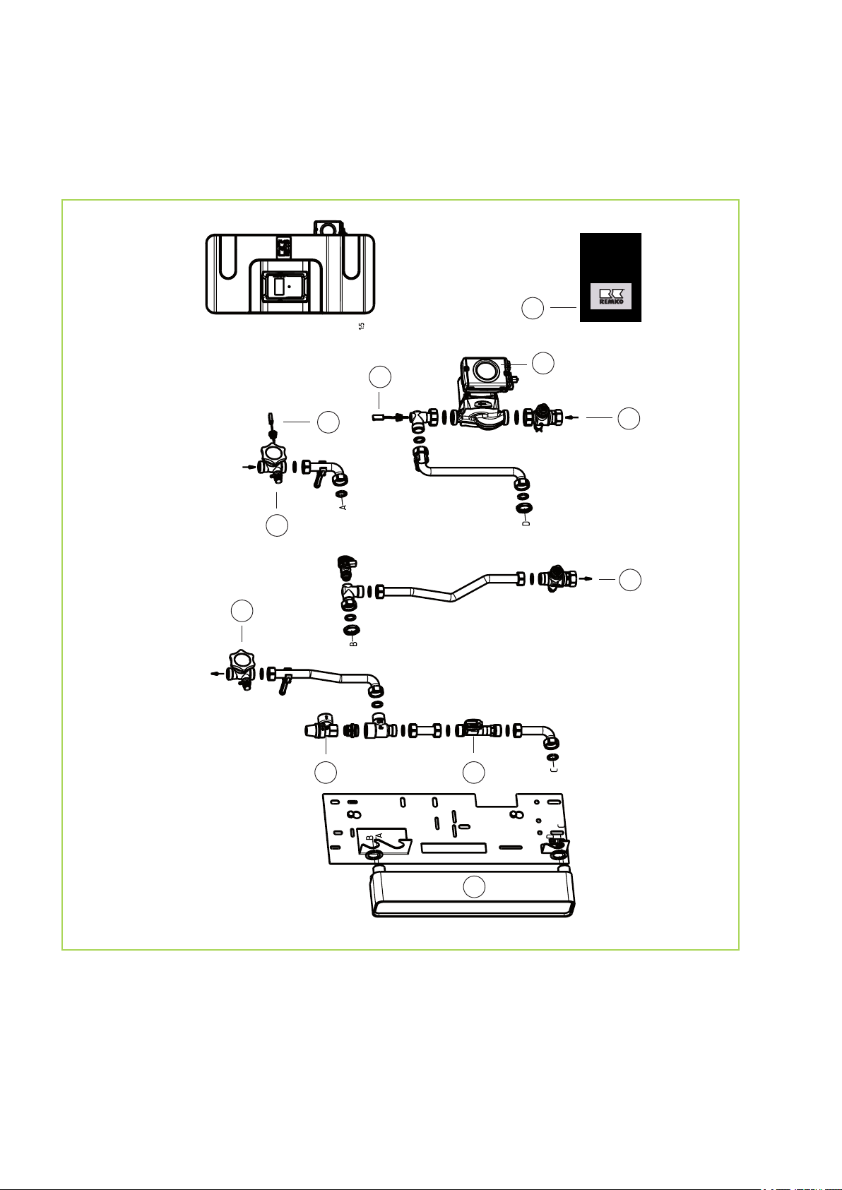
Depiction of spare parts EFS 25
Depiction of spare parts (specialist)
Fig. 10: Spare parts EFS 25
We reserve the right to modify the dimensions and design as part of the ongoing
technical development process
When ordering spare parts, please always state the EDP no., unit number and unit type (see name plate)!
20
Spare parts list EFS 25
2
1
A
No. Description EFS 25
1 Controller 260156-9
2 Grundfoss circulation pump UPM 2-15/75 CIL 2 260155-2
3 Screw-in probe 15 mm G 1/4 260155-3
4 Piston valve DN 15 260155-6
5 Safety valve (1/2" x 3/4") 10 bar 260155-5
6 Medium flow rate probe (analogue) 260155-1
7 Thermo ball valve DN 20 (3/4") 260155-4
8 Plate heat exchanger 260155-8
When ordering spare parts, please always state the EDP number, unit number and unit type
(see name plate)!
Depiction of circulation pump spare parts
Fig. 11: Circulation pump spare parts
Circulation pump spare parts list
No. Description Circulation
pump
A Circulation pump (complete with pipe assembly) 259052
1 Circulation pump 260155-9
2 Piston valve 260155-6
Spare parts not illustrated
Control cable 260155-10
Powerline cable 260155-11
When ordering spare parts, please always state the EDP number, unit number and unit type
(see name plate)!
21

REMKO fresh water station
10
C
Circulation operation.......................................... 12
Commissioning the controller............................. 15
Controller, commissioning ................................. 15
D
Design of the storage tank................................. 11
Dimensions.......................................................... 8
Dispensing medium flow rate, maximum .......... 16
E
Environmental protection..................................... 6
Equipment............................................................ 8
F
Filling the primary circuit.................................... 14
Function of the gravity brake.............................. 14
G
Gravity brake, function ...................................... 14
I
Intended use........................................................ 6
M
Maintenance...................................................... 19
Materials.............................................................. 8
Maximum dispensing medium flow rate............. 16
O
Operating data..................................................... 8
Ordering spare parts.......................................... 21
P
Packaging, disposal............................................. 6
Pipe connections.................................................. 8
Index
Pressure loss characteristic curve....................... 8
R
Recycling............................................................. 6
S
Safety
Dangers of failure to observe the safety
notes............................................................... 4
General........................................................... 4
Identification of notes...................................... 4
Instructions for the operator............................ 5
Note for inspection work................................. 5
Note for installation work
Personnel qualifications.................................. 4
Safety-conscious working........................... 4, 6
Unauthorised modification ............................. 5
Unauthorised replacement part manufacture.. 5
Set the temperature .......................................... 18
Setting the Temperature.................................... 18
Spare parts........................................................ 20
Storage tank, design.......................................... 11
U
Unit disposal........................................................ 6
W
Warranty.............................................................. 6
................................. 5
22


Consulting
Thanks to intensive training,
our consultants are always
completely up-to-date in terms
of technical knowledge. This has
given us the reputation of being
more than just an excellent,
reliable supplier:
REMKO, a partner
helping you find solutions to
your problems.
Distribution
REMKO offers not just a well
established sales network both
nationally and internationally, but
also has exceptionally highlyqualified sales specialists.
REMKO field staff are more than
just sales representatives: above
all, they must act as advisers to
our customers in air conditioning
and heating technology.
SFlbCustomer Service
Our equipment operates
precisely and reliably. However,
in the event of a fault, REMKO
customer service is quickly at
the scene. Our comprehensive
network of experienced dealers
always guarantees quick and
reliable service.
REMKO INTERNATIONAL
… and also right in your neighbourhood!
Make use of our experience and advice
We reserve the right to make technical changes, and provide no guarantee as to the accuracy of this data!
REMKO GmbH & Co. KG
Air conditioning and heating technology
Im Seelenkamp 12 D-32791 Lage
Postfach 1827 D-32777 Lage
Telephone +49 5232 606-0
Telefax +49 52 32 606-2 60
E-mail info@remko.de
Website www.remko.de
 Loading...