


Operating and
installation instructions
REMKO remote controls
Easy-Control remote control for heat pumps
EC 1
0242-2019-11 Edition 1, en_GB
Read the instructions prior to performing any task!

Read these operating instructions carefully before commissioning / using this device!
These instructions are an integral part of the system and must
always be kept near or on the device.
Subject to modifications; No liability accepted for errors or misprints!
Translation of the original

Table of contents
1 Safety and usage instructions............................................................................................................. 4
1.1 General safety notes....................................................................................................................... 4
1.2 Identification of notes...................................................................................................................... 4
1.3 Personnel qualifications.................................................................................................................. 4
1.4 Dangers of failure to observe the safety notes................................................................................ 4
1.5 Safety-conscious working............................................................................................................... 4
1.6 Safety notes for the operator........................................................................................................... 5
1.7 Safety notes for installation, maintenance and inspection.............................................................. 5
1.8 Unauthorised modification and changes......................................................................................... 5
1.9 Intended use................................................................................................................................... 5
1.10 Warranty........................................................................................................................................ 5
1.11 Transport and packaging............................................................................................................... 6
1.12 Environmental protection and recycling........................................................................................ 6
2 Technical data........................................................................................................................................ 7
2.1 Unit data.......................................................................................................................................... 7
2.2 Unit dimensions............................................................................................................................... 7
3 Unit description..................................................................................................................................... 8
4
Scope of delivery.................................................................................................................................. 8
5 Operation............................................................................................................................................... 9
6 Electrical wiring................................................................................................................................... 15
7 Installation........................................................................................................................................... 17
8 Addressing the EC1............................................................................................................................ 18
9 Index..................................................................................................................................................... 19
3
REMKO remote controls
1 Safety and
usage instructions
1.1 General safety notes
Carefully read the operating manual before commissioning the units for the first time. It contains
useful tips and notes such as hazard warnings to
prevent personal injury and material damage.
Failure to follow the directions in this manual not
only presents a danger to people, the environment
and the system itself, but will void any claims for
.
liability
Keep this operating manual and the refrigerant
data sheet near to the units.
1.2 Identification of notes
This section provides an overview of all important
safety aspects for proper protection of people and
safe and fault-free operation.The instructions and
safety notes contained within this manual must be
observed in order to prevent accidents, personal
injury and material damage.
Notes attached directly to the units must be
observed in their entirety and be kept in a fully
legible condition.
Safety notes in this manual are indicated by symbols. Safety notes are introduced with signal words
which help to highlight the magnitude of the danger
in question.
DANGER!
Contact with live parts poses an immediate
danger of death due to electric shock. Damage
to the insulation or individual components may
pose a danger of death.
DANGER!
This combination of symbol and signal word
warns of a situation in which there is immediate
danger
cause serious injury.
, which if not avoided may be fatal or
This combination of symbol and signal word
warns of a potentially hazardous situation,
which if not avoided may cause injury or material and environmental damage.
This combination of symbol and signal word
warns of a potentially hazardous situation,
which if not avoided may cause material and
environmental damage.
This symbol highlights useful tips and recommendations as well as information for efficient
and fault-free operation.
1.3 Personnel qualifications
Personnel responsible for commissioning, operation, maintenance, inspection and installation must
be able to demonstrate that they hold a qualification which proves their ability to undertake the
work.
1.4
Failure to observe the safety notes may pose a risk
to people, the environment and the units. Failure to
observe the safety notes may void any claims for
damages.
In particular, failure to observe the safety notes
may pose the following risks:
n The failure of important unit functions.
n The failure of prescribed methods of mainte-
n Danger to people on account of electrical and
CAUTION!
NOTICE!
Dangers of failure to observe the safety notes
nance and repair
mechanical effects.
.
WARNING!
This combination of symbol and signal word
warns of a potentially hazardous situation,
which if not avoided may be fatal or cause
serious injury
.
1.5 Safety-conscious working
The safety notes contained in this manual, the
existing national regulations concerning accident
prevention as well as any internal company
working, operating and safety regulations must be
observed.
4

1.6 Safety notes for the operator
The operational safety of the units and components is only assured providing they are used as
intended and in a fully assembled state.
n The units and components may only be set up,
installed and maintained by qualified personnel.
n Protective covers (grille) over moving parts
must not be removed from units that are in
operation.
n Do not operate units or components with
obvious defects or signs of damage.
n Contact with certain unit parts or components
may lead to burns or injury
n The units and components must not be
exposed to any mechanical load, extreme
levels of humidity or extreme temperature.
n Spaces in which refrigerant can leak sufficient
to load and vent. Otherwise there is danger of
suffocation.
n All housing parts and device openings, e.g. air
inlets and outlets, must be free from foreign
objects, fluids or gases.
n The units must be inspected by a service tech-
nician at least once annually. Visual inspections and cleaning may be performed by the
operator when the units are disconnected from
the mains.
.
1.7 Safety notes for installation, maintenance and inspection
n The units and components must be kept at an
adequate distance from flammable, explosive,
combustible, abrasive and dirty areas or
atmospheres.
n Safety devices must not be altered or
bypassed.
Unauthorised modification
1.8
and changes
Modifications or changes to units and components
are not permitted and may cause malfunctions.
Safety devices may not be modified or bypassed.
Original replacement parts and accessories
authorised by the manufactured ensure safety
use of other parts may invalidate liability for
resulting consequences.
. The
1.9 Intended use
The units are designed depending on the model
and equipment exclusively as a control unit for the
heat pump and the heating system.
Any different or additional use shall be classed as
non-intended use. The manufacturer/supplier
assumes no liability for damages arising from such
use. The user bears the sole risk in such cases.
Intended use also includes working in accordance
with the operating and installation instructions and
complying with the maintenance requirements.
Under no circumstances should the threshold
values specified in the technical data be exceeded.
n Appropriate hazard prevention measures must
be taken to prevent risks to people when performing installation, repair
cleaning work on the units.
n The setup, connection and operation of the
units and its components must be undertaken
in accordance with the usage and operating
conditions stipulated in this manual and comply
with all applicable regional regulations.
n Local regulations and laws such as Water
Ecology Act must be observed.
n The power supply should be adapted to the
requirements of the units.
n Units may only be mounted at the points pro-
vided for this purpose at the factory. The units
may only be secured or mounted on stable
structures, walls or floors.
n Mobile units must be set up securely on suit-
able surfaces and in an upright position. Stationary units must be permanently installed for
operation.
n The units and components should not be oper-
ated in areas where there is a heightened risk
of damage. Observe the minimum clearances.
, maintenance or
1.10 Warranty
For warranty claims to be considered, it is essential
that the ordering party or its representative complete and return the "certificate of warranty" to
REMKO GmbH & Co. KG at the time when the
units are purchased and commissioned.
The warranty conditions are detailed in the "General business and delivery conditions". Furthermore, only the parties to a contract can conclude
special agreements beyond these conditions. In
this case, contact your contractual partner in the
first instance.
5

REMKO remote controls
1.11 Transport and packaging
The devices are supplied in a sturdy shipping container or inside the heat pump casing. Please
check the equipment immediately upon delivery
and note any damage or missing parts on the
delivery and inform the shipper and your contractual partner
anteed.
Plastic films and bags etc. are dangerous
toys for children!
Why:
- Leave packaging material are not around.
- Packaging material may not be accessible to
children!
. For later complaints can not be guar-
WARNING!
1.12 Environmental protection and recycling
Disposal of packaging
All products are packed for transport in environmentally friendly materials. Make a valuable contribution to reducing waste and sustaining raw materials. Only dispose of packaging at approved
collection points.
Disposal of equipment and components
Only recyclable materials are used in the manufacture of the devices and components. Help protect
the environment by ensuring that the devices or
components (for example batteries) are not disposed in household waste, but only in accordance
with local regulations and in an environmentally
safe manner
cling specialists or at collection points.
, e.g. using certified firms and recy-
6

2 Technical data
60 (±2)
86
86
50
14
14
24
50
90
50
90
A
B
C
2.1 Unit data
Series Easy-Control EC1
Power supply V/Hz 230 AC, 50
Current load (heating cycle pump) A 3
Probe NTC3950, l0K
Accuracy °C/F ± 0.5/± 1
Set the temperature °C 5-35
Temperature display °C 5-99
Ambient temperature °C 0-45
Humidity (non-condensing) % rel. hum. 5-95
Storage temperature °C 5-45
Current consumption W < 1.5
Timing error % < 1
Housing PC +ABS (fire-resistant)
Suitable flush-mounted socket mm
Wire clips
mm
2
86 x 86 square or European 60 mm
round box
Wire 2 x 1.5 or 1 x 2.5
Enclosure class IP30
Keys Capacitive touch keys
We reserve the right to make technical changes for the purpose of technical advancement.
Unit dimensions
2.2
Fig. 1: Dimensions (all measurements in mm)
A: Front view
B: Side view
7
C: Rear view

REMKO remote controls
3 Unit description
The Easy-Control remote control EC 1 is a touch
display with an integrated room probe. Operation is
intuitive and self-explanatory due to its clear
arrangement. For example, to enter the desired
room temperature it is only necessary to touch the
“up/down” arrow keys. The anti-freeze protection
function or an absence program can also be set.
Using the room probe it is possible to realise room
temperature-guided regulation in the heating and
cooling mode. The installation is suitable for a
standard flush-mounted socket. Communication
with the heat pump takes place via a Modbus protocol.
The controller can be used as a wall-mounted
single-room controller
.
4 Scope of delivery
Description Quantity
Easy-Control EC 1 1
Fastening screws 4
Operating manual 1
Fig. 2: Controller as wall-mounted single-room controller
8
6
1
2
4
5
8
7
3
9
1
2
3
4
5
6
7
8
9
10
11
12
13
14
10
11
12
13
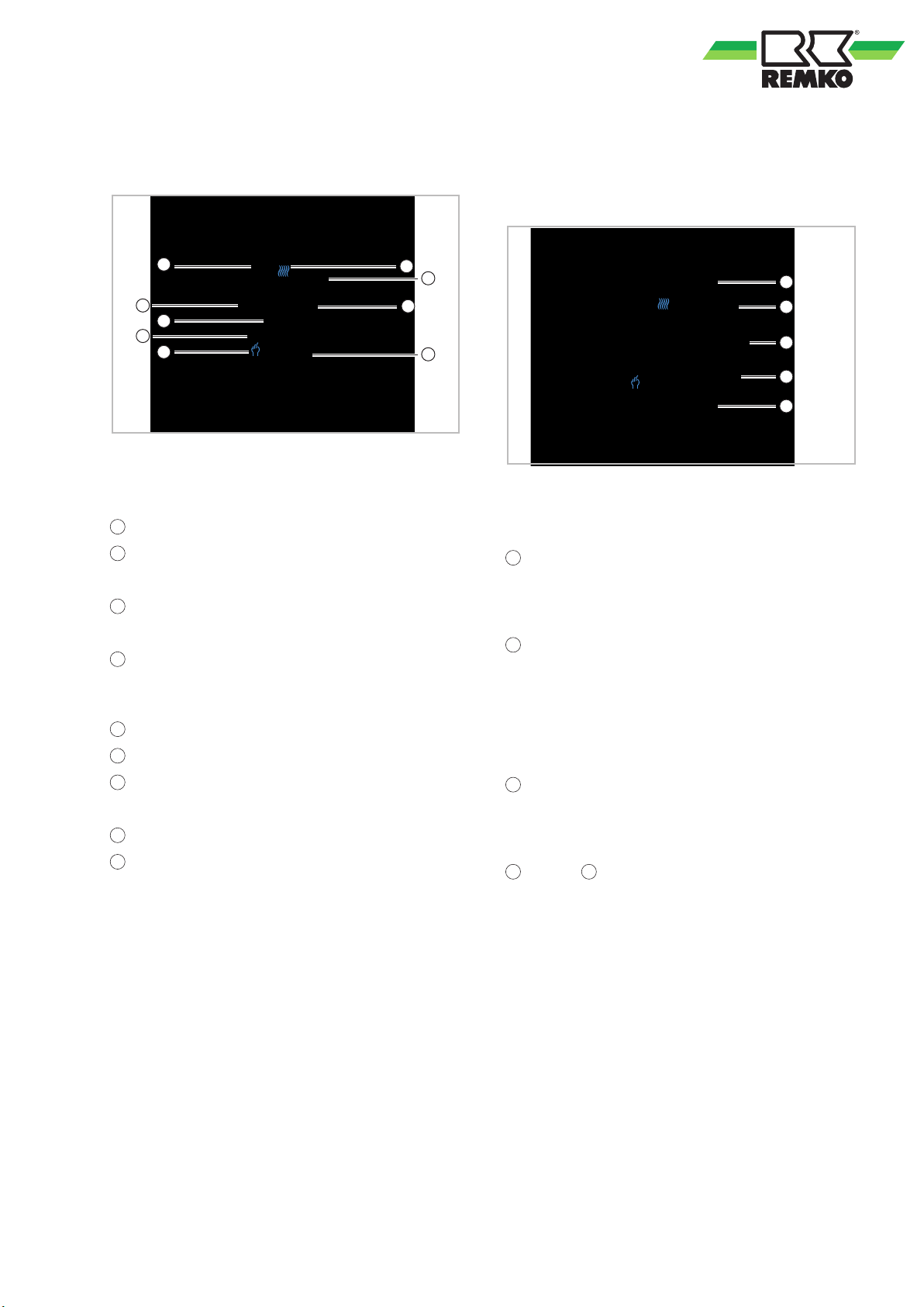
5 Operation
Remote control display
Keys for the remote control settings
Fig. 3: Remote control display
The remote control display is realised through the
corresponding symbols on the touch display
.
Days of the week
Setpoint
Is displayed if the room temperature is set.
Room temperature
Is displayed if the room temperature is displayed.
Automatic mode, time program active
In this case, no time programs of the Smart-Control
T
ouch are active.
Manual mode, no time program
Heating/cooling
Present or absent
It is possible to enter up to 6 heating times per day
.
Room set/actual temperature
ime
T
Fig. 4: Keys on the remote control
The remote control is operated using the relevant
keys on the touch display
.
“On / off” key
Activation of the room temperature regulation. If
the display is switched of
f, anti-freeze protection
mode is active
“M” key
Switching from manual mode to present/absent
mode (time program). The following symbols
appear:
- “Manual” = manual mode
- “Clock” = time program
“Clock” key
Using this key it is possible to select and set the
hours, minutes and days of the week (1-7). To confirm and continue, press the “clock” key.
and the 14 "arrow” keys
T
o set the room temperature touch the “Up/down”
arrow keys [13 and 14]. The “Set” symbol is displayed and the set temperature is displayed. After
the setting is implemented, the display jumps from
“Set” back to the home symbol and the current
room temperature is displayed.
Key lock
To prevent accidental adjustment or access by
unauthorised persons, it is possible to lock the display. Press the “Clock” key [12] and the “Up arrow”
[13] at the same time for 5 seconds. If the key lock
is activated a padlock symbol appears on the right
next to the time.
9

REMKO remote controls
Setting the time and the day of the week
- Press the “Clock” key [12]. The minute display
flashes.
- Set the minutes with the “Up/down” arrows [13
and 14]. Press the “Clock” key [12] to confirm. The
hour display flashes.
- Set the hours with the “Up/down” arrows [13 and
14]. Press the “Clock” key [12] to confirm. The day
of the week flashes at the top of the display
- Set the day with the “Up/down” arrows. Monday
1, Tuesday 2, etc. Press the “M” key [11] to confirm.
Programming Unit
Press
Press
Press
1 x
2 x
3 x
Minutes
Hours
1-7 (Monday-Sunday)
.
Setting the time programs
You have the option of storing six different time
programs in the EC1 per day
When doing so you can perform programming for
days 1-5 (Monday to Friday), and day 6 (Saturday),
as well as day 7 (Sunday) respectively.
It is not possible to program the individual days
(from day 1 to day 5). (Only block programming).
Programming takes place with the key “
arrow keys “ ” and “ ”.
The following times and temperatures are programmed in the factory:
Weekday switching times (Monday - Friday)
Time Temperature
06:00 - 08:00 hrs 20 °C
08:00 - 17:00 hrs 15 °C
17:00 - 22:00 hrs 20 °C
22:00 - 06:00 hrs 15 °C
.
” and the
Weekend switching times (Saturday - Sunday)
Time Temperature
06:00 - 22:00 hrs 20 °C
22:00 - 06:00 hrs 15 °C
10

To set or change the switching times and room temperature, proceed as follows:
Programming Parameter Unit
Press
Press
Press
Block programming day 1-5 (Monday-Friday)
Programming Parameter Unit
Press 4 x
Press 5 x
Press
Press
Press 8 x
Press
Press 10 x
Press
Press 12 x
Press
1 x
2 x
3 x
6 x
7 x
9 x
11 x
13 x
Actual time Minutes
Actual time Hours
Actual day of the week 1-7 (Monday-Sunday)
Switching time 1 time Minutes
Switching time 1 time Hours
Switching time 1 temperature Room target temperature
Switching time 2 time Minutes
Switching time 2 time Hours
Switching time 2 temperature Room target temperature
Switching time 3 time Minutes
Switching time 3 time Hours
Switching time 3 temperature Room target temperature
Switching time 4 time Minutes
Press 14 x
Press
Press
Press 17 x
Press
Press 19 x
Press
Press
If the power to the remote control is switched off, the time must be reset.
The parameter settings are retained.
15 x
16 x
18 x
20 x
21 x
Switching time 4 time Hours
Switching time 4 temperature Room target temperature
Switching time 5 time Minutes
Switching time 5 time Hours
Switching time 5 temperature Room target temperature
Switching time 6 time Minutes
Switching time 6 time Hours
Switching time 6 temperature Room target temperature
11

REMKO remote controls
Programming day 6 (Saturday)
Programming Parameter Unit
Press
Press
Press
Press 25 x
Press
Press 27 x
Press
Press 29 x
Press
Press
Press 32 x
Press
Press 34 x
Press
Press 36 x
Press
22 x
23 x
24 x
26 x
28 x
30 x
31 x
33 x
35 x
37 x
Switching time 1 time Minutes
Switching time 1 time Hours
Switching time 1 temperature Room target temperature
Switching time 2 time Minutes
Switching time 2 time Hours
Switching time 2 temperature Room target temperature
Switching time 3 time Minutes
Switching time 3 time Hours
Switching time 3 temperature Room target temperature
Switching time 4 time Minutes
Switching time 4 time Hours
Switching time 4 temperature Room target temperature
Switching time 5 time Minutes
Switching time 5 time Hours
Switching time 5 temperature Room target temperature
Switching time 6 time Minutes
Press
Press 39 x
If the power to the remote control is switched off, the time must be reset.
The parameter settings are retained.
38 x
Switching time 6 time Hours
Switching time 6 temperature Room target temperature
12

Programming day 7 (Sunday)
Programming Parameter Unit
Press
Press
Press
Press 43 x
Press
Press 45 x
Press
Press 47 x
Press
Press
Press 50 x
Press
Press 52 x
Press
Press 54 x
Press
40 x
41 x
42 x
44 x
46 x
48 x
49 x
51 x
53 x
55 x
Switching time 1 time Minutes
Switching time 1 time Hours
Switching time 1 temperature Room target temperature
Switching time 2 time Minutes
Switching time 2 time Hours
Switching time 2 temperature Room target temperature
Switching time 3 time Minutes
Switching time 3 time Hours
Switching time 3 temperature Room target temperature
Switching time 4 time Minutes
Switching time 4 time Hours
Switching time 4 temperature Room target temperature
Switching time 5 time Minutes
Switching time 5 time Hours
Switching time 5 temperature Room target temperature
Switching time 6 time Minutes
Press
Press 57 x
If the power to the remote control is switched off, the time must be reset.
The parameter settings are retained.
56 x
Switching time 6 time Hours
Switching time 6 temperature Room target temperature
13

REMKO remote controls
Access to the expert level
In order to access the expert level, the Easy-Control remote control must be deactivated with the “
Once the remote control has been deactivated, press the “M" key and “ ” key at the same time for approx.
five seconds.
The expert level is now released and starts with the parameter “1” from the following table.
With the “M” key you can now display the individual parameters in order
Change the parameters using the arrow keys “
Parameter Function Value range Factory setting User settings
1
2 Switching hysteresis "1 °C - 5 °C" "1 °C"
3 Key lock
4 Probe type
Correction of the
room temperature
"-9 °C - + 9 °C "-2 °C"
0: Key lock apart from
1: All keys locked
In: Internal probe of
the remote control
Ex: External probe
AL: Internal and
external probe
” and “ ”.
“on / of
f”
.
1
AL Factory setting
” key.
5 Min. temperature "+5 °C - +15 °C" 5 °C
6 Max. temperature "+15 °C - +45 °C" 35 °C
7 Time 12/24 hrs.
8 Temperature display
9
A
b Display brightness
c BUS address "01 - 99" 1
d Band "01 - 06" 1 Factory setting
After the settings are entered, it is not necessary to save the parameters. The data is accepted automatically.
Max. room set tem-
perature
Min. room set temper-
ature
0: 12 hrs
1: 24 hrs
0: measured room
temperature
1: Room target tem-
perature
"25 °C - 70 °C" 45 °C
"0 °C - 10 °C" 10 °C
Display brightness in
stand-by mode
0 (dark) - 99 (light)
1
0
14

6 Electrical wiring
A 3 / B 3
N EP 42A 52A
Sensor Inputs
DNG 61S
DNG 51S
43A
N EP 22A 3
2A
DNG R
DNG 41S
stuptuO eerF
laitnetoP
33A
3B 3A
DNG 31S
TMS I/O
23A
L N EP
`L N EP
`L N EP
N EP `L 01A
N EP 1A 1 L`
N EP `L 21A
N EP `L 41A
N EP 10A
N
EP 20A
N EP 30A
N EP 40A N EP 02A 1
2
A
rewoP
stuptuO rotautcA
ylppuS rotautcA
stu
ptuO r
ota
utcA
stuptuO rotautcA
DNG V5+ 52S
DNG
V5+ 62S
DNG V5+ 72S
DNG V5+ 82S
DNG V5+ 92S
Akt
u
ator Signa
l
DNG 04A
DNG 14A
DNG 24A
DNG 34A
DNG 44A
DNG 54A
DNG 64A
DNG SSn KLC OM IM
0T1 0T1
0T2 0T2
2B 2A
1B V21+ DNG 1A
14S 04S DNG V5+ 02S
34S 24S DNG V5+ 12S
54S 44S DNG V5+ 2
2S
74S 64S DNG V5+ 32S
94S 84S DNG V5+ 42S
DNG 10S
S
ensor Inputs
DNG 3
0
S
DNG 40S
DNG 5
0S
DNG 60S
DNG 70S
DNG 80S
DNG 90S
DNG 01S
1S DNG 1
DNG 21S
03A 03A
13A
DS
Fuse
54 JR
Sensor
Inputs
Sensor
Inputs
Sensor Inputs
A 3
B 3
230 V / 2~ / 50 Hz
A1
B
1
2
A2
Fasten the remote control to a wall of the reference room.
The remote control must be freely accessible and must not be obstructed, free air circulation must be guaranteed.
Fig. 5: Installation schematic with two remote controls
A1: Remote control 1 Easy-Control EC1
A2: Remote control 2 Easy-Control EC1
B: I/O module
1: Power supply 230V/2~/50Hz
All electrical installation work must be done by
an electrician.
All electric lines are in accordance VDE regulations to dimension and to lay
15
DANGER!
WARNING!
.
2: Control line Easy-Control A3/B3
(e.g. 2 x 0.75 mm2 screened)
A3 = red
B3 = white
One EC1 remote control is possible per heating
cycle.
B3
A3
N EP 42A 52A
Sensor Inputs
DNG 61S
DNG 51S
43A
N EP 22A 3
2A
DNG R
DNG 41S
stuptuO eerF
laitnetoP
33A
3B
3A
DNG 31S
TMS I/O
23A
L N EP
`L N EP
`L N EP
N EP `L 01A
N EP 1A 1 L`
N EP `L 21A
N EP `L 41A
N EP 10A
N
EP 20A
N EP 30A
N EP 40A
N EP 02A 1
2
A
rewoP
stuptuO rotautcA
ylppuS rotautcA
stu
ptuO r
ota
utcA
stuptuO rotautcA
DNG V5+ 52S
DNG
V5+ 62S
DNG V5+ 72S
DNG V5+ 82S
DNG V5+ 92S
Akt
u
ator Signa
l
DNG 04A
DNG 14A
DNG 24A
DNG 34A
DNG 44A
DNG 54A
DNG 64A
DNG SSn KLC OM IM
0T1 0T1
0T2 0T2
2B 2A
1B V21+ DNG 1A
14S 04S DNG V5+ 02S
34S 24S DNG V5+ 12S
54S 44S DNG V5+ 2
2S
74S 64S DNG V5+ 32S
94S 84S DNG V5+ 42S
DNG 10S
S
ensor Inputs
DNG 3
0
S
DNG 40S
DNG 5
0S
DNG 60S
DNG 70S
DNG 80S
DNG 90S
DNG 01S
1S DNG 1
DNG 21S
03A 03A
13A
DS
Fuse
54 JR
Sensor
Inputs
Sensor
Inputs
Sensor Inputs
A
B
A 3
B 3
2
1
AC 95~240V
IP20
N
L
1
2
3
4
M
Close Open
5
6
NTC
A(RED)
Modbus
B(WHITE)
REMKO remote controls
Terminal layout on the Easy-Control
Fig. 6: Terminal layout
A: Remote control Easy-Control EC1
B: I/O module
1: Power supply 230V/2~/50Hz
2: Control line Easy-Control A3/B3
(e.g. 2 x 0.75 mm2 screened)
A3 = red
B3 = white
16

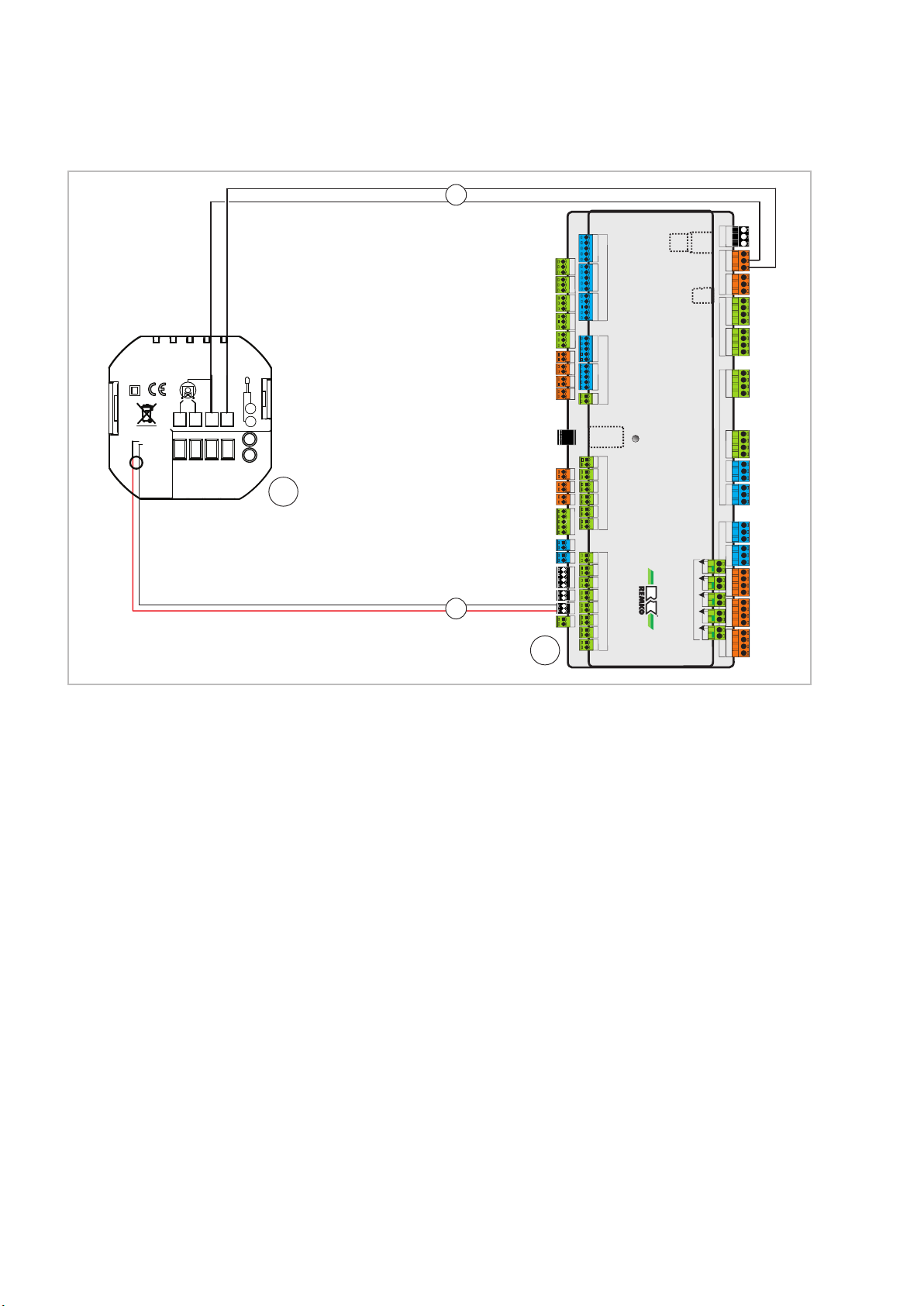
7 Installation
DANGER!
All electrical installation work is to be performed
by specialist companies. Disconnect the power
supply when connecting the electrical terminals.
The thermostat is suitable for a standard flushmounted socket.
Proceed with the installation as follows:
1. For installation, turn the round display clockwise to release the display from the mounting
plate.
6. Mount the display
.
2. Draw the ribbon cable out of the display to
avoid damage.
3. Connect the power supply to terminals 3+4.
4. Connect the 2-core communication cable to
the two cores, white and red.
erminals 1+2 can be used for actuation of a
T
heating cycle pump or valve.
5. Bolt the mounting plate to the flush-mounted
socket with the screws provided.
17

REMKO remote controls
8 Addressing the EC1
A maximum of three probes can be supplied with
mains voltage via the power supply of the REMKO
I/O module. If further remote controls are still to be
installed, they must be supplied with a separate
230 V mains voltage. Each probe, such as a room/
humidity probe or Smart-Control T
control must be assigned its own BUS address.
This address must be stored in the Smart Control
Touch at the corresponding parameter level of the
assigned heating/cooling cycle.
ouch remote
Expert level
¯
Settings
¯
Select heating cycle
¯
For example: unmixed cycle
Parameters in the selected cycle
Operating mode
Heating cycle mode
Fixed value
Heating curve adjustment
Cooling cycle mode
Fixed value
Cooling curve adjustment
Time program A
Fig. 7: Setting the BUS address
The BUS address for the Easy-Control room thermostat can be found in the expert level as param-
Ä
eter “c” in chapter
on page 14.
BUS address for room temperature/humidity
probe
Parameter BUS address
c "01 - 99"
For addressing the BUS address of the Easy-Control room thermostat, open the expert level as
described in chapter
on page 14. Under point “c” you can assign a BUS
address for your room thermostats. Make sure that
all components to which you assign an address
are assigned different addresses. If a room/
humidity probe and Easy-Control room thermostat
for example are assigned the same address, this
will result in malfunctions.
After the setting is entered, it is not necessary to
save the parameter. The data is accepted automatically.
‘Access to the expert level’
Ä
‘Access to the expert level’
Time program B
Time program C
Time program function
Room temperature reduction
Room temperature increase
☛ Room unit (OFF) ☚
for example: Easy-Control EC1
BUS address: Easy-Control EC1
Room temperature influence
Dew point monitoring
Dew point distance
Pump type
Min. pump speed A42 (%)
Max. pump speed A42 (%)
Min. pump speed A42 (rpm)
Max. pump speed A42 (rpm)
Pump during cooling
18

9 Index
A
Addressing of the probe .................. 18
Assembly ............................. 15
D
Dimensions ............................. 7
Disposal of equipment .....................6
E
Electrical wiring ......................... 16
Environmental protection ...................6
Expert level ............................ 14
I
Installation ..........................15
Intended use ............................ 5
, 17
O
Operation .............................. 9
R
Remote control display .................... 9
S
Safety
Dangers of failure to observe the safety
notes ............................... 4
General ............................. 4
Identification of notes ................... 4
Notes for inspection .................... 5
Notes for installation ....................5
Notes for maintenance .................. 5
Personnel qualifications ................. 4
Safety notes for the operator ............. 5
Safety-conscious working ................4
Unauthorised modification ...............5
Unauthorised replacement part manufacture
Scope of delivery ........................ 8
Set time programs .......................10
Setting the time programs ................. 10
Settings ................................9
. 5
T
Technical data ........................... 7
Terminal layout ......................... 16
U
Unit data ............................... 7
Unit description .......................... 8
Unit dimensions ......................... 7
W
Warranty ............................... 5
19

REMKO QUALITY WITH SYSTEMS
Air-Conditioning | Heating | New Energies
Telephone +49 (0) 5232 606-0
Telefax +49 (0) 5232 606-260
E-mail info@remko.de
URL www.remko.de
REMKO GmbH & Co. KG
Klima- und Wärmetechnik
Im Seelenkamp 12
32791 Lage
Hotline within Germany
+49 (0) 5232 6 06-0
Hotline International
+49 (0) 5232 606-130
We reserve the right to make technical changes, and provide no guarantee as to the accuracy of this data!
 Loading...