

REMKO
DIFFERENTIAL PRESSURE
OVERFLOW VALVE
Operation · Technology
Edition GB-B08

Contents
Safety notes
Environmental protection and recycling
Warranty
Intended use
Description
Installation
Before commissioning
Exploded view of the unit
Technical data
4
5
5
5
6
6-7
11
8
9
Made by REMKO
Read these operating instructions carefully
before commissioning / using the device!
These instructions are an integral part of the unit and must
always be kept in the vicinity of the installation location or
on the unit itself.
This operating manual is a translation of the German original.
Subject to modifications; no liability accepted for errors or
misprints!
3

REMKO OVERFLOW VALVE
Safety notes
Carefully read the operating manual
before placing the unit in service for
the first time. It provides useful tips
and notes ! such as hazard warnings
to prevent injury and material damage.
Failure to follow the directions in this
manual can endanger persons, the
environment and the equipment itself
and will void any claims for liability.
■ Keep this manual in the vicinity of
the units.
■ Only qualified personnel may set up
and install the units and components.
■ The set-up, connection, and operation
of the unit and its components
must take place in accordance with
the operating conditions stipulated
in this manual and comply with all
applicable local regulations.
■ Modification of the units and
components supplied by REMKO
is not permitted and can cause
malfunctions.
■ Units and components may not be
operated in areas where there is an
increased risk of damage. Observe
the minimum clearances.
■ The electrical supply is to be adapted
to the requirements of the units.
■ The operational safety of units and
components is only assured if they are
fully assembled and used as intended.
Safety devices may not be modified
or bypassed.
■ Do not operate units or components
if there are obvious defects or signs
of damage.
■ The units and components must
be kept at a safe distance from
flammable, explosive, combustible,
aggressive and dirty areas or
atmospheres.
■ Installation, repair and maintenance
work may only be carried out
by authorised specialists. Visual
inspections and cleaning can be
performed by the operator as long
the equipment is disconnected from
the power.
■ Take appropriate precautions when
performing installation, repair or
maintenance work or cleaning
the unit to make sure the unit does
not pose a danger to persons.
4

Environmental protection and recycling
Disposing of packaging
All products are packed for transport in
environmentally friendly materials. You
can make a valuable contribution to
reducing waste and to sustaining raw
materials by only disposing of packaging
at approved collection points.
Disposal of
components
The manufacturing process for the units
is subject to continuous quality control.
Only high-grade materials are used, the
majority of which can be recycled. You
can also contribute to environmental
protection by only disposing of
components in accordance with local
regulations and in an environmentally
safe manner, e.g. through authorised
disposal and recycling specialists or at
collection points.
Intended
use
The overflow valve ensures that the
minimum flow volume is maintained.
Any different or additional use is a nonintended use.
The manufacturer/supplier assumes no
liability for damages arising from a nonintended use. The user bears the sole risk
in such cases.
Using the equipment as intended also
includes working in accordance with
the operating manual and installation
instructions and complying with
the maintenance requirements.
Warranty
The warranty conditions are listed in the
"General terms and conditions".
Please contact your direct contract
partner first.
5

REMKO OVERFLOW VALVE
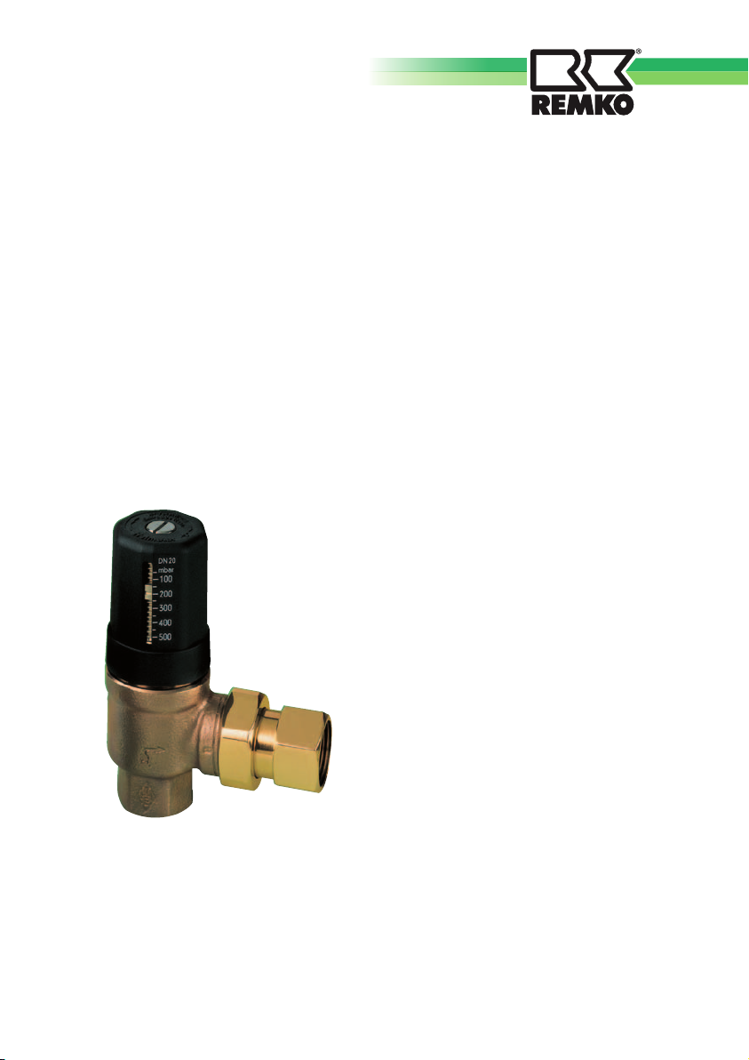
Description
The overflow valve operates
proportionally as a function of
the differential pressure and ensures
that the minimum flow volume is
maintained.
It is designed for pump hot water
heating systems.
The overflow valve prevents undesirably
high increases of the delivery height and
maintains the delivery rate.
In heat pump heating systems, this
maintains the minimum circulation water
volume.
The housing is made of corrosionresistant brass.
The setting and adjusting scale can be
read directly.
Equipped with an internal and
generously sized stainless steel setpoint
spring, the overflow valve is extremely
precise.
The continuously variable adjustment is
secured to prevent unauthorised persons
from making adjustments.
Installation
Installation
Installation is possible independent of
the position.
■ As much as possible, install
the overflow valve upright, i.e. with
the hand wheel cap facing upwards.
This ensures that it can be read easily.
■
Take the
The control is managed inside the valve.
External control lines are not needed.
■
Run the
not lose pressure, i.e. as short as
possible, generously sized and
without avoidable resistance.
This improves the overflow valve's
effectiveness.
direction of flow
bypass line so that it does
The connections have an inside thread
on the inlet side and a flat sealing fitting
on the outlet side.
It has a 1" design.
6

Optimum (upright) installation of the overflow valve
Setting and adjusting the overflow valve
The overflow valve is calibrated in the
factory and preset to a cracking pressure
of 200 mbar (2 m WS).
If it should be necessary to change the
default setting, proceed as follows:
1. Loosen the lock screw.
Using the hand wheel cap, the
cracking pressure can then be
adjusted continuously in a range
between 50 mbar and 500 mbar. The
desired value can be read directly
from the scale on the hand wheel
cap.
A setting and adjustment chart is not
needed.
NOTE
The overflow valve must be set
so that the minimum flow value
is maintained in a closed heating
circuit.
2. Using the lock screw, then secure
the selected position to prevent
accidental adjustment.
NOTE
Installation may only be performed
by authorised specialists.
7

REMKO OVERFLOW VALVE
Exploded view of the unit
Overflow valve
Locking screw
Snap ring
Display nut
Locking washer
O-ring
Hand wheel cap
Set point spring
Top piece
Plate
Housing
Disc
Spindle nut
Spindle
8

Technical data
Unit type Overflow valve
Inside thread, inlet connection Inches 1
Inside thread, outlet connection Inches 1
Cracking pressure range mbar 50-500
Cracking pressure range, default mbar 200
EDP no. 260080
We reserve the right to modify the dimensions and design as part of the ongoing technical development process.
9

REMKO OVERFLOW VALVE
Notes
10

11

REMKO INTERNATIONAL
... and also right in your neighbourhood!
Take advantage of our experience and advice
REMKO GmbH & Co. KG
Klima- und Wärmetechnik
Im Seelenkamp 12 D-32791 Lage
Postfach 1827 D-32777 Lage
Telephone +49 5232 6 06-0
Fax +49 5232 6 06-2 60
e-mail info@remko.de
Website www.remko.de
We reserve the right to make technical changes and provide no warranty as to the accuracy of this data!
 Loading...