

REMKO EMT 100, EMF 100, CMT 180, CMF 180, CMT 120 Assembly And Operating Instructions Manual
...
Assembly and operating instructions
Assembly and operating instructions
REMKO EMF / EMT 100
Inverter heat pumps
2011-01-001, 1, en_GB
Read the instructions prior to performing any
task!

Read these operating instructions carefully before commissioning / using this device!
These instructions are an integral part of the system and must
always be kept near or on the device.
Subject to modifications; No liability accepted for errors or misprints!
Installation and operating instructions (translation of the original)

Table of contents
1 Safety and user notes........................................................................................................................... 5
1.1 General safety notes....................................................................................................................... 5
1.2 Identification of notes...................................................................................................................... 5
1.3 Personnel qualifications.................................................................................................................. 5
1.4 Dangers of failure to observe the safety notes................................................................................ 5
1.5 Safety-conscious working............................................................................................................... 6
1.6 Safety notes for the operator........................................................................................................... 6
1.7 Safety notes for installation, maintenance and inspection.............................................................. 6
1.8 Unauthorised modification and replacement part manufacture....................................................... 6
1.9 Intended use................................................................................................................................... 6
1.10 Warranty........................................................................................................................................ 7
2 Technical data....................................................................................................................................... 8
2.1 Units data........................................................................................................................................ 8
2.2 Unit dimenions outdoor module...................................................................................................... 9
2.3 Unit dimensions indoor module..................................................................................................... 10
2.4 Heat pump service limits in monovalent mode ............................................................................. 12
2.5 Pump-characteristic curves, indoor module charging pump......................................................... 12
2.6 Sound pressure level.................................................................................................................... 13
2.7 Overall sound pressure levels for outdoor module EMF/EMT 100............................................... 14
2.8 Characteristic curves..................................................................................................................... 15
3 Structure and Function....................................................................................................................... 18
3.1 The heat pump in general............................................................................................................. 18
3.2 EMF Series................................................................................................................................... 24
3.3 EMT Series................................................................................................................................... 24
4 Installation instructions...................................................................................................................... 25
4.1 General mountig instructions........................................................................................................ 25
4.2 Installation, mounting indoor module............................................................................................ 27
4.3 Installation, mounting outdoor module.......................................................................................... 28
5 Hydraulic connection.......................................................................................................................... 31
6
Corrosion protection.......................................................................................................................... 33
7 Connection of refrigerant lines.......................................................................................................... 34
7.1 Connection of refrigerant lines...................................................................................................... 34
7.2 Commissioning the refrigeration system....................................................................................... 35
8 Electrical connection.......................................................................................................................... 38
8.1 Electrical connection..................................................................................................................... 38
8.2 Structure electrical connection...................................................................................................... 41
8.3 Terminal block / legend................................................................................................................. 42
8.4 Connection diagram, terminal configuration.................................................................................. 44
8.5 Circuit diagrams............................................................................................................................ 45
8.6 Auxiliary relays and contactor function.......................................................................................... 53
9 Commissioning................................................................................................................................... 54
9.1 Control panel................................................................................................................................. 54
9.2 Notes for commissioning .............................................................................................................. 55
9.3 Heat pump manager Multi-Talent Plus (heat flow meters)............................................................ 56
3

REMKO EMF / EMT
10 Care and maintenance........................................................................................................................ 58
11
Troubleshooting and customer service............................................................................................ 59
12 Exploded view and spare parts......................................................................................................... 62
12.1 Exploded view and spare parts list outdoor module.................................................................... 62
12.2 Exploded view and spare parts list indoor module...................................................................... 64
13 Temporary shut-down........................................................................................................................ 69
14 Transport and packaging................................................................................................................... 69
15 Environmental protection and recycling.......................................................................................... 69
16 EC- Declaration of Conformity........................................................................................................... 70
17 General terms...................................................................................................................................... 71
18 Index..................................................................................................................................................... 74
4

1 Safety and user notes
1.1 General safety notes
Carefully read the operating manual before commissioning the units for the first time. It contains
useful tips and notes such as hazard warnings to
prevent personal injury and material damage.
Failure to follow the directions in this manual not
only presents a danger to people, the environment
and the system itself, but will void any claims for
liability.
Keep this operating manual and the refrigerant
data sheet near to the units.
1.2
This section provides an overview of all important
safety aspects for proper protection of people and
safe and fault-free operation.The instructions and
safety notes contained within this manual must be
observed in order to prevent accidents, personal
injury and material damage.
Notes attached directly to the units must be
observed in their entirety and be kept in a fully
legible condition.
Safety notes in this manual are indicated by symbols. Safety notes are introduced with signal words
which help to highlight the magnitude of the danger
in question.
Contact with live parts poses an immediate
danger of death due to electric shock. Damage
to the insulation or individual components may
pose a danger of death.
Identification of notes
DANGER!
CAUTION!
This combination of symbol and signal word
warns of a potentially hazardous situation,
which if not avoided may cause slight or minor
injury.
NOTICE!
This combination of symbol and signal word
warns of a potentially hazardous situation,
which if not avoided may cause material and
environmental damage.
This symbol highlights useful tips and recommendations as well as information for efficient
and fault-free operation.
1.3 Personnel qualifications
Personnel responsible for operation, maintenance,
inspection and installation must be able to demonstrate that they hold a qualification which proves
their ability to undertake the work.
DANGER!
Inadequate qualifications may pose a danger
of death! Improper handling may cause serious
personal injury and material damage.
DANGER!
This combination of symbol and signal word
warns of a situation in which there is immediate
danger, which if not avoided may be fatal or
cause serious injury.
WARNING!
Therefore:
- Installation, commissioning and maintenance,
repairs must be carried out by a professional
certified personnel.
- In case of doubt, consult a qualified professional.
1.4 Dangers of failure to observe the safety notes
This combination of symbol and signal word
warns of a potentially hazardous situation,
which if not avoided may be fatal or cause
serious injury.
5
Failure to observe the safety notes may pose a risk
to people, the environment and the units. Failure to
observe the safety notes may void any claims for
damages.
In particular, failure to observe the safety notes
may pose the following risks:

REMKO EMF / EMT
n The failure of important unit functions.
n The failure of prescribed methods of mainte-
nance and repair.
n Danger to people on account of electrical and
mechanical effects.
1.5
The safety notes contained in this installation and
operating manual, the existing national regulations
concerning accident prevention as well as any
internal company working, operating and safety
regulations must be observed.
1.6
The operational safety of the units and components is only assured providing they are used as
intended and in a fully assembled state.
n The units and components may only be set up,
n Protective covers (grille) over moving parts
n Do not operate units or components with
n Contact with certain unit parts or components
n The power supply should be adapted to the
n Tripped circuit breakers may only be replaced
n In the event of defects that endanger the
n The units and components must not be
n Regulations such as the regional building regu-
n In the event that refrigerant has leaked from
n All housing parts and device openings, e.g. air
n The units must be inspected by a service tech-
Safety-conscious working
Safety notes for the operator
installed and maintained by qualified personnel.
must not be removed from units that are in
operation.
obvious defects or signs of damage.
may lead to burns or injury.
requirements of the units.
by those of identical construction.
operational safety of the units, operation must
be discontinued.
exposed to any mechanical load, extreme
levels of humidity or direct exposure to sunlight.
lations and the Water Ecology Act must be
observed.
the indoor unit, the room must be properly ventilated before the unit is re-started. Otherwise
there is danger of suffocation.
inlets and outlets, must be free from foreign
objects, fluids or gases.
nician at least once annually. Visual inspections and cleaning may be performed by the
operator when the units are disconnected from
the mains.
1.7 Safety notes for installation, maintenance and inspection
The operator must ensure that all installation,
maintenance and inspection work is carried out by
authorised and qualified personnel who have thoroughly read the installation and operating manual.
The procedure for shutting down the units as
described in the installation and operating manual
must be followed in its entirety.
All safety and protection devices must be reattached and restored to working order immediately upon completion of the work.
n Appropriate hazard prevention measures must
be taken to prevent risks to people when performing installation, repair, maintenance or
cleaning work on the units.
n The setup, connection and operation of the
units and its components must be undertaken
in accordance with the usage and operating
conditions stipulated in this manual and comply
with all applicable regional regulations.
n Units may only be mounted at the points pro-
vided for this purpose at the factory. The units
may only be secured or mounted on stable
structures, walls or floors.
n Mobile units must be set up securely on suit-
able surfaces and in an upright position. Stationary units must be permanently installed for
operation.
n The units and components should not be oper-
ated in areas where there is a heightened risk
of damage. Observe the minimum clearances.
n The units and components must be kept at an
adequate distance from flammable, explosive,
combustible, abrasive and dirty areas or
atmospheres.
1.8 Unauthorised modification
and replacement part manufacture
Modifications or changes to units and components
are not permitted and may cause malfunctions.
Safety devices may not be modified or bypassed.
Original replacement parts and accessories
authorised by the manufactured ensure safety. The
use of other parts may invalidate liability for
resulting consequences.
1.9
Depending on the model, the equipment and the
additional fittings with which it is equipped is only
intended to be used as an air-conditioner for the
purpose of cooling or heating the air in an
enclosed room.
Intended use
6

Any different or additional use shall be classed as
non-intended use. The manufacturer/supplier
assumes no liability for damages arising from such
use. The user bears the sole risk in such cases.
Intended use also includes working in accordance
with the operating and installation instructions and
complying with the maintenance requirements.
Under no circumstances should the threshold
values specified in the technical data be exceeded.
1.10
For warranty claims to be considered, it is essential
that the ordering party or its representative complete and return the "certificate of warranty" to
REMKO GmbH & Co. KG at the time when the
units are purchased and commissioned.
The warranty conditions are detailed in the "General business and delivery conditions". Furthermore, only the parties to a contract can conclude
special agreements beyond these conditions. In
this case, contact your contractual partner in the
first instance.
Warranty
7

REMKO EMF / EMT
2 Technical data
2.1 Units data
Series EMF 100 EMT 100
Function Heating or Cooling
System Split-Air/Water
Heat pump manager Multitalent or Multitalent Plus
Storage tank for hydraulic decoupling of volumetric flows optional Series 160 l
Electric booster heating / rated output kW optional Series / 9,0
Water heating optional Series
Heating output min / max kW 1,1 - 10,2
Heating output / compressor frequency / COP 1) for A10/
W35
Heating output / compressor frequency / COP 1) for A7/
W35
Heating output / compressor frequency / COP 1) for A2/
W35
Heating output / compressor frequency / COP 4) for A2/
W35
Heating output / compressor frequency / COP 1) for A-7/
W35
Cooling output min. / max. kW 1,6 - 9,1
Cooling output / compressor frequency / EER 2) for A35/
W7
Cooling output / compressor frequency / EER 2) for A27/
W7
Service limits, heating °C -18 bis +45
Service limits, cooling °C +15 bis +45
Supply-temperature, heating water °C up to +50
Min. Supply-temperature, cooling °C up to +7
kW/Hz/COP 8,7 / 58 / 4,9
kW/Hz/COP 8,1 / 58 / 4,4
kW/Hz/COP 4,7 / 58 / 3,0
kW/Hz/COP 6,3 / 73 / 2,5
kW/ Hz/COP 4,5 / 58 / 2,7
kW/Hz/COP 6,2 / 3,5 / 74
kW/Hz/COP 6,4 / 3,9 / 74
Refrigerant / pre-charge quantity outdoor unit -- / kg
Refrigerant / pre-charge quantity for up to 10 m length of
ordinary pipe
Refrigerant connection Inches ¼ / ⅝
Max. permissible single refrigerant pipe length. m 50
Max. permissible single refrigerant pipe height. m 30
Power supply V / Hz 230/1~ / 50
Starting current A 12,5
Rated current consumption for A7/W35 A 13
Rated power consumption for A7/W35 kW 1,84
g / m 30
R 410A2)/ 1,9
8

Series EMF 100 EMT 100
61050
12
880 52.9
364
17.6
395
796.5
Power factor by A7/W35 (cosφ) -- 0,98
Fuse protection (outdoor unit) A slow-acting 20
Rated water flow (according to EN 14511, at ∆t 5 K) m³/h 1,42
Pressure-loss at the condenser at rated flow kPa 5,4
Airflow volume outdoor module m³/h 2760
Max. operating pressure, water bar 3,0
Hydraulic connection, supply / return Inches 1“ AG
Sound-pressure level, LpA 1m (outdoor unit)
3)
dB(A) 54/40
Sound-power level in accordance with DIN EN
dB(A) 64,1
12102:2008-09 and ISO 9614-2
Dimensions, indoor unit (height/width/depth) mm 800/550/545 1760/550/670
Dimensions, outdoor unit (height/width/depth) mm 800 / 880 / 312
Enclosure class outdoor unit -- IP 24
Weight indoor module kg 47 135
Weight outdoor module kg 57
1)
COP = coefficient of performance or performance number according to EN 14511
2)
Contains greenhouse gas according to Kyoto protocol
3)
Clear-field distance: 5m
4)
COP = coefficient of performance number according to EN 14511, during alternative compressor fre-
quency of the inverter
2.2
Unit dimenions outdoor module
Fig. 1: Dimenions outdoor module EMF/ EMT 100
9

REMKO EMF / EMT
2.3 Unit dimensions indoor module
Unit dimensions indoor module EMF 100
220
160
255
140
180
Fig. 2: dimensions indoor module series EMF
1
2
3
4
5
6
7
8
Fig. 3: Pipe-socket arrangement
1 Refrigerant pipe, 3/8"
2 Refrigerant pipe, 5/8”
3 Hot-water return, 1” AG
4 Hot-water inlet, 1” AG
5 Sockets for safety assembly
6 Condensate-drain socket AD=22
7 Opening for installing the E-heater controller
8 Fill- and drain valve
255
200
85
155
235
50
220
Fig. 4: Pipe-outlet spacing
185
260
150
10

Unit dimensions indoor module EMT 100
2
3
1
550
180
100
60
1
3
2
4
6
1670
5
935
910
550
795
605
670
Fig. 5: dimensions indoor module EMT 100 (Tilt height: 1,900 mm)
1 Supply, warm water
2 Supply, heating
3 Return
4 Refrigerant pipes
5 Sockets for safety condensate drain
6 Overall dimensions: max. 1760
60
235
155
80
260
11

20,0
25,0
30,0
35,0
40,0
45,0
50,0
55,0
60,0
-20 -15 -10 -5 0 5 10 15 20 25 30 35 40 45 50
Source temperature [°C]
Inlet temperature [°C]
ALPHA2 25-40 (A)(N)
ALPHA2 32-40
REMKO EMF / EMT
2.4 Heat pump service limits in monovalent mode
Fig. 6: Service limits and test points EMF / EMT 100
Note: The left temperature value in the diagram refers to the Supply-temperature heating water and the
lower refers the outdoor air temperature.
2.5 Pump-characteristic curves, indoor module charging pump
Fig. 7: Pump-characteristic curves, idoor module
EMF / EMT 100
Level Output [W] Current [A] Motor protection
min. 5 0,05 Rotor current-proof
max. 22 0,19 Rotor current-proof
12

2.6 Sound pressure level
1m1m
5m
10m
1m
5m
10m
Fig. 8: Distance-dependent sound pressure level for the outdoor unit in relation to installation type, in accordance with the drawing
Distance-dependent sound pressure level
Heat pump out-
door unit
Sound power
level according
to ISO 9614-2
EMF / EMT 100 62,4 dB(A)
Installation type,
in accordance
1m 5m 10m 15m
with the drawing
In free field 54,4 dB(A) 40,4 dB(A) 34,4 dB(A) 30,9 dB(A)
In front of a wall 57,4 dB(A) 43,4 dB(A) 37,4 dB(A) 33,9 dB(A)
13

REMKO EMF / EMT
2.7 Overall sound pressure levels for outdoor module EMF/EMT 100
Excluded range
Cursor: (A) Power=62,4 dB
Fig. 9: Overall sound pressure level L
Middle frequency [Hz] 25 31,50 40 50 63 80 100 125 160
LI [dBA] (18,4) (25,7) (24,0) (27,4) (26,5) (21,0) 29,0 39,7 33,9
LWo [dBA] (27,2) (34,5) (32,7) (36,2) (35,3) (29,8) 37,8 48,5 42,7
Output A-bew
P
WP143 overall device
FPI [dB] -(5,6) (3,8) -(2,1) -(5,9) (1,4) (5,7) 5,4 4,3 4,3
Middle frequency [Hz] 200 250 315 400 500 630 800 1000 1250
LI [dBA] 34,4 43,3 51,0 39,4 40,1 41,3 42,3 39,0 36,7
LWo [dBA] 43,2 52,1 59,8 48,2 48,8 50,0 51,1 47,8 45,5
FPI [dB] 6,1 5,6 4,6 5,1 4,8 3,9 4,1 5,0 5,3
Middle frequency [Hz] 1600 2000 2500 3150 4000 5000 6300 8000 10000
LI [dBA] 35,5 32,9 31,6 29,5 25,1 21,1 16,7 (16,1) (14,7)
LWo [dBA] 44,3 41,6 40,4 38,3 33,9 29,9 25,5 (24,9) (23,4)
FPI [dB] 5,5 6,0 5,8 6,0 7,0 8,6 11,2 (9,9) (9,9)
Determination of sound power conforms to accuracy class 2, the standard deviation of the o. a. A-valued
sound-power levels amounts to 1.5 dB.
LWo: Sound power level radiated by the outdoor
unit
FPI: Correction value with regard to the environment
LI: Sound intensity
14

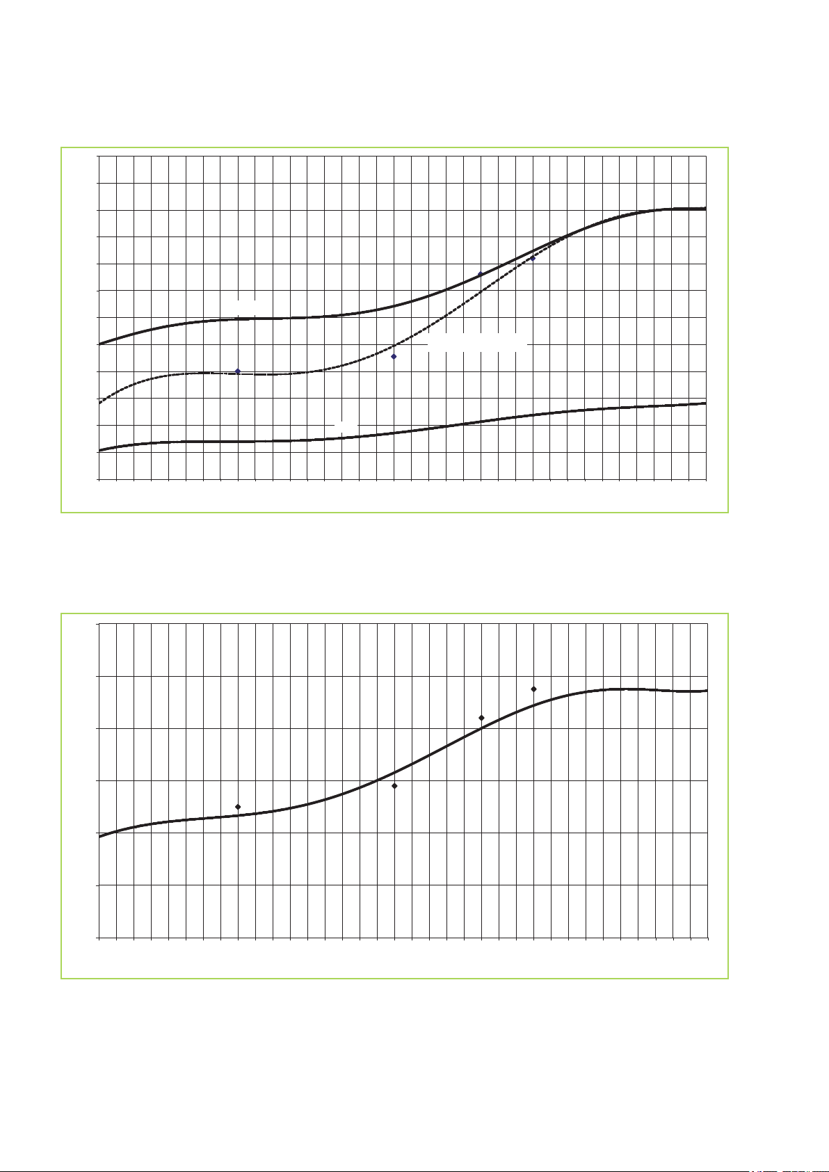
2.8 Characteristic curves
0
1
2
3
4
5
6
7
8
9
10
11
12
-15 -14 -13 -12 -11 -10 -9 -8 -7 -6 -5 -4 -3 -2 -1 0 1 2 3 4 5 6 7 8 9 10 11 12 13 14 15 16 17 18 19 20
Outdoor temperature [°C]
Heating output [kW]
n-min
n-max
Rated frequency 58Hz
0
1
2
3
4
5
6
-15 -14 -13 -12 -11 -10 -9 -8 -7 -6 -5 -4 -3 -2 -1 0 1 2 3 4 5 6 7 8 9 10 11 12 13 14 15 16 17 18 19 20
Outdoor temperature [°C]
COP [-]
Rated frequency 58 Hz
Heat output at an inlet temperature of 35 °C
Fig. 10: Heat output EMF/ EMT 100 at an inlet temperature of 35 °C
COP at an inlet temperature of 35 °C
Fig. 11: COP EMF/EMT 100 at an inlet temperature of 35 °C
15
0
1
2
3
4
5
6
7
8
9
10
11
12
-15 -14 -13 -12 -11 -10 -9 -8 -7 -6 -5 -4 -3 -2 -1 0 1 2 3 4 5 6 7 8 9 10 11 12 13 14 15 16 17 18 19 20
Outdoor temperature [°C]
Heating output [kW]
n-min
n-max
Rated frequency 58Hz
0
1
2
3
4
5
6
-15 -14 -13 -12 -11 -10 -9 -8 -7 -6 -5 -4 -3 -2 -1 0 1 2 3 4 5 6 7 8 9 10 11 12 13 14 15 16 17 18 19 20
Outdoor temperature [°C]
COP [-]
REMKO EMF / EMT
Heat output at an inlet temperature of 45 °C
Fig. 12: Heat output EMF/ EMT 100 at an inlet temperature of 45 °C
COP at an inlet temperature of 45 °C
Fig. 13: COP EMF/EMT 100 at an inlet temperature of 45 °C
16

Heat output at an inlet temperature 55 °C
n-max.
0
1
2
3
4
5
6
7
8
9
10
11
12
-15 -14 -13 -12 -11 -10 -9 -8 -7 -6 -5 -4 -3 -2 -1 0 1 2 3 4 5 6 7 8 9 10 11 12 13 14 15 16 17 18 19 20
Outdoor temperature [°C]
Heating output [kW]
n-min.
0
1
2
3
4
5
-15 -14 -13 -12 -11 -10 -9 -8 -7 -6 -5 -4 -3 -2 -1 0 1 2 3 4 5 6 7 8 9 10 11 12 13 14 15 16 17 18 19 20
Outdoor temperature [°C]
COP [-]
Fig. 14: Heat output EMF/ EMT 100 at an inlet temperature of 55 °C
COP at an inlet temperature of 55 °C
Fig. 15: COP EMF/EMT 100 at an inlet temperature of 55 °C
17

REMKO EMF / EMT
3 Structure and Function
3.1 The heat pump in general
Arguments for Remko
n Low heating costs in comparison to oil and gas
n Heat pumps represent a contribution to envi-
ronmental protection
75%* of the heat
comes from the air,
free of charge
75%
freesolar energy
from the air
*
n Lower CO
gas heating
n All models are able to cool as well as heat
n Low noise-level of the outdoor unit
n Flexible installation due to split system design
n Negligible maintenance costs
emissions in comparison to oil and
2
electrical drive energy
25%
Fig. 16: Free heat
* The relationship can vary depending on outdoor temperature and operating conditions.
Economical and environmentally-conscious
heating
The burning of fossil-based energy sources in
order to generate power creates severe consequences for the environment. A high percentage of
fossil fuels is also problematic due to the limited
resources of oil and gas and the price increases
resulting from this. For this reason, many people
today are thinking both economically and environmentally-consciously in terms of heating. The
application of heat pump technology enables both
of these concepts to be combined. It makes use of
the energy which is permanently available in the
air, water and soil and converts it into usable
heating energy by means of inputting electrical
energy. Yet in order to generate heat equivalent to
4kWh, only 1kWh of electricity is required. The rest
is made available free-of-charge by the environment.
*
Heat source
There are essentially three heat sources that heat
pumps can derive energy from. air, soil and
groundwater. Air heat pumps have the advantage
that air as a source heat is available everywhere in
unlimited quantities that can be used free of
charge. A disadvantage is that the outside air is at
its coldest when the heat requirement is greatest.
Brine heat pumps extract energy from the soil. This
is undertaken in serpentine pipe networks which
are laid approx. 1m deep or placed by means of
drilling. The disadvantage is the large space
requirements for the serpentine pipe networks or
the high cost of drilling. A long-term cooling of
the soil is also a possibility.
Water heat pumps require two wells in order to
obtain heat from the groundwater, one supply well
and one dry well. The development of this source
is not possible everywhere, it is expensive and
requires planning permission.
Heating
18

Function of the heat pump
A heat pump is a device which makes use of a
working medium to absorb ambient heat under low
temperatures and transports this heat to a place
where it can be of use for heating purposes. Heat
pumps work according to the same principles as a
refrigerator. The difference is that heat, the byproduct of the refrigerator, is the goal of the heat
pump.
The main components of the cooling circuit consist
of an evaporator, a compressor, a condenser and
an expansion valve. In a finned evaporator,
the refrigerant evaporates both because of lower
pressure and because of lower heat-source temperatures through absorption of energy from the
environment. In the compressor, the refrigerant is
brought to a higher pressure and temperature by
the application of electrical energy. Next, the hot
refrigerant gas reaches the condenser, a plate
heat-exchanger. Here the hot gas condenses,
Outdoor area
transferring heat to the heating system. The liquefied refrigerant then expands and cools in a flow
regulator, the expansion valve. Then the refrigerant flows into the evaporator once more and the
cycle is complete.
For control, a heat-pump manager is included
which ensures the independent operation of all
safety devices. The water-circulation system of the
Series EMF consists of a charging pump, plate
heat-exchangers, dirt traps, a manometer, fill- and
drain valves, an automatic air-bleeder and flow
monitor.
The EMT series has, in addition, a 3-way switching
valve and a buffer storage.
Wall- and floor consoles, condensate pans, condensate-pan heating, a 3-way switching valve, a
bypass valve and other sensors are available as
accessories.
Indoor area
Condensing
Evaporation
Decompression
Heating pump outdoor unit
Fig. 17: Functional diagram heating inverter heat pump
Liquefying
Heating pump indoor unit
19

REMKO EMF / EMT
Heat pump modes
Heat pumps can work in various operating modes.
Monovalent
The heat pump the only source of heat for a
building all year round. This mode is particularly
suitable for heating plants with low supply-water
temperatures and is primarily used in combination
with brine/water and water/water heat pumps.
Single energy source
The heat pump has an E-heater to handle peak
loads. The heat pump covers the majority of the
required heating power. Occasionally, when it is
extremely cold outside, an electrical boosterheating system switches on as required in order to
support the heat pump.
Bivalent parallel
The heat pump provides the entire heating energy
down to a predetermined outdoor temperature. If
the temperature drops below this value, a second
heat source switches on to support the heat pump.
There is a distinction to be made here between
alternative operation with oil- or gas heat and
regenerative operations with solar energy or
wood-fired heating. This mode is possible for all
heating systems.
Layout
A precise calculation of the building's heating load
according to EN 12831 is required for the design
and dimensioning of a heating system. However,
approximate requirements can be determined
based on the year of construction and the type of
building. The table
approximate specific heating loads for a number of
building types. The required heating system output
can be calculated by multiplying the area to be
heated with the given values
For a precise calculation, various factors must be
considered. The transmission-heat requirement,
the infiltration heat-loss and an allowance for water
heating comprise the total heating output which the
heating system must provide.
The total area of the floor surfaces, exterior wall
windows, doors and roofing is required in order to
determine the transmission heat requirement. In
addition, information about the materials used in
the building is required, as these lead to extremely
Ä
on page 21 shows the
varied thermal transmission coefficients (the so
called K value). Also required are the room temperature and the standard outdoor temperature,
that is, the lowest outdoor-temperature on average
that will occur during the year. The equation for
calculating the transmission-heat requirement is
Q=A x U x (tR-tA) and must be calculated sepa-
rately for all room-enclosure surfaces.
The infiltration heat requirement takes into consideration how often the heated room air is
exchanged for cold external air. The room volume
(V), the air exchange frequency (n) and the specific heat capacity (c) of the air is also required in
addition to the room temperature and average low
temperature. The equation is: Q=V x n x c (tR-tA).
An approximate allowance for heating water - per
person according to VDI 2067: 0.2 kW
A residential home comprised of 150 m² livingspace and a heat requirement of 35 W/m² has
been selected for the example design. A total of
five persons live in the house. The heat load
amount to 5.2 kW. Adding a drinking water allowance of 0.2 kW results in a required heat output of
6.2 kW. Depending on the power company, an
additional charge must then be made in order to
factor in the service time-out period. The rating and
determination of the heat pump's balance-point
temperature derives graphically from the heat
pump's temperature-specification heat-output diagram. (In the example, 35 °C for a floor heatingsystem). Next, the heat load for the standard outdoor temperature (the lowest temperature of the
year locally) and the heat threshold are marked on
the graph. The outdoor-temperature-dependent
heating requirement, simplified here as a straightline relationship between heat-load and the start of
the heating season, is recorded in the graph of
heat-load curves. The intersection of the two
straight lines with the max. heat-load curve is
plotted on the X axis, where the balance-point temperature is read. (in the example, ca.-9°C) The
least load of the 2nd heat source is the difference
between heat load and the heat pump's maximum
heat output on these days. (In the example, the
capacity necessary to cover peak loads is ca. 2.5
kW.)
20

Diagram layout
Heat output at a supply temperature of 35°C
0
2
4
6
8
10
12
-15 -14 -13 -12 -11 -10 -9 -8 -7 -6 -5 -4 -3 -2 -1 0 1 2 3 4 5 6 7 8 9 10 11 12 13 14 15 16 17 18 19 20
Outdoor temperature [°C]
Heat output [kW]
Bivalent temperature
Minimum
performance
2. heat
source
Heat load
according to
DIN EN 12831
Heat load plus warm-water
requirements andservice
time-out period
Standard outdoor
temperature
Heating threshold for
old constructionaccording
to VDI 4650
Heat load
n-max
n-min
Rated frequency 78 Hz
Building type
Specific heating output in W/m
Passive energy house 10
Low-energy house built in 2002 40
According to energy conservation order regarding heat insulation
60
1995
Modern building constructed around 1984 80
Partially-renovated old building constructed pre-1977 100
Non-renovated old building constructed pre-1977 200
2
Fig. 18: Heat output diagramm of the heat pump EMF / EMT 100
Characteristics of REMKO inverter heat pumps
Outdoor air as a heat source
An air/water heat pump absorbs energy from the
outdoor air as its heat source and transmits this to
the heating system. They have the following
advantages over brine/water and water/water heat
pump systems:
21
n Can be used everywhere Air is available every-
where in unlimited quantities. For example, no
wells are required.
n No excavation required. No large areas are
required for soil collectors.
n Economical. Expensive drilling is not required.
n Excellent value for money and simple installa-
tion
n Particularly suitable for low-energy houses with
low inlet temperatures.
n Ideal for bivalent operation, in order to save
energy.

REMKO EMF / EMT
Split AC unit
The Remko inverter heat pump is a so called split
AC unit. This means that it consists of an outdoor
unit and an indoor unit, both of which are connected via refrigerant-carrying copper pipes. Thus
there are no water-carrying pipes laid from the
indoors to outdoors which need to be made frost
proof. The outdoor unit contains only the condenser, the evaporator and the expansion valve.
This means that the outdoor unit is considerably
smaller. The indoor module contains the system's
condenser and the connections for the heating network.
REMKO inverter technology
The heat pump's condenser is equipped with a
requirement-dependent speed control system. The
power control on conventional heat pumps provides only two states, either ON (full output) or
OFF (no output). The heat pump turns on below a
specified temperature and turns off when this temperature is reached. This kind of heat regulation is
very inefficient. Heat regulation in the Remko
inverter heat pump is modulated to the actual
need. The electronics system has an integrated
frequency-converter which serves to modify the
condenser speed and the speed of the blower as
required. The condenser works at a higher speed
when under full load than under partial load. The
lower speeds ensure a longer operational lifetime
for the components, improved coefficient of performance and lower noise. Lower speeds also
result in lower energy consumption (electricity) and
longer service life. I.e.: inverter heat-pumps will run
practically throughout the heating season. In all,
the highest efficiency possible.
Temperature
Conventional
Inverter
1/3
Fig. 19: Modern inverter technology
When it is switched on, the inverter only requires
one-third of the time of conventional systems
Minimal temperature fluctuations
mean energy savings
Time
22

Thanks to innovative inverter technology, this
heat pump will almost always operate by
adapting its heat output to the actual requirements of the heating season, and will in fact
turn itself off when heat is no longer needed.
The same applies in the opposite direction with
cooling.
Defrost by circulation reversal
At temperatures below about +5°C, humidity
freezes in the evaporator (outdoor module) and an
ice layer can form which reduces heat transfer
from the air to the refrigerant and to the air stream.
This layer of ice must be removed. A four-way
valve serves to reverse the refrigerant circuit, so
that the hot gas from the compressor flows through
the original evaporator and the ice that has formed
there can melt. The defrost process is not initiated
after a predetermined time; rather it is carried out
as required in order to save energy.
Cooling mode
Because of circuit reversal, cooling is also possible. In cooling mode, the components of the
refrigeration circuit are used to produce cold water
with which heat can be extracted from a building.
This can be accomplished with dynamic cooling or
passive cooling.
Under dynamic cooling the refrigerating capacity
is actively transferred to the indoor air. This is
undertaken by means of water-based fan convectors. In doing so, it is desirable that the inlet temperatures are under the dewpoint, in order to
transfer a higher refrigerating capacity and to
dehumidify the indoor air.
Passive cooling refers to the absorption of heat
via cooled floors, walls or ceiling surfaces. In doing
so, water-carrying pipes make the structural sections into thermically effective heat exchangers. In
order to achieve this, the refrigerant temperature
has to lie above the dew point, in order to avoid the
formation of condensation. Dewpoint monitoring is
required for this purpose.
We recommend dynamic cooling with fan convectors, in order to achieve increased thermal performance and in order to dehumidify the air on
muggy summer days. The advantage here is that
dewpoint monitoring is not required.
The comfort zone in the illustration below shows
which values for temperature and humidity are
considered comfortable for people. This range
should ideally be met when heating or air-conditioning buildings.
Relative humidity in %
uncomfortably
dry
10 12 14 16 18 20 22 24 26 28 30
Fig. 20: Comfort zone
uncomfortably
humid
comfortable
still comfortable
Room air temperature in °C
23

REMKO EMF / EMT
3.2 EMF Series
We offer two different indoor-unit designs. The
wall-mounted EMF Series is equipped with a circulation pump and a safety module on the water side.
Furthermore, an electrical booster heater can be
incorporated as an option. The EMF Series was
constructed for the addition of several heat
sources (bivalent installations or systems with
solar-heating equipment). External buffer storage
is always required, its size depending on the type
and the power of the second heat source. On the
one hand, the buffer storage prevents short runtimes for the heat pump and on the other hand,
that sufficient defrosting energy is available.
1
2
4
3
3.3 EMT Series
In addition, the indoor module of the EMT series is
fitted with a hot-water buffer storage. An electric
booster heater with a max. output of 9 kW is
standard. The hot-water buffer-storage has a
capacity of 150 litres and is integrated as a
hydraulic switch. As a result, the EMT Series is the
ideal equipment when the heat pump is intended
as the sole heat source (single energy-source operation).
1
2
4
5
9
3
6
7
8
5
10
6
7
8
9
Fig. 21: EMF-Series
1 Safety assembly
2 Pipe assembly for the installation of the
optional electric supplemental heating
3 Fold-down electrical control box
4 Terminal block for the temperature sensor
5 Relays with indicator lights
6 Terminal block X2 for external components,
such as heating-circuit pumps, etc.
7 Terminal block X1 for the power supply to the
indoor module
8 Mode switch
9 Identification plate and quick-reference guide
are found inside the hinged panel
Fig. 22: EMT Series
1 Safety assembly
2 Standard, built-in electric booster heater (6kW /
9kW)
3 Fold-down electrical control box
4 Terminal block X3 for the temperature sensor
5 Relais mit Kontrolleuchten
6 Terminal block X2 for external components,
such as heating-circuit pumps, etc.
7 Circuit breaker for the standard, built-in electric
booster heater
8 Terminal block X1 for the power supply to the
indoor module and to the electric booster
heater
9 Mode switch
Not illustrated: identification plate and quick-reference guide are found inside the removable centre
panel
24

4 Installation instructions
4.1 General mountig instructions
The indoor and outdoor modules have to be connected with refrigerant lines of dimensions 3/8" (ca. 16 mm)
and 5/8" (ca. 10 mm). A four-wire control cable has to be laid between the two modules. Both the indoor and
outdoor modules require a separate power supply.
Indoor area
Supply pipe for
hot-water tank (DN 25)
Indoor unit
EMT 100
Mains cable
Indoor unit
(3x1.5mm
Mains cable
Electric booster
heater
(5x2.5 mm
2
)
2
)
Common
Return pipe (DN 25)
Inlet for
Heating (DN 25)
Indoor unit
EMF 100
Mains cable
Indoor unit
(3x1.5mm
Mains cable
Electric booster
heater (optional)
(5x2.5 mm
Condensate drain
2
)
2
)
Hot-water supply
and return pipes
(DN 25)
Control cable (4x1 mm
Refrigerant lines
Outdoor unit EMT 100
Condensate drain
(Must be designed to be frost proof!)
Outdoor area
2
)
1
/4" and 5/8"
* Mains supply
230V/1~50Hz 25A
(3x4 mm
2
Fan
Fig. 23: System layout EMF 100 / EMT 100
Control cable (4x1 mm
Refrigerant lines
Outdoor unit EMF 100
)
Condensate drain
(Must be designed to be frost proof!)
2
)
1
/4" and 5/8"
* Mains supply
230V/1~50Hz 25A
(3x4 mm
Fan
2
)
25

2
1
4
3
REMKO EMF / EMT
WARNING!
All electric lines are in accordance VDE regulations to dimension and to lay.
General Information
n These instructions are to be observed when
installing the entire system.
n The device should be delivered as near as
possible to the site of installation in its original
packaging in order to avoid transport damage.
n The device is to be checked for visible signs of
transport damage. Possible defects must be
reported immediately to contract partners and
the forwarding agent.
n Suitable sites for installation are to be selected
with regard to machinery noise and the set-up
process.
n The shut-off valves for the refrigerant lines may
only be opened immediately before commissioning of the system.
n The exterior components are pre-filled with
refrigerant up to a distance of 10 meters from
the interior component. If the basic length of
the refrigerant line exceeds 10 metres, add
refrigerant.
n Establish all electrical connections in accord-
ance with the relevant DIN and VDE standards.
n The electrical power cables must be fastened
to the electrical terminals in the proper manner.
Otherwise there is a risk of fire.
n See that neither refrigerant or pipes that carry
water pass through living- or sleeping areas.
DANGER!
All electrical installation work is to be performed by speciality companies.
Wall breakthroughs
n A wall opening of at least 70 mm diameter and
10 mm slope from the inside to the outside
must be created.
n To prevent damage, the interior of the wall
opening should be padded or, for example,
lined with PVC pipe (see figure).
n After installation has been completed, use a
suitable sealing compound to close off the wall
breakthrough under observation of fire protection regulations (responsibility of customer).
NOTICE!
Open refrigerant pipes must be protected
against the introduction of moisture by means
of suitable caps or adhesive strips Refrigerant
pipes may not be kinked or compressed.
Refrigerant pipes may only be cut to length
with a suitable pipe cutter (use no hacksaws or
the like).
DANGER!
The installation of refrigerant equipment may
be undertaken only by trained specialist personnel!
Fig. 24: Wall breakthroughs
1. Liquid line
2. Control cable
3. Supply
4. Hot gas line
26

4.2 Installation, mounting indoor
module
Installation or setting up the indoor module
Indoor module EMF Series
n The wall bracket is to be attached to the wall
with the fasteners supplied and the indoor
module hooked onto it.
n The wall must possess sufficient load-bearing
capacity for the weight of the indoor module.
n Ensure that the wall bracket is installed level.
n The indoor module can be aligned precisely by
means of the adjustment screws on the back of
the housing.
n The indoor module is to be mounted in such a
way that all of the sides have sufficient space
for purposes of installation and maintenance. It
is equally important that there is sufficient
space above the device for installing the safety
assembly.
Fig. 25: Wall mounting EMF 100
Indoor module EMT Series
n The indoor module must be installed on a firm,
level surface.
n The surface must possess sufficient load-
bearing capacity for the weight of the indoor
module.
n The height-adjustable feet can be used to level
the indoor module precisely .
n The indoor module is to be mounted in such a
way that all of the sides have sufficient space
for purposes of installation and maintenance. It
is equally important that there is sufficient
space above the device for installing the pipes
and the safety assembly.
Fig. 26: Floor mounting EMT 100
WARNING!
Only fasteners suitable for the given application may be used.
27

REMKO EMF / EMT
4.3 Installation, mounting outdoor module
Outdoor module installation location
n The device may be attached only to a load-
bearing structure or wall. Ensure that the outdoor module is installed only vertically. The
installation site should be well ventilated.
n To minimise noise, install floor consoles with
vibration dampers and a considerable distance
from acoustically-reflective walls to minimise
noise.
n The minimum clearances specified on the next
page should be maintained when carrying out
the installation. These minimum distances
serve to ensure unrestricted air intake and
exhaust. Additionally, there must be adequate
space available for installation, maintenance
and repair.
n If the outdoor module is erected in an area of
strong winds, then the device must be protected against them (Fig. 27). The snow line is
to be observed during installation (Fig. 28).
n The outdoor module must always be installed
on vibration dampers. Vibration dampers prevent the transmission of vibrations through the
floor or walls.
n A heated, condensate catch-pan ensures that
condensation from the pan can drain off.
Ensure that the condensate is prevented from
freezing so that it can drain off (gravel,
drainage). The Water Ecology Act is to be
observed.
n If there is insufficient space under the device
for the refrigerant lines, then the pre-cut
recesses can be removed from the lower
enclosure-panel and the pipes guided through
these openings.
n During installation, add about 20 cm to the
expected snow depth to guarantee unimpeded
intake and exhaust of outdoor air year round.
(Fig. 28).
n The installation site of the outdoor module
should be agreed together with the operator
primarily so that operating noise is minimised
and not in terms of “short routes”. Thanks to
the split-design technology there are a great
deal of different installation options with almost
identical efficiency available.
Wind
Fig. 27: Protection from wind
Snow + 20 cm
Fig. 28: Protection from snow
NOTICE!
The site for the outdoor module must be
selected so that machinery noise that occurs
disturbs neither the residents nor the facility
operator. Observe the TA-noise specifications
as well as the table containing the drawings
relating to sound pressure levels.
28

Point of emissions Assessment level in accordance
1
2
3
4 5
6
>= 300
>= 1500
>= 1500 >= 300
>= 300
>= 300
>= 600
>= 600
>= 300
>= 1500
>= 2000
with TA noise
days in dB(A) nights in dB(A)
Industrial areas 70 70
Commercial areas 65 50
Core areas, village areas and mixed zones 60 45
General residential areas and small housing estates 55 40
Exclusively residential areas 50 35
Spa areas, hospitals and mental institutions 45 35
Isolated noise peaks of short duration may not exceed 30 dB(A) during the day and 20 dB(A) at night.
Minimum distances in mm for the outdoor modules EMF/EMT 100
Fig. 29: Minimum distances for installation of an outdoor module in mm for EMF/EMT 100
1 Against a wall, free flow air forward, backward
flow restriction
2 Against a wall, facing the wall air outlet, flow
front restriction
3 Freely between two walls, facing the wall outlet,
Sides: flow restrictions in front and rear
29
4 In a niche, free flow air to the front, rear and flow
restriction on both sides.
5 Before a covered wall, free flow air to the front,
rear and top of flow restrictions
6 Before a covered wall, air outlet towards wall,
flow restrictions behind and above

1 2
3
4
>= 1500
>= 300 >= 600 >= 600 >= 600
>= 300
>= 600 >= 600
>= 1500
>= 300
>= 1500 >= 3000>= 600 >= 300>= 3000
REMKO EMF / EMT
Fig. 30: Minimum distances for installation of several outdoor modules in mm for EMF/EMT 100
1 Against a wall, facing the wall air outlet, flow
front restriction
2 In a niche, free flow air to the front, rear and flow
restriction on both sides.
Condensate draining and ensured discharge
Condensate connection
If the temperature falls below the dew point, condensation will form on the finned condenser during heating
operation.
A condensate drip pan should be installed on the underside of the unit to drain any condensate.
n The condensate drain pipe to be installed on-site must be installed with a in cline of at least 2 % for good
drainage. If necessary, fit vapour density insulation.
n When operating the system at outdoor temperatures below 4 °C, care must be taken that the condensate
line is frost protected. The lower part of the housing and condensate pan are to be kept frost free in order
to ensure permanent drainage of the condensate. If necessary, fit supplementary pipe heating.
n After completed installation, check that the condensate drainage is unobstructed and ensure that the line
is leak tight.
Ensured discharge in the event of leakage
3 Between two walls, facing the wall outlet and
other modules, Sides: flow restrictions in front
and rear
4 Between two walls, air outlet towards wall, or the
external modules-free: flow restriction in front,
rear and internal modules on the sides.
NOTICE!
Local regulations or environmental laws, for example the German Water Resource Law (WHG), can
require suitable precautions to protect against uncontrolled draining in case of leakage to provide for safe
disposal of escaping refrigerator oil or hazardous media.
30
1
2
3
4
5
6
7
8
9
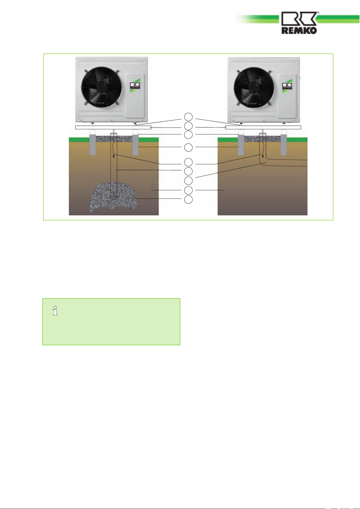
Fig. 31: Condensate- and melt-water drainage
1 Leg
2 Condensation catch pan
3 Floor bracket
4 Foundation
5 Condensate drainage-heating
5 Hydraulic connection
A separate interpretation of nominal flow rate
must be made for every system (see attachment: Technical Data).
n We recommend installing a buffer storage unit
as a hydraulic switch for hydraulically isolation
of the heating circuit.
n Make a pipe-network calculation before instal-
ling the heat pump. After installing the heat
pump, it is necessary to perform a hydraulic
balancing of the heating circuit.
n Protect floor heating systems against exces-
sively high inlet temperatures.
n Do not reduce pipe diameters for the supply
and return connections to the heat pump
before connecting a buffer storage-unit.
n Plan for air bleed valves and drain-off taps at
appropriate places.
n Flush the the system's entire pipe network
before connecting the heat pump.
6 Drain pipe
7 Drainage channel
8 Soll
9 Gravel layer for seepage
n One or, where necessary, several expansion
tanks must be designed for the entire hydraulic
system.
n The system pressure of the entire pipe network
is to be matched to the hydraulic system and
must be checked when the heat pump is
turned off. Also update the static-pressure form
supplied with the heat pump.
n As delivered, the safety assembly consists of a
manometer, air bleeder and safety valve. It is
to be mounted to the pipe connection provided
on the indoor module.
31

2
1
3
4
REMKO EMF / EMT
Fig. 32: Safety assembly
1. Manometer
2. Automatic bleeder
3. Safety valve
4. Indoor unit
n The heat pump requires a constant, minimum
standing-water volume of 100 litres to guarantee power for defrosting and to assure a
minimum running time. Buffer storage unit.
n The stop cocks supplied are to be positioned
directly at the connections for the heat pump
for the heater circuit inlet and return lines. The
shut-off valves each contain a thermometer.
n Additionally, a hand-operated bleeder is
installed on the heat pump for additional
bleeding.
n All visible metallic surfaces must be addition-
ally insulated.
n Cooling mode via the heating circuit requires a
completely vapour diffusion tight insulation
along the entire length of the pipework.
n All outgoing heating circuits, including the con-
nections for water heating, are to be secured
against circulating water by means of check
valves.
n Before being placed in service, the system
must be thoroughly flushed. Conduct a seal
test and perform a thorough bleeding of both
the indoor module and the entire system repeatedly, if necessary.
Actual schemas for hydraulic integration can
be found on the internet at www.remko.de
Fig. 33: Shut-off valves
Turning the thermometer heads serves to close
or open the stop valves! The dial be brought
into the desired position.
n Install the dirt traps delivered with the unit out-
side the heat pump in the return line. Ensure
that the dirt trap remains accessible for inspection.
n Be sure to position one gate valve upstream
and another downstream of the dirt traps. This
ensures that the dirt traps can be checked at
any time without loosing water.
n The dirt traps must be checked during every
service of the system.
32

6 Corrosion protection
Oxygen always plays a role if metal materials in a
heating system corrode. pH values and the salt
content also play a major role. The challenge: A
licenced plumber who would like to be able to
guarantee his customers a hot water heating
system not at risk of corrosion from oxygen without the use of chemicals - must pay attention
to the following:
n Correct system design by the heating con-
tractor/planner and
See the following table for the requirements in accordance with VDI 2035 Part 1 with regard to total hardness.
Total hardness [°dH] subject to the specific system volume
Overall output in kW <20 l/kW ³20 l/kW and <50 l/kW ³50 l/kW
to 50 kW £16,8 °dH £11,2 °dH £0,11 °dH
The following table provides the allowed oxygen content in connection with the salt content.
n subject to the installed materials: filling the
heating system with demineralised softwater or
fully deionised water, checking the pH value
after 8 to 12 weeks.
Reference values for the hot water in accordance with VDI 2035 Part 2
low-salt salline
Electrical conductivity
at 25°C
Oxygen content mg/l < 0,1 < 0,02
pH value at 25°C 8,2 - 10,0 *)
*) For aluminium and aluminium alloys the pH value range is limited: the pH value at 25°C is 8.2-8.5 (max.
9.0 for aluminium alloys)
In low-salt water and the correct pH for a short
time even to oxygen concentrations up 0.5
mg / l are tolerated.
Water treatment with chemicals
Adding chemicals to treat water should only be
done as an exception. VDI 2035 Part 2 requires
explicitly under Point 8.4.1 that all water treatment
be explained and documented in the system log
book. This has reasons:
μS/cm < 100 100-1500
n To defective floating seals in pumps
n To the formation of biofilm which can cause
microbial influenced corrosion or significantly
impair heat transfer.
n The improper use of chemicals often leads to
the failure of elastomer materials
n To blockages and deposits because of sludge
formation
33

REMKO EMF / EMT
7 Connection of refrig-
erant lines
7.1 Connection of refrigerant
lines
n The outdoor- and the indoor modules are con-
nected with two copper pipes of refrigerator
quality having the dimensions ¼" and ⅝"
(REMKO special accessory).
n Observe the permitted bending radius for the
refrigerant pipes during installation in order to
prevent kinks. Never bend a pipe twice in the
same place in order to prevent embrittlement
or crack formation.
n Assure suitable fastening and insulation when
laying the refrigerant pipes.
n The copper pipes are to be flared to make the
connections to the modules. In doing so, check
that the flare has the correct shape and suitable union nuts. (Fig. 34 to Fig. 36).
1
1
Fig. 35: Flanging the refrigerant line
1. Flanging tool
2
Fig. 34: Deburring the refrigerant line
1. Refrigerant line
2. Deburrer
Fig. 36: Correct flange shape
Copper piping Outside diameterer
¼" or 6,35 mm 10,15 - 10,65 mm
⅝" or 15,88 mm 19,3 - 19,7 mm
Flare dimensions ø A
34

Connection to the unit
2
1
n Remove the cover panel from the outdoor
module. It may be necessary to remove the
pre-cut bushings.
n Take off the factory-fitted protective caps. You
can use the union nuts for additional mounting.
Make sure to slide the union nuts onto the pipe
before it is flared.
n Make connections to the device by hand ini-
tially, in order to ensure a good fit. Later,
tighten the joints with two open-end wrenches
Use one wrench to resist the rotation of the
other (Fig. 37).
NOTICE!
Use only tools which are approved for use in
an HVAC environment. (z. B.: bending pliers,
pipe/tubing cutters, de-burrers and flaring
tools). Do not cut refrigerant pipes with a saw.
NOTICE!
All work must be carried out in a way that prevents dirt, particles, water etc. from entering,
refrigerant lines!
Fig. 37: Tighten fittings
1. Tighten 1st Spanner
2. Counter 2nd Spanner
Copper piping Outside diameter
¼" or 6,35 mm 12 - 16 Nm
⅝" or 15,88 mm 65 - 75 Nm
n The installed refrigerant pipes, including the
n Special measures need not be taken for the
flare connections, must be provided with suitable insulation.
return of the compressor oil.
Tightening torque
Outdoor modules may be delivered with nuts
suitable for joining flanges.
7.2 Commissioning the refrigeration system
Leak testing
Once all the connections have been made, the
pressure gauge station is attached to the Schrader
valve as follows (if fitted):
blue = large valve = suction pressure
Once the connection has been made successfully,
the leak test is carried out with dry nitrogen. The
leak test involves spraying a leak detection spray
onto the connections. If bubbles are visible, the
connections have not been made properly. In that
case, tighten the connection or, if necessary,
create a new flange.
Pumping down to vacuum
After completing a successful leak test, the excess
pressure in the refrigerant pipes is removed and a
vacuum pump with an absolute final partial pressure of min. 10 mbar is used to remove all of the
air and empty the pipes. Any moisture present in
the pipes will also be removed.
NOTICE!
A vacuum of at least 20 mbar must be produced!
35

REMKO EMF / EMT
The time required to generate the vacuum is
dependent on the final pressure pipe volume of the
indoor units and the length of the refrigerant pipes.
This always takes at least 60 minutes. Once any
foreign gases and humidity have been completely
extracted from the system, the valves on the pressure gauge station are closed and the valves on
the outdoor component are opened as described in
the "Commissioning" section.
Commissioning
NOTICE!
Commissioning should only be performed and
documented by specially trained personnel.
Observe the operating manual for the indoor
units and outdoor components when commissioning the entire system.
Once all components have been connected and
checked, the system can be commissioned. To
ensure the proper functioning of the units, a functional check must be performed prior to handover
to the operator in order to detect any operational
irregularities. This check is dependent on the
installed indoor units. The processes are specified
in the operating manual for the indoor units being
commissioned.
Functional checks and test run
Check the following points:
n Leak-tightness of the refrigerant pipes.
n Compressor and fan running smoothly.
n In cooling mode, cold air output by the indoor
units, and warm air output by the outdoor components.
n Function test of the indoor units and all pro-
gram sequences.
n Check of the surface temperature of the suc-
tion pipe and that the vaporiser is not overheating. To measure the temperature, hold the
thermometer to the suction pipe and subtract
the boiling point temperature reading on the
pressure gauge from the measured temperature.
n Record the measured temperatures in the
commissioning report.
Function test of heating operating mode
1. Remove the protective caps from the valves.
2. Start the commissioning procedure by briefly
opening the shut-off valves on the outdoor
component until the pressure gauge indicates a pressure of approx. 2 bar.
3. Check all connections for leaks with leak
detection spray and suitable leak detectors. If
no leaks are found, fully open the shut-off
valves by turning them anti-clockwise using a
spanner. If leaks are found, draw off the
refrigerant and rework the defective connection. It is imperative that the vacuum creation
and drying steps are repeated!
4. Activate the main circuit breaker or fuse (to
be provided by the customer).
5. Program the heat pump manager.
6. Switching on heating mode
Due to the switch on delay, the compressor will start up a few minutes later.
7. Check the correct function and settings of all
regulation, control and safety devices during
the test run.
8. Measure all cooling data and record the
measured values in the commissioning
report.
9. Remove the pressure gauge.
Final tasks
n Use the heat pump manager to set the target
temperature to the required value.
n Re-install all disassembled parts.
n Instruct the operator on how to use the units.
NOTICE!
Check that the shut-off valves and valve caps
are tight after carrying out any work on the
cooling cycle. Use appropriate sealant products as necessary.
36

Adding refrigerant
DANGER!
The connection of refrigerant pipes and the
handling of refrigerant may be only be carried
out by qualified personnel (competence category I).
DANGER!
Only refrigerant in a liquid state may be used to
fill the cooling cycle!
CAUTION!
Danger of injury from refrigerant!
Refrigerant degreases the skin on contact and
may cause cold burns.
Therefore:
- Wear chemical-resistant protective gloves
when undertaking any work involving refrigerants.
-Safety glasses must be worn to protect the
eyes.
NOTICE!
Check the overheating to determine the refrigerant fill quantity.
n The outdoor module is pre-filled with refrigerant
sufficient for a length of ordinary pipe up to 10
metres.
n If the length of any of the pipelines exceeds 10
metres, then an additional filling of 30g for
each metres of pipe length (basic length) is
required.
Basic pipe length Additional fill quantity
Up to and incl. 10m 0 g/m
10m to max. 50m per
circuit
37
30 g/m

REMKO EMF / EMT
8 Electrical connection
8.1 Electrical connection
n It is necessary to lay a power-supply cable
both to the outdoor module and, separately, to
the indoor module.
n Power to the indoor module may not be discon-
nected by the power company. (Frost protection)
n All indoor- and outdoor modules require a
single-phase power supply at 230 V. / 50 Hz
n The electrical connection between outdoor-
and indoor modules is made using three-wire
control cable.
n Where applicable, a separate power supply
shall be provided to the indoor module for electric booster heating.
n The heat-pump manager needs to know
whether a power-company release- or offperiod is in effect. An electrically-isolated
switch must be installed for this purpose. (An
open switch signifies power available, an open
switch, off-time.)
Ä
n From side
terminal configuration’ on page 44 of this
manual can be found a connection schematic
along with corresponding circuit diagrams.
n Special rates for heat pumps may be offered
by the power company (PSC).
n Ask your local power company about the
details of any rates that might be available.
Chapter 8.4 ‘Connection diagram,
WARNING!
All cable sizes are to be selected according to
VDE 0100. Special attention should be given to
cable lengths, cable type and the kind of installation. The information in the connection diagram and in the system overview are to be
seen as an acceptable installation possibility
only in a standard case!
NOTICE!
Make sure to connect the outdoor module's
neutral connector properly, otherwise the varistors on the line-filter circuit board will be
destroyed.
Check all plugged and clamped terminals to
verify that they are seated correctly and make
permanent contact. Tighten as required.
DANGER!
All electrical installation work must be done by
an electrician.
WARNING!
Always note the currently applicable VDE
guidelines and the notes in TAB 2007. The size
and type of the fuse are to be taken from the
technical data.
Electrical connection - indoor module
The following instructions describe the electrical
connection of the EMF and EMT Series indoor
module. Shown here is the connection for the EMF
Series.
1. Fold down or remove the lower housingcover (Fig. 38-A)
2. Loosen the two screws that secure the front
of the housing and move it upward (
B)
3. Loosen the two screws that secure the control-box cover, and lower it. Now, the cover
can be removed (Fig. 38-C) and the control
box be lowered for inserting the electric
cables. (Fig. 38-D)
4. Thread the power cable - as well as the control cable between the indoor- and outdoor
modules and the cables for external devices
and sensors - though the cable openings into
the indoor module (
cable openings in the EMT series are located
above rather than below.
Fig. 38-E). Note that the
Fig. 38-
38

A
Fig. 38: Electrical connection - indoor module
NOTICE!
Attach cables in accordance with the connection schematic and/or the circuit diagram in the
control box.
NOTICE!
Ensure correct polarity when connecting the
electrical leads, especially the control cable.
B
C
Electrical connection - outdoor module
n For the electrical connection loose the ccrew of
the right plastic cover.
D
E
1
The number of lines and the sensors is
dependent on the configuration of the heating
system and the components.
Make sure to use enough cable when installing
the indoor module so that the control box can
be fully lowered for future maintenance.
At the site, avoid adding cable inlets.
39
Fig. 39: Removing the plastic cover by loosening
the screw
1. Screw
n Electrical protection for the system is imple-
mented in accordance with the information in
the technical data. Observe the required conductor cross-sections!
n All cables must be connected with the correct
polarity and strain relief.
n Follow the connection schematic and the circuit
diagram.
n Connect the two-wire control cable to terminals
F1, F2 and the earth terminal.
n When connecting the control cable, make sure
that polarity is correct.
n If the outdoor module is installed on a roof, it
and the supporting structure must be earthed
separately. (Connection to a lightning rod or a
concrete-footing earth electrode)

1
2
REMKO EMF / EMT
Fig. 40: Connection terminals - outdoor module
EMF / EMT 100
1. Mains connection 230V/1~/50Hz
2. Control cable F1/F2
n The contact sensor is fastened to a pipe with
the trapezoidal brackets and retaining strap
provided.
n Clean the mounting point on the pipe. Subse-
quently a thermal compound (A) is applied and
the sensor is fixed in position.
NOTICE!
Make sure to connect the outdoor module's
neutral connector properly, otherwise the varistors on the line-filter circuit board will be
destroyed.
Temperature sensors
n The number of sensors required can vary with
the type of system.
n In the indoor module (F11), the collector
sensor, the return sensor (F17) and the sensor
for the liquid line (TH2-Refrigeration circuit) are
already installed and connected.
n Observe the pertinent notes for the sensor
position found in the hydraulic schematic.
n The standard model includes an external
sensor (F9), a submersible sensor (intended
for use as a custom hot-water sensor - F6), as
well as a sensor for a. total supply (T-CollectorF8).
n When connecting solar panels, the PT-1000
sensor must be used to measuring the collector temperature! (F14) All other sensors
must be NTC-sensors with a reference resistance of 5 kilo Ohms by 25 °C.
n All sensors are to be connected to the indoor-
module switching-cabinet according to the terminal-assignment diagram.
Contact sensor
Contact sensors can be mounted on the pipes, to
measure the heating-circuit temperatures, for
example.
Fig. 41: Fixation of the contact sensor
If the sensor cables are too short, they can be
extended up to a maximum of 100m with wire
having a cross-section of 1.5 mm².
External sensor
The connection of an outdoor sensor is always
required for the heat pump manager.
n Mount the outdoor sensor pointing skyward, in
a north-easterly direction, about 2.5 metres
above the ground. It may not be subjected to
direct sunlight and is to be protected against
excessive wind. Installation above windows or
air ducts is to be avoided.
n In order to carry out the installation, remove the
cover and secure the sensor with the screws
provided.
n A cable with wire cross-sections of 0.5 mm² is
recommended for connecting the sensor.
40

Fig. 42: External sensor
2
1
6
3
4
5
7
8
9
8.2 Structure electrical connection
Fig. 43: Structure electrical connection
1. Merlin I/O-platine (Heat pump manager)
2. Relays
3. Control-and-display unit
4. Contactor K8 (Elec. booster heater 3 kW)
5. Contactor K6 (Elec. booster heater 6 kW)
6. Terminal X1
7. Terminal X2
8. Terminal X3
9. Terminal X4
41

REMKO EMF / EMT
8.3 Terminal block / legend
Terminal block X1
Terminal Connection layout
F1 Power supply L
N Power supply N
Pe Power supply
1, 2, 3 Emergency heating mode
4 Flow monitor-L
5 Flow monitor-K2
6 Power plant-L
7 Power plant-IN
8, 9, 10, 11 Enable 2. Heat source
12 4-way-valve open
13 4-way-valve N
14 4-way-valve closed
15 Mixer HK2 open
16 Mixer HK2 N
17 Mixer HK2 closed
18 Pump HK1 L
19 Pump HK1 N
20 Pump HK1 Pe
21 Pump HK2 L
22 Pump HK2 N
Terminal Connection layout
38 Pump Indoor module L
39 Pump Indoor module N
40 Pump Indoor module Pe
Terminal block X2
Terminal Connection layout
1 L1
2 L2
3 L3
4 N
5 PE
Terminal block X3
Terminal Connection layout
1 F9 external sensor
2 F8 collector sensor
3 F6 warm water sensor
4 F5 inlet sensor HK2
5 Analogue remote control
FBR2
6 Analogue remote control
FBR2
23 Pump HK2 Pe
24, 25, 26 BW L Switching valve drinking
water preparation
27 BW N Switching valve
drinking water preparation Pe
28 D-phase
29 Valve cooling L
30 Valve cooling N
31 Valve cooling Pe
32 Pump cooling L
33 Pump cooling N
34 Pump cooling Pe
35 Solar pump L
36 Solar pump N
37 Solar pump Pe
7 F1 solid-fuel combustion
vessel
8 F11 reference sensor hot
water meters
9 F12 reference sensor solar,
lower buffer storage
10 Not connected
11 F14 solar collector / solid-fuel
combustion vessel
12 F15 flow-volume regulator
13 F17 return sensor heat pump
14 eBus +
15 eBus -
16 CANH
17 CANL
42

Terminal Connection layout
18 CAN -
19 CAN +
Terminal block X4
Terminal Connection layout
1 F1 (Communications outdoor
unit)
2 F2 (Communications outdoor
unit)
3 Not connected
4 to 16 Ground sensors F1-F17
43

REMKO EMF / EMT
8.4 Connection diagram, terminal configuration
On-site
sub-distribution
2
2
Relay switch
EMF/EMT 100: e.g.: NYM-I 3x xmm
EMF/EMT 150: e.g.: NYM-I 5x xmm
Indoor-module supply
Outdoor-module supply
Outdoor unit
L1
N
F1
F2
L1
L2
L3
N
F1
F2
Observe the technical requirements of
the local power company
2) Only in a set-up without hot water meters
3) Only in a set-up with hot water meters
Elect. heater supply
Flow monitor²
Enable 2. heat source
(4-way) switching
valve2. heat source
3-way mixer HK2
Circulation pump HK1
Circulation pump HK2
Switching valve
Hot-water usage
Switching valve, cooling
Circulation pump, cooling
Circulation pump, solaror
circulation or Solid-fuel
combustion vessel
Charging pump, indoor
External collect-fault signal
F9
Outdoor temperature
F8 T-collector (com. inlet)
F6 Warm-water storage
F5 Inlet HK2 (mixing circuit
Analogue remote control with
room sensor FBR-2
F1 Solid-fuel combustion vessel
F11 Inlet, heat pump
F12 Reference sensor, lower buffer storage
F14 Solar collector
F 15 Flow rate transmitter
F 17 Return, heat pump
Elect. heater supply
e.g.: NYM-I 5x xmm
Power enable/disable (230 V
e.g.:NYM 3x x mm
3
or
jumper³
module
3
2
~)
2
Normally-open switch
Normally-closed switch
Terminal X4 ground
3
Normally-open switch
Normally-closed switch
L1
X2.1
X2.2
L2
X2.3
L3
N
X2.4
Pe
X2.5
F1-red
X4.1
F2-blue
X4.2
X1.L
X1N
X1.Pe
X1.1
X1.2
X1.3
X1.4
X1.5
X1.6
X1.7
X1.8
X1.9
X1.10
X1.11
X1.12-A
X1.13-N
X1.14-Z
X1.15-L
X1.16-N
X1.17-Pe
X1.18-L
X1.19-N
X1.20
X1.21-L
X1.22-N
X1.23-Pe
X1.24-L open
X1.25-L closed
X1.26-N
X1.27-Pe
X1.28-L open
X1.29-L closed
X1.30-N
X1.31-Pe
X1.32-L
X1.33-N
X1.34-Pe
X1.35-L
X1.36-N
X1.37-Pe
X1.38-L
X1.39-N
X1.40-Pe
X1.41
X1.42
Pot. free
X1.43
X3.1
X3.2
X3.3
X3.4
X3.5
X3.6
X3.7
X3.8
X3.9
X3.10
X3.11
X3.12
X3.13
Terminal X2
Indoor unit
Inputs/outputs
(Merlin I/O circuit board)
X4
Terminal X1
5A/4A
A8
5/4A
A1
A2
A3
A10
A10
A12
A9
Terminal X3
F9
F8
F6
F5
FBR2
F1
F11
F12
F13
F14
F15
F17
Fig. 44: Terminal configuration
44
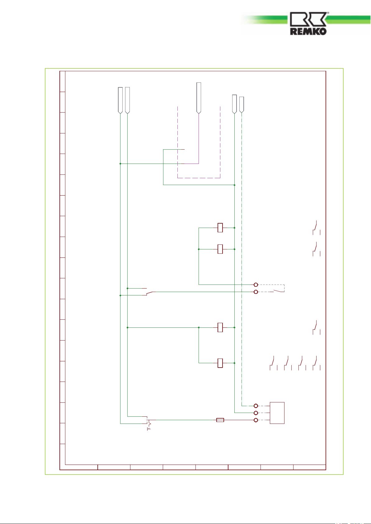
8.5 Circuit diagrams
L1
N
PE
T6,3A
11
12
14
1.S 1
A2 A1
K1C
11
14
12
/1.9C
11
14
12
K1C
/1.7E
4
X1
5
1 2
F1.
A2 A1
K2A
11
14
12
/3.8C
A2 A1
K2B
11
14
12
/4.14C
20
21
A2 A1
K1
21
24
22
/2.11C
31
34
32
/4.7C
41
44
42
/3.10C
11
14
12
/2.9C
N1.1/2.2F
L1.AUTO/2.2B
L1.HAND/2.2B
PE /2.2F
L1.R EL. PLA/2.2E
Auto Hand0
L N
L
N
PE
A
B
C
D
E
F
G
H
1 2 3 4 5 6 7 8 9 10 11 12 13 14 15 16 17 18 19
Function switch
SUPPLY
Flow monitor
or
jumper by
hot water meter
Power supply relays board
(Heat pump manager)
Circuit diagram 15.04.2011 page 1/8
Fig. 45: Circuit diagram electrical junction box EMF/EMT 1
45

weiss
WP
E1
E2
22
23
24
25
26
27
28
11
14
12
K10
/3.11E
6
X1
7
15
X1
16
17
18
X1
19
20
21
X1
22
23
24
X1
25
26
27
11
14
12
K7
/5.16E
N
L
PE
M1
N
L
PE
M2
Z
A
N
M3
Z
A
N
M4
A2 A1
K11
11
14
12
/4.5C
2.H4
21
24
22
K1
/1.5E
11
14
12
K1
/1.5E
L1.AUTO/1.17B
L1.AUTO/3.2B
N1.1/1.17F
N1.1/3.2F
K7/10_11/3.8D
L1.HAND/1.17B
L1.HAND/3.2B
PE /1.17F
PE /3.2F
L1.R E L.P LA/1.17E
L1.R E L.P LA/3.2A
E1 E 2
A2A1 A3 A4 A5
L L'
A
B
C
D
E
F
G
H
1 2 3 4 5 6 7 8 9 10 11 12 13 14 15 16 17 18 19
Circulation
pump HK 1
Circulation
pump HK 2
Mixer circuit
Switchingvalve
Hot-water usage
Hot-water
usage active
3-way mixer
Mixer HK2
Outputs relay board (Heat pump manager)
Inputs Relay board
(Heat pump manager)
Power
disable
Circuit diagram 15.04.2011 page 2/8
REMKO EMF / EMT
Fig. 46: Circuit diagram electrical junction box EMF/EMT 2
46

31
S
30
O
29
34
S
33
O
32
S
38
37
39
40
A2 A1
K9
11
14
12
/3.11C
11
14
12
K9
/3.14E
A2 A1
K10
11
14
12
/2.7C
11
14
12
K5A
/4.7E
8
X1
9
10
11
12
X1
13
14
28
X1
29
30
31
32
X1
33
34
35
X1
36
37
38
X1
39
40
Z
A
N
M5
11
14
12
K2A
/1.11E
A2 A1
K3
11
14
12
/6.12C
11
14
12
K5B
/4.8E
N
L
PE
M6
N
L
PE
M8
Z
A
N
M7
N
L
PE
M9
A2 A1
K4
11
14
12
/6.9C
41
44
42
K1
/1.5E
L1.AUTO/2.17B
L1.AUTO/4.2B
L1.HAND/2.17B
L1.HAND/4.2B
N1.1/2.17F
PE /2.17F
L1.R E L.P LA/2.17A
K7/10_11/2.7D
A10 A12
A9A6
A7
A
B
C
D
E
F
G
H
1 2 3 4 5 6 7 8 9 10 11 12 13 14 15 16 17 18 19
Outputs relay board (Heat pump manager)
enable2. heat source 4-way switching valve
2. heat source
Charging pump,
indoor module
Switching valve,
cooling
Circulation pump,
cooling
Circulation pump,
solaror circulation or
Solid-fuel combustion
vessel
Circuit diagram 15.04.2011 page 3/8
Fig. 47: Circuit diagram electrical junction box EMF/EMT 3
47

gelb
S
36
35
A2 A1
K5A
11
14
12
/3.6C
A2 A1
K5B
11
14
12
/3.4C
4.H2
11
14
12
K2B
/1.12E
1
X1
2
3
41
X1
42
43 11
14
12
K11
/2.8E
31
34
32
K1
/1.5E
L1.AUTO/3.17B
L1.AUTO/5.2B
N1.1/3.17F
N1.1/5.2F
L1.HAND/3.17B
L1.HAND/7.2D
E-S TAB/7.2E
N1.2/7.2F
A8
A
B
C
D
E
F
G
H
1 2 3 4 5 6 7 8 9 10 11 12 13 14 15 16 17 18 19
Power otput relay board (Heat pump manager)
Connections for optional module
electrical booster heater
Additional heat source
element active
External collector fault
Circuit diagram 15.04.2011 page 4/8
REMKO EMF / EMT
Fig. 48: Circuit diagram electrical junction box EMF/EMT 4
48

~230V IN
~230V Out
~15V IN
rotgrün
5.H1
CN11.1
CN11.3
CN71.1
CN71.3
CN72.1
CN72.3
S
CN23.5
CN23.6
S
CN23.3
CN23.4
1
2 3
4
TR 1
5.H3
A2 A1
K7
11
14
12
/2.6C
L1.AUTO/4.17B
N1.1/4.17F
A
B
C
D
E
F
G
H
1 2 3 4 5 6 7 8 9 10 11 12 13 14 15 16 17 18 19
Circuit diagram 15.04.2011 page 5/8
Power supplys COMM_KIT_PBA
FaultOperation
Fault
Operation
Fig. 49: Circuit diagram electrical junction box EMF/EMT 5
49

CN51.1
CN51.2
CN43.1
CN43.2
CN83.1
CN83.2
CN41.1
CN41.2
CN41.3
CN41.4
CN41.5
CN41.6
CN31.1
CN31.2
CN44.1
CN44.3
11
14
12
K3
/3.7E
R3 R 4 R 5
11
14
12
K4
/3.8E
KOMM_1/8.2A
MASS E /8.2B
0-10V/8.2C
KOMM_2/8.2A
A
B
C
D
E
F
G
H
1 2 3 4 5 6 7 8 9 10 11 12 13 14 15 16 17 18 19
Circuit diagram 15.04.2011 page 6/8
Heat/Cooling
Heater
pre-flow
Compressor
emergency stop
Compressor
enable
Fluid
coolant
Heater
return
Communications
Outdoor unit
Control signal
Outdoor unit
Sensor & control connections COMM_KIT_PBA
REMKO EMF / EMT
Fig. 50: Circuit diagram electrical junction box EMF/EMT 6
50

47n
1K
47n
1K
30 - 78°C
A2 A1
K8
13 14
21
3 4
5 6
/7.12C
21
3 4
5 6
K8
/7.6E
A2 A1
K6
13 14
/7.11C
21
3 4
5 6
/7.9C
13 14
K6
/7.4E
21
3 4
5 6
K6
/7.4E
C2
R2
C1
R1
1
X2
2
3
4
5
E-S TAB/4.17G
N1.2/4.17G
L1.HAND/4.17G
PE /3.17F
PE
N
L3
L2
L1
A
B
C
D
E
F
G
H
1 2 3 4 5 6 7 8 9 10 11 12 13 14 15 16 17 18 19
Additional heating
fixed 92°C
1. level 2. level
Circuit diagram 15.04.2011 page 7/8
Additional heating
Module electrical additional heater (optional)
SUPPLY
Fig. 51: Circuit diagram electrical junction box EMF/EMT 7
51

REMKO EMF / EMT
H
G
F
E
D
C
B
A
1 2 3 4 5 6 7 8 9 10 11 12 13 14 15 16 17 18 19
KOMM_2/6.17A
KOMM_1/6.17A
0-10V/6.17B
MASS E/6.17B
X4
1
2
3
4
5
Sensor ground
6
7
8
9
10
11
12
13
14
15
16
Circuit diagram 15.04.2011 page 8/8
Control panel
Heat pump manager
4
3
2
1
Return, heat pump
Flow rate transmitter
Solar collector/
Solid-fuel combustion
Reference sensor, lower
Reference sensor
hot water meters
Reference sensor
Solid-fuel combustion
Analogue remote control
with room sensor FBR-2
(only HK 1 - direct HK)
Inlet HK2 (mixing circuit)
Warm-water storage
T-collector (com. inlet)
Outdoor temperature
vessel
buffer storage
vessel
X3
ws
bl
F15
1 3
FB R-2
2
F5 F6 F 8 F 9F11F12F14F17 F 1
19
18
17
16
15
14
13
12
11
10
9
8
7
6
5
4
3
2
1
Sensor inputs Relay board (Heat pump manager)
CAN +
CAN -
CAN L
CAN H
eBus -
eBus +
F17
F15
F14F14
F13
F12
F11
F1
F2
F3
F5
F6
F8
F9
Fig. 52: Circuit diagram electrical junction box EMF/EMT 8
52

8.6 Auxiliary relays and contactor function
Auxiliary
relays
K1C Activation of the flow monitor ... in emergency
K2A Setting the heat pump demand to OFF
K2B Contactor terminal K8 shut-off (second
K3 Setting the heat pump demand (com-
K4
CN 51.2
K5A Actuation of the switching valve for the 2nd
K5B Makes the zero potential contact available
K6 Electric heating contact, level 1 (6 kW) ... in normal operation
Function Use ... Found in the circuit
heating mode (Manual
mode)
... in normal operation
with a flow fault
level electric heating, 3 kW) with flow fault
pressor). Compressor ON, if K3 is deactivated and contact on the control board is
closed.
Setting the cooling release. Cooling ON if
K4 has activated and contact on the control board is open.
heating source
for the demand of the 2nd heating source
(Automatic mode)
... in normal operation
(Automatic mode)
CN 83.1 und 83.2
... in normal operation
(Automatic mode)
CN 51.1
... in normal operation
(Automatic mode)
... in normal operation
(Automatic mode)
(Automatic mode) and
in emergency heating
mode (Manual mode)
diagram ...
Ä
on page 45
Ä
on page 45
Ä
on page 45
Ä
on page 47
Ä
on page 47
Ä
on page 47
Ä
on page 48
Ä
on page 51
K7 Release of a fault of the outdoor unit and
issue of the fault message "Heat pump
fault" in the display of the heat pump manager (contact opening input E2)
K8 Electric heating contact, level 2 (3 kW) ... in emergency
K9 Switching on of the charging pump in the
indoor module parallel to the output
cooling circulating pump/switching valve
K10 Enabling of the fault input E2 of the heat
pump manager ("Heat pump fault" contact
opening input E2) after the indoor unit
charging pump was switched on.
K11 External error message ... in normal operation
... in normal operation
(Automatic mode)
heating mode (Manual
mode)
... in cooling mode
(Automatic mode)
... in normal operation
(Automatic mode)
(Automatic mode)
Ä
on page 49
Ä
on page 51
Ä
on page 47
Ä
on page 47
Ä
on page 48
53

3
1
5
6
2
4
REMKO EMF / EMT
Fig. 53: Auxiliary relays
9 Commissioning
9.1
Fig. 54: Control panel
1. Mode switch
2. Green indicator light: outdoor module is acti-
3. Orange indicator light: operation 2nd heat
Position I: Normal operation
This switch turns on the system. The heat pump and a possible 2nd heat source (6 kW E-heater or boiler),
load- and weather-dependent, are turned on and off - as well as regulated - automatically.
Control panel
vated
source
4. Red indicator light: outdoor module failure
5. White indicator light: drinking water preparation
is activated
6. Heat pump manager (Control and display unit)
Position 0: OFF
Position II: Emergency-heat operation
This switch directly turns on all circulation pumps
and the 2nd heat source (9 kW E-heater or boiler),
bypassing the heat-pump manager. Use this position only if a serious malfunction of the heat pump
occurs (e.g.: a fault in the outdoor module or
in the heat-pump manager). This function might
also be helpful if heat is ever required and the outdoor module has not yet been installed or or
placed in service.
54

NOTICE!
Make sure that no weather-driven control
occurs during emergency-heat operation.
Therefore, limit the inlet temperature at the
controller for the electric booster heater or at
the external controller for the boiler to a maximum temperature matched to the boiler. (e.g.:
55 °C for floor heating-systems)!
NOTICE!
When the heat pump is switched off (position 0
on the function switch), the heating system is
switched off. There is no frost protection function..
9.2 Notes for commissioning
The Multitalent heat pump manager serves to
operate and control the entire plant. The heat
pump manager itself is operated by the control
unit. The control console is connected to the basic
device and is located behind the flap on the indoor
module.
Home
A
Fig. 56: Control panel in detail
The rotary knob (A) can be used to toggle between
the displayed menu points or to change the set
values.
Pressing the Home button (B) always returns you
to the standard display.
Each of the four function keys (C) stand for one of
the four rows on the display. Pressing an F button
serves to select a menu item or set value.
After a power failure etc., the previously programmed configuration can be accepted immediately by pressing the function button next to
"End". This also happens automatically after a
delay of 10 minutes.
B
C
C
B
A
Fig. 55: Control panel
The heat pump manager is controlled by means of
the following buttons.
n System 1 is pre-installed at the factory. After a
reset of the heat-pump manager, the parameters for System 1 are loaded.
n An intensive visual inspection is to be carried
out before the actual commissioning.
n Switch on the electrical supply.
n The following screen appears on the Multitalent
display:
End
Installation
Fig. 57: Display screen "Installation"
OK
55

REMKO EMF / EMT
n Check which system schematic is used (see
the hydraulic schematic in the heat-pump manager handbook).
n If the System 1 schematic is applicable, you
need only press the F-button next to End.
Should a different system schematic be
selected, press the F-button next to OK to
begin installation.
n The configuration in the installation level for the
selected hydraulics has to be completely programmed with the parameters that go with
it (see the hydraulic schematic in the heatpump manager handbook).
n The system has to be matched to the custom-
er's personal values (e.g. inlet temperature).
n The brief instructions supplied give an over-
view of how to set the most important values.
n After configuration, the system is to be run-in
and the measured values are to be recorded in
the commissioning report.
NOTICE!
The commissioning and programming of the
heat-pump manager may be carried out only
by an installer authorized by REMKO.
Level 0
Fr 23 Apr 10 16:05
T-external 19.0 °C
T-collector 36.2 °C
Heating
Home
Level 1
Main menu
End01
Terminal
Controller
Level 2
Controller
End01
Display
User
Time programme
Level 3
Display
End01
Plant
Hot water
Heating circuit 1
Please review the heat-pump manager manual
for important details about successful commissioning.
During commissioning, only a typical heatmanager pre-set is made. Individual settings
must be optimized for construction materials
and the practices of various users. Especially
during the first heating period.
9.3 Heat pump manager MultiTalent Plus (heat flow
meters)
The Multitalent heat pump manager PLUS is
equipped with the following displays relevant for
the heat flow meters:
Level 4
Plant
End07
Flow volume 28 l/min
Current output 8070 W
Output day 30.2 kWh
Level 4 (continued)
Plant
End07
Output day 30.2 kWh
Output total 99 kWh
Error 00
Fig. 58: Display level
Specialist level
The heat pump menu is found in the specialist
level. The parameters for the heat flow meters are
configured here.
Display level
The displays relevant to the heat flow meters are
called up with the following steps on the heat pump
manager.
56
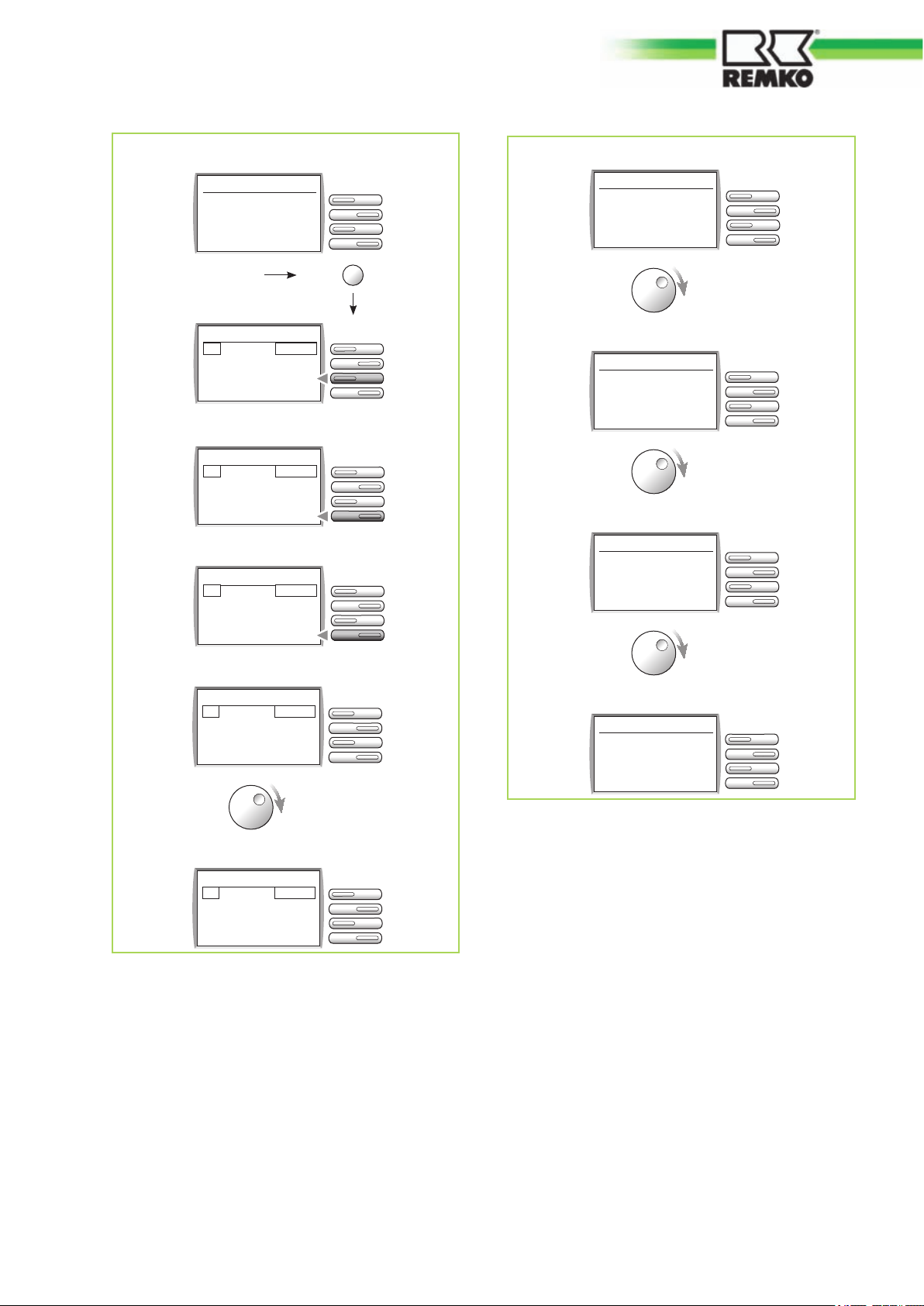
Level 0
Fr 23 Apr 10 16:05
T-external 19.0 °C
T-collector 36.2 °C
Heating
Level 1
Main menu
End01
Terminal
Controller
Level 2
Controller
End04
Time-Date
Service
Specialist
Level 3
Specialist
End02
Heating appliance
Cascade
Heat pump
Level 0
Fr 23 Apr 10 16:05
T-external 19.0 °C
T-collector 36.2 °C
Heating
Home
Level 0
Fr 23 Apr 10 16:05
Current output 8070 W
T-collector 36.2 °C
Heating
Level 0
Fr 23 Apr 10 16:05
Output day 30.2 kWh
T-collector 36.2 °C
Heating
Level 4 (continued)
Heat pump
End05
E1 function 02
E2 function 03
E15 function 09
Level 4
Heat pump
End12
Impulse rate 1
Impulse unit l/Imp
Min FlowVol 12.0 l/min
Fig. 59: Specialist level
Including in display of favourites
As many as 10 display values can be copied to
level 0. The system operator can quickly access
these "favourites" for control purposes without
involving himself with the heat pump manager. The
possible heat flow meter displays included in the
favourite menu are shown in the following section.
Level 0
Fr 23 Apr 10 16:05
Output total 99 kWh
T-collector 36.2 °C
Heating
Fig. 60: Including in display of favourites
57

REMKO EMF / EMT
10 Care and maintenance
Regular care and maintenance serves to ensure
trouble-free operation and long service-life of the
heat pump system.
Care
n The indoor and outdoor modules must be kept
free of soiling, vegetation and other deposits.
n The device is to be cleaned with a damp cloth.
In doing so, it is to be ensured that no caustic,
abrasive or solvent-based cleaning products
are used. Use of powerful water jets is to be
avoided.
n The fins on the outdoor module are to be
cleaned at least once a year.
Maintenance
n To perform the statutory seal test, it is neces-
sary to arrange an annual maintenance contract with an appropriate specialist firm.
NOTICE!
As the refrigerant capacity exceeds 3 kg, an
annual seal inspection must be made of the
refrigerant circuit by a firm specializing in this
field. A heating system should always be serviced annually. Therefore, we recommend
arranging for a service contract that includes
the seal inspection.
58

11 Troubleshooting and customer service
The unit has been manufactured using state-of-the-art production methods and tested several times to
ensure its correct function. However, in the event that malfunctions should occur, the device should be
checked against the following list. Please inform your dealer if the unit is still not working correctly after all of
the functional checks have been performed.
Fault Possible causes Remedial measures
The heat pump does
not start or switches
itself off
Heat circuit pump fails
to switch off
Heat circuit pumps fail
to switch on
Power outage, under-voltage Check the voltage and, if necessary,
wait for it to come back on
Defective mains fuse Master switch off Exchange mains fuse, master switch on
Damaged mains cable Repair by specialist firm
Power company off-period Wait until the power-company off-
period is over and the heat pump starts
up as required
Operational temperature limits too low
or too high
Set-point temperature exceeded Incorrect mode
Disconnect the outdoor module, then
Incorrect pump switching Arrange to have pump switching
Incorrect mode set Check mode
Control PCB fuse in indoor module
switching cabinet faulty
Observe temperature ranges
The set-point temperature has to be
higher than the heat-source temperature, check mode
establish the correct clamp order using
the connection plan Re-establish
voltage to the outdoor module. Also
make sure that the protective earth is
connected correctly.
checked in "heating circuit" expert level
Exchange the fuse on the left side of
the control PCB
Incorrect heating program set Check heating program We recom-
mend the operating mode "heat" in the
cold heating season
Temperature overlapping, e.g. external
temperature greater than room temperature
Troubleshooting
Troubleshooting A corresponding error code
appears on the heat pump manager display in the
event of a fault in the heating system. The meanings of the displayed error codes can be taken
from the table on the next page. The system
should be restarted after a brief shut-down after
the fault has been rectified (turn the mode switch
off then on again). Subsequently the heat-pump
manager will re-start, automatically reconfigure and
continue to operate with the set values.
59
Heat pump manager error codes
The error codes listed in the table can be called up
in the display of the heat pump manager. See Controller ---> Displays ---> System ---> Errors. If an
error with a corresponding code is present, an
error scan can be performed by pressing the
assigned function key. After a short period of time
the 10 most recent faults, including the date and
time, are listed with the exception of error codes 54
and 55. They are treated as recurring messages
and are not listed in the error scan.
Observe temperature ranges

REMKO EMF / EMT
Error codes Fault description / note
E 51 Notice that annual maintenance is needed
E 54 Message: “Heat pump fault”.The flow monitor has tripped. A flow problem has occurred.
Possible causes are air in the system, a clogged dirt trap or a defect of the charging pump
in the indoor module. If the red indicator lamp illuminates, there is a problem in the outdoor
module which can only be remedied through customer service.
E 55 “Power company shut-off” message. Information that the power company has begun an
off-period. The heating pump is switched off. The second heating appliance is switched on
as necessary. The electrical heating must be locked on-site using a relay switch.
E 69 Failure or short in supply sensor HK2 (mixing circuit). Sensor F5
E 70 Failure or short inlet pipe WP Multi-purpose sensor 1. Sensor F11
E 71 Failure or short in lower buffer sensor. Sensor F12
E 75 Failure or short, external sensor. Sensor F9
E 76 Failure or short, domestic warm water sensor. Sensor F6
E 78 Failure or short, collector sensor. Sensor F8
E 80 Failure or short, FBR2 analogue remote control (for HK 1)
E 81 EEPROM error. The valid value has been replaced by the default value. Check parameter
values!
E 90 Address 0 and 1 on bus. Bus codes 0 and 1 may not be used simultaneously.
E 91 Bus code assigned. The set bus code is already being used by another device.
E 135 Failure or short, lower WW buffer sensor reference sensor solar) . Sensor F12
E 137 Failure or short in collector sensor 1, sensor F14 (PT 1000) or sensor solid-fuel combustion
vessel
E 140 Failure or short in return line (cooling-mode control sensor) Sensor F17
E 200 - E 207 Error communication heating appliance 1 to WE 7
E 220 - E 253 Error communication digital remote control BM 0 to BM 15
E 240 Error communication manager
E 241 Error communication (individual) heating appliances
E 242 Error communication mixer
E 243 Error communication solar
60

Outdoor unit error display
1
Fig. 61: Display on outdoor module
1. Display screen
Display code Meaning
E177 Emergency mode
E202 Abnormal communication between the HYDRO-unit and the outdoor unit
E203 Abnormal communication between MAIN MICOM external and INVERTER
MICOM
E221 Error in the external temperature sensor (short / open)
E237 Error inductor temperature sensor (short / open)
E251 Error outlet temperature sensor (kurz/offen)
E401 Coil of the unit hydro-frozen at cooling mode
E404 Coil of the HYDRO-unit in heating mode overloaded
E416 Outdoor temperature overheat
E440 Outdoor temperature of about 30 °C in heating mode
E441 Outdoor temperature of below 5°C in cooling mode
E458 Error 1. fan
E475 Error 2. fan (only 14 kW model)
E471 OTP-Error
E460 Communication error voltage
E461 Error Komp-Start
E464 Over current IPM (O.C)
E465 Compressor overloaded
E466 Error DC-Link over-/undervoltage
E467 Error compressor rotation
E468 Current sensor error
E469 Error DC-Link voltage sensor
E556 Mismatch capacity between HYDRO and outdoor unit
See
Ä
‘Heat pump manager error codes ’ on page 59 above.
61

15
14
6
13
16
5
1
2
18
7
4
10
11
12
8
E-
3
9
19
17
REMKO EMF / EMT
12 Exploded view and spare parts
12.1 Exploded view and spare parts list outdoor module
Fig. 62: Exploded view outdoor module EMF 100 / EMT 100
62

We reserve the right to modify the dimensions and constructional design as part of the ongoing technicaldevelopment process.
Spare parts list outdoor module EMF / EMT 100
No. Designation EMF 100 EMT 100
From series: 739B5001... 1064B5001...
EDP-Number EDP-Number
1 Compressor 1120280 1120280
2 Laminated heat-exchanger 1120281 1120281
3 Four-way switching valve 1120282 1120282
4 Shut-off valves 1120283 1120283
5 Fan blade 1120284 1120284
6 Cover panel 1120285 1120285
7 Side panel, left 1120286 1120286
8 Front panel 1120287 1120287
9 Grille, front 1120288 1120288
10 Side panel, right 1120289 1120289
11 Cover, right 1120290 1120290
12 Grille, rear 1120291 1120291
13 Fan motor 1120292 1120292
14 Sensor evaporator / compressor sensor-set 1120293 1120293
15 Sensor hot gas / Sensor outdoor temperature-set 1120294 1120294
16 Transformer 1120296 1120296
17 Elektronic expansion valve 1120297 1120297
18 Main board 1120298 1120298
19 Display 1120299 1120299
When ordering spare parts, please state the computerised part no., device number and device type (see
name plate)!
63

REMKO EMF / EMT
12.2 Exploded view and spare parts list indoor module
Exploded view indoor module EMF 100
16
20
21
17
14
22
19
2
3
18
A
1
1
1
7
13
15
4
23
5
10
14
9
32
24 252627
Fig. 63: Exploded view indoor module EMF 100
A
Accessory Set (
We reserve the right to modify the dimensions and constructional design as part of the ongoing technicaldevelopment process.
Ä
‘Parts and fittings, set’ on page 68)
28
29
30
31
33
6
8
12
64

Spare parts list indoor module EMF 100
No. Designation EMF 100
From series: 738B5001 EDP-number
1 Housing 1120009
2 Front panel 1120006
3 Door with hinge 1120005
4 Housing for controls 1120004
5 Controls, complete 1120243
6 Control module 1120029
6 Control module (in the form of a hot water meter) 1120190
7 Heat exchanger (condenser) with insulation 1120151
8 Pipe assembly, complete with insulation 1120242
9 Circulation pump Grundfos 1120241
10 Flow monitor 1120154
10 Flow meter (in the form of a hot water meter) 1120193
12 Fill/drain valve 1120028
13 Bleeder 1/4“ 1120059
15 Brass plug 2“ 1120155
23 Relay board, WP-Manager (Merlin I/O-Platine) 1120030
23 Relay board, WP-Manager (in the form of a hot water meter) 1120194
24 Control board 252001
25 Mounting 1120300
26 Sensor terminal block 1120244
27 White indicator light 1120027
28 Red indicator light 1105363
29 Orange indicator light 1105512
30 Green indicator light 1105514
31 Mode switch 1120157
32 Relays (Finder) 1120095
33 Retrofitting kit electric heating 1120147
Spare parts (not illustrated)
Liquid sensor, cooling circuit / return / inlet-set 1120306
Socket for service module 1120032
Electric booster-heating, 2", max. 9 kW 1120160
When ordering spare parts, please state the computerised part no., device number and device type (see
identification plate)!
65

REMKO EMF / EMT
Exploded view indoor module EMT 100
24
23
22
17
12
21
25
26
32
14
23
9
23
8
24 252627
27
28
29
A
30
10
31
33
11
19
16
13
7
15
2
3
4
7
5
Fig. 64: Exploded view indoor module EMT 100
A
Accessory Set (
We reserve the right to modify the dimensions and constructional design as part of the ongoing technicaldevelopment process.
Ä
‘Parts and fittings, set’ on page 68)
66

Spare parts list indoor module EMT 100
No. Designation EMT 100
From series: 1065B5001 EDP-number
1 Housing 1120301
2 Front panel, upper 1120302
3 Front panel, centre 1120303
4 Front panel, lower 1120304
5 Base-feet, set 1120245
6 Buffer storage with insulation 1120246
7 Fill/drain valve 1120028
8 Housing for controls 1120247
9 Controls, complete 1120243
10 Control module 1120029
10 Control module (in the form of a hot water meter) 1120190
11 Circulation pump 1120241
12 Heat exchanger with insulation 1120151
13 Pipe assembly, complete with insulation 1120305
14 Immersion sensor 260090
15 3-way switching valve, hydraulic, lower part 260070
16 Flow monitor 1120154
16 Flow meter (in the form of a hot water meter) 1120193
17 Electric booster-heating, 2", max. 9 kW 1120160
19 Bleeder 1/4“ 1120059
28 Relay board, WP-Manager (Merlin I/O-Platine) 1120030
28 Relay board, WP-Manager (in the form of a hot water meter) 1120194
29 Control board 252001
30 Mounting 1120007
31 Sensor terminal block 1120244
32 Red indicator light 1105363
33 Green indicator light 1105514
34 White indicator light 1120027
35 Orange indicator light 1105512
36 Mode switch 1120157
37 Relays (Finder) 1120095
38 Retrofitting kit electric heating 1120148
When ordering spare parts, please state the computerised part no., device number and device type (see
identification plate)!
67

REMKO EMF / EMT
No. Designation EMT 100
Spare parts (not illustrated)
Actuator for 3-way switching valve 1120054
Valve-core for 3-way switching valve 1120001
Liquid sensor, cooling circuit / return / inlet-set 1120306
Quadrelays ( normally open) 230V 1120307
Socket for service module 1120032
When ordering spare parts, please state the computerised part no., device number and device type (see
identification plate)!Bestandteile Zubehör-Set
Parts and fittings, set
No. for
EMF 100
EDP-number
16 21 Fittings set, complete 260005
14 14 Immersion sensor 260090
17 22 Dirt trap 1120013
18 23 Ball valve 1“, red 1120011
19 24 Ball valve 1“, blue 1120012
20 25 Contact sensor 260100
21 26 Safety assembly 1120010
22 27 External sensor 1120014
When ordering spare parts, please state the computerised part no., device number and device type (see
identification plate)!Bestandteile Zubehör-Set
No. for
EMT 100
Designation
EMF 100
EMT 100
68

13 Temporary shut-down
The system may not be switched off at the mains
power supply even if the heating system is not
used for heating purposes over an extended period
(e.g. holidays)!
n The system is to be switched to "Stand-by"
mode during temporary shut-down periods.
n Heating phases can be programmed for the
duration of the period of absence.
n The previous operating mode has to be
switched back on when the shut-down phase
is over.
n Instructions for changing the mode appear in
the corresponding chapter of the heat-pump
manager's manual.
NOTICE!
In "Standby" , the heat pump is in standby
mode. Of the entire system, only the frost-protection function s activated.
15 Environmental protec-
tion and recycling
Disposal of packaging
All products are packed for transport in environmentally friendly materials. Make a valuable contribution to reducing waste and sustaining raw materials. Only dispose of packaging at approved
collection points.
Disposal of equipment and components
Only recyclable materials are used in the manufacture of the devices and components. Help protect
the environment by ensuring that the devices or
components (for example batteries) are not disposed in household waste, but only in accordance
with local regulations and in an environmentally
safe manner, e.g. using certified firms and recycling specialists or at collection points.
14 Transport and pack-
aging
The devices are supplied in a sturdy shipping container. Please check the equipment immediately
upon delivery and note any damage or missing
parts on the delivery and inform the shipper and
your contractual partner. For later complaints can
not be guaranteed.
WARNING!
Plastic films and bags etc. are dangerous toys
for children.
Why:
- Leave packaging material are not around.
- Packaging material may not be accessible to
children!
69

REMKO EMF / EMT
16 EC- Declaration of Con-
formity
We do hereby declare that the devices named
below, produced and sold by us, satisfy the relevant basic requirements of the EC guidelines, the
EC safety standards and other product-specific EC
standards.
Name of Manufacturer and name of CE-representative:
REMKO GmbH & Co. KG
Air conditioning and heating technology
Im Seelenkamp 12
D - 32791 Lage
Equipment (machinery) - Implementation:
Inverter heat pump with refrigerant R410A
Series / Designation:
EMF 100, EMT 100
Series / Class Number:
739B5001, 1064B5001, 738B5001 und
1065B5001
Applicable regulations (EC-Directive)
Applicable Standards:
(Harmonized EN)
EN 378-1:2008 - Cooling-devices and heat-pump
safety-and environment-related requirements
EN 378-2:2008, EN 378-3:2008, EN 378-4:2008
EN 50366:2003 - Electrical devices for household
use and similar purposes - electromagnetic fields
EN 55014-1:2010-02 - Electromagnetic compatibility - requirements for household appliances,
electric tools and similar electrical devices (earlier:
VDE 0875)
EN 55014-2:1997 / A1:2001 (Category IV) - Safety
of electrical devices for household use and similar
purposes (earlier: VDE 0700)
EN 60335-1: 2002 / A11: 2004 / A1: 2004
EN 60335-2-40: 2003 / A11: 2004 / A12: 2005 /
A1: 2006
EN 61000-3-2:2006 - Electromagnetic compatibility
(EMV, earlier: VDE 0838)
EN 61000-3-3:1995 / A1:2001 / A2:2005
Lage, 25. February 2010
REMKO GmbH & Co. KG
........................................
Signature Product Manager
MA - RL 2006/42/EC - Machine directive
NS - RL 2006/95/EC - Low-voltage directive
EMV – RL 2004/108/EC - Electro magnetic fields
EnVKV - RL 92/75/EC - Energy Labelling directive
EG 97/23/EG - Pressure Equipment Directive
70

17 General terms
Annual power input factor
The annual power input factor indicates the power
input (e.g. electrical energy) required in order to
achieve a certain benefit (e.g. heating energy). The
annual power input factor includes the energy
required for auxiliary drives. Calculation of the
annual power input factor is undertaken according
to VDI – Directive 4650.
Bivalent mode
The heat pump provides the entire heating energy
down to a predetermined outdoor temperature
(e.g. 0°C). If the temperature drops below this
value, the heat pump switches off and the secondary heating appliance takes over the heating, e.g.
a heating boiler.
Coefficient of performance
The current ratio of thermal output produced by the
heat pump to the consumed electrical power is
referred to as the coefficient of performance, as
measured under standardised boundary conditions
according to EN 255 / EN 14511. A coefficient of
performance of 4 means that a usable thermal
output amounting to 4-times the electrical power
consumption is available.
Energy supply company switching
Certain energy supply companies offer special tariffs for the operation of heat pumps.
Evaporator
Heat exchanger on a refrigerant plant which uses
the evaporation of a working medium in order to
extract heat from its environment at low temperatures (e.g. the outdoor air).
Expansion valve
Heat pump component for lowering the condensing
pressure on the vapour tension. In addition, the
expansion valve regulates the quantity of injected
refrigerant in relation to the evaporator load.
Heat carrier
Liquid or gas medium (e.g. water, brine or air), in
which heat is transported.
Heat pump system
A heat pump system consists of a heat pump and
a heat source system. For brine and water/water
heat pumps, the heat source system must be
made available separately.
Compressor (condenser)
Unit designed for the mechanical conveyance and
compression of gasses. Compression serves to
significantly increase the pressure and temperature of the medium.
Condenser
Heat exchanger on a refrigerant plant which liquefies a working medium in order to transmit heat to
its environment (e.g. the heating system).
Defrost
At outdoor temperatures below 5°C it is possible
that ice may form on the evaporators of air/water
heat pumps. The removal of this ice is referred to
as defrosting and is undertaken by supplying heat,
either regularly or as requirements dictate. Air/
water heat pumps with circuit reversal are distinguished by their requirements-based, quick and
energy-efficient defrosting system.
Heat requirement assessment
A precise dimensioning of the system must be carried out for heat pump systems in order to maximise efficiency. Calculation of the heat requirement is undertaken according to national
standards. However, approximate requirements
can be determined based on the W/m² tables multiplied by living space to be heated. The result of
this is the overall heat requirement, which includes
the transmission heat requirement and the infiltration heat loss.
Heat source
Medium from which the heat pump derives heat, in
other words, soil, air and water.
Heating output
Flow of heat emitted from the liquefier to the environment. The heating output is the sum of the electrical power consumed by the condenser and the
heat flux obtained from the environment.
71

REMKO EMF / EMT
Inverter
Power regulator which serves to match the speed
of the compressor motor and the speed of the
evaporator fans to the heating requirement.
Limit temperature / bivalence point
Outdoor temperature where the secondary heating
appliance cuts in under bivalent operation.
Monovalent mode
In this mode, the heat pump is the sole heating
appliance in the building all year round. Monovalent mode is primarily used in combination with
brine/water and water/water heat pumps.
Noise
Noise is transmitted in media such as air or water.
Essentially there are two types of noise, airborne
sound and solid-borne sound. Airborne sound is
transmitted entirely via the air. Solid-borne sound
is transmitted in solid materials or liquids and is
only partially radiated as airborne sound. The
audible range of sound lies between 20 and
20,000 Hz.
Refrigerant
The working medium used in a refrigerant plant,
e.g. heat pump, is referred to as the refrigerant.
The refrigerant is a liquid which is used for thermal
transfer in a refrigeration plant and which is able to
absorb heat by changing its state at low temperatures and low pressures. A further change of state
at higher temperatures and higher pressure serves
to dissipate this heat.
Seal inspection
System operators are obliged to ensure the prevention of refrigerant leakage in accordance with
the directive on substances that deplete the ozone
layer (EC 2037/2000) and the Regulation on Certain Fluorinated Greenhouse Gases (EC
842/2006). In addition, a minimum of one annual
service and inspection must be carried out, as well
as a sealing test for refrigerating plants with a
refrigerant filling weight over 3 kg.
Seasonal performance factor
The seasonal performance factor relates to the
ratio of heat content delivered by the heat pump
system to the supplied electrical energy in one
year. It may not be compared to the performance
number. The seasonal performance factor
expresses the reciprocal of the annual power input
factor.
Single energy-source mode
The heat pump covers a large proportion of the
required thermal output. On a few days per year an
electrical heating coil supplements the heat pump
under extremely low outdoor temperatures. Dimensioning of the heat pump for air/water heat pumps
is generally based on a limit temperature (also
known as balance point) of approx. -5 °C.
Sound pressure level
The sound pressure level is a comparable characteristic quantity for the radiated acoustic output of a
machine, for example, a heat pump. The noise
emission level at certain distances and acoustic
environments can be measured. The standard is
based on a sound pressure level given as a nominal noise level.
Refrigerating capacity
Heat flux extracted from the environment by the
evaporator (air, water or soil).
Regulations and guidelines
The erection, installation and commissioning of
heat pumps has to be undertaken by qualified specialist engineers. In doing so, various standards
and directives are to be observed.
Split AC unit
Design where one part of the device is positioned
outdoors and the other inside the building. Both
units are connected to each other by a refrigerant
pipe.
Storage tank
The installation of a hot-water storage tank is generally recommended in order to extend the running
time of the heat pump under low heat requirements. A storage tank is required for air/water heat
pumps in order to bridge off-periods.
72

Support
The German Reconstruction Loan Corporation
supports ecologically-sound construction and modernisation of domestic buildings for private individuals. This includes heat pumps which can be supported in the form of loans. The German Federal
Office of Economics and Export Control (BAFA)
subsidises the installation of effective heat pumps
(please refer to: www.kfw.de und www.bafa.de).
73

REMKO EMF / EMT
18 Index
A
Adding refrigerant.............................................. 37
C
Charging pump, motor protection...................... 12
Charging pump, pump-characteristic curves..... 12
Coefficient of performance................................... 9
Condensate draining and ensured discharge.... 30
Connection diagram........................................... 44
Contact sensor................................................... 40
COP..................................................................... 9
D
Disposal of equipment....................................... 69
E
Electrical connection
Indoor module............................................... 38
Outdoor module............................................ 39
Environmental protection................................... 69
External sensor.................................................. 40
G
Greenhouse gas according to Kyoto protocol...... 9
I
Installation
Indoor module............................................... 27
Outdoor module............................................ 28
Intended use........................................................ 6
L
Leak testing........................................................ 35
M
Minimum distances for the outdoor modules..... 29
O
Overall sound pressure levels............................ 14
P
Pipe-outlet spacing............................................ 10
Pipe-socket arrangement................................... 10
Pumping down to vacuum.................................. 35
S
Safety
Dangers of failure to observe the safety
notes............................................................... 5
General........................................................... 5
Identification of notes...................................... 5
Notes for inspection........................................ 6
Notes for installation....................................... 6
Notes for maintenance.................................... 6
Personnel qualifications.................................. 5
Safety-conscious working............................... 6
Safety notes for the operator.......................... 6
Unauthorised modification ............................. 6
Unauthorised replacement part manufacture
Setting up
Indoor module............................................... 27
Sound intensity.................................................. 14
Sound power level............................................. 13
Sound pressure level......................................... 13
Spare parts order......................................... 63, 65
T
Temperature sensors......................................... 40
Terminal configuration....................................... 44
Troubleshooting................................................. 59
W
Warranty.............................................................. 7
.. 6
74


REMKO INTERNATIONAL
… and also right in your neighbourhood!
Make use of our experience and advice
REMKO GmbH & Co. KG
Air conditioning and heating technology
Im Seelenkamp 12 D-32791 Lage
Postfach 1827 D-32777 Lage
Telephone +49 5232 6 06-0
Telefax +49 5232 6 06-260
E-mail info@remko.de
Website www.remko.de
Consulting
Thanks to intensive training,
our consultants are always
completely up-to-date in terms
of technical knowledge. This has
given us the reputation of being
more than just an excellent,
reliable supplier:
REMKO, a partner
helping you find solutions to
your problems.
Distribution
REMKO offers not just a well
established sales network both
nationally and internationally, but
also has exceptionally highlyqualified sales specialists.
-
REMKO field staff are more than
just sales representatives: above
all, they must act as advisers to
our customers in air conditioning
and heating technology.
SFlbCustomer Service
Our equipment operates
precisely and reliably. However,
in the event of a fault, REMKO
customer service is quickly at
the scene. Our comprehensive
network of experienced dealers
always guarantees quick and
reliable service.
We reserve the right to make technical changes, and provide no guarantee as to the accuracy of this data!
 Loading...