


Quinta Pro
The NEW Remeha
QUINTA PRO
Selection, Design and Installation
of Flue and Fluecade Systems
REMEHA QUINTA PRO | SELECTION, DESIGN AND INSTALLATION OF FLUE SYSTEMS
HIGH EFFICIENCY
108.9% NCV
PREMIX BURNER
CLEAN COMBUSTION
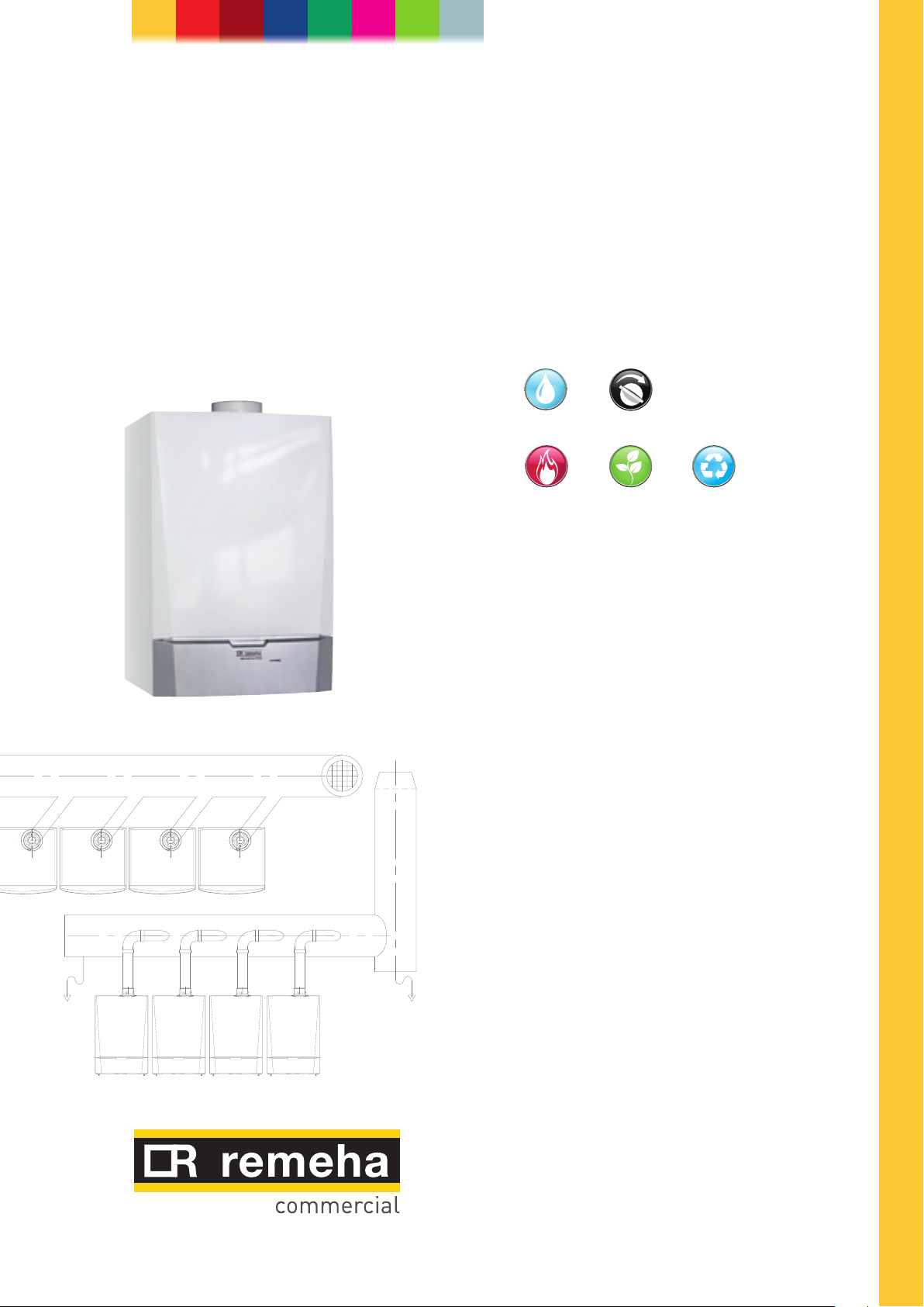
High efficiency wall hung condensing boiler
with ultra low NOx emission
QUINTA PRO RANGE OUTPUTS
QP30: 8.0 - 31.4 kW
QP45: 8.0 - 43.0 kW
QP65: 12.0 - 65.0 kW
QP90: 14.1 - 89.5 kW
QP115: 16.6 - 114.0 kW
FULLY MODULATING
BOILER CONTROL
ULTRA LOW NOx
BREEAM EXCELLENT
RECYCLABLE
MATERIALS

Quinta Pro Series flue options
The Quinta Pro series of boilers have fan assisted flues and are supplied as
standard with a ‘concentric’ flue outlet/air inlet which is used for room sealed
operation or for open flue (room ventilated) applications. An optional twin pipe
fitting is available for the room sealed ‘CLV’ system.
The concentric system can be supplied for individual boilers for horizontal or
vertical installation. Because of the excess fan capacity of the boiler, most flue
lengths can be accommodated (depending on boiler model and actual route taken),
which enables the installer to position the boiler almost anywhere in the building.
Open flue or room ventilated systems can be installed as individual or combined
flues and should discharge vertically with the flue terminating in a optional tapered
cone complete with bird guard.
Care should be taken when siting the actual discharge point as a vapour plume will
be visible when the boiler is operating (maximum flue gas exit temperature will be
less than 75°C) and it is possible for water to drip to the ground from the terminal
on horizontal installations, which could turn to ice in freezing conditions.
Recommendations
Refer to latest relevant British Standards
(Ref BS 5440 – 2: Specification for installation and maintenance of ventilation for
gas appliances not exceeding 70kW) (1st, 2nd and 3rd family gases)
(Ref BS 5440 – 1: Specification for installation of gas appliances to chimneys and for
maintenance of chimneys not exceeding 70kW) (1st, 2nd and 3rd family gases)
(Ref BS 6644: Specification for installation of gas-fired hot water boilers of rated
inputs between 70kW to 1.8 MW)(net)(2nd and 3rd family gases)
(Ref IGE/UP/10) Installation of flued gas appliences in industrial and commercial
premises.
It is the responsibility of the installer to install the flue and Flucade to comply with
the current regulations and standards.
IMPORTANT NOTE: All flue terminals and CLV kits are now supplied with a
condensate drain/adaptor. We would advise the fitting of this component if
installations are over 2 metres in length both vertically and horizontally and also if
the flue consists of dissimilar materials. Installations taken directly from the top of
the boiler horizontally through an outside wall do not require the condensate drain.
On flue components supplied by others, ensure in line condensate drains are fitted
in the correct positions.
Further details regarding flue with dissimilar metals can be found in
BS6644 – 2011 Section 6.10.4
Flue components are constructed from a white painted metal outer and plastic inner.
Flue terminals are painted as detailed in the terminal diagrams.
Plume kit external components are aluminium or plastic and are painted black.
All flue components are CE approved.
2
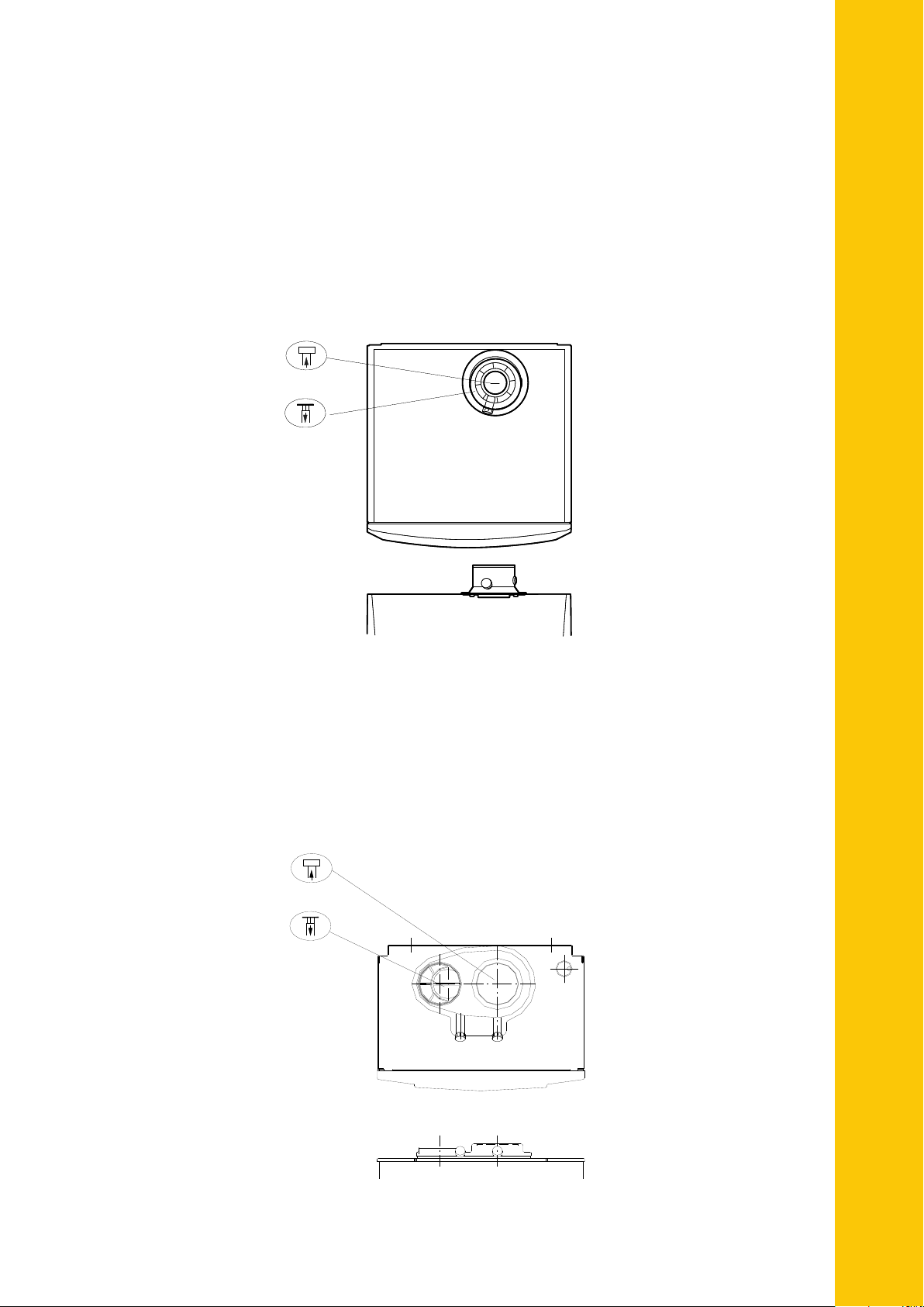
FLUE GAS
FLUE GAS
AIR IN
REMEHA QUINTA PRO | SELECTION, DESIGN AND INSTALLATION OF FLUE SYSTEMS
Quinta Pro Series Flue outlet / Air inlet details
The Quinta Pro Series boilers are supplied as standard with a Concentric Flue
outlet / Air inlet connection which can be used for:
1. Room sealed operation using the concentric flue system (Flue within air duct)
2. Conventional/Open flue operation using single skin flue system connected to the
inner concentric connection with the air supply taken from the boiler house via
the outer concentric connection.
AIR IN
This shows the optional Twin pipe Flue outlet / Air inlet connection and is used for
Room sealed operation using the CLV flue system (air inlet and flue gas discharge
from two pressure zones).
Using single skin, water and gas tight flue system with single skin air tight
air inlet system.
FLUE GAS
AIR IN
3
240mm
Sq.
4 x 5mm
Holes
204 Sq
Centre line of
Terminal 180mm
Clearance hole for
Terminal through
wall 130mm
Note:140mm diameter recess
15mm deep required from the
face of the i nside wall face to
allow clearance for the bend
Cut Terminal on site
to suit wall thickness
Max 1000mm
Min 150mm
Wall closure plate should be fitted
to terminal before passing
through hole in wall to ensure
correct positioning
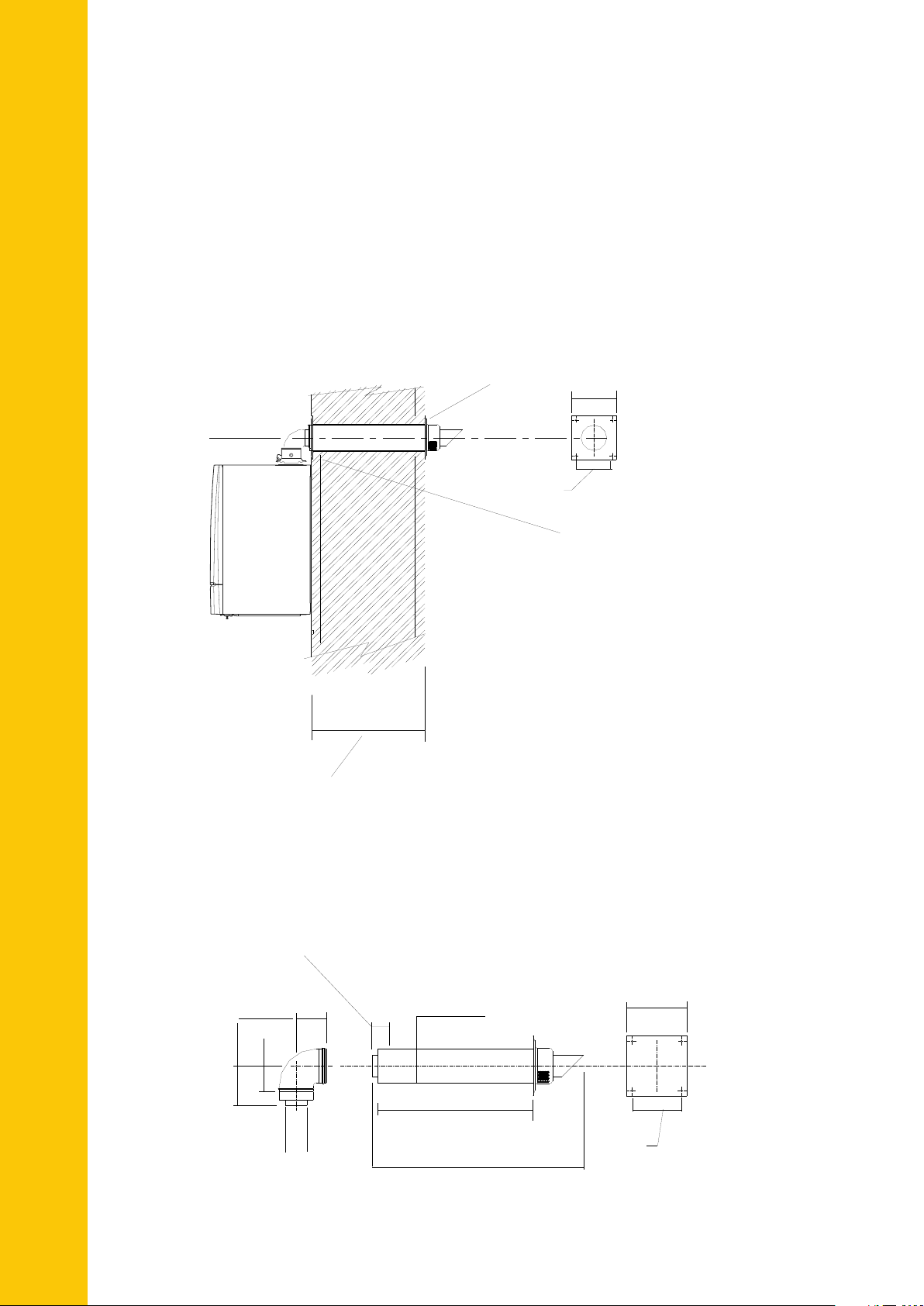
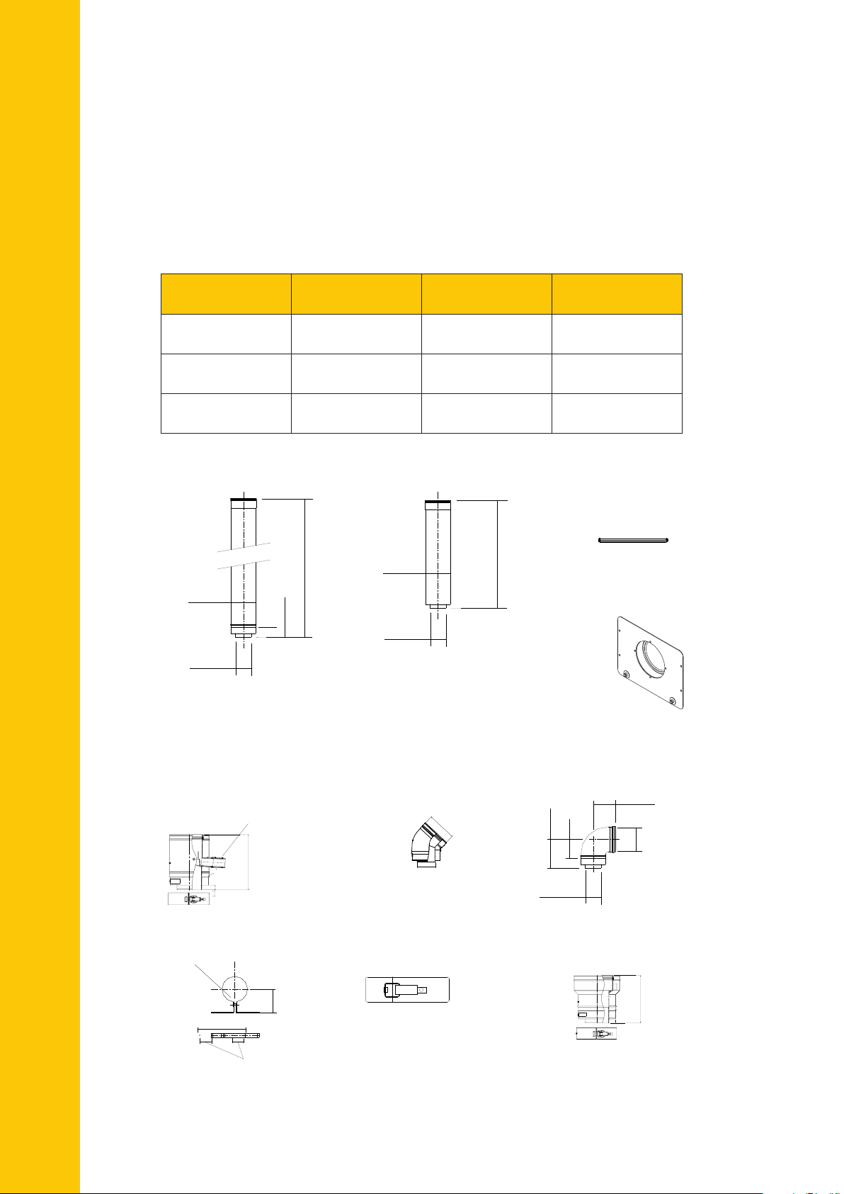
Quinta Pro 30 and 45 – Room Sealed, 80/125mm
Horizontal Concentric Flue Kit Option QP01
(For use when the boiler/s are mounted on and flued through a rear outside wall.)
Typical single boiler installation – can also be used for multiple boilers but each
must have its own flue system at a minimum of 530mm centres and never installed
immediately above another. For two boilers only it is also possible to install the
external terminal wall plates touching each other.
Wall closure plate should be fitted
to terminal before passing
through hole in wall to ensure
correct positioning
4 x 5mm
Holes
204 Sq
240mm
Sq.
Centre line of
Terminal 180mm
Kit Parts – KT00307
(max wall thickness 500mm)
Clearance hole for
Terminal through
wall 130mm
Note:140mm diameter recess
15mm deep required from the
face of the i nside wall face to
allow clearance for the bend
1 x Terminal – MG410082982
1 x Condensate drain – MG410084472
Cut Terminal on site
to suit wall thickness
Max 1000mm
Min 150mm
(Boiler bend/wall plate are included)
Kit Parts – KT00340 (Extended version
max wall thickness 1000mm)
1 x Terminal – MG410081940
1 x Condensate drain – MG410084472
(Boiler bend/wall plate are included)
Detail of the Horizontal 80/125mm Concentric Flue Kit Option QP01
(Part No KT00307/KT00340)
50mm insertion length
into mating socket
240mm
Sq.
4 x 5mm
holes
204 Sq
145mm
95mm
110mm
80mm o/d
BS RAL
Colour 9016 7021/
125mm o/d
600/1000mm
740/1135mm
HRS Room sealed terminal (80/125mm)
MG410082982 & MG410081940
4
QP3 0/45/65/90/115 =100mm
Dn80
Dn125
1350mm
755mm
RAL - 7021
Ral - 9016
(300mm)
Quinta Pro 30 and 45 – Room Sealed, 80/125mm
QP3 0/45/65/90/115 =100mm
o
)
Condense
Drain
'L'
101 i/d
100 o/d
Standard length
'L'= 1000mm Part No. MG87062
'L'= 500mm Part No. MG87061
'L'= 250mm Part No. MG86060
105
105
90° Bend
Part No. MG87113
45° Bend
Part No. MG87103
76
76
125
101 i/d
80 o/d
Reducer 80 spigot to 100 socket
Part No. MG87127
Mus
connection to adapt to 100mm
system
Silicon seal ring
Part No. MG87183
50
Mountng Bracket
Part No. MG87 193
8mm x 45mm
S
crew thread
25-55 mm
Note:
s will off dneb °54 x 2
set to 71mm centres
101 i/d
95
30
20
Flue terminal c/w bird guard
Part No. PU001
Air Inlet guard
Part No. PU002
10
10
200
60
101 i/d
Top
600mm X 500mm
Cut down to suit dia.
of Flue in use a nd seal
with silicone supplied
80 approx
t be used on the QP30/45 flue
Detail of Standard weathering plate for
100mm to 150mm flue (Part No VE001)
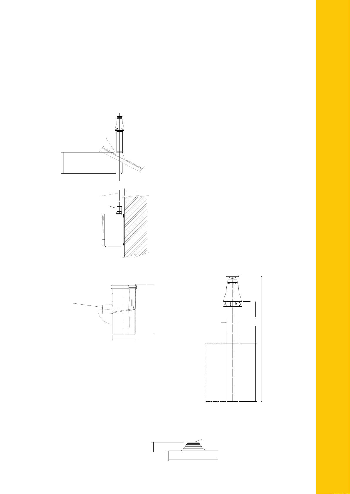
Vertical Concentric Flue Kit Option QP03
(For use when the flue is discharged vertically through the roof)
Typical single boiler installation – can also be used for multiple boilers, but each
must have its own flue system and terminals sparated a min of 300mm if at the
same height. Refer to the relevant British Standard if this is not the case.
Weathering Slate
Suitable for flat or
pitched roof (60
o
)
REMEHA QUINTA PRO | SELECTION, DESIGN AND INSTALLATION OF FLUE SYSTEMS
QP30/45 - 495mm
Additional components
required to suit site
details (within boiler
constraints)
Condense
Drain
QP3 0/45/65/90/115 =100mm
Kit Parts – KT00308
1 x Vertical Terminal – MG410086864
Detail of the Vertical 80/125mm Concentric Flue Kit Option QP03 (Part No KT00308)
25mm ID/32mmO/D
100mm
Condensate Drain
Part No. MG410085130
180mm
Can be cut down on site
to a minimum of 150mm
Retain the difference
between inner and outer
1 x Universal Roof seal Pack – VE001
1 x Condensate drain – MG410084472
RAL - 7021
Ral - 9016
Dn80
Dn125
(300mm)
755mm
1350mm
Detail of Standard weathering plate for 100mm to 150mm flue (Part No VE001)
flat or pitch roofs up to 60º
80mm approx
600mm X 500mm
Cut down to suit dia.
of Terminal in use
5
Quinta Pro 30 and 45 – 80/125mm Room
Sealed Calculated data to determine
maximum flue runs
(Calculation data based on flue products supplied by Remeha Commercial)
Table 1
Room Sealed
Calculation Data
Maximum overall
Quinta Pro 30
80/125mm
Metres 20 16
Quinta Pro 45
80/125mm
flue run
Reduction Length
Metres 1 1
for each 45° bend
Reduction Length
Metres 2 2
for each 90° bend
80/125mm Concentric Flue System Components for Room Sealed Operation
125 o/d
'L'
125 o/d
‘L’
Internal Seal (80mm)
Part No MG410027355
50
80 o/d
80 o/d
Standard length (cannot be cut)
'L' = 1000mm Part No MG410084486
'L' = 500mm Part No MG410084485
Standard length (cuttable length)
‘L’ = 1000mm Part No MG410082314
‘L’ = 500mm Part No MG410082313
Internal wall plate
Part No. MG410081302
110
25mm I/D - 32mm O/D
180mm
o
CE
Condensate drain Part No MG410084472
87-90
10
80mm o/d
45 Bend
Part No MG410084461
CE
125 i/d
95
145
125 i/d
80 o/d
o
90
Boiler short bend Part No MG41008410
o
90 Bend Part No MG410084460
126 i/d
210
115
Wall bracket
Part No MG410087863
PLEASE NOTE: All dimensions are in mm.
6
60 ctrs
Clamp band
Part No MG410087654
(one supplied with
each component
except MG410084810)
80/125mm -100/150mm
Concentric adaptor
Part No. MG410084475
158mm
Fall to boiler T 36m
Fall from boiler
Flue outlet
Quinta Pro 30/45 two pipe adaptor plate is
required to replace standard concentric fitting
(maximum
height)
Condensate drain
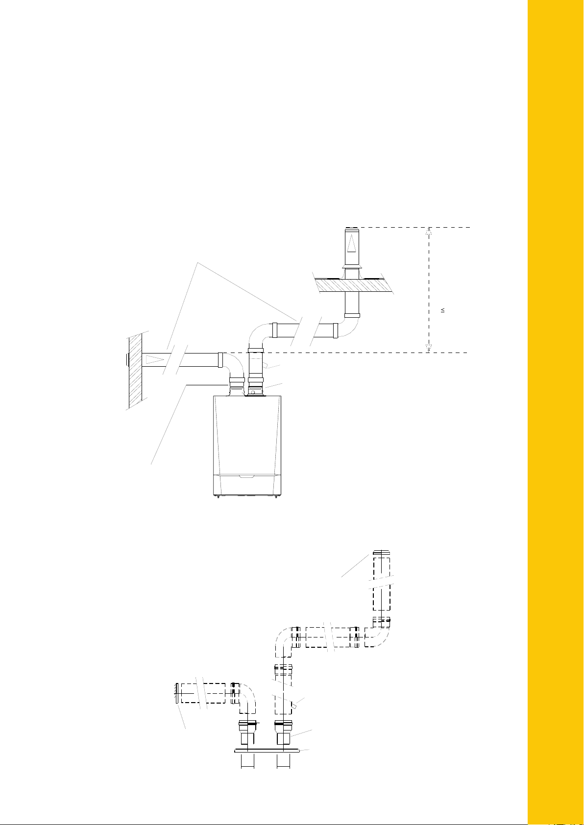
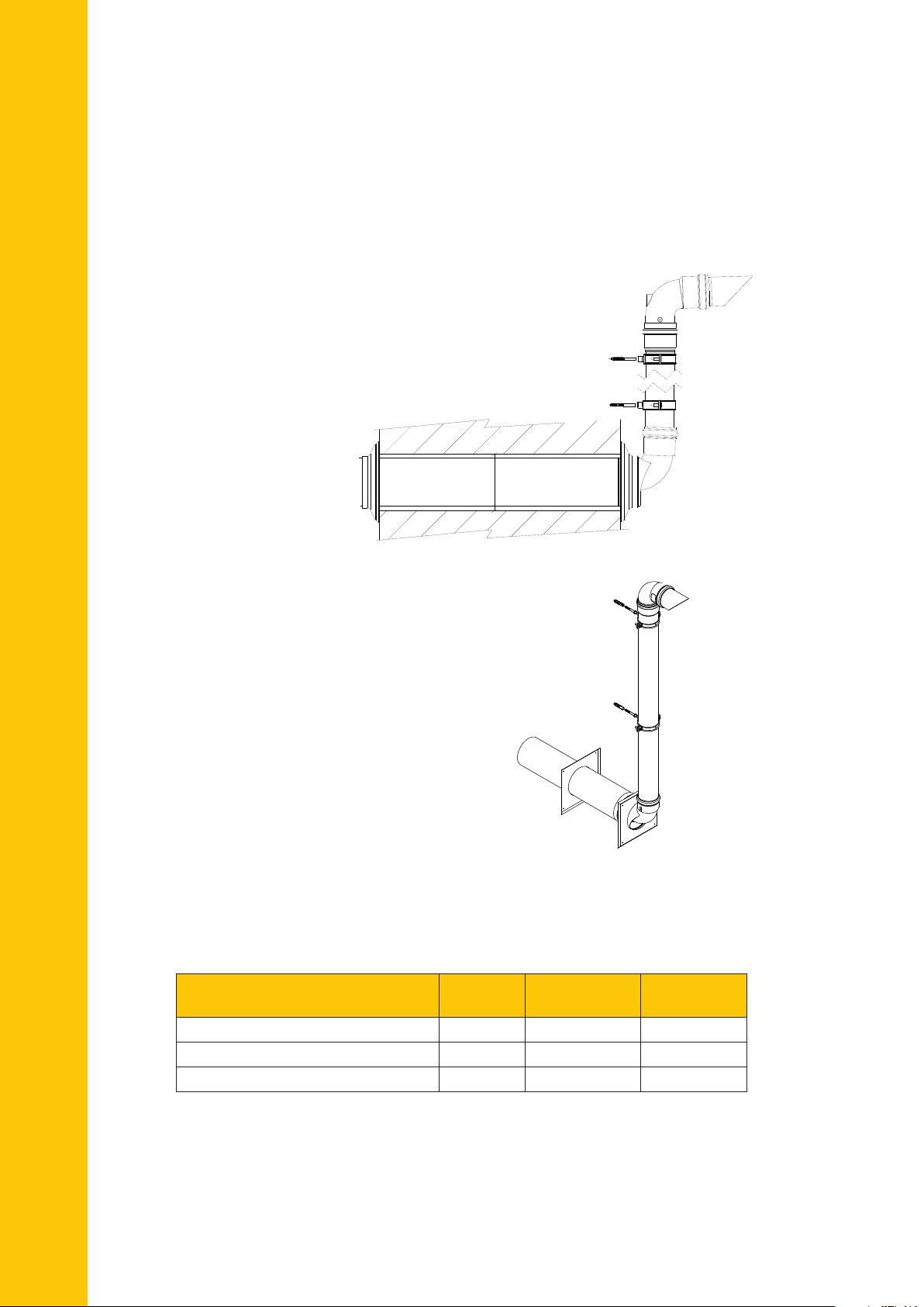
Quinta Pro 30 and 45 – Room Sealed,
100mm Two zone CLV Flue Kit Option QP04
(For use when the air inlet is drawn from low level and flue outlet discharged
vertically in a different pressure zone).
Typical single boiler installation – can also be used for multiple boilers, but each
must have its own flue system.
Please contact our technical department or refer to the Quinta Pro Installation
and Service Booklet for details on maximum flue lengths allowed when using
CLV installations.
REMEHA QUINTA PRO | SELECTION, DESIGN AND INSTALLATION OF FLUE SYSTEMS
100mm Aluminium single wall
flue and air inlet system
Air
inlet
100 / 80mm Reducers to adapt
boiler to suit 100mm system
if required.
Fall from boiler
Flue outlet
Fall to boiler T 36m
Condensate drain
Quinta Pro 30/45 two pipe adaptor plate is
required to replace standard concentric fitting
Kit Parts – KT032
1 x Flue connection – S100250
2 x Flue adaptor 80/100 – MG87127
1 x Flue terminal – PU001
1 x Air inlet – PU002
1 x Condensate drain – MG410085130
(maximum
height)
Detail of the 100mm Two Zone CLV Flue Kit Option QP04 (Part No KT032)
Flue terminal
Only parts named are in the kit
additional 100mm single wall pipe
and bends, shown dotted will be
needed to suit site requirements
(overall length to be within boiler
constraints)
Air inlet Guard
80mm
c/w bird guard
80mm
Condensate drain
100-80 mm Reducer x2
Two pipe adaptor
plate
7
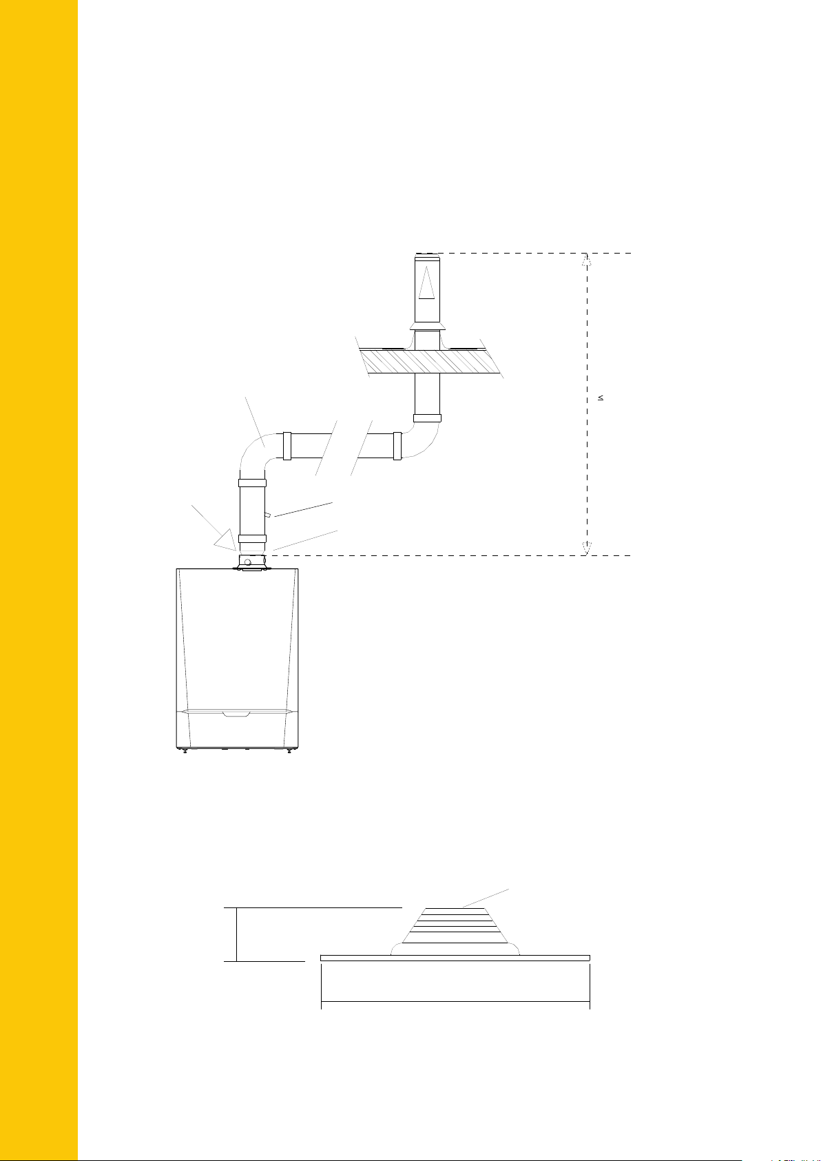
Quinta Pro 30 and 45 100mm Conventional
Fall to boiler
100 /
80mm Reducer to adapt
boiler to suit 100mm system
Flue outlet
T Max 36m
Condensate drain
(Maximum
height)
or Open Flue Systems
Typical single boiler installation – can also be used for multiple boilers with each
boiler having its own flue system. Please ensure that the overall route does not
exceed the maximum values in the table on page 9.
Flue outlet
100mm Aluminium single wall
flue system.
Air from
plant room
Fall to boiler
Condensate drain
100 /
boiler to suit 100mm system
80mm Reducer to adapt
T Max 36m
(Maximum
height)
Detail of Standard weathering plate for 100mm to 150mm flue (Part No VE001)
flat or pitch roofs up to 60º
Cut down to suit dia.
of flue.
80mm appox
600mm X 500mm
8
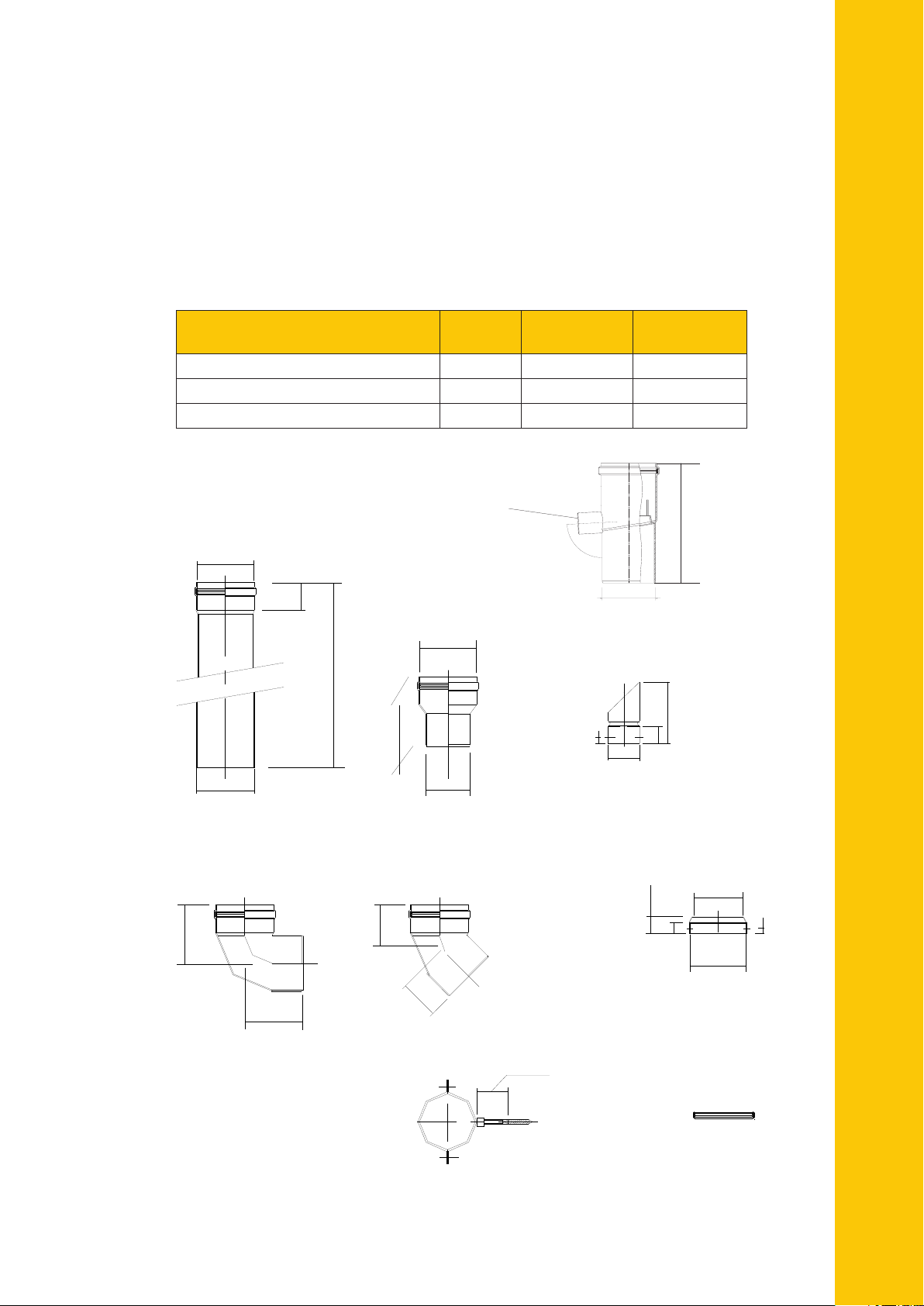
Quinta Pro 30 and 45 – 100mm Conventional
'L'
101 i/d
100 o/d
Standard length
'L'= 1000mm Part No. MG87062
'L'= 500mm Part No. MG87061
'L'= 250mm Part No. MG86060
105
105
90o Bend
Part No. MG87113
45o Bend
Part No. MG87103
76
76
125
101 i/d
80 o/d
Reducer 80mm spigot to 100mm
Part No. MG87127
Must be used on the QP30/45 flue socket
connection to adapt to 100mm
system
Silicon seal ring
Part No. MG87186
50
Mountng Bracket
Part No. MG87193
8mm x 45mm
Screw thread
25-55 mm
Note:
2 x 45° bends will off
set to 71mm centres
10 /d
95
30
20
Flue terminal c/w bird guard
Part No. PU001
Air Inlet guard
Part No. PU0 02
10
10
200
60
101 i/d
Top
1 i
101 i/d
95
Air Inlet guard
Part No. PU002
10
10
200
60
101 i/d
Top
or Open Flue Systems
(As the Boiler is fan assisted it makes no difference if the run is horizontal or
vertical but should terminate vertically as shown on page 8).
(Calculation data based on flue products supplied by Remeha).
Table 2
REMEHA QUINTA PRO | SELECTION, DESIGN AND INSTALLATION OF FLUE SYSTEMS
Open Flue Data Quinta Pro 30
Maximum overall flue run Metres 40 40
Reduction Length for each 45° bend Metres 1.4 1.4
Reduction Length for each 90° bend Metres 4.9 4.9
Quinta Pro 45
100mm
25mm ID/32mmO/D
100mm
180mm
100mm
Condensate Drain
Part No. MG410085130
PLEASE NOTE: All dimensions are in mm.
Silicon seal ring
Part No. MG87183
9
Min 150mm
Note: Can be extended with extra parts
see table.
Remeha Quinta Pro 30 & 45 Plume Kits
80/125mm Flue Kit Option QP05
(Calculations based on products supplied by Remeha Commercial)
Wall Depth – Max 500mm – Min 150mm
Terminal inner and outer can be cut to suit.
Note 1: 140mm diameter recess 15mm deep required
from the face of the inside wall face to allow if
clearance for the bend.
Note 2: Both the air intake and flue outlet
termination postions must comply with
current regulations and British Standards.
Flue can be taken directly
through rear outside wall
or discharged through
a side wall left or right.
Both must be within
the constraints in the
table below.
80/125mm Plume Management Kits
QP05 Part No. KT00335
PMK-Horizontal Terminal Kit
1. PMK Wall terminal
2. Boiler bend – not illustrated
3. Wall plates
4. 1000mm flue extension (80mm)
5. Support bracket (80mm)
6. 90° bend (80mm)
7. Flue outlet (80mm)
8. Bird guard
Core Drill Wall - 130mm Dia.
6
5
5
1
Note: Can be extended with extra parts
Min 150mm
see table.
8
7
4
Note: The horizontal terminal unit must be
installed with the outlet pointing vertically
upwards. External components are
constructed of black PP (plastic).
Horzontial terminal kit installed
3
3
80/125mm Plume Management details
Table 3
Quinta Pro 30
80/125mm
Quinta Pro 45
80/125mm
Maximum overall flue run Metres 37 23
Reduction Length for each 45° bend Metres 1.96 1.96
Reduction Length for each 90° bend Metres 2.25 2.25
The table shows the maximum lengths allowed which includes both the internal
concentric 80/125mm and the external 80mm. The bend from the top of the boiler
and the external 80mm bend have already been taken into account. Any bends
used must be taken from the total using the table above, this applies to the internal
80/125mm and the external 80mm.
The maximum horizontal run is 6 metres.
10
 Loading...