


QUINTA PRO RANGE
Suggested Schematics with Control and Power Wiring Details
HIGH EFFICIENCY |
FULLY MODULATING |
PREMIX BURNER |
ULTRA LOW NOx |
RECYCLABLE |
108.9% NCV ΔT 50/30°C |
BOILER CONTROL |
CLEAN COMBUSTION |
BREEAM EXCELLENT |
MATERIALS |
High efficiency wall hung condensing boiler with ultra low NOx emissions
QUINTA PRO RANGE OUTPUTS
QP30: 8.0 - 31.4 kW
QP45: 8.0 - 43.0 kW
QP65: 12.0 - 65.0 kW
QP90: 14.1 - 89.5 kW
QP115: 16.6 - 114.0 kW
DETAILS WIRING POWER AND CONTROL WITH SCHEMATICS SUGGESTED - RANGE PRO QUINTA REMEHA
Schematics with Control |
Page |
Control Options for the Quinta Pro Series of Boilers |
p3 |
External controls by others |
|
Simple Quinta Pro boiler domestic installation - |
p4-5 |
Typical ‘S’ plan, heating and hot water |
|
Single Quinta Pro boiler, heating only |
p6-7 |
Single Quinta Pro boiler, heating only with low loss header |
p8-9 |
Single Quinta Pro boiler, heating and priority hot water using a low loss header |
p10-13 |
and pump or valve kit |
|
Remeha supplied controls |
|
Single Quinta Pro boiler, heating only using the iSense controller |
p14-16 |
(room/weather compensation) |
|
Single Quinta Pro boiler, heating and Priority DHW using the iSense controller |
p17-19 |
(room or outside compensation) |
|
Multiple Quinta Pro boilers HTG only using a low loss header with the Celcia MC4 |
p20-21 |
and iSense (room or outside compensation) |
|
Multiple Quinta Pro boilers HTG and Priority DHW using a low loss header with |
p22-24 |
the Celcia MC4 and iSense (room or outside compensation) |
|
Multiple boilers, heating and hot water using a low loss header with the |
p25-30 |
iSense Pro controller (optimising/weather compensated control for dual |
|
heating zone and hot water from all or single boilers) |
|
Connecting multiple boilers with external control interlocks and alarm |
p31 |
and run signals |
|
Quinta Pro nominal flow rates and boiler resistances |
p31 |
Note: We supply the Grundfoss 25/80 (Part No. S101621) as standard for the full Quinta Pro range. This will alter due to changes in EU regulations. The Quinta Pro 30 will operate on speed 1, the 45 and 65 will operate on speed 2, and the 90 and 115 will operate on speed 3. They are intended to act as a shunt pump. In the layouts illustrated, they are designed to operate on a 20ºC Delta T . If using a pump without a low loss header, please take into account both the boiler and system resistance and also when being used in conjunction with a calorifier and low loss header. Contact our sales or technical departments for further assistance.
The hydraulic and control layouts illustrated in this brochure are for guidance only and must be used in conjunction with the Quinta Pro and iSense Pro installation and service manuals. They do not constitute a full system design. Remeha Commercial accept no liability for any loss or damage rising from any errors or omissions that may be inadvertently contained in this booklet.
When connecting a control cable to the OT terminals on the main control PCB, disconnect and remove the factory fitted lead connected to the IF01 PCB.
Some earths and neutrals are omitted for clarity.
All systems, mechanical and electrical, must be installed to the current regulations by a suitably qualified engineer.
2
Control Options for the Quinta Pro 30 / 45 / 65 / 90 and 115 series
The Remeha range of Quinta Pro boilers are supplied as standard with an “Open Therm” control interface which enables direct weather compensation using Remeha single and multi boiler controls. The customer can choose to use external control options supplied by others without affecting boiler performance.
Supplied by others
On/off control:
•Boiler requires a permanent 230v supply and is enabled using a volt free switch/relay.
The boiler will modulate its output to maintain the flow temperature setpoint, normally 80ºC, but can be adjusted on the boiler between 20ºC and 90ºC
0-10 volt control:
•Boiler requires a permanent 230v supply and is enabled and modulated using a 0-10 volt signal from a Building Management System or quality panel mounted optimiser/ compensator. The control can be flow temperature or percentage output based
•Temperature based example: if 56ºC flow is required from the boiler, the control will need to supply 5.6v. The output will be modulated to maintain a flow temperature of 56ºC
•Percentage based example: if the control logic requires that a boiler should be running at 33%, the control will need to supply 3.3v to the boiler. The boiler will run at 33% output with a variable flow temperature
•Applications - domestic/commercial and industrial installations, with a variety of heat emitters, DHW via calorifiers or plate heat exchangers, and installations where a variety of different temperature zones are required at the same time
Supplied by Remeha Commercial as optional extras
iSense Controller - Single/multi boiler weather compensating controller
•A simple to operate room/boiler mounted thermostat/timer which can be used with a combination of outside/room and flow temperature sensors to vary the boiler output (flow temp) to suit weather conditions. The iSense can be installed in a reference room and can also be mounted in a boiler when used in weather compensated mode.
It has a 7 day timer with multiple on/off and night setback periods, holiday function, frost protection and manual override
Celcia MC4
•Multiple boiler weather compensating controller with step control (up to 4 boilers) to be used in conjunction with the iSense controller
•The iSense can be mounted in a reference room, in the plant room or on the boiler
•The MC4 is mounted adjacent to the boiler group
iSense Pro - Multiple boiler weather compensating controller with sequence control (up to 8 boilers)
•Optimiser compensator which can provide 2 timed heating zones and uses a combination of outside, flow and room temperature to vary the boiler output (flow temp) to suit weather
conditions. Can also provide time control to DHW circuit. The iSense Pro controller is mounted in a wall box when used with the Quinta Pro and is complete with timer, night setback, frost protection and pump cycling protection. The iSense Pro controller will sequence and rotate the lead boiler on multiple installations. This controller also has the ability to accept remote extension timers, supplied as an optional extra, which will allow the heating system to run
on daytime compensation outside the normal timed settings without need for access or interference to the boiler or controller. Ideal for school lettings/night classes etc.
Note: We do not advise using a combination of external and built-in controls as in most cases there can be no interface between them; it is likely they will ‘conflict’ with each other
and neither will work properly. The exception to this is when using the iSense Pro kit KT1154 in conjunction with a Remote BMS controller (see page 31).
3
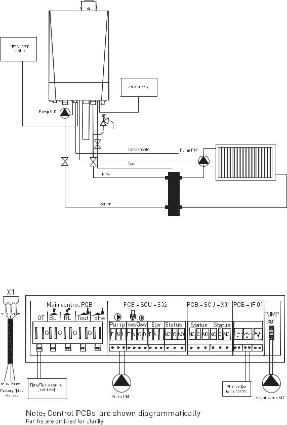
Simple Quinta Pro boiler domestic installation Typical ‘S’ plan, heating and hot water
(Time and temperature control by others)
Power Supply
•Boiler requires a permanent 230v single phase supply fused at 6.3 amps connected to the factory fitted fly lead
Boiler Control Settings
(see 5.7.2 in technical documentation)
•Set boiler code P1 to the required flow temp i.e. 80 = 80ºC (system design requirements)
•Boiler will recognise the control being used
•Use the zone valve end switches to provide the volt free switch pair on OT on the main control PCB to enable the boiler
•Boiler output will vary between 18% part load set point and 100% full load set point to achieve the boiler flow set point (code P1)
System Components
(not supplied)
•Simple two channel time clock providing 230v switched supplies to control heating and domestic hot water
•System pump
•Cylinder thermostat
•Room thermostat
•HTG and DHW zone valves c/w a single end switch (closes on valve fully open)
•Wiring centre
Note:
1.Maintain polarity on all connections
2.Some Neutral and Earth connections have been omitted for clarity
3.The schematic is for guidance only and does not constitute a design
4.Heating and hot water can be operated independently or simultaneously with this layout provided the control selected will allow it
4

Single Quinta Pro boiler, heating and domestic hot water, using a simple ‘S’ Plan
QP 001S
O
Shunt
QP 001SA
5
Single Quinta Pro boiler, heating only (Time and temperature control by others)
Power Supply
•Boiler requires a permanent 230v single phase supply fused at 6.3 amps connected to the factory fitted fly lead
Boiler Interlocks
(for pressure switches etc.)
•Safety Interlock - remove the existing link and fit volt free switch pair to BL on the main control PCB. If the circuit is open the boiler will go to a shut down mode displaying code 9 and will restart when the circuit is closed
Indication Controls
(to report actual function)
•Common Alarm - volt free relay on SCU-X01 (see boiler manual for full details)
•Boiler Run - volt free relay on SCU-X01 (see boiler manual for full details)
Boiler Control Settings
(see 5.7.2 in technical documentation)
•Connect the external controls (volt free) to the OT terminals on the main control PCB (on/off).
Boiler will modulate to the set point set in P1 or the 0 -10v terminals on the IF-01.
Control option based on temperature or output can be adjusted on the jumper on the IF-01. (See installation manual for full details)
•Boiler will recognise the type of control being used
•Set boiler code P1 to the required flow temp i.e. 80 = 80ºC (system design requirements)
•Pump: connect the heating pump to terminals shown on the PCB SCU - S02 max 400Va
(1.5 amp). Alternatively, pump can be connected to the fly lead supplied with the boiler to plug X81; this a max duty of 200w (0.8 amp)
6

Single Quinta Pro boiler, heating only
QP 002
QP 002A
7
Single Quinta Pro boiler, heating only with low loss header (Time and temperature control by others)
Power Supply
•Boiler requires a permanent 230v single phase supply fused at 6.3 amps connected to the factory fitted fly lead
Boiler Interlocks
(for pressure switches etc.)
•Safety Interlock - remove the existing link and fit volt free switch pair to BL on the main control PCB. If the circuit is open the boiler will go to a shut down mode displaying code 9 and will restart when the circuit is closed
Indication Controls
(to report actual function)
•Common Alarm - volt free relay on SCU-X01 (see boiler manual for full details)
•Boiler Run - volt free relay on SCU-X01 (see boiler manual for full details)
Boiler Control Settings
(see 5.7.2 in technical documentation)
•Boiler will recognise the type of control being used
•Set boiler code P1 to the required flow temp i.e. 80 = 80ºC (system design requirements)
•Connect the external controls (volt free) to the OT terminals on the main control PCB
(on/off). Boiler will modulate to the set point set in P1 or the 0 -10v terminals on the IF01. Control option based on temperature or output can be adjusted on the jumper on the IF01. (See installation manual for full details)
•Pumps: connect pump PM1 to the heating pump terminals shown on the PCB SCU - S02 max 400Va (1.5 amp). Connect the shunt pump SH1 to the pump fly lead supplied with the boiler to plug X81
8
Single Quinta Pro boiler, heating only with low loss header
QP 003
QP 003A
9
Single Quinta Pro boiler, heating with priority hot water using a low loss header and pump or valve kit
(Time and temperature control by others)
Power Supply
•Boiler requires a permanent 230v single phase supply fused at 6.3 amps connected to the factory fitted fly lead
Boiler Interlocks
(for pressure switches etc.)
•Safety Interlock - remove the existing link and fit volt free switch pair to BL on the main control PCB. If the circuit is open the boiler will go to a shut down mode displaying code 9 and will restart when the circuit is closed
Indication Controls
(to report actual function)
•Common Alarm - volt free relay on SCU-X01 (see boiler manual for full details)
•Boiler Run - volt free relay on SCU-X01 (see boiler manual for full details)
Boiler Control Settings
(see 5.7.2 in technical documentation)
•Boiler will recognise the type of control being used
•Set boiler code P1 to the required flow temp i.e. 80 = 80ºC (system design requirements)
•Connect the external controls (volt free) to the OT terminals on the main control PCB
(on/off). Boiler will modulate to the set point set in P1
•Pumps: connect pump PM1 to the heating pump terminals shown on the PCB SCU - S02 max 400Va (1.5 amp). Connect the shunt pump SH1 to the fly lead supplied with the boiler to plug X81 max 200w (0.8 amp). On pump installations, connect the shunt pump to the terminals shown; a contactor or relay will be required if loading exceeds 1.5 amps
•3-way valve: on the 3-way valve option, connect the valve to the terminals shown on the PCB
SCU – S02
Important:
When using the Remeha supplied low loss header and pump kit and the DHW diverting valve or primary pump kit, the calorifier must be sited within 3M of the boiler. In both cases, the DHW cylinder must be a high recovery unit capable of accepting the full or adjusted DHW output of the boiler being used (reference parameter P18).
10
 Loading...