


EN
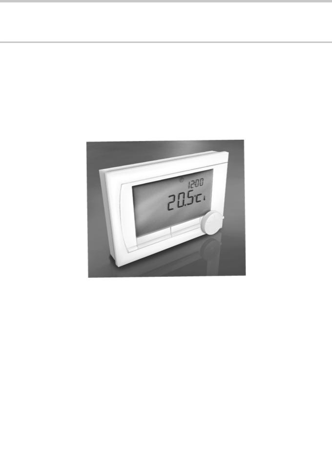
Digital timer thermosatat
iSense
Installation and
Service Manual
120666-AG

Contents
1 |
Preface ........................................................................................................ |
|
|
4 |
|
1.1 |
General |
.................................................................. |
4 |
2 |
Location of the installation ........................................................................ |
|
|
5 |
|
2.1 |
Position of the regulator ...................................... |
5 |
|
|
2.2 |
Installation and connection ................................. |
6 |
|
|
2.3 |
Location of the outside sensor ........................... |
7 |
|
|
2.4 |
Room sensor ......................................................... |
7 |
|
3 |
Start-up ........................................................................................................ |
|
|
8 |
|
3.1 |
Fitted control unit ................................................. |
8 |
|
|
|
3.1.1 |
Meaning of the symbols on the display ................... |
8 |
|
|
3.1.2 |
Functions of the keys .............................................. |
9 |
|
3.2 |
Setting language, time and date .......................... |
9 |
|
|
3.3 |
Default setting ....................................................... |
9 |
|
4 |
Setting ....................................................................................................... |
|
|
11 |
|
4.1 |
Changing the settings ........................................ |
11 |
|
|
|
4.1.1 |
Defining or modifying a timer program .................. |
11 |
|
|
4.1.2 |
Setting continuous temperatures .......................... |
12 |
|
|
4.1.3 |
Setting the holiday mode ....................................... |
13 |
|
|
4.1.4 |
Group control ........................................................ |
13 |
|
4.2 |
Operating the controller ..................................... |
14 |
|
|
|
4.2.1 |
Selecting a program .............................................. |
14 |
|
|
4.2.2 |
Temporarily changing the temperature ................. |
14 |
|
|
4.2.3 |
Fireplace mode ..................................................... |
15 |
|
|
4.2.4 |
Information ............................................................ |
15 |
|
|
4.2.5 |
Groups .................................................................. |
15 |
|
4.3 |
Changing usage settings ................................... |
16 |
|
|
|
4.3.1 |
Setting the display ................................................. |
16 |
|
|
4.3.2 |
Setting button locking ............................................ |
16 |
|
|
4.3.3 |
Setting the language ............................................. |
16 |
|
|
4.3.4 |
Setting the user level ............................................. |
16 |
|
|
4.3.5 |
Resetting factory settings ...................................... |
17 |
|
|
4.3.6 |
Calibration ............................................................. |
17 |
4.3.7Restoring a connection with the base station (Only
controller RF) |
........................................................17 |
4.3.8Connecting extra RF sensors (Only controller
|
RF) ........................................................................ |
17 |
4.3.9 |
Setting the time and date ...................................... |
17 |
1 |
|
|
030211 - 120666-AG |
|
|
||
|
|

Contents |
|
|
4.3.10 |
Comfort correction ................................................. |
18 |
4.3.11 |
Legionella function ................................................ |
18 |
4.3.12 |
Controlling the tap water temperature ................... |
18 |
4.3.13 |
Central heating settings ........................................ |
20 |
4.3.14 |
Frost protection - System ...................................... |
21 |
4.3.15 |
Frost protection - Room ........................................ |
21 |
5 |
Selecting the control strategy ................................................................. |
22 |
|
|
5.1 |
Six control strategies ......................................... |
22 |
|
5.2 |
Setting the control strategy ............................... |
23 |
|
5.3 |
Specific settings for weather-compensated |
|
|
|
control .................................................................. |
24 |
|
5.4 |
Heating curve - For example .............................. |
25 |
6 |
Installer settings ....................................................................................... |
|
|
26 |
|
6.1 |
Telephone number for service messages and |
|
|
|
|
failure signals ...................................................... |
26 |
|
|
6.2 |
Service messages on or off ............................... |
26 |
|
|
6.3 |
PIN code for menus for the installer and |
|
|
|
|
system |
................................................................. |
26 |
|
6.4 |
Digital input ......................................................... |
26 |
|
|
|
6.4.1 .............................................................. |
Operation |
26 |
|
|
6.4.2 .............................................................. |
Examples |
27 |
|
6.5 |
Boiler Setting ...................................................... |
29 |
|
7 |
Messages .................................................................................................. |
|
30 |
|
7.1 |
Error messages ................................................... |
30 |
|
7.2 |
Maintenance message ........................................ |
31 |
|
7.3 |
Incidents and solutions ...................................... |
31 |
8 |
Menu / Technical data .............................................................................. |
|
33 |
|
8.1 |
Menu structure .................................................... |
33 |
|
8.2 |
Technical characteristics ................................... |
35 |
2 |
|
|
030211 - 120666-AG |
|
|
||
|
|

3 |
|
|
030211 - 120666-AG |
|
|
||
|
|
iSense |
1. Preface |
1Preface
1.1General
The Remeha iSense is a timer thermostat with many enhanced functions.
The controller is supplied in a OpenTherm and RF variant:
4iSense OpenTherm.
4iSense OpenTherm RF(Wireless). With the iBase RF transmitter.
This installation and service manual describes all the functions of the iSense. (OpenTherm) (RF)
030211 - 120666-AG |
|
|
4 |
|
|
||
|
|
2. Location of the installation |
iSense |
2Location of the installation
2.1Position of the regulator
Controller OpenTherm and controller RF
The controller is set to room control by default. The controller can be installed on an inside wall or in a boiler, if the boiler is suitable for this. This means that the inside temperature is used to control the central heating. It is therefore best to locate the controller on an internal wall in the room in which you spend the most time, such as the living room.
For Germany: The controller is set to weathercompensated control by default.
Only controller RF
The following also applies for the controller RF:
4Position the controller at least 1 metres from equipment with electromagnetic emissions (Washing machines, dryers, cordless telephones, televisions, computers, microwave ovens etc).
4Position the controller so that it has good reception.
Take account of the fact that objects containing metal will affect the reception. These include steel-reinforced concrete, mirrors and windows with a metal coating, insulation films, etc.
CAUTION
Wireless range of controller RF
The range of the controller RF in buildings is generally 30 metres.
Note!
This value is purely an indication! The actual range of the RF signal depends heavily on the local environment. Remember that the number of walls and ceilings (regardlessofwhethertheycontainmetalornot)canhave a considerable impact on reception. Other objects that contain metal may also impact the reception.
These include steel-reinforced concrete, mirrors and windows with a metal coating, insulation films, etc.
The signal strength can be viewed via Menu >
Information.
5 |
|
|
030211 - 120666-AG |
|
|
||
|
|

iSense |
2. Location of the installation |
2.2Installation and connection
Before you can connect the controller, you must first:
4Adjust the boiler so that it can be connected to a OpenTherm controller. See the installation and service manual for the boiler.
4Shut down the boiler.
To do this, proceed as follows:
1. Open the housing by pulling the front and the base plate apart.
2X
2X
2 
 3
3
4


 1
1
T001035-C
OT
DIGI
2.Attach the base plate to the wall using the screws and plugs supplied. Ensure that the OpenTherm connecting wires for the boiler are poking through the hole in the base plate.
3.(Only controller OpenTherm) Connect the controller to the
OpenTherm connection of the boiler, and to the OT connection of the controller. OpenTherm is not sensitive to polarity. The wires are interchangeable.
 O
O
T001036-D
030211 - 120666-AG |
|
|
6 |
|
|
||
|
|

2. Location of the installation |
iSense |
4. (Only controller OpenTherm) Place 3 AA batteries in the controller if necessary. These are not supplied. The batteries ensure that the clock keeps running when the boiler is switched off. The batteries also power the backlights of controllers for boilers that do not have OpenTherm Smart Power. If you have a boiler with Smart Power, then the backlight of the controller also works without batteries.
(Only controller RF) Insert 3 AA batteries into the controller. These are required to operate the controller RF.
|
The set programs will be retained if the boiler or controller |
|
is switched off (Even if no batteries are inserted). |
|
The controller is now connected and ready for use. The |
|
base station must now be fitted for the controller RF. |
T001042-C |
Consult the base station manual for this. |
2.3Location of the outside sensor
>2,5 |
M |
|
An outside temperature sensor is not supplied as standard with the controller. You only require this sensor if you want weathercompensated control of the inside temperature.
The following guidelines apply with regard to choosing a location for an outside temperature sensor:
4Install the outside sensor on the north or north-west side of the home, away from direct sunlight.
4The sensor must be positioned at least 2,5 metres above ground level.
4Do not install the outside temperature sensor next to a window, door, vent etc
Consult the documentation for your boiler for information on connecting an outside temperature sensor.
T001043-B
2.4Room sensor
(Only controller RF)
A RF room sensor is optionally available for a controller RF. This sensor replaces the internal controller sensor.
7 |
|
|
030211 - 120666-AG |
|
|
||
|
|
iSense |
3. Start-up |
3Start-up
3.1Fitted control unit
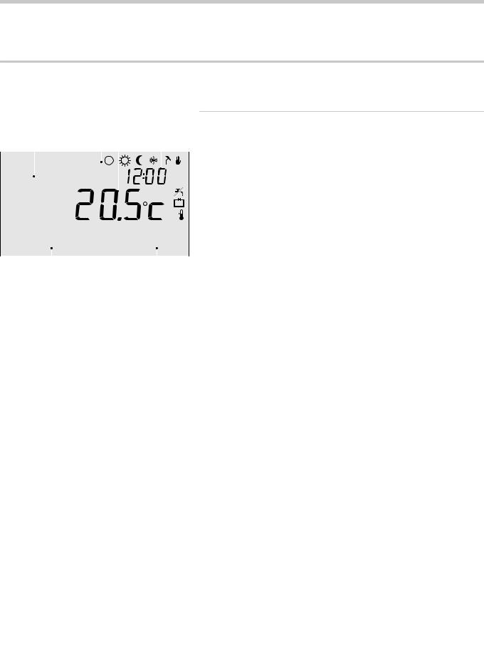
3.1.1.Meaning of the symbols on the display
|
Textbox |
Pictograms Temperature Time |
|||||||
|
menus |
|
|
|
|
|
|
|
|
|
|
|
|
|
|
|
|
|
|
|
|
|
|
|
|
|
|
|
|
|
|
|
|
|
|
|
|
|
|
|
|
|
|
|
|
|
|
|
|
|
|
|
|
|
|
|
|
|
|
|
|
|
|
|
|
|
|
|
|
|
|
|
|
|
|
|
|
|
|
|
|
|
|
|
|
|
|
|
|
Menu |
|
|
Program |
|
|
|
|
||||
|
|
|
|
|
|
|
|
|
|
|
|
Mode button A |
Mode button B |
||||
|
|
|
|
|
T001034-04-A |
Pictograms
s Clock program active u Clock program A active t Clock program B active
! Continuous day temperature z Continuous night temperature
] Frost protection
{Summer mode
E |
Manual setting |
xVacation program
T DHW standby function switched off
\Set temperature
HMeasured temperature
ZOutside temperature measured
IHeating System
Pictograms not shown
DController requesting heat
IN Central heating boiler on for hot water
ID Central heating boiler on for central heating
dButton locking enabled
p |
Group 1 selected |
qGroup 2 selected
rElectricity production
Warning symbols
e Check the water pressure in the installation
?Boiler service required
v |
Battery in controller almost empty |
c |
General warning symbol |
wNo wireless connection
030211 - 120666-AG |
|
|
8 |
|
|
||
|
|
3. Start-up |
iSense |
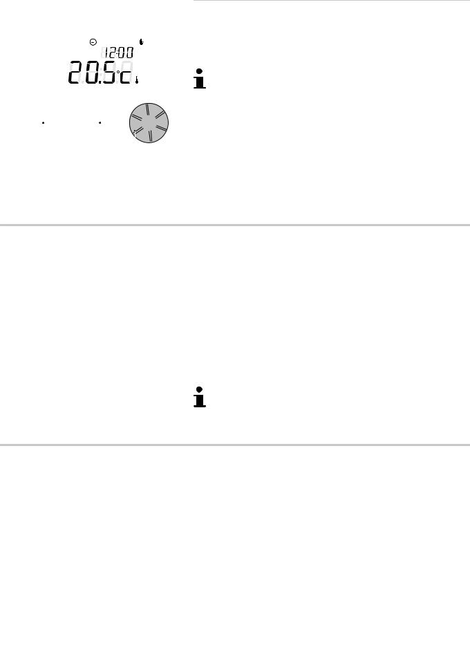
3.1.2.Functions of the keys
|
|
|
|
|
|
|
|
The controller is menu-controlled, which means it is very simple to |
|
|
|
|
|
|
|
|
|
operate. |
|
|
|
|
|
|
|
|
|
|
|
|
|
|
|
|
|
|
|
|
|
|
|
|
|
|
|
|
|
It only has three buttons. |
|
|
|
|
|
|
|
|
|
4 |
The function of button A and button B depends on the |
|
|
|
|
|
|
|
|
|
task you are carrying out. |
|
|
|
|
|
|
|
|
4 |
The function is shown in the display immediately |
|
|
|
|
|
|
|
|
|
above the buttons. |
|
|
|
|
|
|
|
|
|
|
|
|
|
|
|
|
|
|
4 |
Button C is a push-turn button. |
|
|
|
|
|
|
|
|
||
|
|
|
|
|
|
|
|
4 |
You press it to confirm choices (Such as menu |
|
|
|
|
|
|
|
|
||
A |
|
B |
|
|
|||||
|
|
|
selections). |
||||||
|
|
|
|
|
C |
|
|||
|
|
|
|
|
|
|
|||
|
|
|
|
|
|
|
T000059-B |
4 |
By turning it you can perform various tasks such as |
|
|
|
|
|
|
|
|
|
scrolling through menus or changing values such as |
(Temperature Time Date Language).
3.2Setting language, time and date
When you connect the controller, the language selection menu appears.
1.Select the desired language by pressing button C, and then press button C to confirm.
2.Follow the instructions on the display to select the time, year, month and day.
The controller is now connected and ready for use. The default clock
program is activated after installation. ¼ "Default setting", page 9
The temperature is now controlled by this clock program.
The controller automatically switches between summer and winter time.
3.3Default setting
The controller is set to room control by default (Central heating is controlled on the basis of the inside temperature). Weathercompensated control of the boiler is also possible (on the basis of the outside temperature).
Programme schedule
The default clock program sets the temperature daily as follows:
406.00 - 19.00: 20
419.00 - 23.00: 21
423.00 - 06.00: 15 + T
9 |
|
|
030211 - 120666-AG |
|
|
||
|
|
iSense |
3. Start-up |
You can of course adapt the clock programs to your own
requirements. ¼ "Defining or modifying a timer program", page 11
030211 - 120666-AG |
|
|
10 |
|
|
||
|
|

4. Setting |
iSense |
4Setting
4.1Changing the settings
4.1.1.Defining or modifying a timer program
Time |
MO |
TU |
WE |
TH |
FR |
SA |
SU |
7:00 |
20 |
20 |
20 |
20 |
20 |
|
|
9:00 |
15 |
15 |
|
15 |
15 |
20 |
20 |
11:00 |
|
|
|
|
|
|
|
13:00 |
|
|
|
|
|
|
|
15:00 |
|
|
|
|
|
15 |
|
17:00 |
|
|
|
|
|
|
|
19:00 |
21 |
|
21 |
21 |
21 |
21 |
|
21:00 |
|
21 |
|
|
|
|
|
23:00 |
15 |
15 |
15 |
|
|
|
15 |
0:00 |
|
|
|
15 |
15 |
15 |
|
The timing program automatically controls the room temperature on the basis of set time intervals and can be separately regulated for each day of the week. You can adjust the default clock program or enter a completely new program.
The controller starts pre-heating prior to the set time by default. This allows the room to reach the desired temperatureatthecorrecttime.Tochangethepre-heating
setting ¼ "Central heating settings", page 20.
SettingtheclockprogramindirectlydetermineswhenDHW
standby is active ¼ "Controlling the tap water temperature", page 18.
Summary table
It is useful to draw up your own overview with switch times (What temperature does it need to be and when in your home ?).
This of course depends on who is at home and when, and what time you get up, etc. You can set 6 switch times per day. See the table on this page.
Creating a new clock program
1.Select in the controller: Menu > Program > Clock prog. > New.
2.Select an initial program if appropriate (Home in daytime, Home midweek or Home at weekends). You can now create your own clock program based on this program. Press button C to confirm.
3.Go to the day you want to set the clock program for. Press button C to confirm.
11 |
|
|
030211 - 120666-AG |
|
|
||
|
|
 Loading...