


P520
Table of contents
 Loading...
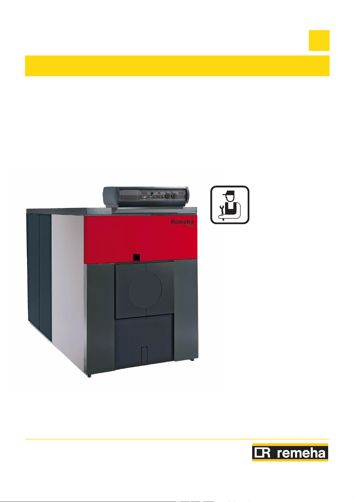
Remeha
Fuel oil/gas boilers
P 520
EN
Installation and
Service Manual
300016859-001-A
63115
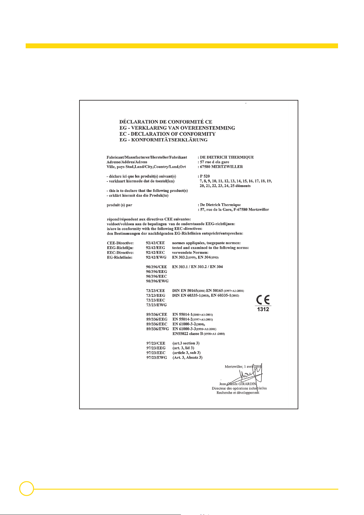
Declaration of conformity 1
The appliance complies with the standard model described in
declaration of compliance 1. It is manufactured and distributed
pursuant to the requirements of European Directives. The original of
the declaration of compliance is available from the manufacturer.
C001878
2
P 520 02/04/08 - 300016859-001-A

Contents
1 General . . . . . . . . . . . . . . . . . . . . . . . . . . . . . . . . . . . . . . . . . . . . . . . . . . . . . . . . . . . . . . . . . . . . . . . . . . . . . . . . .4
2 Description. . . . . . . . . . . . . . . . . . . . . . . . . . . . . . . . . . . . . . . . . . . . . . . . . . . . . . . . . . . . . . . . . . . . . . . . . . . . . .5
2.1 Technical characteristics . . . . . . . . . . . . . . . . . . . . . . . . . . . . . . . . . . . . . . . . . . . . . . . . . . . . . . . . . . . . . . . . . . . . . . . . . . . . . . . . . .6
2.2 Main dimensions. . . . . . . . . . . . . . . . . . . . . . . . . . . . . . . . . . . . . . . . . . . . . . . . . . . . . . . . . . . . . . . . . . . . . . . . . . . . . . . . . . . . . . . . .7
3 Installing the boiler . . . . . . . . . . . . . . . . . . . . . . . . . . . . . . . . . . . . . . . . . . . . . . . . . . . . . . . . . . . . . . . . . . . . . . .9
3.1 Boiler location . . . . . . . . . . . . . . . . . . . . . . . . . . . . . . . . . . . . . . . . . . . . . . . . . . . . . . . . . . . . . . . . . . . . . . . . . . . . . . . . . . . . . . . . . . .9
3.2 Ventilation. . . . . . . . . . . . . . . . . . . . . . . . . . . . . . . . . . . . . . . . . . . . . . . . . . . . . . . . . . . . . . . . . . . . . . . . . . . . . . . . . . . . . . . . . . . . .10
4 Mounting . . . . . . . . . . . . . . . . . . . . . . . . . . . . . . . . . . . . . . . . . . . . . . . . . . . . . . . . . . . . . . . . . . . . . . . . . . . . . .10
5 Hydraulic connections . . . . . . . . . . . . . . . . . . . . . . . . . . . . . . . . . . . . . . . . . . . . . . . . . . . . . . . . . . . . . . . . . . .11
5.1 Dimensional information required. . . . . . . . . . . . . . . . . . . . . . . . . . . . . . . . . . . . . . . . . . . . . . . . . . . . . . . . . . . . . . . . . . . . . . . . . . .11
5.2 Important recommendations for connecting the boiler to the heating circuit . . . . . . . . . . . . . . . . . . . . . . . . . . . . . . . . . . . . . . . . . .12
5.3 Filling the system . . . . . . . . . . . . . . . . . . . . . . . . . . . . . . . . . . . . . . . . . . . . . . . . . . . . . . . . . . . . . . . . . . . . . . . . . . . . . . . . . . . . . . .13
5.4 Sludge removal. . . . . . . . . . . . . . . . . . . . . . . . . . . . . . . . . . . . . . . . . . . . . . . . . . . . . . . . . . . . . . . . . . . . . . . . . . . . . . . . . . . . . . . . .13
6 Chimney connection . . . . . . . . . . . . . . . . . . . . . . . . . . . . . . . . . . . . . . . . . . . . . . . . . . . . . . . . . . . . . . . . . . . . .14
6.1 Flue size . . . . . . . . . . . . . . . . . . . . . . . . . . . . . . . . . . . . . . . . . . . . . . . . . . . . . . . . . . . . . . . . . . . . . . . . . . . . . . . . . . . . . . . . . . . . . .14
6.2 Chimney connection . . . . . . . . . . . . . . . . . . . . . . . . . . . . . . . . . . . . . . . . . . . . . . . . . . . . . . . . . . . . . . . . . . . . . . . . . . . . . . . . . . . . .14
7 Fuel-oil or gas connections . . . . . . . . . . . . . . . . . . . . . . . . . . . . . . . . . . . . . . . . . . . . . . . . . . . . . . . . . . . . . . .15
8 Electrical connections . . . . . . . . . . . . . . . . . . . . . . . . . . . . . . . . . . . . . . . . . . . . . . . . . . . . . . . . . . . . . . . . . . .15
9 Maintenance. . . . . . . . . . . . . . . . . . . . . . . . . . . . . . . . . . . . . . . . . . . . . . . . . . . . . . . . . . . . . . . . . . . . . . . . . . . .15
9.1 Sweeping . . . . . . . . . . . . . . . . . . . . . . . . . . . . . . . . . . . . . . . . . . . . . . . . . . . . . . . . . . . . . . . . . . . . . . . . . . . . . . . . . . . . . . . . . . . . .15
9.2 Cleaning the casing material . . . . . . . . . . . . . . . . . . . . . . . . . . . . . . . . . . . . . . . . . . . . . . . . . . . . . . . . . . . . . . . . . . . . . . . . . . . . . .18
9.3 Precautions required in the case of long boiler stops (one or more years) . . . . . . . . . . . . . . . . . . . . . . . . . . . . . . . . . . . . . . . . . . .18
9.4 Precautions required if the heating is stopped when there is a risk of freezing . . . . . . . . . . . . . . . . . . . . . . . . . . . . . . . . . . . . . . . .18
10 Burner maintenance . . . . . . . . . . . . . . . . . . . . . . . . . . . . . . . . . . . . . . . . . . . . . . . . . . . . . . . . . . . . . . . . . . . . .18
11 System maintenance . . . . . . . . . . . . . . . . . . . . . . . . . . . . . . . . . . . . . . . . . . . . . . . . . . . . . . . . . . . . . . . . . . . . .18
11.1 Water level . . . . . . . . . . . . . . . . . . . . . . . . . . . . . . . . . . . . . . . . . . . . . . . . . . . . . . . . . . . . . . . . . . . . . . . . . . . . . . . . . . . . . . . . . . . .18
11.2 Draining . . . . . . . . . . . . . . . . . . . . . . . . . . . . . . . . . . . . . . . . . . . . . . . . . . . . . . . . . . . . . . . . . . . . . . . . . . . . . . . . . . . . . . . . . . . . . .18
12 Rating plate . . . . . . . . . . . . . . . . . . . . . . . . . . . . . . . . . . . . . . . . . . . . . . . . . . . . . . . . . . . . . . . . . . . . . . . . . . . .19
13 Spare parts - P 520 . . . . . . . . . . . . . . . . . . . . . . . . . . . . . . . . . . . . . . . . . . . . . . . . . . . . . . . . . . . . . . . . . . . . . .20
02/04/08 - 300016859-001-A P 520
3

1 General
This product will be marketed in the following European Union
member states :
NL - BE - ES - GB - HU - SE
with a gas burner of the associated category.
Symbols used
Caution danger
Specific information Information must be kept in mind to maintain comfort
Reference Refer to another manual or other pages in this instruction manual
Z
Warning
The boiler shall be assembled and installed by a qualified
professional only.
For a proper operating of the boiler, follow carefully the
instructions.
Risk of injury and damage to equipment. Attention must be paid to the warnings on
safety of persons and equipment
4
P 520 02/04/08 - 300016859-001-A
2 Description
The boilers of the P 520 range are pressurised hot water boilers
designed for connecting to a flue pipe which require a separate
automatic fuel-oil or gas burner.
The useful power of P 520 boilers is between 754 and 1450 kW.
Models available
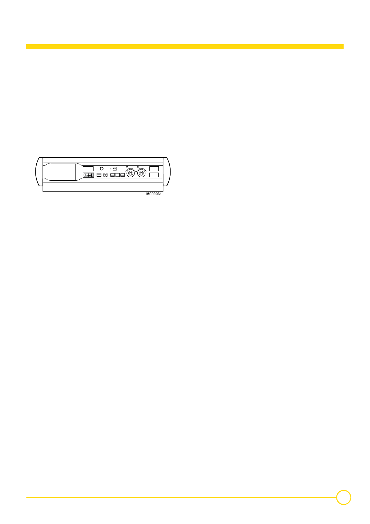
Boiler with control panel, which may be fitted with an optional
Rematic 2945 C3K control unit for heating only or heating and
domestic hot water production.
02/04/08 - 300016859-001-A P 520
5

2.1 Technical characteristics
Maximum operating pressure : 7.5 bar
Boiler thermostat setting : 30 to 90°C
Safety thermostat setting : 110 °C
Boiler P 520-13 P 520-15 P 520-17 P 520-19 P 520-21 P 520-23 P 520-25
Useful output kW 696 to 754 812 to 870 928 to 986
Power input kW 773 to 838 902 to 967
Number of sections 13 15 17 19 21 23 25
Water content l 617 693 769 845 943 1019 1095
∆ T = 10K
Water resistance
Pressure in the
furnace for nozzle
pressure = 0
Flue gas temperature
Mass flue gas flow
(1) (2)
rate
Combustion chamber
Maintenance
consumption*
Shipping weight kg 3000 3364 3756 4124 4538 4930 5297
∆ T = 15K 25.8 34.7 13.5 18.5 24 29 35
∆ T = 20K 14.4 19.4 7.6 10.4 13.4 16.2 19.6
(1) (3)
Fuel oil
Gas 1120 1280 1440 1590 1750 1910 2070
Inscribed diameter mm 614 614 614 614 614 614 614
Equivalent diameter mm 694 694 694 694 694 694 694
Depth mm 1372 1594 1816 2038 2300 2522 2744
Volume
∆ T = 30K % 0.08 0.07 0.07 0.07 0.06 0.06 0.06
mbar
mbar 2.2 2.4 2.6 2.85 3.1 3.3 3.5
K <190 <190 <190 <190 <190 <190 <190
Kg/h
m
57.6 77.6 30.2 41.4 53.6 64.8 78.4
1070 1220 1370 1520 1670 1820 1970
3
0.53 0.61 0.70 0.78 0.88 0.96 1.05
1031 to
1096
1044 to
1102
1160 to
1224
1160 to
1218
1289 to
1353
1276 to
1334
1418 to
1482
1392 to
1450
1547 to
1611
*Maintenance consumption: total heat emission when the burner is
off as a percentage of the nominal input power when the difference
between the mean boiler temperature and the room temperature is
30 K.
(1)
Nominal operation (top boiler power)
)
(2
CO2 = 13.1 to 13.5% with fuel oil and 9.5% with natural gas.
(3)
Boiler temperature : 80 °C
Ambient temperature : 20 °C
6
P 520 02/04/08 - 300016859-001-A
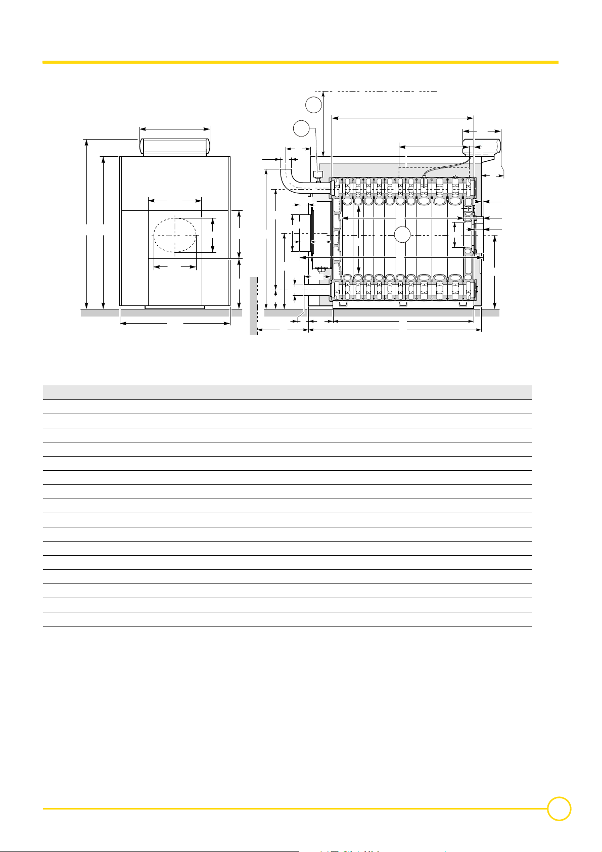
2.2 Main dimensions
P 520
1
A
755
616
1566
S
420
M000032
1172
Minimum height for sweeping = 850
370
496
543
Ø E
1080
C
200
815
2
D
K
*
*
Ø F
*
223
100
300
Ø E
MH
Burner centre line
741
718
T
3
U
B
LG
370
Flowrate detector
Boiler P 520 P 520-13 P 520-15 P 520-17 P 520-19 P 520-21 P 520-23 P 520-25
A (mm) 1563 1785 2007 2229 2491 2713 2935
B (mm) 1522 1744 1966 2188 2450 2672 2894
C (mm) 1488 1488 1488 1504 1504 1504 1504
D (mm) 256 188 210 257 209 231 253
Ø E (weld) (mm) 139.7 139.7 139.7 159 159 159 159
Ø F (mm) 350 400 400 400 * * *
G (mm) - 150 370 370 650 980 980
H (mm) 37 -31 -9 13 -35 -13 9
K** (mm) 49 -19 3 25 -23 -1 21
L (mm) 1955 2245 2445 2645 2955 3155 3355
M (mm) 275 324 321 299 324 324 303
P (mm) K 355 355 355 355 355 355 355
R (mm) K 175 175 175 175 175 175 175
S (mm) K 1760 1760 1760 1760 1760 1760 1760
T (mm) 1372 1594 1816 2038 2300 2522 2744
U (mm) 2021.5 2243.5 2465.5 2687.5 2949.5 3171.5 3393.5
P
50
R
17,5
240
140
791
* Plain plate, requires cutting. Maximum cut-out 500 x 700.
** Dimension representing the end of the 100 mm long chimney
connection.
G = Length required for clearing the water distributing tube.
Nota : with models P 520-21, P 520-23 and P 520-25, a plain plate
which must be cut out is supplied without the 100 mm chimney
connection.
02/04/08 - 300016859-001-A P 520
7
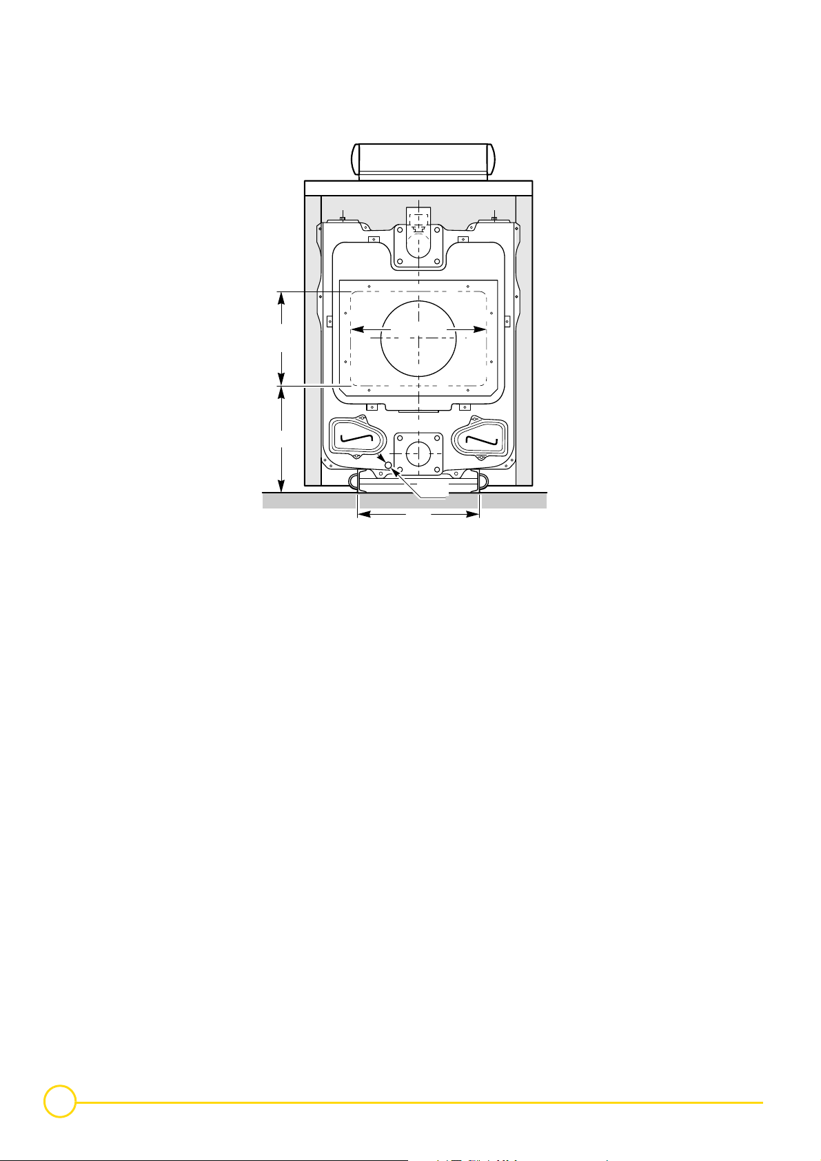
Main dimensions - Rear view P 520
500
Max
565
700 max
3/4"
610
M000158
8
P 520 02/04/08 - 300016859-001-A

3 Installing the boiler
3.1 Boiler location
For the assembly and because of their design, P 520 boilers require
no special base. Their closed furnace system means that the floor
need not have refractory properties. All you have to ensure is that the
floor can support the weight of the boiler when it is fitted for operation.
If the boiler location is not determined precisely, leave enough space
around the boiler to facilitate monitoring and maintenance
operations.
Boiler body *
Straight connection (not supplied) *
* 1) In order to facilitate subsequent work on the boiler(replacing the
water distributing tube etc.) use a flanged connection from the boiler
to the system, making sure you comply with minimum clearance
dimension D.
Angled connection (not supplied)
Air inlet
Air outlet
P 520 P 520-13 P 520-15 P 520-17 P 520-19 P 520-21 P 520-23 P 520-25
L 1955 2245 2445 2645 2955 3155 3355
M 275 324 321 299 324 324 303
C min. 300 436 656 656 936 1266 1266
D min. - 136 356 356 636 966 966
If A = 1.2 m (door opening side), A’ = 0.5 m
If A = 0.5 m, A’ = 1.2 m (door opening side) : adapt the dimensions
on the basis of the dimensions of the burner when the door is open.
B = 1.5 m : adapt the dimensions on the basis of the dimensions of
the burner.
02/04/08 - 300016859-001-A P 520
9
Loading...