


RE 27 AND RE 14
OPERATING
A N D
SERVICE MANUAL
C O R P O R A T I O N
1. WARRANTY EXPLANATION — PLEASE READ CAREFULLY
Rane offers a limited warranty, described in full on the Limited Warranty card included in the packing materials, which covers both parts and labor necessary to repair any defects in the manufacturing of your Rane product.
The warranty period is two (2) years, starting from either(i) the date of retail purchase, as noted on either the sales slip from an authorized Rane dealer or on the warranty registration card sent, in to the factory or, (ii) in the event no proof of purchase date is available, from the date of manufacture, which is coded on the rear of the chassis.
If you send in the registration card according to the instructions on the card, or retain your sales slip as proof of purchase, you will receive a full two (2) year warranty period from the date of purchase, regardless of the date of manufacture. If you do not send in the registration card (“I forgot.”), or you do not have a sales s1ip from an authorized Rane dealer (“My dog ate it.”), the warranty period will only extend two (2) years from the date of manufacture.
All registered warranties are tracked by serial number, not by owner. Once your Rane product is registered, it will be covered the full two years, regardless of any change in ownership.
Should you encounter any problems with your Rane product, be sure to contact either your local Rane dealer or the Rane factory before taking it anywhere for repairs. We will help you to identify and locate any specific malfunctions, possibly avoid needless shipment, or instruct you as to the speediest method for authorized repair.
If you must send your Rane product to the factory or a warranty station for repair, BE SURE TO INCLUDE THE FOLLOWING INFORMATION:
1.YOUR COMPLETE NAME AND RETURN SHIPPING ADDRESS (P.O. box numbers are NOT acceptable)
2.THE SERIAL NUMBER OF THE RANE PRODUCT IN FOR REPAIR
3.A COMPLETE DESCRIPTION OF ANY AND ALL PROBLEMS YOU ARE EXPERIENCING WITH THE PRODUCT.
Never ship the unit in any shipping carton other than the original or a replacement supplied by Rane. Ship only by a reputable carrier. Be sure to insure the package for the full replacement value. Rane cannot be held responsible for any damage incurred during shipping.
NOTICE REGARDING DAMAGES
THE RANE LIMITED WARRANTY COVERS ONLY THE COSTS IN LABOR AND MATERIALS TO REPAIR DEFECTS IN MATERIAL OR WORKMANSHIP OR, AT RANE’S OPTION, TO REPLACE DEFECTIVE PRODUCTS. CONSEQUENTIAL AND INCIDENTAL DAMAGES SUCH AS ECONOMIC LOSS OR INJURY TO PERSON OR PROPERTY, WHATEVER THE CAUSE, ARE EXCLUDED FROM COVERAGE. PLEASE REFER TO THE LIMITED WARRANTY CARD FOR A FULL DESCRIPTION OF THE LIMITS ON THE COVERAGE OF THE LIMITED WARRANTY.
If you need further assistance concerning the repair, installation or operation of your Rane product, please feel free to contact Rane galactic headquarters at:
Rane Corporation
10802 47th Avenue West
Mukilteo, WA 98275-5098
Phone: (425) 355-6000
FAX: (425) 347-7757
2

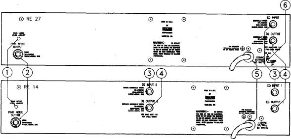
II. PANEL DESCRIPTIONS
RE 27 FRONT PANEL
RE 14 FRONT PANEL
1. EQ LEVEL CONTROL: This controls volume through the equalizer section and provides up to 6 dB overall gain. Turn this control down if the overload LED lights up.
2.BYPASS SWITCH: Push this button IN to bypass the equalizer and level control; the bypass LED will light whenever the bypass switch is engaged.
3.PINKNOISE SWITCH: Press this button IN toactivate the built-in pink noise generator. IMPORTANT: SWITCH THE PINK NOISE GENERATOR OFF WHEN NOT IN USE, TO PREVENT POSSIBLE NOISE BLEEDTHROUGH INTO PROGRAM MATERIAL
4.POWER SWITCH: You’ve probably figured this one out by now...
5.SIGNAL PRESENT INDICATOR: This green LED lights with any input above -20 dBm (.076 volts), even
in the bypass mode.
6.OVERLOAD INDICATOR: This red LED lights whenever the signal level through the equalizer section reaches 4 dB below clipping
7.ANALYZER DISPLAY LEDs: Each red LED lights up when response is too high in that band; green LEDs light when response is within ±3 dB or ±1 dB of the selected curve; yellow LEDs come on when response
is too low.
8.EQUALIZER SLIDERS: Calibrated in 3 dB increments, these sliders provide 12 dB of boost and 15 dB of cut at each of the ISO frequency centers.
9.CURVE SELECT SWITCH: The NORMAL position will yield a flat response when all LEDs are green. The HOUSE CURVE changes the response of the display such that the EQ sliders between 400 Hz and 1.6 kHz must be attenuated 3 dB to obtain green LED response. This reduction in midrange results in a warmer more desirable sound at lower sound pressure levels.
10.WINDOW SELECT SWITCH: In the ±3 dB position, the green LED in each band will be lit when
signals of that frequency are within 3 dB above or below the Normal or House curve, whichever is selected. In the ±1 dB mode, system response must be within 1 dB above or below the selected curve to light the green LEDs.
3
11. MICROPHONE INPUT JACK: PLUG ONLY THE RANE MICROPHONE INTO THIS JACK--THE DC POWER SUPPLY VOLTAGE SUPPLIED BY THIS JACK COULD BE DAMAGING TO ANY OTHER MICROPHONE When the mic is plugged in, the display responds to whatever the mic picks up; when the mic is unplugged, the jack automatically switches the display to monitor the output of the equalizer section (see Section IV-9).
12. RTA LEVEL CONTROL: Use this knob to adjust the microphone level (or line level when the microphone is unplugged) to properly drive the display. This control is accurately calibrated in dB-SPL; any display band whose LED is green has the sound pressure level indicated by this knob (only with the mic plugged in).
RE 27 REAR PANEL
RE 14 REAR PANEL
1. PINK NOISE LEVEL ADJUST: Use a 1/8" inch screwdriver to adjust the output from the Pink Noise generator from 0 to 1.2 volts (-4 dBm) to match the input level requirements of the mixer or other equipment driven by the generator.
2.PINK NOISE OUTPUT JACK: This is an unbalanced 1/4" jack which supplies Pink Noise to selected equipment
3.EQ INPUT JACK: This is an automatic balanced/unbalanced 1/4" input to the equalizer section. Use a mono 1/4" plug for unbalanced operation, or a stereo 1/4" plug wired as shown in the diagram below for balanced operation.
4.EQ OUTPUT JACK: This is the automatic unbalanced/floating output from the equalizer section. Use a mono%” plug for unbalanced operation, or a stereo 1/4" plug wired as shown in the diagram below for use with balanced equipment (Refer to Rane Note 102 for further information on Rane’s floating output system.)
5.AC LINE CORD: Plug this into a 120 VAC power outlet with grounding pin.
6.GROUND LIFT SWITCH: This switch provides the ability to separate chassis ground and signal ground. Normally, this switch should be in the LIFT position. If you are tempted to try movingthis switch with your power amplifiers turned on or turned up, DON’T BE. ALWAYS TURN YOUR AMPLlFIER LEVELS DOWN BEFORE CHANCING YOUR GROUNDS AROUND and then bring them up slowly.
4
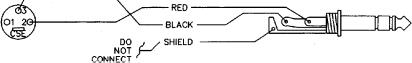
3 - P I N B A L A N C E D |
|
R A N E 1 / 4 " I N ( B A L ) |
|||||||||
|
|
|
|
|
|
|
|
|
|
|
|
|
|
|
|
|
|
|
|
|
|
|
|
|
|
|
|
|
|
|
|
|
|
|
|
|
|
|
|
|
|
|
|
|
|
|
|
|
|
|
|
|
|
|
|
|
|
|
|
|
|
|
|
|
|
|
|
|
|
|
|
See Rane Note 110 for other configurations.
III. INSTALLATION
This section contains several diagrams which plainly show many, but by no means all, of the ways to connect the RE 27 or RE 14 into a sound reinforcement or monitor system. Whatever your particular application, it is helpful to realize that the RE 27 or RE 14 is actuallytwo independent products in one: an equalizer with input(s) and output(s), and a realtime analyzer with mic input and pink noise output
Another thing to keep in mind is that the analyzer display will automatically monitor the output of the equalizer section whenever the microphone is unplugged from the front panel jack This feature is very useful in monitoring program material for feedback problems, resonances and the like.
Diagram III-1 : Main Speaker Equalization
Diagram III-2: Powered Mixer System Equalization
Diagram III-3: Stage Monitor Equalization Using Rane Microphone
Diagram III-4: Equalizing Specific Microphone/Speaker Combinations
5
 Loading...