


CP 52
CP 52
COMMERCIAL PROCESSOR
CONTENTS (in order of appearance)
Important Safety Instructions
CP 52 Manual
CP 52 Data Sheet
Rane Professional Install Products
Sound System Interconnection
Schematics
Warranty
Declaration of Conformity
14652
LEVEL
4k630 1.6k40 100 250
PROGRAM
SELECT
P
L2
L1
L3
OLSIGRMT
ON
LIMIT
10k
PRIORITYLIMIT
THRESHOLD
LIMIT
LEVEL LINE 1 LINE 2 LINE 3
OFF
ACTIVE
TRIM
INPUT
OL
LINEMIC
THRESHOLD
DETECT DUCKER
DEPTH
CP 52
POWER
ZONEPROGRAM INPUT LEVELSPAGING
LIMIT
THRESHOLD
PROCESSOR
COMMERCIAL
100
2
4
8
6
+60+30
12
•
6
•
•
•
6
12
0
+
+8
–3
+20–20
+16
+8
–3
+20–20
+16
100
2
4
8
6
100
2
4
8
6
100
2
4
8
6
100
2
4
8
6
100
2
4
8
6

108367
IMPORTANT SAFETY INSTRUCTIONS
For the continued safety of yourself and others we recommend that you read the following
safety and installation instructions. Keep this document in a safe location for future reference.
Please heed all warnings and follow all instructions.
Do not use this equipment in a location where it might become wet. Clean only with a damp
cloth.
is equipment may be installed in an industry standard equipment rack. We recommend that
all mounting holes be used, providing the best physical support. e equipment may be used as
a table top device, although stacking of the equipment is dangerous and not recommended.
Do not directly block any of the ventilation openings. If rackmounting, please provide adequate
ventilation. Equipment may be located directly above or below this unit, but note that some
equipment (like large power amplifiers) may cause an unacceptable amount of hum or may
generate too much heat and degrade the performance of this equipment.
Protect the power cord and plug from damage caused by being walked on or pinched. Protect
the line cord, where it exits the unit, from excessive strain. Only use attachments and acces-
sories specified by Rane.
Unplug this equipment during lightning storms or when unused for long periods of time.
Refer all servicing to qualified service personnel. Servicing is required when the apparatus has
been damaged in any way, such as power supply cord or plug damage, spilled liquid, fallen
objects into an opened chassis, exposure to rain or moisture, a dropped unit, or abnormal
operation.

Manual-1
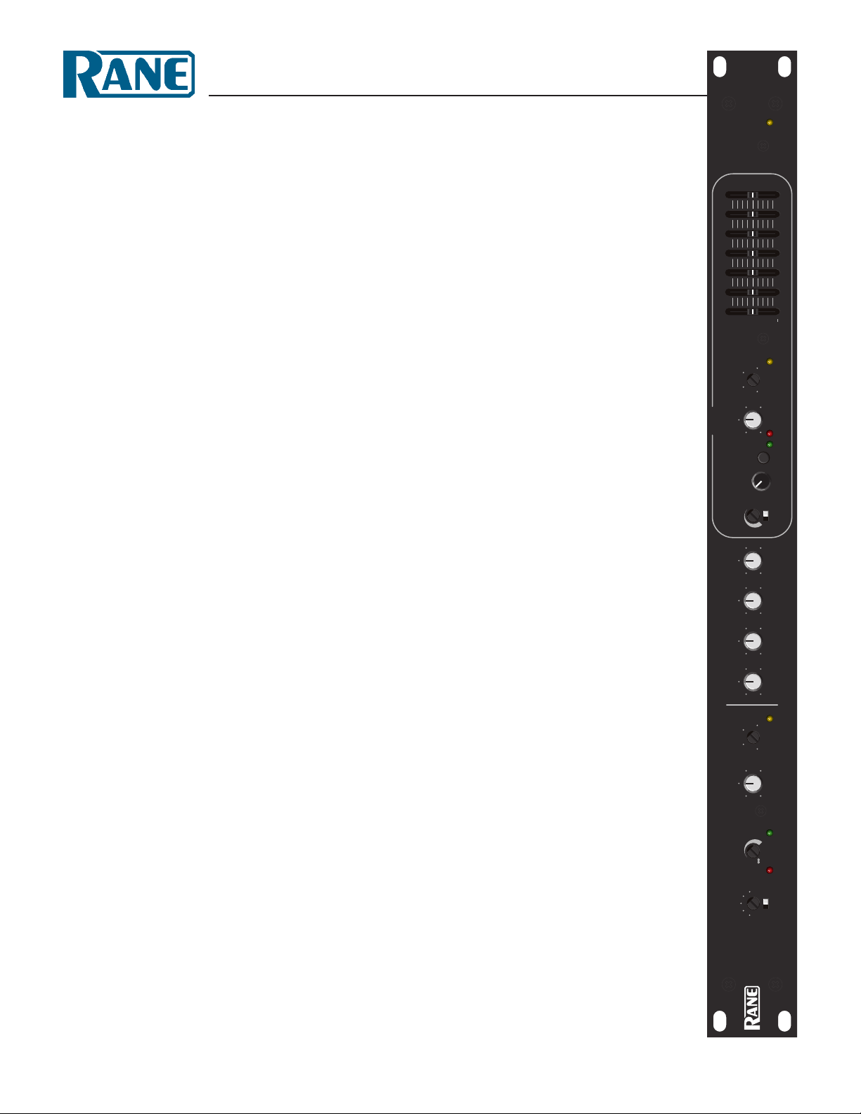
OPERATORS MANUAL CP 52
COM M ERCIAL PROCESSOR
Quick Start
If you were the type that cheated on school book reports
by just skimming through the reading assignments, then this
section is for you! It gives you not quite enough information to
really know what you’re doing. But, if you follow the recom-
mended set up procedure, you should get at least a “B.”
Keep the amplifiers and the CP 52 turned off until all con-
nections are made.
PAGE INPUT
Connect the PAGING INPUT to the Euroblock on the rear
panel. On the front, select the appropriate MIC or LINE switch
position. en set the gain with the INPUT TRIM control,
then set the PAGING DETECT THRESHOLD and finally the
PAGING LEVEL. MIC PHANTOM POWER, HIGH/LOW
CUT FILTER and PAGE LEVEL TRACKS ZONE LEVEL
switches are located on the rear panel.
PROGRAM INPUTS
Connect line level program sources to the RCA PROGRAM
INPUT jacks (LINE L1, L2, L3 & PRIORITY). If you have a
priority program, like a jukebox, connect it to the PRIORITY
Input. e rear panel PRIORITY switch turns priority override
ON or OFF. e Priority program is automatically selected when
signal is detected at its Input. Set the rear panel PROGRAM
DETECT THRESHOLD and RELEASE TIME as desired.
EXPAND OUTPUT
Wire the EXPAND OUTPUT Euroblock as required to a
mono feed delivering PAGE-only, PROGRAM-only or ZONE
(both) signal depending on the switch setting. is Output uses
a cross-coupled line driver and may be used balanced or unbal-
anced. Adjust the EXPAND OUTPUT LEVEL trim as desired.
WEAR PARTS: is product contains no wear parts.
LEVEL
4k630 1.6k40 100 250
PROGRAM
SELECT
P
L2
L1
L3
OLSIGRMT
ON
LIMIT
10k
PRIORITYLIMIT
THRESHOLD
LIMIT
LEVEL LINE 1 LINE 2 LINE 3
OFF
ACTIVE
TRIM
INPUT
OL
LINEMIC
THRESHOLD
DETECT DUCKER
DEPTH
CP 52
POWER
ZONEPROGRAM INPUT LEVELSPAGING
LIMIT
THRESHOLD
PROCESSOR
COMMERCIAL
100
2
4
8
6
+60+30
12
•
6
•
•
•
6
12
0
+
+8
–3
+20–20
+16
+8
–3
+20–20
+16
100
2
4
8
6
100
2
4
8
6
100
2
4
8
6
100
2
4
8
6
100
2
4
8
6
ZONE OUTPUT
e ZONE OUTPUT uses a cross-coupled line driver and
may be used balanced or unbalanced. Set the front panel LIMIT
THRESHOLD as required. Depress the rear panel MONO
switch for a mono Zone.
ZR 1 REMOTE
You may use one ZR 1 Remote (sold separately) with the CP
52. Wire it to the ZONE REMOTE Euroblock as indicated. If
a ZR 1 remote is not used, any simple switch closure to ground
will work for the D0 and D1 pins. ese pins are TTL compat-
ible (0 to 5 VDC). e logic is inverse Gray Code. Any ground
referenced 5 volt DC control may be used as the input to Vc. Do
not ground the Vr pin.
READ ME
e CP 52 is very versatile. While this makes a large number
of system applications possible, it also results in complexity. For
this reason, it is important to use an organized approach for setup
and calibration. A highly recommended setup procedure appears
on page Manual-5. Please follow it to encounter fewer problems
and reduce the need to increase our collective phone bills.
CAUTION: Never connect anything except an approved
Rane Power supply to the thing that looks like a red telephone
jack on the rear of the CP 52. is is an 18 VAC center tapped
power input. Consult the Rane factory for a replacement or
substitution.
 Loading...