


HAL
System Installation Guide
Halogen Software Version 6.2
HAL
System Installation Guide
IMPORTANT SAFETY INSTRUCTIONS
1.Read these instructions.
2.Keep these instructions.
3.Heed all warnings.
4.Follow all instructions.
5.Do not use this apparatus near water.
6.Clean only with a dry cloth.
7.Do not block any ventilation openings. Install in accordance with manufacturer’s instructions.
8.Do not install near any heat sources such as radiators, registers, stoves, or other apparatus (including amplifiers) that produce heat.
9.Do not defeat the safety purpose of the polarized or grounding-type plug. A polarized plug has two blades with one wider than the other. A grounding-type plug has two blades and a third grounding prong. The wide blade or third prong is provided for your safety. If the provided plug does not fit into your outlet, consult an electrician for replacement of the obsolete outlet.
10.Protect the power cord and plug from being walked on or pinched particularly at plugs, convenience receptacles, and the point where it exits from the apparatus.
11.Only use attachments and accessories specified by Rane.
12.Use only with the cart, stand, tripod, bracket, or table specified by the manufacturer, or sold with the apparatus. When a cart is used, use caution when moving the cart/apparatus combination to avoid injury from tip-over.
13.Unplug this apparatus during lightning storms or when unused for long periods of time.
14.Refer all servicing to qualified service personnel. Servicing is required when the apparatus has been damaged in any way, such as power supply cord or plug is damaged, liquid has been spilled or objects have fallen into the apparatus, the apparatus has been exposed to rain or moisture, does not operate normally, or has been dropped.
15.The plug on the power cord is the AC mains disconnect device and must remain readily operable. To completely disconnect this apparatus from the AC mains, disconnect the power supply cord plug from the AC receptacle.
16.This apparatus shall be connected to a mains socket outlet with a protective earthing connection.
17.When permanently connected, an all-pole mains switch with a contact separation of at least 3 mm in each pole shall be incorporated in the electrical installation of the building.
18.If rackmounting, provide adequate ventilation. Equipment may be located above or below this apparatus, but some equipment (like large power amplifiers) may cause an unacceptable amount of hum or may generate too much heat and degrade the performance of this apparatus.
19.This apparatus may be installed in an industry standard equipment rack. Use screws through all mounting holes to provide the best support.
WARNING: To reduce the risk of fire or electric shock, do not expose this apparatus to rain or moisture. Apparatus shall not be exposed to dripping or splashing and no objects filled with liquids, such as vases, shall be placed on the apparatus.
WARNING
CAUTION
RISK OF ELECTRIC SHOCK
DO NOT OPEN
ATTENTION: RISQUE DE CHOCS ELECTRIQUE - NE PAS OUVRIR
To reduce the risk of electrical shock, do not open the unit. No user serviceable parts inside. Refer servicing to qualified service personnel.
The symbols shown below are internationally accepted symbols that warn of potential hazards with electrical products.
This symbol indicates that a dangerous voltage constituting a risk of electric shock is present within this unit.
This symbol indicates that there are important operating and maintenance instructions in the literature accompanying this unit.
WARNING: This product may contain chemicals known to the State of California to cause cancer, or birth defects or other reproductive harm.
NOTE: This equipment has been tested and found to comply with the limits for a Class B digital device, pursuant to part 15 of the FCC Rules. These limits are designed to provide reasonable protection against harmful interference in a residential installation. This equipment generates, uses and can radiate radio frequency energy and, if not installed and used in accordance with the instructions, may cause harmful interference to radio communications. However, there is no guarantee that interference will not occur in a particular installation. If this equipment does cause harmful interference to radio or television reception, which can be determined by turning the equipment off and on, the user is encouraged to try to correct the interference by one or more of the following measures:
•Reorient or relocate the receiving antenna.
•Increase the separation between the equipment and receiver.
•Connect the equipment into an outlet on a circuit different from that to which the receiver is connected.
•Consult the dealer or an experienced radio/TV technician for help.
CAUTION: Changes or modifications not expressly approved by Rane Corporation could void the user's authority to operate the equipment.
CAN ICES-3 (B)/NMB-3(B)
Shielded CAT5e or better cables are required in order to comply with the FCC Rules part 15 limits for a Class B digital device.

HAL
System Installation Guide
INSTRUCTIONS DE SÉCURITÉ
1.Lisez ces instructions.
2.Gardez précieusement ces instructions.
3.Respectez les avertissements.
4.Suivez toutes les instructions.
5.Ne pas utiliser près d’une source d’eau.
6.Ne nettoyer qu’avec un chiffon doux.
7.N’obstruer aucune évacuation d’air. Effectuez l’installation en suivant les instructions du fabricant.
8.Ne pas disposer près d’une source de chaleur, c-à-d tout appareil produisant de la chaleur sans exception.
9.Ne pas modifier le cordon d’alimentation. Un cordon polarisé possède 2 lames, l’une plus large que l’autre. Un cordon avec tresse de masse possède 2 lames plus une 3è pour la terre. La lame large ou la tresse de masse assurent votre sécurité. Si le cordon fourni ne correspond pas à votre prise, contactez votre électricien.
10.Faites en sorte que le cordon ne soit pas piétiné, ni au niveau du fil, ni au niveau de ses broches, ni au niveau des connecteurs de vos appareils.
11.N’utilisez que des accessoires recommandés par Rane.
12.N’utilisez que les éléments de transport, stands, pieds ou tables spécifiés par le fabricant ou vendu avec l’appareil. Quand vous utlisez une valise de transport, prenez soin de vous déplacer avec cet équipement avec prudence afin d’éviter tout risque de blessure.
13.Débranchez cet appareil pendant un orage ou si vous ne l’utilisez pas pendant un certain temps.
14.Adressez-vous à du personnel qualifié pour tout service après vente. Celui-ci est nécessaire dans n’importe quel cas où l’appareil est abimé : si le cordon ou les fiches sont endommagés, si du liquide a été renversé ou si des objets sont tombés sur l’appareil, si celui-ci a été exposé à la pluie ou l’humidité, s’il ne fonctionne pas correctement ou est tombé.
15.La fiche du cordon d’alimentation sert à brancher le courant alternatif AC et doit absolument rester accessible. Pour déconnecter totalement l’appareil du secteur, débranchez le câble d’alimentation de la prise secteur.
16.Cet appareil doit être branché à une prise terre avec protection.
17.Quand il est branché de manière permanente, un disjoncteur tripolaire normalisé doit être incorporé dans l’installation électrique de l’immeuble.
18.En cas de montage en rack, laissez un espace suffisant pour la ventilation. Vous pouvez disposer d’autres appareils au-dessus ou en-dessous de celui-ci, mais certains (tels que de gros amplificateurs) peuvent provoquer un buzz ou générer trop de chaleur au risque d’endommager votre appareil et dégrader ses performances.
19.Cet appareil peut-être installé dans une baie standard ou un chassis normalisé pour un montage en rack. Visser chaque trou de chaque oreille de rack pour une meilleure fixation et sécurité.
ATTENTION: afin d’éviter tout risque de feu ou de choc électrique, gardez cet appareil éloigné de toute source d’humidité et d’éclaboussures quelles qu’elles soient. L’appareil doit également être éloigné de tout objet possédant du liquide (boisson en bouteilles, vases,…).
ATTENTION
CAUTION
RISK OF ELECTRIC SHOCK
DO NOT OPEN
ATTENTION: RISQUE DE CHOCS ELECTRIQUE - NE PAS OUVRIR
Afin d’éviter tout risque de choc électrique, ne pas ouvrir l’appareil. Aucune pièce ne peut être changée par l’utilisateur. Contactez un SAV qualifié pour toute intervention.
Les symboles ci-dessous sont reconnus internationalement comme prévenant tout risque électrique.
Ce symbole indique que cette unité utilise un voltage élevé constituant un risque de choc
électrique.
Ce symbole indique la présence d’instructions d’utilisation et de maintenance importantes dans le document fourni.
REMARQUE: Cet équipement a été testé et approuvé conforme aux limites pour un appareil numérique de classe B, conformément au chapitre 15 des règles de la FCC. Ces limites sont établis pour fournir une protection raisonnable contre tout risque d’interférences et peuvent provoquer une énergie de radiofréquence s'il n'est pas installé et utilisé conformément aux instructions, peut également provoquer des interférences aux niveaux des équipements de communication. Cependant, il n'existe aucune garantie que de telles interférences ne se produiront pas dans une installation particulière. Si cet équipement provoque des interférences en réception radio ou télévision, ceci peut être detecté en mettant l'équipement sous/hors tension, l'utilisateur est encouragé à essayer de corriger cette interférence par une ou plusieurs des mesures suivantes:
•Réorienter ou déplacer l'antenne de réception.
•Augmenter la distance entre l'équipement et le récepteur.
•Connecter l'équipement à une sortie sur un circuit différent de celui sur lequel le récepteur est branché.
•Consulter un revendeur ou un technicien radio / TV expérimenté.
ATTENTION: Les changements ou modifications non expressément approuvés par Rane Corporation peuvent annuler l'autorité de l'utilisateur à manipuler cet équipement et rendre ainsi nulles toutes les conditions de garantie.
CAN ICES-3 (B)/NMB-3(B)
Cartons et papier à recycler.
Un câble blindé de CAT5 ou de qualité équivalente voir meilleure sont nécessaires afin de se conformer à la réglementation de la FCC chapitre 15 sur les limites concernant les appareils numériques de classe B.

Table of Contents
CHAPTER 1: Getting Started |
1 |
The Installation Workflow |
1 |
Introduction to the HAL System |
4 |
System Requirements |
7 |
Minimum Requirements for Running Halogen |
7 |
Recommendations for Best Performance |
7 |
Administrative Rights Requirements |
8 |
Required Ports |
8 |
Required Processes |
9 |
Using the HAL System Documentation |
10 |
CHAPTER 2: Hardware Component Details |
13 |
Overview of HAL Devices |
13 |
Available HAL Models |
13 |
HAL Front and Rear Panels |
14 |
Discontinued HAL Models |
20 |
Remote Audio Devices |
23 |
How the shielded CAT 5e Cabling is Utilized |
23 |
RAD Grounding |
24 |
The Parts of a RAD |
26 |
PAGER1 RAD |
28 |
RAD16z |
29 |
AM1 and AM2 RADs |
32 |
RAD26 - One Room RAD |
33 |
RAD27 - USB Audio |
39 |
Discontinued RAD Models |
43 |
Digital Remote Devices |
43 |
DR Grounding |
44 |
Available Digital Remote Models |
45 |
iii

 HAL SYSTEM INSTALL GUIDE
Infrared Remote Devices |
62 |
IR2 Device |
62 |
Expansion Units |
63 |
HAL1x Expansion Units |
64 |
Discontinued EXP Models |
66 |
Shielded CAT 5e Cable Requirements |
67 |
Momentary and Latching Toggle Configuration |
68 |
CHAPTER 3: Installing Your HAL System |
72 |
Task 1: Install and Connect HAL |
72 |
Task 2: Configuring HAL |
74 |
Task 3: Pulling and Terminating shielded CAT 5e Cabling |
76 |
Task 4: Installing and Connecting HAL Expansion Units |
76 |
Task 5: Installing and Connecting RADs and DRs |
78 |
Task 6: Installing and Connecting Analog Devices |
83 |
Task 7: Verify and Troubleshoot Installation |
83 |
CHAPTER 4: Introduction to the Halogen Software |
87 |
Basic Structure |
87 |
Workspace Layout |
88 |
Installing and Starting the Halogen Software |
89 |
Uninstalling the Halogen Software |
91 |
Upgrading Halogen Software and HAL Firmware |
92 |
Generating Device Labels |
94 |
Generating Hardware Lists |
96 |
Locating a Device |
96 |
Swapping Hardware Devices |
98 |
CHAPTER 5: Troubleshooting Your HAL System Installation |
101 |
Troubleshooting the HAL Hardware |
101 |
Troubleshooting RAD Devices |
103 |
Troubleshooting DR Devices |
104 |
iv

Troubleshooting EXP Devices |
106 |
Troubleshooting the HAL Connection |
107 |
Using Meters to Troubleshoot |
111 |
Rane Technical Support |
111 |
Index |
112 |
Warranty Information |
116 |
Declaration of Conformity |
118 |
v

CHAPTER 1: Getting Started
Welcome to the world of HAL!
To help you get started with the installation of the HAL System, we have provided a simple breakdown of the key installation tasks—presented in the recommended order. If you are new to the HAL System, we recommend that (after reviewing this workflow) you spend a few moments reviewing the basics of the system before actually beginning the installation. We understand that your job is to get this system installed as quickly and efficiently as possible, but a slight detour to review the product details is well worth your time. See "Introduction to the HAL System" on page 4.
The Installation Workflow
There are seven key tasks involved in the installation of a HAL System. An overview of each task is listed below, along with page references to the specific details for each task. We recommend that you review this entire list to get a sense of the work flow, and then return to the first task to begin the actual installation process. Note that the order of some of these tasks can vary. See each task description for more details.
Task 1: Install and connect the HAL.
This task involves the physical attachment of the HAL hardware to your audio rack. You can perform this task offsite or on-site. Once installed, you then connect other devices to the HAL and, if necessary in your environment, connect the HAL to your Ethernet network. If you are installing onsite, you may want to pull and terminate the shielded CAT 5e cabling first (see "Task 3: Pulling and Terminating shielded CAT 5e Cabling" on page 76) so that the cables are ready to connect to the HAL. For details on installing the HAL, see "Task 1: Install and Connect HAL" on page 72.
Task 2: Configure the system.
Before the system can function properly, you must configure the hardware (the HAL, EXPs, RADs, and DRs) as well as the audio processing and path. You perform this configuration using the Halogen software that is shipped with the HAL hardware. (The software is also available on the Rane website at rane.com/hal.) You can configure the system by loading a configuration file that contains the appropriate hardware settings, audio flow, and processing; or you can create the configuration directly on a live device. We strongly recommend using a configuration file as a starting point!
In most cases, the audio designer will have already created this configuration file, which makes your installation job much easier. All you have to do is load the file into the HAL device. For the purposes of this guide, we have assumed this scenario—that the configuration file has already been created for you. If not—well, you’re going to need to do a little more reading. You can find additional information about configuration files in the Halogen Help System (accessed from the Halogen software) as well as in the HAL System Design Guide (available on your product DVD as well as on the Rane website).
NOTE: If the final configuration is to be completed later, but you merely want to install the equipment and make sure the system can send and receive audio, you can create a very simple configuration to accomplish this. See "Creating a Verification Configuration" on page 85 for more information.
Regardless if you’re creating a new configuration or simply loading a pre-defined configuration, you will need to install, start, and use the Halogen software.
1

 HAL SYSTEM INSTALL GUIDE
NOTE: Where this configuration task falls in the installation process is somewhat flexible. If you prefer, you can install and connect the RADs, DRs, and EXPs prior to loading the configuration file. There are advantages, however, in loading the configuration first. Whether or not the configuration is loaded, as long as the HAL is powered on and connected prior to installing the peripheral devices, you can determine immediately upon installing a RAD, DR, or EXP (by observing its status indicators) if it is functioning properly. But if the configuration is also in place, you can immediately determine if the EXP, RAD or DR model you just installed matches the model specified in the HAL configuration (if there’s a mismatch, the EXP's front panel LED's flash, the RAD’s LEDs flash red and the DR's LCD screen displays Configuration Mismatch). Also, if you have wireless access to the HAL, loading the configuration file early in the process makes it possible to then view the configuration from a laptop as you’re installing the RADs, DRs, and EXPs. If you do not have a configuration file and you plan to simply test that the installed equipment can successfully send and receive audio, disregard this recommendation. You will create a simple test configuration after you have installed all of the equipment.
Task 3: Pull and terminate the shielded CAT 5e cabling for the EXPs, RADs and DRs.
Each EXP, RAD and DR connects to the HAL via a shielded CAT 5e cable. We recommend pulling this cable prior to installing the RADs and DRs. Doing so makes it much easier to troubleshoot their installation. Note that each RAD and DR requires a home run. As noted in the previous task, if the shielded CAT 5e cables are installed and terminated, and the HAL is powered on and connected, you can verify if the RADs and DRs are working properly as soon as you connect them. For details on this task, see "Task 3: Pulling and Terminating shielded CAT 5e Cabling" on page 76.
Task 4: Install and connect HAL Expansion Units (if needed).
If your system requires one or more Expansion Units (EXPs), you should install and connect them to the HAL before beginning the installation of your Remote Audio Devices (RADs) and Digital Remotes (DRs). This task involves using shielded CAT 5e cable to connect each EXP in a daisy-chained fashion. That is, connecting the first EXP to HAL, connecting the second EXP to the first EXP, and so on. For details, see "Task 4: Installing and Connecting HAL Expansion Units" on page 76. It is important that you install the correct EXP model in each location and in the correct order in the daisy-chain. If you load the HAL configuration prior to installing the EXPs, you can view the status indicators to determine if you have installed the correct model. If the models do not match, the front panel LEDs on the EXP flash. You can also see this status in Halogen's Hardware Workspace.
The older HAL1 system used a FireWire based expansion bus. This bus allowed you to connect up to four EXP1 expansion units in a daisy-chained manner. For details see "Task 4 (legacy): Installing and Connecting HAL1 Expansion Units" on page 1.
Task 5: Install and connect the individual RADs and DRs.
This task involves the connection of the RADs and DRs to the shielded CAT 5e cable, followed by the physical installation of the RADs and DRs into the switchboxes in the wall. A key part of this task is to double-check that you are installing the correct RAD and DR models in each location. The wiring diagram should specify which RAD and DR models go in which locations. Also, if you load the HAL configuration prior to installing the RADs and DRs, you can view the RAD and DR status indicators to determine if you have installed the correct model. If the models do not match, the bottom four LED indicators on the RAD flash red, while the DR LCD screen displays Configuration Mismatch. In addition to verifying that you’ve installed the correct model, this task involves the verification that the RAD and DR hardware is communicating properly with the HAL. Again, the RAD and DR status indicators provide this information. For details, see "Task 5: Installing and Connecting RADs and DRs" on page 78.
2

CHAPTER 1: Getting Started
Task 6: Install and connect all analog devices.
This task needs little explanation and is here simply to suggest where in the workflow we recommend the installation and connection of analog devices. The HAL and some EXPs provide you with analog inputs and outputs. You know what to do with them!
Task 7: Verify connections, perform audio test, troubleshoot, and save the final configuration.
After installing the HAL, EXP device(s), RADs, DRs, connecting any other analog devices, and loading the configuration file, you need to verify that everything is working properly. See "Task 7: Verify and Troubleshoot Installation" on page 83.
NOTE: If you do not have a pre-defined configuration file but you want to verify that the hardware is working, you need to create a simple verification configuration. See "Creating a Verification Configuration" on page 85 for more information.
You’ll be happy to learn that Rane has taken much of the guesswork out of the verification process. Although you will review the status indicators on the HAL, EXPs, RADs, and DRs at the time you install these components, we recommend double-checking these indicators in the final verification task. There are three primary sources of information to help you quickly troubleshoot any problem:
1.RAD LEDs and DR LCD screens: By simply viewing the LEDs on the front of a RAD and the DR LCD screen, you can see immediately if the device is receiving power, if its data communications connection is working, and if its model matches the model configured for the port to which it is attached. With a RAD, you can also see if it's transmit (Tx) and receive (Rx) functionality is working, if it is actively receiving an audio signal, and if its audio signal is overloading.
2.HAL LEDs: LEDs on the HAL provide power and signal information for all the connected RADs and DRs as well as information about the Expansion Bus and Ethernet network (if applicable).
3.EXP LEDs: LEDs on the EXPs also provide power and signal information for all the connected RADs and DRs as well as information about the Expansion Bus.
4.Halogen messages: After the configuration file is loaded into the HAL, you can use Halogen to determine if you installed the appropriate RADs and DRs in each location or if a RAD or DR is configured incorrectly. The software displays color-coded messages telling you of any problems. The software also contains the configured audio flow, which you should examine if there are audio problems that cannot be traced to a hardware issue. It’s possible that something in the audio flow (in Halogen's Processing Workspace) was configured incorrectly.
When you have completed the installation, fully tested the system, and feel confident that the configuration is accurate, SAVE AND BACK UP THE CONFIGURATION FILE! If you or someone else inadvertently (or even deliberately) changes configuration settings on a live device and, as a result the system stops working, you will be very happy that you have a backup. For more details, see "Save the Final Configuration File" on page 85.
Now, on with the installation (after reviewing the basics of the system, of course!).
3
 HAL SYSTEM INSTALL GUIDE
Introduction to the HAL System
The HAL System, Rane's revolutionary new audio product, makes it possible for you to solve age-old audio issues with a simple click or two (or sometimes three). In designing this system, Rane's engineers have anticipated the needs of the installer, the designer, and the end user, resulting in an intuitive and relatively simple system to operate. You'll be amazed at how quickly you can accomplish tasks that used to take hours.
The HAL System includes both hardware and software components. This system introduction provides a broad overview of these components.
Hardware Components
The primary hardware component in a HAL System is the HAL host device. There is only one HAL device per system. HAL serves as the system's brain to which you connect other slave devices such as analog audio equipment, Remote Audio Devices (RADs), Digital Remotes (DRs), Expansion Units (EXPs), and more. Inside HAL is a DSP processor that manages the audio as well as a host processor that manages other aspects of the system.
The following graphic provides a visual of an entire HAL1x System:
4

CHAPTER 1: Getting Started
5
 HAL SYSTEM INSTALL GUIDE
Software Component
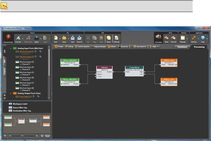
Included in the HAL System is a software application, called Halogen, that you use to configure and manage the entire system. Halogen contains two primary graphical workspaces, the Hardware Workspace and the Processing Workspace, in which you simply drag and drop hardware components and processing blocks to set up the audio system you want. You can work in online mode (connected to HAL) or offline mode (not connected to HAL or any other hardware). The ability to work in offline mode makes Halogen a powerful design tool available for use whether or not you have the hardware in hand. And not only can you design your system without having hardware in place, you can also test your system before you install the hardware! Now that's powerful!
NOTE: When working in online mode, changes made in the software are immediately implemented and saved to HAL (with the exception of DSP changes that require a system recompile).
Below is a sample of the Halogen Processing Workspace:
For more details on the Halogen software application, see "Introduction to the Halogen Software" on page 87.
6
CHAPTER 1: Getting Started
System Requirements
To use a HAL System, the following items are required:
•You must have access to a computer running Microsoft Windows 7 or greater. The computer must also have an Ethernet port, which you use to connect the computer to the HAL device (either directly or via an Ethernet network via a shielded CAT 5e cable). This connection is necessary for using the Halogen software to load configuration information into the device and also for monitoring detailed status information. Note that some status information is visible on the hardware itself.
•You must have administrative rights to install the Halogen software, but you do not need administrative rights to run the software.
•Most RADs require two, three, or four-gang standard switchboxes (for installation into a wall). A DR1 requires a one-gang switchbox, while a DR2 and DR3 require two-gang switchboxes. Switchboxes used for both RADs and DRs must have a minimum depth of 2 1/4" (57 mm).
Minimum Requirements for Running Halogen
•Microsoft Windows 7 or greater (32 or 64-bit)
•PC with 1.6 GHz Dual Core Processor (for example, Intel Core Duo, AMD Athlon X2)
•1 GB RAM
•2 GB available hard disk space
•Display Resolution: 1024x768, 24 bit color
•Ethernet adapter: 100baseT
•DVD Drive for installation from DVD (or can install from Rane website)
Recommendations for Best Performance
•Microsoft Windows 7 or greater (32 or 64-bit)
•PC with mid-level processor @ 2GHz multi-core or better (for example, Intel i3 or greater)
•2 GB RAM
•2 GB available hard disk space
•Display Resolution: 1920 x 1080, 24-bit color
•Display Adaptor: supports rendering tier 1 or 2 (see http://msdn.microsoft.com/en-us/library/ms742196.aspx) (i.e. directX 9.0 or greater)
•Ethernet adapter: Gigabit
7

 HAL SYSTEM INSTALL GUIDE
Administrative Rights Requirements
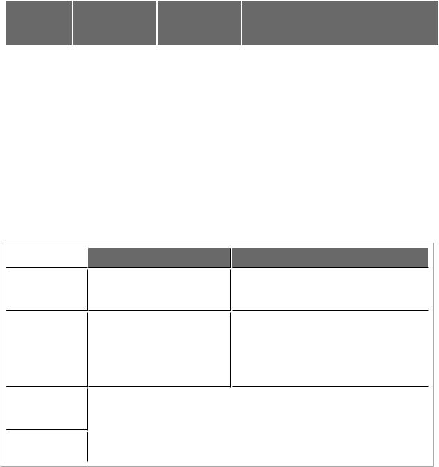
The following table outlines which Halogen tasks require administrative rights and which do not:
Requires administrative rights
•Installing Halogen
•Installing software updates to Halogen
•Manually starting or stopping the RaneLink II service
Does not require administrative rights
•Running and using Halogen
•Updating the HAL firmware
Required Ports
Communications between the PC (Halogen/RaneLink) and HAL
The PC and HAL exchange information using the following ports and protocols:
|
Local Port |
|
Remote Port |
|
Protocol |
|
Purpose |
|
|
|
|
|
|
||||
|
(PC) |
|
(HAL) |
|
|
|
||
|
|
|
|
|
|
|
||
|
|
|
|
|
|
|
|
|
|
Any |
|
|
TCP |
|
Secure file transfer |
|
|
|
22 |
|
|
|
||||
|
|
|
|
|
|
|
|
|
|
4992 |
|
Any |
|
TCP |
|
Meter control |
|
|
|
|
|
|
||||
|
|
|
|
|
|
|
|
|
|
4993 |
|
Any |
|
TCP |
|
Configuration |
|
|
|
|
|
|
||||
|
|
|
|
|
|
|
|
|
|
4994 |
|
Any |
|
UDP |
|
Discovery broadcast |
|
|
|
|
|
|
||||
|
|
|
|
|
|
|
|
|
|
4994 |
|
Any |
|
TCP |
|
RaneLink II1 |
|
|
|
|
|
|
||||
|
4995 |
|
Any |
|
TCP |
|
Meter data |
|
|
|
|
|
|
||||
|
|
|
|
|
|
|
|
|
|
|
|
|
|
|
|
|
|
These ports are listed from the PC's perspective to aid in configuring the PC's firewall so that RaneLink and Halogen can communicate with HAL hosts on your network.
HAL devices send occasional UDP broadcast messages. The RaneLink II service on the PC listens constantly for these messages and when it receives one, it does three things, if necessary:
•Sets up a temporary link-local IP address (in other words, the address is cleared when the computer reboots) on the appropriate network interface card (NIC).
•Adds an entry to the computer's network route table. RaneLink II maintains the list of HAL devices and it must be running for Halogen to communicate with a HAL, even if the HAL has been located by a manual search.
•Opens and maintains a TCP connection with HAL so that it can receive status updates.
1A service needed by Halogen to establish a connection with HAL.
8
CHAPTER 1: Getting Started
Additional Ethernet Communications
Halogen and HAL also use the following ports and protocols (independently of each other) to communicate with other systems such as a DHCP server or external control systems:
|
Local Port |
|
Remote Port |
|
Protocol |
|
Purpose |
|
|
|
|
|
|
||||
|
(PC or HAL) |
|
|
|
|
|||
|
|
|
|
|
|
|
|
|
|
|
|
|
|
|
|
|
|
|
68 |
|
|
UDP |
|
DHCP Client |
|
|
|
67 |
|
|
|
||||
|
|
|
|
|
|
|
|
|
|
4996 |
|
Any |
|
TCP |
|
External Control systems |
|
|
|
|
|
|
||||
|
|
|
|
|
|
|
|
|
|
80 (HAL) |
|
Any |
|
TCP |
|
Web Controls web server |
|
|
|
|
|
|
||||
|
8880 (PC) |
|
|
|
|
|
|
|
|
|
|
|
|
|
|
|
|
|
|
|
|
|
|
|
|
|
Required Processes
The following processes are required for working with the HAL System and for establishing a connection between Halogen and HAL.
Process
Halogen.exe‡
hal1.pcops.exe‡
python.exe‡
RaneLink II
 Purpose
Use to design your entire audio system and connect to your HAL device.
Simulates the behavior of a HAL when Halogen is not connected to a HAL. Allows for testing of such things as control links and presets, even when not connected to a HAL.
Location
C:\Program Files (x86)\Rane Corporation\Halogen\Halogen.exe
C:\Program Files (x86)\Rane Corporation\Halogen\hal1.pcops.exe
The server for web controls when |
|
C:\Program Files (x86)\Rane Cor- |
Halogen is not connected to a |
|
|
|
poration\Halogen\web\python.exe |
|
HAL. |
|
|
|
|
|
|
|
|
A service needed by Halogen to |
|
Services Control Panel |
|
||
establish a connection with HAL. |
|
|
|
|
|
‡If running 32-bit Windows, you can find Halogen.exe, hal1.pcops.exe, and python.exe in the "Program Files" directory.
9
 HAL SYSTEM INSTALL GUIDE
Using the HAL System Documentation
A variety of documentation is available to help you get started with and use your HAL System:
Halogen Help System
A comprehensive help system is installed with the Halogen software. It contains all the information you need to work with the system. There are several ways to access the Help System:
•Click the Help icon on the application toolbar:  Clicking the icon itself opens the Help System. Clicking the down arrow displays a list of options including such things as access to the Rane website, checking for updates to the Halogen software, and sending an email to Rane.
•Click the Help icon  that appears in the upper right corner of Halogen dialog boxes. Clicking this icon opens the Help topic related to the specific dialog box. From there you can access the entire Help System, if needed.
•Right-click on different elements in the user interface. A Help option appears in the context menu. Click this option to open the relevant Help topic. Pressing F1 when an area of the user interface has focus also displays its relevant Help topic.
•To search for information within the Help System, you can use the tabs on the Help Viewer's left pane to search the index (click the Index tab) or perform a full-text search (click the Search tab). You can also use the Quick search box in the Help System toolbar to search for text within the currently displayed topic: 
HAL System Design Guide
This guide is offered as a PDF file and contains a product overview, details about the HAL System's key features, and best practices for designing a HAL audio system. Note that the information in this guide is also available in the Halogen Help System. You can find this guide on the Rane website (http://rane.com/hal) as well as on the product DVD.
HAL System Installation Guide
This guide is offered as a PDF file and includes step-by-step instructions on installing the HAL hardware, loading a configuration, and testing the system. This information is also included in the Halogen Help System. You can find this guide on the Rane website (http://rane.com/hal) as well as on the product DVD.
AMX Control Systems Guide
This guide, includes an introduction to using external control systems with HAL. It also discusses an example HAL1 configuration and how to set up an AMX controller and touch panel to communicate with a Halogen/HAL Control Server. In addition, an appendix is included with reference information on the
HAL external control message protocol and how to use a telnet client to monitor and troubleshoot the operation of a control system at the message protocol level.
The guide is designed to be used in conjunction with the files found in the AMX Support Package. The contents of this support package include:
•AMXControlSystems_Guide.pdf - The AMX Guide pdf file
•ControlSystemSample.hal - Halogen configuration file intended for loading in Halogen or your HAL1x
•Rane_HAL.apw - NetLinx Studio program project file
•Main.axs - NetLinx program source file
•Rane_HAL_TP.TP4 - TPDesign4 touch panel project file
10
CHAPTER 1: Getting Started
The AMX Support Package is installed with the Halogen software and can be accessed from the Windows Start Menu under Halogen -> Guides. If you want to access the files directly they are available on the product DVD or from the Halogen install directory:
• C:\Program Files (x86)\Rane Corporation\Halogen\Guides\Support Packages\AMX directory
You can also download the most up-to-date version of this support package from the Rane website (http://rane.com/hal).
Crestron Control Systems Guide
This guide, includes an introduction to using external control systems with HAL. It also discusses an example HAL1x configuration and how to set up a Crestron controller and virtual touch panel to communicate with a Halogen/HAL Control Server. In addition, an appendix is included with reference information on the HAL external control message protocol and how to use a telnet client to monitor and troubleshoot the operation of a control system at the message protocol level.
The guide is designed to be used in conjunction with the files found in the Crestron Support Package. The contents of this support package include:
•CrestronControlSystems_Guide.pdf - The Crestron Guide pdf file
•ControlSystemSample.hal - Halogen configuration file intended for loading in Halogen or your HAL1x
•Rane_HAL.smw - SIMPL Windows program project file
•Rane_HAL_TP.vtp - VisionTools Pro-e touch panel project file
•Rane HAL Level Processor.usp - SIMPL+ user module source file
•Rane HAL Level Processor.ush - Compiled user module
The Crestron Support Package is installed with the Halogen software and can be accessed from the Windows Start Menu under Halogen -> Guides. If you want to access the files directly they are available on the product DVD or from the Halogen install directory:
• C:\Program Files (x86)\Rane Corporation\Halogen\Guides\Support Packages\Crestron directory
You can also download the most up-to-date version of this support package from the Rane website (http://rane.com/hal).
Stardraw Control Systems Guide
This guide, includes an introduction to using external control systems with HAL. It also discusses an example HAL1 configuration and an example Stardraw Control application and driver that communicates with a Halogen/HAL Control Server. In addition, an appendix is included with reference information on the
HAL external control message protocol and how to use a telnet client to monitor and troubleshoot the operation of a control system at the message protocol level.
The guide is designed to be used in conjunction with the files found in the Stardraw Control Support Package. The contents of this support package include:
•StardrawControlSystems_Guide.pdf - The Stardraw Control Guide pdf file
•ControlSystemSample.hal - Halogen configuration file intended for loading in Halogen or your HAL1x
•HAL1 Stardraw Example Project.s03 - Stardraw Control Project
•HAL1 Example Driver.cs - Stardraw HAL1 driver source code. This is part of the Stardraw Control Project but is included separately here for reference.
11
 HAL SYSTEM INSTALL GUIDE
The Stardraw Control Support Package is installed with the Halogen software and can be accessed from the Windows Start Menu under Halogen -> Guides. If you want to access the files directly they are available on the product DVD or from the Halogen install directory:
•C:\Program Files (x86)\Rane Corporation\Halogen\Guides\Support Packages\Stardraw Control directory
You can also download the most up-to-date version of this support package from the Rane website (http://rane.com/hal).
12

CHAPTER 2: Hardware Component Details
This chapter provides details about the HAL System hardware devices that you'll be installing.
Overview of HAL Devices
The HAL host device (which is referred to as HAL throughout this guide) is the brain that controls the entire HAL System. It can connect to a variety of other hardware (or slave devices) such as analog equipment, RADs, DRs, and EXPs. Inside the HAL hardware is a DSP audio processing engine and a host controller that controls DSP operations and manages control links, presets, and more. There is only one HAL device per system. You cannot connect one HAL to another.
NOTE FOR DRAG NET USERS: The DSP processing engine in the HAL1 device is four times more powerful than the RPM88, the HAL2 has twice the power as the RPM88, and the HAL3, HAL3s, and HAL4 have the same amount of DSP processing power as the RPM88.
Other Functionality
In addition to hosting other hardware devices and managing system operations, HAL also does the following:
•Provides power to connected RADs, and DRs
•Stores configuration settings and compatible firmware for itself and for each connected RAD, DR, and EXP
•Provides a connection to an Ethernet network (for control of HAL and the connected devices)
•Displays various status indicators (LEDs) providing information about the health of the system
Available HAL Models
The following HAL models are currently available. For the most current list of HAL models, see the Rane website.
HAL1x
The device connections that are possible on a HAL1x are as follows:
•4 Remote Audio Devices (RADs)
•8 Digital Remotes (DRs)—Can add up to 4 more by plugging them into the RAD ports
•1–32 Expansion Unit Devices (EXPs) (CAT 5e Expansion Bus)
•8 Mic/Line Inputs
•8 Line Outputs
•4 Logic Inputs
•2 Relay Outputs
HAL2
The device connections that are possible on a HAL2 are as follows:
•4 Remote Audio Devices (RADs)
•4 Digital Remotes (DRs)—Can add up to 4 more by plugging them into the RAD ports
13
 HAL SYSTEM INSTALL GUIDE
•4 IR Remotes
•8 Mic/Line Inputs
•8 Line Outputs
•1 AES3 Stereo Input
•1 AES3 Stereo Output
•4 Logic Inputs
•2 Relay Outputs
HAL3s
The device connections that are possible on a HAL3s are as follows:
•2 Remote Audio Devices (RADs)
•2 Digital Remotes (DRs)—Can add up to 2 more by plugging them into the RAD ports
•2 Mic/Line-Plus Inputs
•6 Line Outputs
•4 Logic Inputs
HAL4
The device connections that are possible on a HAL4 are as follows:
•1 Digital Remote (DR)
•2 Mic/Line-Plus Inputs
•2 Line Outputs
HAL Front and Rear Panels
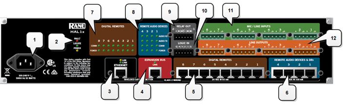
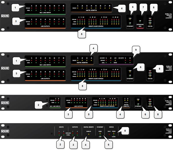
This section includes front and rear panel graphics for all current HAL models and descriptions for each major area on the panels.
Rear Panel Description
14
CHAPTER 2: Hardware Component Details
1.The Power IEC jack connects to AC line voltage, 100-240 VAC, 50/60 Hz.
2.Fault, Locate, and Power LEDs
The Fault LED (red) turns on when something in the hardware goes awry. The first step in troubleshooting the problem is to open the Halogen software and check the status of this HAL device.
The Locate LED flashes green when you place this HAL device in Locate Mode (via the Halogen software). The purpose of this Locate functionality is for verification, when working in the software, of the physical device you are configuring or viewing.
The Power LED lights when the HAL hardware is powered on.
3.Ethernet port and LAN and Link LEDs
Use this port to connect HAL to an Ethernet switch or directly to a computer.
15

 HAL SYSTEM INSTALL GUIDE
NOTE: This Ethernet port contains auto-MDIX functionality, which means that you can use either a standard Ethernet cable or a crossover cable to connect to a computer or Ethernet switch. The autoMDIX functionality takes care of coordinating the proper connection between the devices.
The Ethernet LAN LED flashes when HAL detects any Ethernet packets on the network. The Link LED indicates if the Ethernet network is connected. If HAL is connected to an Ethernet network but the Link LED is off, there is likely a problem with the connection.
4.Expansion Bus LED and CAT5e port
Use the Expansion Bus port to connect an Expansion Bus device (such as an EXP1x) to the HAL via a shielded CAT 5e cable. To attach additional Expansion Bus devices to your HAL System, use a shielded CAT 5e cable to connect each new device to the previous device—in a daisy chain style.
If lit, the Expansion Bus Link LED indicates that the Expansion Bus device is communicating properly with HAL. If an Expansion Bus device is properly connected to the port yet the status LED remains dark, there is likely a problem with the connection.
5.Digital Remote Device ports
Use these ports to connect each DR to the HAL via a standard shielded CAT 5e (or better) cable. You must use a shielded Ethernet cable for this connection. If you need more DR connections than the number of DR ports that the HAL provides, you can use a RAD port to connect a DR.
6.Remote Audio Device ports
Use these ports to connect each RAD to the HAL via a standard shielded CAT 5e (or better) cable. You must use a shielded Ethernet cable for this connection. If you need more RAD connections, you will need to connect an Expansion Unit with RAD ports (such as an EXP1) to your HAL device. You cannot connect a RAD to a DR port.
7.Digital Remote Device LEDs
Provides information about the health of the shielded CAT 5e connection between each DR and HAL. The numbers correspond to the DR ports in the lower area of the rear panel. The Comm LED (on the top row) lights solidly if the DR's data communications pair is working properly. The Power LED (on the bottom row) lights solidly if HAL is supplying adequate power to the DR port.
8.Remote Audio Device LEDs
Provides status information about the health of the shielded CAT 5e connection between each RAD and HAL. The numbers correspond to the RAD ports in the lower right corner of the rear panel. For example, the LEDs for number 1 provide information about the RAD connected on port 1. Each LED corresponds with one twisted pair within the shielded CAT 5e cable. If the twisted pair is functioning properly, the LED displays a solid green light when the HAL is programmed to expect the RAD model that is physically plugged in. When all cable pairs are working properly, but HAL is not yet programmed for the connected RAD model, all four LEDs flash red. Note that flashing red is a good thing: the cable’s good – just program HAL and you’re done.
•Audio Rx LED—lights solidly if the HAL receive pair is working properly.
•Audio Tx LED—lights solidly if the HAL transmit pair is working properly.
•Comm LED—lights solidly if the RAD's data communications pair is working properly.
•Power LED—lights solidly if HAL is supplying adequate power to the RAD port.
16
CHAPTER 2: Hardware Component Details
NOTE: The Remote Audio Device LEDs on the front panel differ from those on the rear panel. The front panel LEDs provide information about signal activity on each audio channel. See the "Overview of HAL Devices" on page 13 for more details.
TIP: You can use the Remote Audio Device LEDs on the rear panel and on the RAD to troubleshoot connection problems. See "Troubleshooting the HAL Hardware" on page 101 and "Troubleshooting RAD Devices" on page 103 for details.
9.Relay Out ports
Reed relay ports used to signal another device. A common implementation is to link a relay port to a Toggle control so that an end user can change its value. Also, the Halogen software contains a checkbox for each relay port, the value of which you can include in a preset or link to another control, making it possible to use a preset or control to turn the relay port on or off.
10.Logic In ports
Use these TTL 5-volt digital logic input ports to communicate to the HAL System via an external control device. You can configure each Logic In port to control a selector, toggle, or command within the HAL System. For example, you might use a Logic In port to select between two audio channels, or to mute the whole system.
11.Mic/Line Input ports
Use these ports to connect analog microphones or line input devices. Note that the Mic In ports support phantom power.
12.Line Output ports
Use these ports to connect analog line output devices, such as amplifiers or powered speakers.
13.AES3 ports
Use these ports to connect AES3 inputs and outputs to the HAL. The HAL2 supports one input port and one output port using standard XLR connectors. Each AES3 port provides two digital audio channels.
14.IR Remote ports
Use these ports to connect each IR Remote to the HAL via a standard shielded CAT 5e cable. You must use a standard Ethernet cable for this connection.
15.Mic/Line-Plus Input ports
Use these ports to connect microphone, balanced or unbalanced line input devices. When configured in Halogen for Condenser Mic, each input provides +48 V phantom power and 18 dB input gain. When Configured for Dynamic Mic, each input provides 30 dB input gain. When configured in Halogen for balanced, each input is +4 dBu balanced. When configured for unbalanced, each input is -10 dBV unbalanced, with left and right channels summed to a single mono input.
17
 HAL SYSTEM INSTALL GUIDE
Front Panel Description
1.Mic/Line Input LEDs
Provides status information about mic/line analog inputs connected to the HAL. The numbers correspond to the mic/line input ports on the rear panel.
These LEDs provide information on the following:
•Overload LED (red) – indicates that the mic/line input is experiencing a signal overload
•Signal LED (green) – indicates the presence of an audio signal on the mic/line input
2.Mic/Line-Plus Input LEDs
18

CHAPTER 2: Hardware Component Details
Provides status information about mic/line-plus analog inputs connected to the HAL. The numbers correspond to the mic/line-plus input ports on the rear panel.
These LEDs provide information on the following:
•Overload LED (red) – indicates that the mic/line-plus input is experiencing a signal overload
•Signal LED (green) – indicates the presence of an audio signal on the mic/line-plus input
3.Line Output LEDs
Provides information about HAL analog outputs. The numbers correspond to the line output ports on the rear panel.
These LEDs provide information on the following:
•Overload LED (red) – indicates that the line output is experiencing a signal overload
•Signal LED (green) – indicates the presence of an audio signal on the line output
4.Digital Remote LEDs
Indicates which Digital Remotes are enabled. Each numbered LED corresponds to the Digital Remote port with the same number. If a Digital Remote is connected on a port but its Enabled LED is off, there is likely a problem with the shielded CAT 5e connection or with the Digital Remote itself. If an Enabled LED is flashing, it indicates that the physical Digital Remote model does not match the Digital Remote model specified for this port in the HAL configuration.
5.Remote Audio Ports status indicators
Provides information about the RAD audio channels. The numbers at the top of the front panel correspond to the RAD ports on the back of the HAL. For example, the LEDs for number 1 provide information about the RAD connected on port 1.
Under each RAD number are LEDs for four audio channels, two input and two output. These four LEDs represent the maximum number of channels a RAD is capable of transporting. However, not all RAD models use all four channels. For example, the RAD1 model provides two microphone inputs, so only the two columns of indicators labeled IN would be active.
These LEDs provide information on the following:
•Overload LED (red)–indicates that the channel is experiencing a signal overload
•Signal LED (green)–indicates the presence of an audio signal on this channel
•Enabled LED (yellow)–indicates the availability of the associated audio channel. If a RAD is connected on this port and all Enabled lights are off, this indicates a problem with the shielded CAT 5e connection or with the RAD. If the Enabled LEDs are flashing, this indicates that the physical RAD model does not match the RAD model specified for this port in the HAL configuration.
6.The Ethernet Comm and Link LEDs
Provides status information about the HAL Ethernet connection.
•Comm LED (yellow) – flashes when HAL has been discovered by at least one PC running RaneLink II1, is solid when Halogen is exclusively connected to HAL, is off when HAL has yet to be discovered.
1A service needed by Halogen to establish a connection with HAL.
19

 HAL SYSTEM INSTALL GUIDE
•Link LED (green) – indicates if the Ethernet network is connected. If the HAL is connected to an Ethernet network but the Link LED is off, this indicates a problem with the connection.
7.The Expansion Bus LED
If lit, indicates that an Expansion Bus device is properly connected to the HAL. If an Expansion Bus device is properly connected to the port and powered on yet the status LED remains dark, there is likely a problem with the connection.
8.Fault, Locate, and Power LEDs
The Fault LED (red) turns on when something in the hardware goes awry. The first step in troubleshooting the problem is to open the Halogen software and check the status of this HAL device.
The Locate LED flashes green when you place this HAL device in Locate Mode (via the Halogen software). The purpose of this Locate functionality is for verification, when working in the software, of the physical device you are configuring or viewing.
The Power LED lights when the HAL hardware is powered on.
9.AES3 LEDs
Provides information about the AES3 digital audio channels. The numbers at the top of the front panel correspond to the AES channels on each port, two for the input port and two for the output port.
The Lock LED (yellow) indicates when the AES3 input port is locked to the attached AES3 output device.
Under each AES3 channel number are LEDs for that channel's audio, providing information on the following:
•Overload LED (red)–indicates that the channel is experiencing a signal overload
•Signal LED (green)–indicates the presence of an audio signal on this channel
Discontinued HAL Models
This section describes HAL models that are no longer in production. For the most current list of HAL models, see the Rane website. Data Sheets for discontinued models may also be downloaded from the Rane website.
The following devices are no longer available: HAL1, EXP1, and HAL3.
While Rane no longer produces the HAL3, Halogen software continues to provide support for this product, allowing customers to:
•Connect to HAL3 devices
•Open existing HAL3 configurations
•Build new HAL3 configurations
To build a new HAL configuration with a discontinued HAL, see Creating Configurations with Discontinued HAL devices below.
NOTE: Halogen no longer supports the HAL1 and EXP1 devices. If you would like to create or update a HAL1 configuration, use Halogen version 4.1.1 or earlier. To run multiple versions of Halogen on your PC, see http://blog.rane.com/2013/01/15/tip-running-multiple-versions-of-halogen-on-one-computer/.
20
CHAPTER 2: Hardware Component Details
HAL1 (Replaced by HAL1x)
The HAL1 uses a daisy-chain FireWire expansion bus able to support up to four EXP1 devices with a total of 32 output channels and 64 input channels. The maximum cable length for FireWire is 14.8 feet (4.5 meters).
For more information about the HAL1 FireWire expansion bus and EXP1 expansion unit, see "Overview of HAL1 Expansion Unit (Discontinued)" on page 1.
The HAL1x expansion bus uses a proprietary protocol running on a gigabit Ethernet physical layer with expansion devices connected in a daisy-chain configuration as before. The new expansion bus supports 512 output channels and 512 input channels with a maximum cable length of 330 feet (100 meters). There are currently four expansion devices for the HAL1x: EXP1x, EXP3x, EXP5x and EXP7x. The new bus is a significant improvement over the original FireWire bus.
For more information about the HAL1x expansion bus and expansion units, see "HAL1x Expansion Units" on page 64.
You cannot use the new (x) version expansion devices with the discontinued HAL1. The new HAL1x requires (x) version expansion devices.
The device connections that are possible on a HAL1 are as follows:
•4 Remote Audio Devices (RADs)
•8 Digital Remotes (DRs)—Can add up to 4 more by plugging them into the RAD ports
•1–4 Expansion Unit Devices (EXP1 devices) (FireWire Expansion Bus)
•8 Mic/Line Inputs
•8 Line Outputs
•4 Logic Inputs
•2 Relay Outputs
HAL3 (Replaced by HAL3s)
The original HAL3 provides two line/line+ inputs, one RAD port and three DR ports.
The new HAL3s provides two Mic/Line/Line+ inputs with available 48 volt phantom power, two RAD ports and two DR ports. The HAL3s also improves line input dynamic range by about 10 dB. The new features of the HAL3s open up new application spaces for the product, by supporting microphone input, two additional outputs and two additional inputs via the additional RAD port.
The device connections that are possible on a HAL3 are as follows:
•1 Remote Audio Device (RAD)
•3 Digital Remotes (DRs)—Can add up to 1 more by plugging it into the RAD port
•2 Line-Plus Inputs
•6 Line Outputs
•4 Logic Inputs
Creating Configurations with Discontinued HAL devices
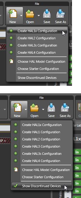
By default, Halogen only shows HALs currently in production in the New configuration drop down list.
21
 HAL SYSTEM INSTALL GUIDE
Click on Show Discontinued Devices to add discontinued HAL devices to the list as shown below:
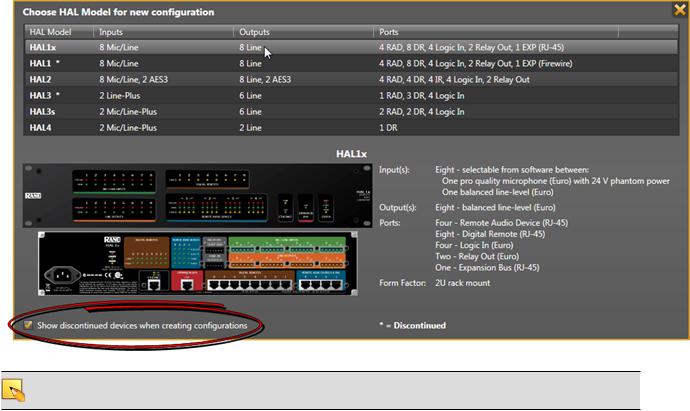
If you click on the New menu button, Halogen opens the HAL Model Picker dialog box. To display discontinued models, check the Show discontinued devices when creating configurations checkbox:
22
CHAPTER 2: Hardware Component Details
NOTE: In Halogen version 5.0.1 and later, you cannot create a new configuration for the unsupported HAL1 device.
Remote Audio Devices
The primary purpose of a Remote Audio Device (RAD) is to amplify, digitize, and transmit a digital audio signal via shielded CAT 5e cable to a HAL host device. RADs can also receive a digital signal from the HAL and then convert it to analog before sending it to its attached audio equipment. RADs are capable of transmitting and receiving up to four channels of digital audio (two in each direction). To better fit your needs, however, Rane offers various RAD models. Most RAD models are designed to fit in a standard U.S. two, three, or four gang switchbox.
The HAL System offers a variety of RAD models, each of which serves a unique purpose. For example, a RAD1 contains two microphone input channels. When you design an audio system, you choose the RAD models that are appropriate for your application. You must then provide configuration information to HAL so that it knows which RAD models to expect on each port and what information to send to each RAD. For more information, see "Available RAD Models" in the Halogen Help System. You can also read about the available RAD models on the Rane website.
How the shielded CAT 5e Cabling is Utilized
The shielded CAT 5e cable that connects the RAD to HAL also provides power to the RAD as well as a path for data communications. Data communications makes it possible to control the RAD’s configuration settings, view status information, and update a RAD’s firmware – all from the host HAL device. The following picture illustrates how the four twisted pairs within the shielded CAT 5e cable are utilized.
23

 HAL SYSTEM INSTALL GUIDE
•The orange pair is reserved for data communications between the RAD and HAL. Data communications is needed for such things as sending configuration information from HAL to the RAD, sending firmware updates from HAL to the RAD, and sending status information from the RAD to HAL.
NOTE: Configuration information for a specific RAD (for example, LED intensity, microphone sensitivity, and RAD and channel names) is stored in the HAL device, not in the RAD. This makes it easy to swap in a new RAD, if necessary, without losing configuration data.
•The green and blue pairs carry two channels each of balanced, differential, digital audio. Tx refers to audio that the RAD sends to the HAL. Rx refers to audio that the RAD receives from HAL.
•The brown pair provides 24 VDC power and ground for the RAD. This is (obviously) the wire you should check if it appears a RAD is not receiving power.
NOTE: Digital Remotes (discussed on page 43) use only the orange pair (for data communications) and the brown pair (for power).
RAD Grounding
Careful grounding of RADs is important for optimum performance. Except for the DR4, all RADs and DRs are powered from the +24 VDC & Ground twisted pair located within the shielded CAT 5e (or better) cable connecting them to the HAL system of multiprocessors. The exposed metal of all RADs and DRs is connected to the ground conductor inside the cable and to the cable shield when properly terminated. The shield conductor and the ground twist are in parallel and are connected together at both cable ends. Except for the RAD16z, this in turn connects the HAL/audio equipment rack grounding point and the metal (if used) junction box mounting the RADs and DRs.
NOTE: For some electrical systems (e.g., isolated grounding systems - sometimes called a single point or star ground) the grounding procedure outlined above may short two fingers of the building ground system. If this creates a problem, then use of non-conductive junction boxes, or insulating mounting methods are recommended (or very much required!).
NOTE: The RAD16z is grounded differently than the above. The RAD16z galvanicaly isolates its RJ-45 jack, cable shield and grounded twist, and the HAL/equipment room ground from its logic and audio I/O grounds. This means no special ground is needed. This provides 500-volts galvanic isolation as well as standard Eth-
24
 Loading...