


OPERATORS MANUAL |
AC 22 |
ACTIVE CROSSOVER
QUICK START
This is an automatic crossover! By automatic, we mean that the AC 22 is smart enough to know whether you want to run it as a two channel crossover, or as a single channel unit. It knows by the way the plugs are inserted how your system is to be configured. However, just because it is automatic, doesn’t mean that it will not automatically confuse you when you try to connect it in a bench test situation. NOTE: Labels above the controls refer to the unit being operated in the 2-
Way STEREO mode. Labels below the controls refer to the unit being operated in the 3-Way MONO mode.
Plugging a signal into the CHANNEL 1 INPUT and nothing into the CHANNEL 2 INPUT tells the unit that you are running a single channel system in Mono 3-Way mode, and therefore sets the unit up to be a single channel device. This can lead one to think that there are some dead channels in the unit when looking for output in places where there shouldn’t be any.
When operating the AC 22 as a Stereo 2-Way, follow the diagram on page Manual-3, reading the labels above the jacks and controls. To drive both channels with a mono signal, connect only to the CHANNEL 2 INPUT. This approach is the same as if you used a wye cable to both Inputs. This is very useful in situations where only one mix exists, but two independent channels of crossover are desired, normally used for separate amplification on each side of a stage. This is a good way to test both channels of the crossover when only one signal source exists.
The AC 22B is available as a fully balanced output version equipped with XLR connectors (for inputs and outputs) instead of the standard ¼" TRS jacks. If you are running balanced amplifiers from the AC 22 or are running crossover output cable lengths greater than 10 feet, we highly recommmend you purchase an AC 22B.
Never connect ANYTHING except an RS 1 or other approved Rane AC power supply to the thing that looks like a red telephone jack. This is an AC supply and requires some special attention if you do not have an operational power supply EXACTLY like the one that was supplied with your unit. Consult the Rane factory for replacement or substitution.
AC 22 CONNECTION
Balanced/Unbalanced Inputs
The ¼" Input jacks on the AC 22 are TRS (tip-ring- sleeve). We recommend connecting the AC 22 with a balanced cable from the balanced output of a mixer or equalizer.
If a balanced output is not available, and the cable run is less than ten feet (three meters), inserting an unbalanced ¼" TS (tip-sleeve) plug works in most situations.
Unbalanced Outputs
The ¼" Output jacks on the AC 22 are unbalanced TS (tip-sleeve). We recommend that cables to the amplifiers be no longer than ten feet (three meters).
See the “Sound System Interconnection” RaneNote included with this manual for more information on cabling and grounding requirements.
WEAR PARTS: This product contains no wear parts. |
Manual-1 |
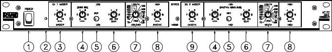
FRONT PANEL: STEREO 2-WAY CONFIGURATION
Observe the labels ABOVE the controls for Stereo operation.
POWER switch: Self-evident.
POWER indicator: When this yellow LED is lit the unit is ready to operate.
CH 1 MASTER LEVEL control: sets the overall level of Channel 1 without altering the relative settings of the HI and LOW outputs. Unity gain for all level controls is at “7”.
LOW frequency LEVEL control: sets the level of signal going to the Low Output in this Channel. Refer to alignment instructions on page Manual-11. In the MONO SUB mode the Channel 1 LEVEL control sets the Level of the mono subwoofer output; Channel 2's LEVEL control is inactive.
LOW frequency MUTE switch: When pressed to the in position, all signal is removed from the Low Output in this Channel. This eases tune-up procedures as described on page Manual-6. In the MONO SUB mode, the Channel 1 LOW MUTE switch Mutes the MONO SUB Output, Channel 2's Mute is inactive.
LOW frequency time DELAY control: adds from 0 to 2 ms of time Delay to the Low Output only. This allows a low frequency driver to be electronically phase-aligned with a high frequency driver whose diaphragm is situated behind the low frequency diaphragm. NOTE: Both DELAY controls are inactive in the MONO SUB mode. See instructions on page Manual-6.
Crossover frequency selector: This 41-detent selector determines the crossover frequency between Low and High frequency Outputs. The detents assure maximum accuracy and consistency between channels. Refer to page Manual-6 to determine the proper crossover frequency for your particular system.
HIGH frequency LEVEL control: sets the Level of signal going to the High Frequency Ouput in this Channel.
CH 2 MASTER LEVEL control: sets the overall Level of Channel 2 without altering relative settings of the HIGH and LOW Outputs.
Observe the labels ABOVE the inputs and outputs for Stereo operation.
Manual-2

REAR PANEL: STEREO 2-WAY INSTALLATION
CHANNEL 1 INPUT: This ¼" Input accepts either balanced TRS (tip-ring-sleeve) or unbalanced TS (tip-sleeve) plugs. Use this Input only if you are running two separate Channels. For true stereo operation, connect this Input to the left channel output of the mixer, equalizer or other signal source. If you are running two speaker systems from a single mono signal, use only the Channel 2 Input. See below.
CHANNEL 2 INPUT: This ¼" Input accepts either balanced TRS (tip-ring-sleeve) or unbalanced TS (tip-sleeve) plugs. For true stereo operation, connect this Input to the right channel output of the mixer, equalizer or other signal source. NOTE: Two separate speaker systems may be independently operated from a single mono source by using only the Channel 2 Input and omitting the Channel 1 Input. As long as nothing is plugged into the Channel 1 Input, Channel 2 will drive BOTH Channels of the AC 22 internally.
HIGH frequency OUTPUTS: These are ¼" TS (tip-sleeve) unbalanced Output jacks. Connect CHANNEL 1 HIGH OUT to the left channel input of the high frequency amp, and the CHANNEL 2 HIGH OUT to the right channel input of the high frequency amp.
LOW frequency OUTPUTS: Connect the CHANNEL 1 LOW OUT to the left channel input of the low frequency amp and the CHANNEL 2 LOW OUT to the right channel input of the low frequency amp. For Mono Subwoofer applications use CHANNEL 1 LOW OUT. CHANNEL 2 LOW OUT is disconnected in MONO SUB mode. (See below).
MONO SUB mode switch: This disconnects the CHANNEL 2 LOW OUT jack and sums it with CHANNEL 1 LOW OUT. The result is taken from the CHANNEL 1 LOW OUT jack.
Power input connector: USE ONLY AN RS 1, OR OTHER REMOTE AC POWER SUPPLY APPROVED BY RANE. This unit is supplied with a remote power supply suitable for connection to this input jack. Consult the factory for replacement or substitution. This unit’s power supply input is designed for an AC supply, delivering 18-24 volts, from a center-tapped transformer capable of supplying at least the current demanded by this product. Using any other type of supply may damage the unit and void the warranty.
Chassis ground point: A #6-32 screw is supplied for chassis grounding purposes. Always connect crossover chassis ground to amplifier chassis ground. See the CHASSIS GROUNDING note below.
CHASSIS GROUNDING
If after hooking up your system it exhibits excessive hum or buzzing, there is an incompatibility in the grounding configuration between units somewhere. Your mission, should you accept it, is to discover how your particular system wants to be grounded. Here are some things to try:
1.Try combinations of lifting grounds on units that are supplied with ground lift switches or links.
2.If your equipment is in a rack, verify that all chassis are tied to a good earth ground, either through the line cord grounding pin or the rack screws to another grounded chassis.
3.Units with outboard power supplies do not ground the chassis through the line cord. Make sure that these units are grounded either to another chassis which is earth grounded, or directly to the grounding screw on an AC outlet cover by means of a wire connected to a screw on the chassis with a star washer to guarantee proper contact.
Please refer to the RaneNote “Sound System Interconnection” (included with this manual) for further information.
Manual-3
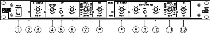
FRONT PANEL: MONO 3-WAY CONFIGURATION
Observe the labels BELOW the controls for Mono operation.
POWER switch: Self-evident.
POWER indicator: When this yellow LED is lit, the unit is ready to operate.
CH 1 MASTER LEVEL control: sets the overall level without altering the relative settings of the HIGH, MID and LOW Outputs. Unity gain for all LEVEL controls is at “7”. See the instructions on page Manual-11.
LOW frequency LEVEL control: sets the Level of signal going to the Low Output.
LOW frequency MUTE switch: When pressed to the in position, all signal is removed from the Low Output. This eases tune-up procedure, as described on page Manual-6.
LOW frequency time DELAY control: adds from 0 to 2 ms of time Delay to the Low Output only. This allows a low frequency driver to be electronically phase-aligned with a high frequency driver whose diaphragm is situated behind the low frequency diaphragm. Refer to page Manual-6 for alignment procedure.
CROSSOVER frequency selector: This 41-detent selector determines the Crossover Frequency between Low and Mid Outputs. The detents will assure maximum accuracy and consistency between Channels. Refer to page Manual-6 to determine proper Crossover Frequency for your particular system.
MID frequency LEVEL control: sets the Level of signal going to the Mid Output.
*NOTE: The Channel 1 HIGH LEVEL control and the Channel 2 MASTER LEVEL control are automatically bypassed internally when the AC 22 is connected as shown by the diagram on the facing page. Adjusting these controls will have no effect in the MONO mode.
MID frequency MUTE switch: When pressed to the in position, all signal is removed from the Mid Output.
MID frequency time DELAY control: adds from 0 to 2 ms of time Delay to the Mid Output only. This allows a mid frequency driver to be electronically phase-aligned with a high frequency driver whose diaphragm is situated behind the mid frequency diaphragm.
CROSSOVER frequency selector: sets the Crossover Frequency between the Mid and High Outputs.
HIGH frequency LEVEL control: sets the Level of signal going to the High Output.
Observe the labels BELOW the Inputs and Outputs for Mono operation.
Manual-4
 Loading...