


AC 23B

OPE RATORS MAN UAL
AC 23B
ACTIVE CROSSOVER
QUICK START
Labels above the controls refer to the unit being operated in the 2- or 3-Way Stereo mode. Labels below the
controls refer to the unit being operated in the 4- or 5-Way Mono mode.
The AC 23B is a fully balanced version of the popular AC 23 and is equipped with 3-pin (XLR-type) connectors instead
of the standard ¼" TRS jacks. A STEREO/MONO switch has been added to the AC 23B and should be set appropriately.
Switching jacks are not provided. All other specifications and operation are identical.
To operate the unit in Stereo 3-Way mode, be sure the rear panel switches are set for STEREO 3-WAY. Following the
labels above the controls and jacks in logical order, you will find CHANNEL 1 INPUT, LOW OUT, MID OUT, and HIGH
OUT, with the same for CHANNEL 2. The fact that the AC 23B is a multiple function unit means the outputs are switched
around in Mono mode. To use the unit as a Mono 5-Way, first check that the CHANNEL 1 and 2 switches are set to 3WAY, and the other switch is set to MONO. Connect the INPUT source to CHANNEL 1 only. Following the labels below
the jacks, look at SUB OUT, then look over at LOW OUT, now go back to MID OUT, then over to HI MID OUT and then
proceed to the HIGH OUT. An internal jumper determines 4 or 5-Way mode. Our apologies to 4-Way users: We must ship
the units in the 5-Way mode since normal Stereo 3-Way operation demands it: a fact not the least bit obvious, but nevertheless, a fact it remains. Pity. See page Manual-6 for Mono 4-Way configuration.
CAUTION: Never connect anything except an approved Rane Power supply to the thing that looks like a red telephone jack on the rear of the AC 23B. This is an 18 VAC center tapped power input. Consult the Rane factory for a
replacement or substitution.
AC 23B CONNECTION
In agreement with IEC and AES/ANSI standards, AC 23B
wiring convention is pin 2 Positive, pin 3 Negative (return),
pin 1 Signal ground (for unbalanced use), with the connector
case or shell tied to chassis ground.
Balanced Operation
Use only when driving from a true balanced source and
driving to a true balanced destination—either transformer
coupled or active drive. Connect the input to pins 2 and 3 with
pin 2 positive. Do not connect pin 1. Terminate the shield to
the case or shell. Connect the output to pins 2 and 3 with pin
2 positive. Do not connect pin 1. Connect the shield to the
case or shell.
WEAR PARTS: This product contains no wear parts.
Unbalanced Operation
Connect the input between pins 2 and 1 with pin 2
positive and pin 1 Signal ground. Short pin 3 to pin 1.
Terminate the shield to the case or shell. Connect the output
between pins 2 and 1 with pin 2 Positive. Leave pin 3 open—
do not short it to pin 1. Connect the shield to the case or shell.
Combination Operation
For combined balanced and unbalanced operation, use
whichever half of the above instructions apply for each end.
See the “Sound System Interconnection” RaneNote
included with this manual for more information on cabling
and grounding requirements.
Manual-1
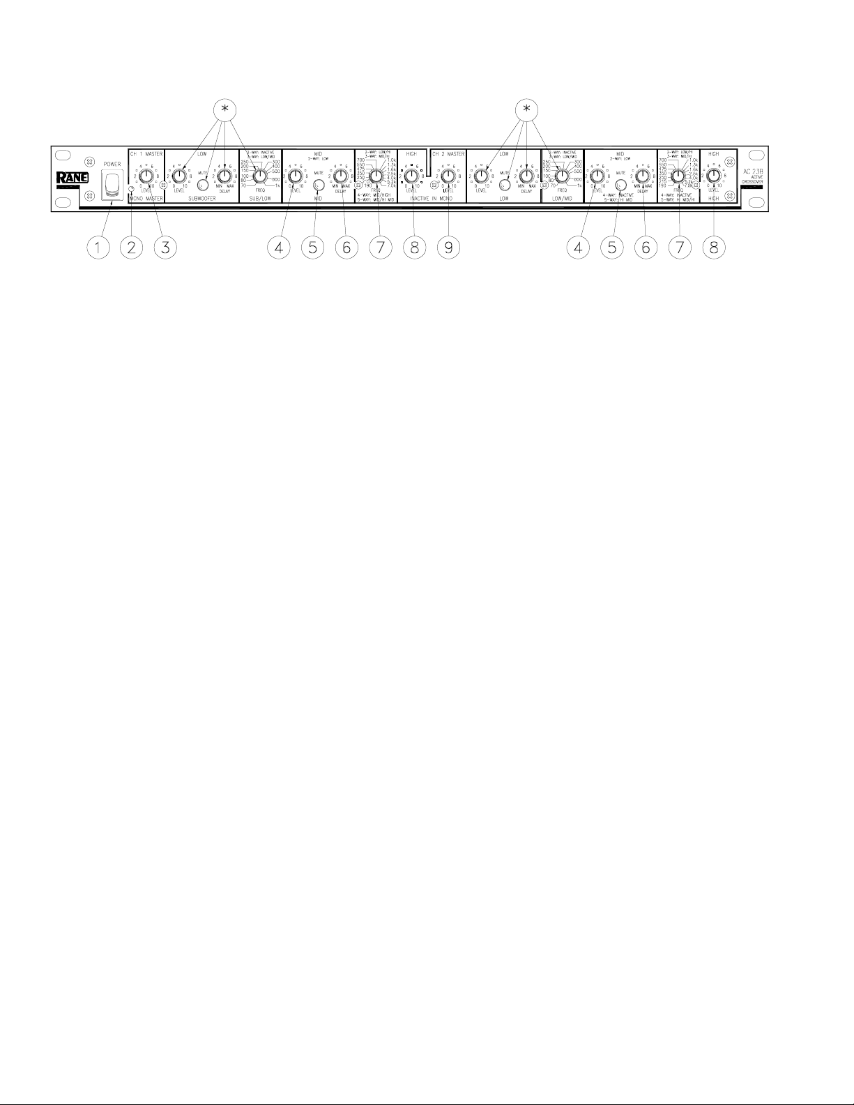
FRONT PANEL: STEREO 2-WAY CONFIGURATION
Observe the labels screened above the controls for stereo operation.
NOTE: In the 2-Way mode, the AC 23B crossover range is from 190 Hz to 7 kHz. The model AC 22 crossover
in stereo 2-Way mode is recommended when the crossover point needs to be outside of this range.
* Not used in 2-Channel 2-Way Mode
햲 POWER switch: Two guesses.
햳 POWER indicator: When this yellow LED is lit the unit is ready to operate.
햴 CHANNEL 1 MASTER LEVEL control: Sets the overall Level of Channel 1 without altering the relative settings of the
Low and High frequency Outputs. Unity gain for all level controls is at “7”.
햵 LOW LEVEL control: Sets the Level of signal going to the Low Frequency output in this channel. Refer to ‘Setting the
Output Level Controls’ on page Manual-15.
햶 LOW MUTE switch: When pressed to the in position, all signal is removed from the Low Frequency Output. This eases
tune-up procedures as described on pages Manual-11-16.
햷 LOW DELAY control: Adds from 0 to 2 ms of time Delay to the Low Frequency Output only. This allows a low fre-
quency driver to be electronically phase-aligned with a mid frequency driver whose diaphragm is situated behind the low
frequency diaphragm. Refer to ‘Time Delay Adjustment Procedure’ on page Manual-10.
햸 LOW/HIGH crossover frequency selector: This 41-detent selector sets the crossover frequency between the Low and
High frequency Outputs. Refer to ‘Selecting Crossover Frequencies’ on page Manual-10.
햹 HIGH LEVEL control: Sets the Level of signal going to the High frequency Output only.
햺 CHANNEL 2 MASTER LEVEL control: Sets the overall Level of Channel 2 without altering the relative settings of the
Low and High Outputs.
Manual-2

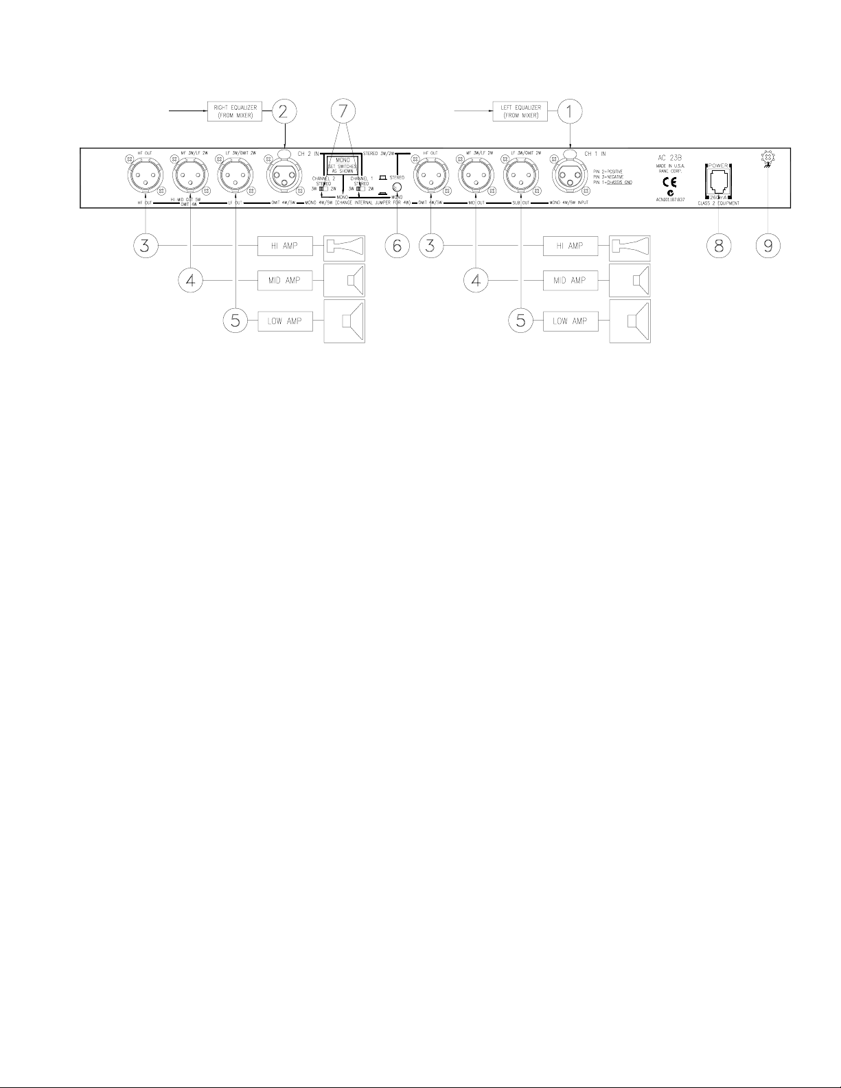
REAR PANEL: STEREO 2-WAY INSTALLATION
Observe the labels above the Inputs and Outputs for Stereo operation.
햲 CHANNEL 1 INPUT: Plug the left output of the mixer, equalizer or other signal source to this Input. See ‘AC 23B
Connection’ on page Manual-1 for wiring details.
햳 CHANNEL 2 INPUT: Plug the right output of the mixer, equalizer or other signal source to this Input..
햴 HIGH FREQUENCY OUTPUTS: Connect the CHANNEL 1 HIGH OUT to the left channel input of the high frequency
amp, and the CHANNEL 2 HIGH OUT to the right channel input of the high frequency amp.
햵 MID FREQUENCY OUTPUTS: Connect the CHANNEL 1 MID OUT to the left channel input of the low frequency
amplifier, and the CHANNEL 2 MID OUT to the right channel input of the low amplifier.
햶 2-WAY/3-WAY switch: Converts the outputs from 3-Way to 2-Way. This switch removes the Low frequency crossover
from the signal path. Low frequencies are now routed to the Mid frequency Output. Be sure to slide the switches to the
2-WAY position. Note: The Low frequency outputs are still active and may be used as additional subwoofer outputs.
햷 STEREO/MONO switch: Set this switch to the STEREO “out” position.
햸 POWER input connector: Use only a model RS 1 or other power supply approved by Rane. This unit is supplied with a
remote power supply suitable for connection to this input jack. This is not a telephone jack. The power requirements call for
an 18-24 VAC center-tapped transformer only. Using any other type of unapproved supply may damage the unit and void
the warranty. Two years parts and labor is worth safeguarding.
햹 Chassis ground point: A #6-32 screw is used for chassis grounding purposes. Always connect crossover chassis ground to
amplifier chassis ground. See ‘Chassis Grounding’ on page Manual-7 for details.
Manual-3
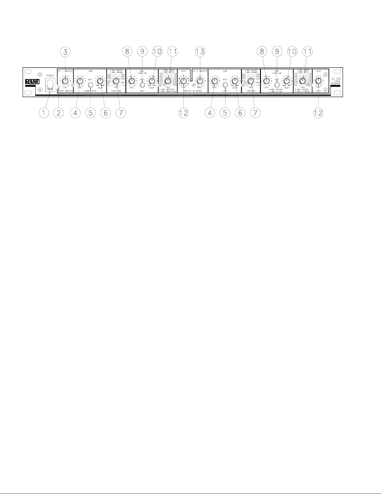
FRONT PANEL: STEREO 3-WAY CONFIGURATION
Observe the labels screened above the controls for stereo operation.
햲 POWER switch: Two guesses.
햳 POWER indicator: When this yellow LED is lit, the unit is ready to operate.
햴 CHANNEL 1 MASTER LEVEL control: Sets the overall Level of Channel 1 without altering the relative settings of the
Low/Mid/High frequency Outputs. Unity gain for all Level controls is at “7”.
햵 LOW FREQUENCY LEVEL control: Sets the Level of signal going to the Low frequency Output only in this Channel.
Refer to page Manual-15 for guidance with the Level control settings.
햶 LOW MUTE switch: When pressed to the in position, all signal is removed from the Low frequency Output. This eases
tune-up procedures as described on pages Manual-11-16.
햷 LOW DELAY control: Adds from 0 to 2 ms of time delay to the Low Frequency Output only. This allows a low frequency
driver to be electronically phase-aligned with a mid frequency driver whose diaphragm is situated behind the low frequency
diaphragm. Refer to page Manual-10.
햸 LOW/MID crossover frequecny selector: This 41-detent selector sets the crossover frequency between the Low and Mid
Outputs. Refer to page Manual-10.
햹 MID LEVEL control: Sets the Level of signal going to the Mid Output in this Channel only.
햺 MID MUTE switch: Removes all signal from the Mid Frequency Output when pressed to the in position.
햻 MID DELAY control: Adds from 0 to 2 ms of time Delay to the Mid Output only.
햽 MID/HIGH crossover frequency selector: Sets the crossover frequency between the Mid and High Outputs in this
Channel.
햾 HIGH LEVEL control: Sets the Level of signal going to the High Output only.
햿 CHANNEL 2 MASTER LEVEL control: Sets the overall Level of Channel 2 without altering the relative settings of the
Low/Mid/High Outputs.
Manual-4
REAR PANEL: STEREO 3-WAY INSTALLATION
Observe the labels above the Inputs and Outputs for Stereo operation.
햲 CHANNEL 1 INPUT: Plug the left output of the mixer, equalizer or other signal source to this Input. Refer to ‘AC 23B
Connection’ on page Manual-1 for wiring details.
햳 CHANNEL 2 INPUT: Plug the right output of the mixer, equalizer or other signal source to this Input.
햴 HIGH FREQUENCY OUTPUTS: Connect the CHANNEL 1 HIGH OUT to the left channel input of the high frequency
amp, and the CHANNEL 2 HIGH OUT to the right channel input of the high frequency amp.
햵 MID FREQUENCY OUTPUT: Connect the CHANNEL 1 MID OUT to the left channel of the mid frequency amp, and
the CHANNEL 2 MID OUT to the right channel of the mid frequency amp.
햶 LOW FREQUENCY OUTPUTS: Connect the CHANNEL 1 and 2 LOW OUTS to the left and right channels of the low
frequency amplifier, respectively.
햷 STEREO/MONO switch: Set this switch to the STEREO position.
햸 2-WAY/3-WAY switch: Converts the outputs from Stereo 3-Way to Stereo 2-Way. Be sure the switches are in the 3-WAY
position.
햹 POWER input connector: Use only a model RS 1 or other power supply approved by Rane. This unit is supplied with a
remote power supply suitable for connection to this input jack. This is not a telephone jack. The power requirements call for
an 18-24 VAC center-tapped transformer only. Using any other type of unapproved supply may damage the unit and void
the warranty. Two years parts and labor is worth safeguarding.
햺 Chassis ground point: A #6-32 screw is used for chassis grounding purposes. Always connect the crossover chassis to the
amplifier chassis. See ‘Chassis Grounding’ on page Manual-7 for details.
Manual-5

FRONT PANEL: MONO 4-WAY AND 5-WAY CONFIGURATION
Observe the labels screened below the controls for Mono operation.
햲 POWER switch: Two guesses.
햳 POWER indicator: When this yellow LED is lit, the unit is ready to operate.
햴 MASTER LEVEL control: Sets the overall Level of the entire unit in Mono mode, without changing relative settings of
the individual Sub/Low/Mid/High Outputs. Unity gain for all Level controls is “7”.
햵 SUBWOOFER LEVEL control: Sets the Level of signal going to the Sub Output. See page Manual-15.
햶 SUBWOOFER MUTE switch: Removes all signal from the Sub Output when pressed to the in position. This eases the
system tune-up procedure, as described on pages Manual-11-16.
햷 SUBWOOFER DELAY control: In Subwoofer applications this control has virtually no effect and will normally be set to
minimum (MIN). Refer to page Manual-10.
햸 SUB/LOW crossover frequency selector: This 41-detent selector sets the crossover frequency between the Subwoofer and
Low Outputs. Refer to page Manual-10 to determine the proper setting for your system.
햹 LOW LEVEL control: Sets the Level going to the Low frequency Output.
햺 LOW MUTE switch: Removes all signal from the Low Output when pressed in.
햻 LOW DELAY control: Adds from 0 to 2 ms of time Delay to the Low Frequency Output only. Refer to page Manual-10
for alignment procedure.
햽 LOW/MID crossover frequency selector: Sets the crossover frequency between the Low and Mid frequency Outputs.
햾 MID LEVEL control: Sets the Level of signal going to the Mid Output only.
햿 MID MUTE switch: Removes all signal from the Mid Output when pressed in.
헀 MID DELAY control: Adds from 0 to 2 ms of time Delay to the Mid frequency Output only.
헁 MID/HI MID crossover frequency selector: Sets the crossover frequency between the Mid and Hi Mid Outputs.
* NOTE: Both the CHANNEL 1 HIGH LEVEL control and CHANNEL 2 MASTER LEVEL control are automatically bypassed
when the AC 23B is switched to "MONO" on the back panel. Adjusting these controls has no effect in the Mono mode.
헂 Hl MID LEVEL control: This controls the Level of signal going to the Hi Mid Output only in 5-Way Mode. **NOTE TO
Manual-6
 Loading...