

Page 1
Quick Installation
For Bundles Featuring the QS206
H.264 Network DVR
Guide
16 Channel H.264 Compression DVR with
CIF Real-Time Recording
Page 2
PART 1 - PACKAGE CONTENTS
QS206 DVR
Color Cameras with Stands
Manual and
Software CD
manuals and
software
QS Serie s
QS408 • QS20 6
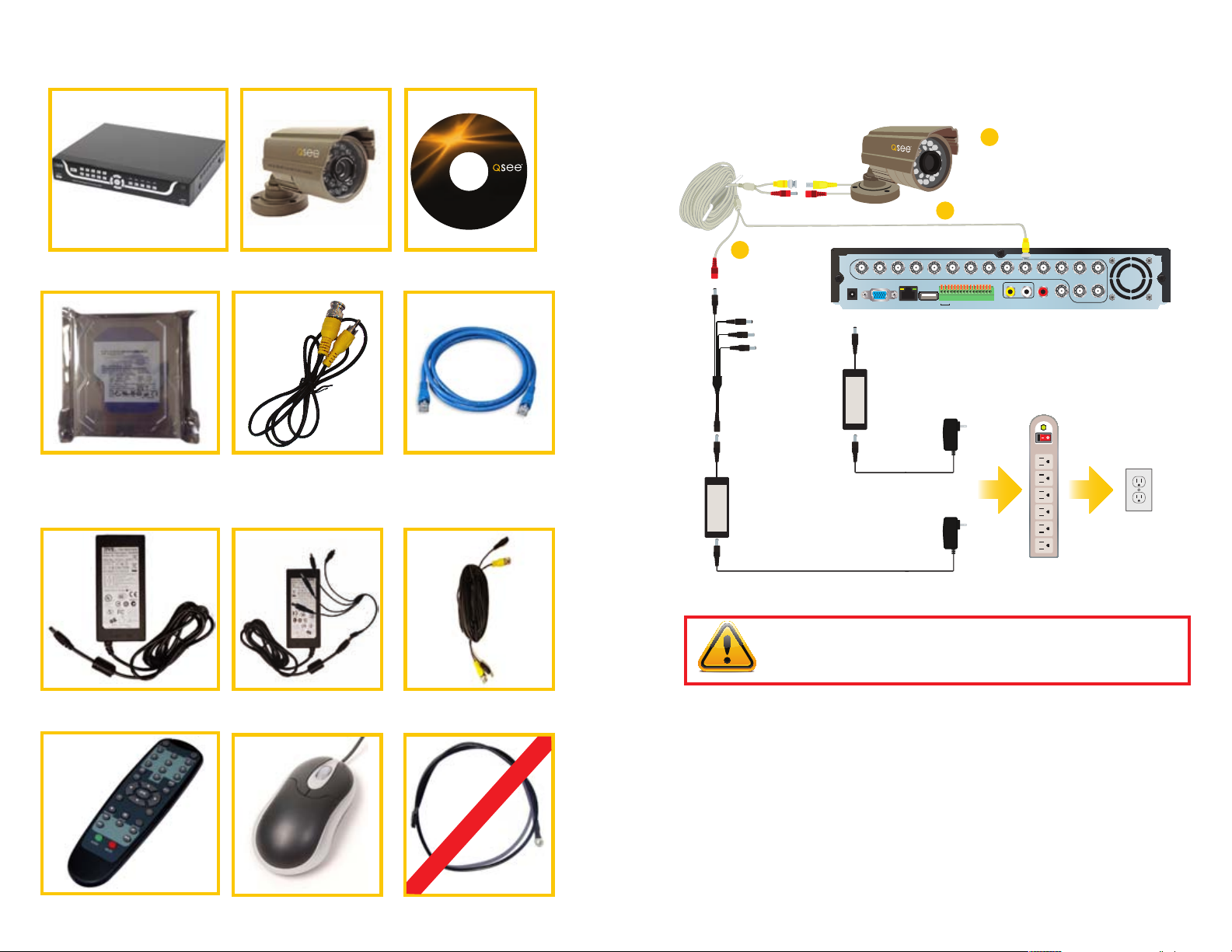
PART 2 - DVR CAMERA AND POWER CONNECTIONS
STEP 1: Connect the Cameras
to the Cables
1B
Connect both camera leads to the matching
1A
ends on the power/video cable.
Repeat for all cameras.
Attach the BNC connector on the power/video cable to a
Video In port on the DVR. Repeat for all cameras.
Pre-Installed
Hard Drive
Power Supply
for DVR
1 BNC(M) to RCA(M)
Adapter Cable
Power Supply and
4- or 8-Way Splitter
Ethernet
Cable
60-Foot
Power and Video Cable
(One per camera)
1C
Connect the remaining
connector to one of the
ends on the power
splitter. Repeat for all
cameras.
STEP 2:
Connect the single end
of the power splitter to
the included power supply.
STEP 4:
Connect both power supplies to
a surge protector.
2 3 4 5 6 7 8 9 10 11 12 13 14
1
DC +12V
VGA
IN
USB
RJ45
STEP 3:
Connect the other power supply to the DVR .
VIDEO IN
123
4
5
NO1
GND
COM1
COM2
ALM IN
AUDIO IN CVBS OUTAUDIO
NO2
GND
GND
GND
GND
+12V
485A-2
485A-1
485B-2
485B-1
16 15
OUT
STEP 5:
Connect thesurge protector
to an outlet.
IMPORTANT! It is STRONGLY recommended to use a surge protector that
is UL-1449 rated. Look for a clamping voltage of 330 or lower, a Joule rating
of at least 400 and a response time of 10 nanoseconds or less.
Remote Control
USB 2.0
Mouse
The appearance of contents may differ from images shown.
Grounding Cable
Not used in North America
Revised 6/29/11
Page 3
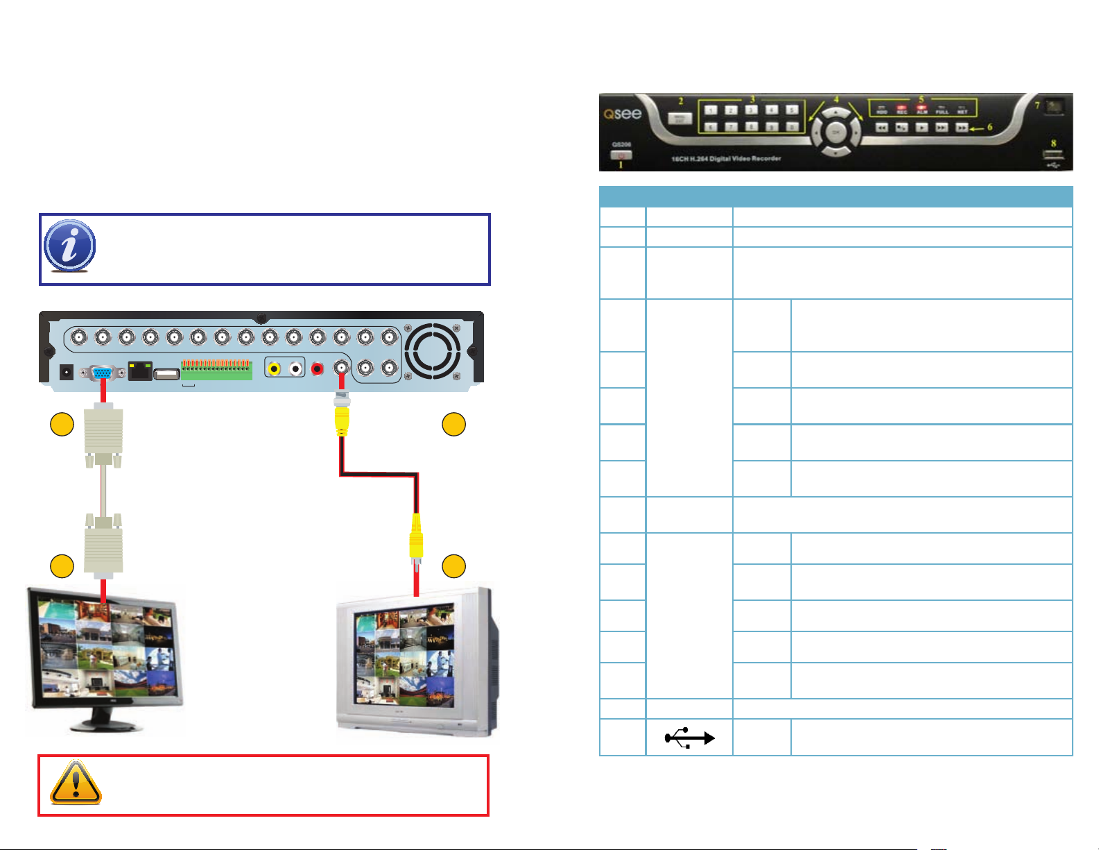
PART 3 - CONNECTING THE DVR TO YOUR DISPLAY PART 4 - DVR CONTROLS: FRONT PANEL
To Connect to a Computer Monitor:
1. Plug the VGA cable (not included) to the VGA port on the DVR.
2. Connect the other end of the VGA cable to the monitor.
To Connect to a TV:
3. Plug the BNC to RCA adapter cable into the Video Out port on the DVR.
4. Connect the other end of the RCA cable to the Video Input on the TV.
Item # Name/ Symbol Description
1 STANDBY Press to set the system in standby mode.
DC +12V
IN
1
2
NOTE! To switch back and forth between VGA and TV, use the
Mouse Scroll-Wheel: Forward-switch to VGA
Backward-switch to CVBS (TV).
VIDEO IN
1
2 3 4 5 6 7 8 9 10 11 12 13 14
123
4
VGA
NO1
NO2
GND
GND
GND
COM1
COM2
ALM IN
485A-2
485B-2
5
USB
RJ45
AUDIO IN CVBS OUTAUDIO
GND
GND
+12V
485A-1
485B-1
OUT
16 15
3
4
2 MENU/EXIT Press to open/close the main menu.
3 CHANNEL/
NUMBERS/
Press the number buttons to select a channel and view it fullscreen; press buttons 1-0 to input passwords and user IDs.
PLAYBACK
4 NAVIGATION/OKOK In menus, press to confirm selections; in PTZ mode,
press to change the navigation buttons to control a
connected PTZ camera (not included)
Press to move cursor up; in PTZ mode, press to pan
camera up.
Press to move cursor down; in PTZ mode, press to
pan camera down.
Press to move cursor left; in PTZ mode, press to pan
camera left.
Press to move cursor right; in PTZ mode, press to
pan camera right.
Increase reverse playback speed 1X, 2X, 4X.
Press to freeze playback to one frame, then press
again to advance frame-by-frame.
Press to start playback
Press to slow playback speed by 1/2, 1/4, 1/8.
|
Press to increase forward playback speed 1X, 2X,
4X.
5 LED
INDICATORS
6 DURING
PLAYBACK
PRESS:
▲
▼
◄
►
Shows status of hard drive, recording, alarm, HDD full and
network.
◄ ◄
n/►
►
► ►
► ►
7 IR SENSOR IR Receiver for remote control.
8 USB Connect a USB flash drive for data backup and
firmware upgrades
IMPORTANT! The default resolution of this DVR is 1024x768 pixels. Some
monitors smaller than 19” may have problems displaying this resolution.
Page 4

PART 5 - ACCESSING THE DVR’S MENUS
PART 7 - RECORDING
Choose MENU by right clicking on the mouse or by pushing the MENU button on the
DVR front panel or remote control.
The Main Menu offers the following Setup Features:
SEARCH: Search for recorded video on
the system.
RECORD: Enable recording & audio, set
resolution & quality, recording mode and
file size.
HDD: Display hard drive status and format
the internal hard drive of the system.
BASIC: Open the Basic Setup Menu,
which lets you set the system language,
date and time, Device IDs and passwords,
and configure audio and video settings.
ADVANCE: Opens the Advanced Setup Menu, which lets you view system info, configure
alarm, PTZ, mobile, and network settings.
EXIT: Closes the Main Menu.
PART 6 - SETTING UP CAMERAS FOR VIEWING AND
RECORDING
From the Main menu, select BASIC then
DISPLAY. Here you can setup the name
display (up to 8 characters) and position
of each channel (cameras). Select COLOR
SETUP to adjust the image brightness, saturation, contrast and hue settings for each
channel (camera). You can also choose
whether each channel can be previewed in
LIVE MODE and/or RECORDING MODE.
This System offers 3 modes for recording:
1. Manual 2. Time Schedule 3. Motion Detection.
From the main menu, select RECORD to
enter into the Record Setup menu (shown
on the left).
SWITCH: “ON” enables video to record
from the respective camera. If the channel
is set to “OFF”, video from that channel will
not record.
BITRATE: Select HIGH, MEDIUM, or
LOW
FRAMERATE: Select 1 to 30 frames per
second
Using higher Bitrate settings results in better video quality, but takes up more space on the
hard drive. Choosing lower settings result in lower video quality, but takes up less space
on the hard drive.
AUDIO: If audio is ENABLED sound will be recorded with the video from the channels,
and will have audio output in playback mode. If audio is DISABLED, sound will not record,
and there will be no audio output in playback mode (Audio cameras or a microphone is
required to record the sound).
REC MODE: select POWER UP or TIMER RECORD. If you select POWER UP, the system
will record continuously (Normal Recording) when the system is powered on. If you select
TIMER RECORD, you have to set a recording schedule on the system.
REC SIZE: Choose the time length of all recorded files: 15, 30, 45, 60 min. (Max = 60 min)
NEXT PAGE: Takes you to the settings for cameras 5 through 8, 9 through 12 and 13-
16 in sequence.
Page 5

The Schedule Grid shows the days of
the week and hours 0~23. You can set
Alarm Recording (Red), General (Normal)
Recording (Green), or No Recording (Blue)
to each time block of each day.
Manual Recording:
From the Record Setup screen set the Rec Mode to “ALWAYS”. Your DVR will continuously record and separate files will be created with the Pack Time intervals you selected.
Time Schedule Recording:
From the Record Setup screen, set the Rec Mode to TIMER RECORD and click “SCHEDULE”. This will display the Schedule menu (see image above). Select the channels (cameras) that you wish to record on a schedule. The options are: CH-1 through CH-16, and
ALL. Click on the green GENERAL option box then click on the boxes for the days and
times that you want to record using this option on the timeline. You can use the [From
– To] pull-down menus and COPY button to copy settings from one day to another day,
or all days. Your DVR will record on it’s Time Schedule, and separate files with the Pack
Time Interval you selected. Click APPLY to activate your customized schedule, and then
reboot the DVR.
Motion Detection Recording:
From the Record Setup screen, set the Rec Mode to TIMER RECORD and click “SCHEDULE”. This will display the Schedule menu (See picture above). The options are: CH-1
through CH-8, and ALL. Click on the red ALARM option box then click on the boxes for
the days and times that you want to record using this option on the timeline. You can
use the [From – To] pull-down menus and COPY button to copy settings from one day
to another day, or all days. Your DVR will record on Motion Detection. Click APPLY to
activate your customized schedule, and then go to the Avanced option (red box in first
below picture) and select the Motion Option (red box in second picture below), which will
display the Motion Detect Box.
The Motion Detection Menu has 3 sections, including Channel Status, Sensitivity
and Motion Area.
Status: This option allows you to enable
motion detection on any channel.
Sensitivity: This option allows you to set
sensitivity level of motion detection from 1
to 8, with 8 being the highest.
MD Area: Allows you to set the area
of the camera view that you want to be
sensitive to motion.
EMAIL: ON-Open MD alarm to trigger email, OFF-Close MD alarm to trigger email.
NOTE: Email alarm can be assigned to each channel
Next, click on the MD AREA SETUP but- click on the MD AREA SETUP but-click on the MD AREA SETUP button, which will display the picture on the
left. This option allows you to select the
area you want to be sensitive to motion.
You can set this area by using the mouse
or REV, FWD, and SEL keys on the front
panel. Once you have set the area, right
click with the mouse or push the ESC key
key to save the setting. After you have set
all of the cameras, click on the Apply button to save the settings.
Page 6

PART 8 - VIDEO SEARCH AND PLAYBACK
Video Search:
From the Main Menu select SEARCH to
display the Video Search Menu shown to
the right. If you input a specific date and
click Search, you will find all the recordings
for that day. When you select an item, you
will playback the recordings in 16 channel
mode; or, click [File list] button to display
File list interface, where you can playback
or backup the file you selected. See File
List heading below.
In the playback window you can play video Forward at 2x, 4x, and 8x speeds, Slow
play at 1/2x, 1/4x, and 1/8x, or normal play, pause and play frame by frame using the
playback control bar, and adjust volume by clicking or sliding tune control bar. When
playback has finished, system will return to previous menu.
File List:
On the Search Menu click the Search button then click File list to display the sub-menu
shown in the picture below.
This option will allow you to view all of the available files by channel and type (all,
normal, or alarm).
You can click on a file to playback the file.
PART 9 - VIDEO BACKUP
Attach a USB flash drive or USB hard drive to the USB backup port and follow the instructions in Part 9 to go to the File List in the Search menu.
If you want to backup a single recorded file from the file list, from the File List dialog box
pictured above, select the file you wish to back up by placing a check mark in the BAK
box and hit the [BACKUP] button on bottom of the screen. You will then receive a pop up
screen as illustrated below showing you the progression of your backup. Once backup is
complete, you will then receive a pop up message informing you that you have backed up
your files successfully. Note that all files will be in an H264 format that can be converted
to AVI using the playback software that comes with the DVR or through the remote viewer
program. Once converted, you can then view these files through any program that supports an AVI format.
Use the buttons on the side panel to
navigate the file list:
FIRST: Jump to the first page of the
list
PRE: Turn to the previous page
NEXT: Turn to the next page
LAST: Jump to the last page of the
list
ALL: Select all files
OTHER: Clear all files
BACKUP: After selecting a file(s), click
to begin copying the data to a USB
flash drive (not included)
Page 7

QUESTIONS OR COMMENTS? CONTACT US
MAILING ADDRESS
Q-See Products
Digital Peripheral Solutions, Inc.
8015 E. Crystal Drive
Anaheim, CA 92807
FAX
714-998-3509
WEBSITE
www.Q-See.com
PRODUCT SUPPORT, DOWNLOADS,
FIRMWARE UPDATES
& MANUALS
www.Q-See.com
CUSTOMER SUPPORT
Live Chat at www.Q-See.com (M-F, 9-5 PST)
Email: support@dpsi-usa.com
Phone: 877-998-3440 (M-F, 9-5 PST)
 Loading...