

Page 1

Remote Monitoring
Setup Guide
QC SERIES NVR MODELS
Apple Macintosh
Computer
iPhone
Setup Guide for Remote Internet and Smartphone Monitoring,
MyQ-See DDNS, and Email Notification
Android
BlackBerry*
* Select Models
PC with Windows
Operating System
1
Page 2
Thank You for Choosing a Q-See Product!
This manual was accurate at the time it was completed. However, because of our ongoing
THANK YOU FOR PURCHASING THIS Q-SEE PRODUCT.
effort to constantly improve our products, along with smartphone and router manufacturers
EVERY EFFORT HAS BEEN MADE TO MAKE THIS NVR SIMPLE TO ASSEMBLE AND USE. HOWEVER, IF
adding and changing features on their products, it is possible that some functions may
YOU SHOULD RUN INTO ANY DIFFICULTIES DURING ITS INSTALLATION OR OPERATION, WE ARE HERE
FOR YOU.
change from how they are described. We encourage you to visit our website at www.Q-see.
com to check for the latest firmware and sofware updates as well as product announcements.
Throughout the manual we have highlighted warnings and other important information that will
assist you in operating your new system in a safe and trouble-free manner. Please take the
time to read and follow all instructions and pay attention to alerts as shown below:
IMPORTANT! Red boxes with this icon indicate warnings. To prevent
possible injury or damage to the product, read all warnings before use.
NOTE! Text in blue boxes with the Information icon offer additional guidance
and explanations about how to make the most out of your system.
TABLE OF CONTENTS
1. REMOTE ACCESS 5
1.1 Connecting your NVR to a Network 6
Before You Get Started 6
Obtaining an IP Address 6
1.2 Opening Ports 8
Option 1: UPnP 8
Option 2: Opening Ports Using DMZ 9
Option 3: Opening Ports Using DMZ on 2Wire Routers 10
Confirming That Ports are Opened 11
1.3 Static Internal IP (Network) Address 12
1.4 PPPOE 13
1.5 Domain Name System (DNS) 14
1.6 Dynamic Domain Name Service (DDNS) 16
1.7 Resolving Connection Issues 17
Determine the Number of Routers on the Network 17
Setting Up DMZ in Router 2 19
Every effort has been made to make this manual easy to understand and follow. However, if
you should run into any difficulties during any of these operations, we are here for you.
QUESTIONS OR COMMENTS? CONTACT US
24/7 TECHNICAL RESOURCES,
KNOWLEDGE BASE AND MORE
www.Q-See.com/Support
© 2011-12 Q-See. Reproduction in whole or in part without written permission is prohibited.
All rights reserved. This manual and software and hardware described herein, in whole or in
part, may not be reproduced, translated, or reduced to any machine-readable form without
prior written approval.
Trademarks: All brand names and products are trademarks or registered trademarks of their
respective owners.
Q-See is a registered trademark of DPS, Inc.
Disclaimer: The information in this document is subject to change without notice. The
manufacturer makes no representations or warranties, either express or implied, of any kind
with respect to completeness of its contents.
Manufacturer shall not be liable for any damages whatsoever from misuse of this product.
2. ADDITIONAL SETTINGS 20
2.1 Advanced Network Settings 20
Online Users 20
IP Filter 21
NTP 22
E-Mail 23
FTP 24
2.2 Additional Settings 25
Record Setting 25
Account 26
3. REMOTE MONITORING 27
3.1 Accessing your NVR remotely from a Computer 27
Accessing the NVR Using Internet Explorer 27
Accessing the NVR Using PSS on a PC 32
Accessing the NVR On a Macintosh 33
3.2 Remote Monitoring with Internet Explorer 34
3.3 Using Pro Surveillance Software (PSS) 45
(Continued Next Page)
Version 1.1 10/26/12
2 3
Page 3
4. REMOTE DEVICES 58
4.1 Connecting to IP Cameras Over the Internet 58
Connecting to a Local Network 58
Opened Ports and Internet IP address 60
Connecting to the Remote IP Camera 61
4.2 Using the Web Service App 63
Live View 63
Setup 64
Network 66
Event 68
Record 70
System 72
Alarm 74
Logout 74
4.3 Troubleshooting Connection Issues 75
Issues with DHCP 75
Obtaining IP Information Using IPCONFIG 76
5. MOBILE SURVEILLANCE 78
5.1 iPhone and iPad 78
5.2 Android 85
5.3 BlackBerry 89
5.4 Symbian 92
5.5 Windows Mobile 95
REMOTE ACCESS
In order to access your NVR remotely, you must connect it to a router or a modem. Using
a router allows you to connect to your NVR from other computers on your LAN (Local Area
Network) in addition to over the Web. Directly connecting to a modem makes your NVR
available for connection through the Internet only.
If you are using a router and wish to access your NVR from outside your LAN either over the
Internet, or from your mobile device, then that router must be connected to the Internet. The
instructions below will guide you through the process of configuring your NVR for remote
access. Once completed, you will be able to access and control your system using one of
two addresses. You will have a local IP address usable by computers connected to the same
router as your NVR. This address can also be used by wireless devices as long as they are
able to also connect to your router’s WiFi signal. Once you leave the area covered by your
local network, you will need to use a second address to access the NVR. This is the address
which will allow you to connect to your system from anywhere in the world with Internet
access. And, by using Q-See’s free DDNS service, MyQ-See.com (more on this later), you’ll be
able to do so using a conventional web address.
If you are using a router, proceed with Section 1.1. If you are connecting directly to the
Internet via a modem then begin with Section 1.4.
NOTE! The minimum speed on the internet connection is 1Mbps download
and 1Mbps upload for 4 and 8 channels, and 2Mbps download and upload
for 16 channels. You can check the speed of your connection at both ends by
going www.SpeedTest.net from both a computer attached to the same router as the NVR
as well as the remote computer which you will be using.
Startup Wizard and the Remote Monitoring Quick Start Poster
If you were able to connect your computer to your network, and to the Internet, using the
Startup Wizard when you powered up your NVR, you should skip to Section 1.3 Static
Internal IP Address in order to ensure that your network address does not change in the
event of a power outage.
Likewise, if you were able to successfully connect using the Startup Wizard, then the NVR
was able to connect using UPnP, or Universal Plug ‘n Play and your ports have already been
opened. In this case, it is very important to NOT attempt to open your ports as that will cause
communication errors between your NVR and the network, possibly preventing reliable remote
access.
If you were unable to connect to your network, the most likely cause is UPnP being disabled,
or not available on your router. Two alternate connection options are presented for PC users
on the Remote Monitoring Quick Start Poster. They are also presented again in Section 1.2
Opening Ports, along with instructions for Maciintosh users.
CHAPTER 1
4 5
Page 4
1.1 CONNECTING YOUR NVR TO A NETWORK
View 1
View 4
View 8
View 9
View 16
Pan/Tilt/Zoom
Color Setting
First and foremost, you will need to physically connect your NVR to a router. This router can
be part of an existing network of computers, or it can be the router/modem supplied by your
Internet Service Provider (ISP) to connect you to the Internet. This connection will be made by
plugging the included Ethernet cable into the port on the back of the NVR marked RJ45. Your
NVR is not designed to be connected wirelessly to a network. It is also recommended that the
router that the NVR is connected to should be connected directly to the Internet rather than
to another router if Internet access is desired as multiple routers can create problems with
connectivity. You will also need to have a computer connected to the same router - at least
temporarily - to make certain settings. If, after following the instructions you are still not able
to access your NVR, please see Section 1.7 Resolving Connection Issues later in this
chapter.
BEFORE YOU GET STARTED
You will need to have:
• Your router’s brand, model number and manual. The manual is also usually available on
your router’s manufacturer’s website.
• The “Manuals and Software” CD that came with your NVR. It contains necessary software
and links to other important programs which are mentioned in this guide.
• Your router’s password (the default password should be in your router’s manual).
OBTAINING AN IP ADDRESS
Each device on a network - both a LAN or the Internet - has a specific IP address. This
address is what allows different devices on the network to communicate with each other. Your
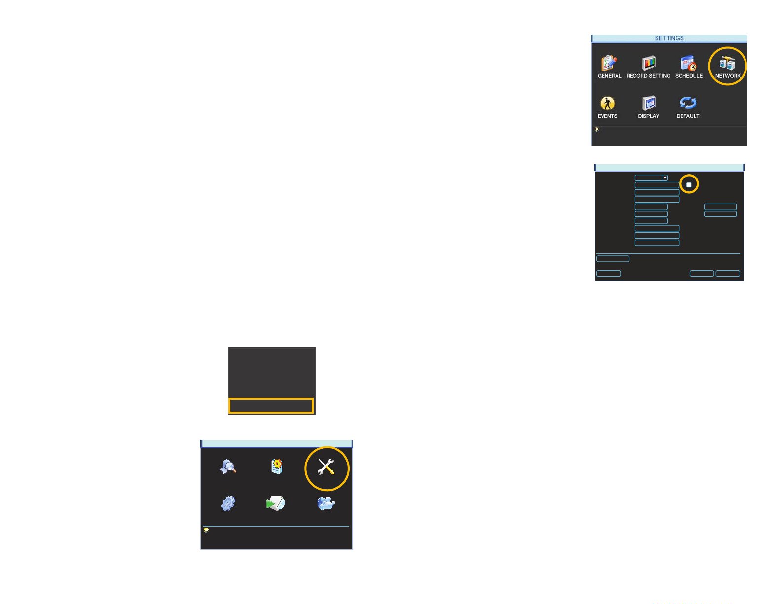
QC-series NVR displays its IP address in the Network window.
STEP 3. Click on the Network icon in
the Settings Menu.
STEP 4. Ensure that the box labeled
“DHCP” is lled.
If it is not, please click on the box so
that it is filled in white. Click on Save
and then exit the window. Reopen
the window to see the updated IP
address.
STEP 5. Write down the:
1. NVR’s IP Address
2. Subnet Mask, and
3. Gateway (your Router’s address)
STEP 6. Exit Menu
IP Version
P Address
Subnet Mask
Gateway
TCP Port
UDP Port
Max Connection
Preferred DNS
Alternate DNS
WAN IP
Network Setting
Default
PICTURE 1-3
IPv4
0 . 0 . 0 . 0
1
255 . 255 . 255 . 0
2
0 . 0 . 0 . 0
3
37777
37778
20
0 . 0 . 0 . 0
0 . 0 . 0 . 0
0 . 0 . 0 . 0
PICTURE 1-4
NETWORK
HTTP Port
RTSP Port
DHCP
80
554
Save Cancel
You may now proceed to Section 1.2 Advanced Settings. However, if you are unable to
obtain an IP address from your router, please proceed to Section 1.3 Static IP.
STEP 1. Select Main Menu from the
Shortcut Menu.
Search
Record
Remote Device
Alarm Output
Main Menu
PICTURE 1-1
STEP 2. Click on the Settings icon in
the Main Menu
SEARCH INFO SETTING
MAIN MENU
ADVANCED BACKUP SHUTDOWN
PICTURE 1-2
6 7
Page 5
1.2 OPENING PORTS
To make your NVR accessible from outside of your local network, you have to “forward” ports
85 and 37777 through your router to your NVR’s IP address. The most preferred - and easiest
- method is UPnP. This is the method used by the Startup Wizard and for most users, the
NVR should connect automatically. If not, we offer some other methods which should work
for the majority of users. You will only need to use one of these methods - which are the same
if you are using a Macintosh or Windows PC. If you are unable to connect your NVR to the
Internet using any of these procedures, the likely cause is the presence of multiple routers on
your network. The solution is covered in Section 1.7 Resolving Connection Issues.
OPTION 1: UPNP
The QC series of NVRs come configured to take advantage of the latest networking
technology, UPnP or Universal Plug ‘n Play right out of the box. If you have an UPnP-enabled
router with that function turned on, you will only need to plug the NVR into your network and
you will then be able to proceed to the end of this section.
Consult your router’s manual to determine
whether it has UPnP or not. Please note that,
as of this writing, 2Wire brand routers do not
have the UPnP feature. If you do not have a
UPnP-enabled Router, you will have to utilize
another method to forward your ports.
If you wish to ensure that UPnP is turned on
in your NVR, go to the Network window as
described above, and check that the UPNP
option is checked in the Advanced Settings
area in the lower part of the window. If it is
not checked, click on the box to add the
check, then click on Save before exiting the
window. When you reopen the window, the
box should be checked.
IP Version
P Address
Subnet Mask
Gateway
TCP Port
UDP Port
Max Connection
Preferred DNS
Alternate DNS
WAN IP
Network Setting
Default
NETWORK
IPv4
0 . 0 . 0 . 0
255 . 255 . 255 . 0
0 . 0 . 0 . 0
37777
37778
20
0 . 0 . 0 . 0
0 . 0 . 0 . 0
0 . 0 . 0 . 0
PICTURE 1-5
HTTP Port
RTSP Port
DHCP
80
554
Save Cancel
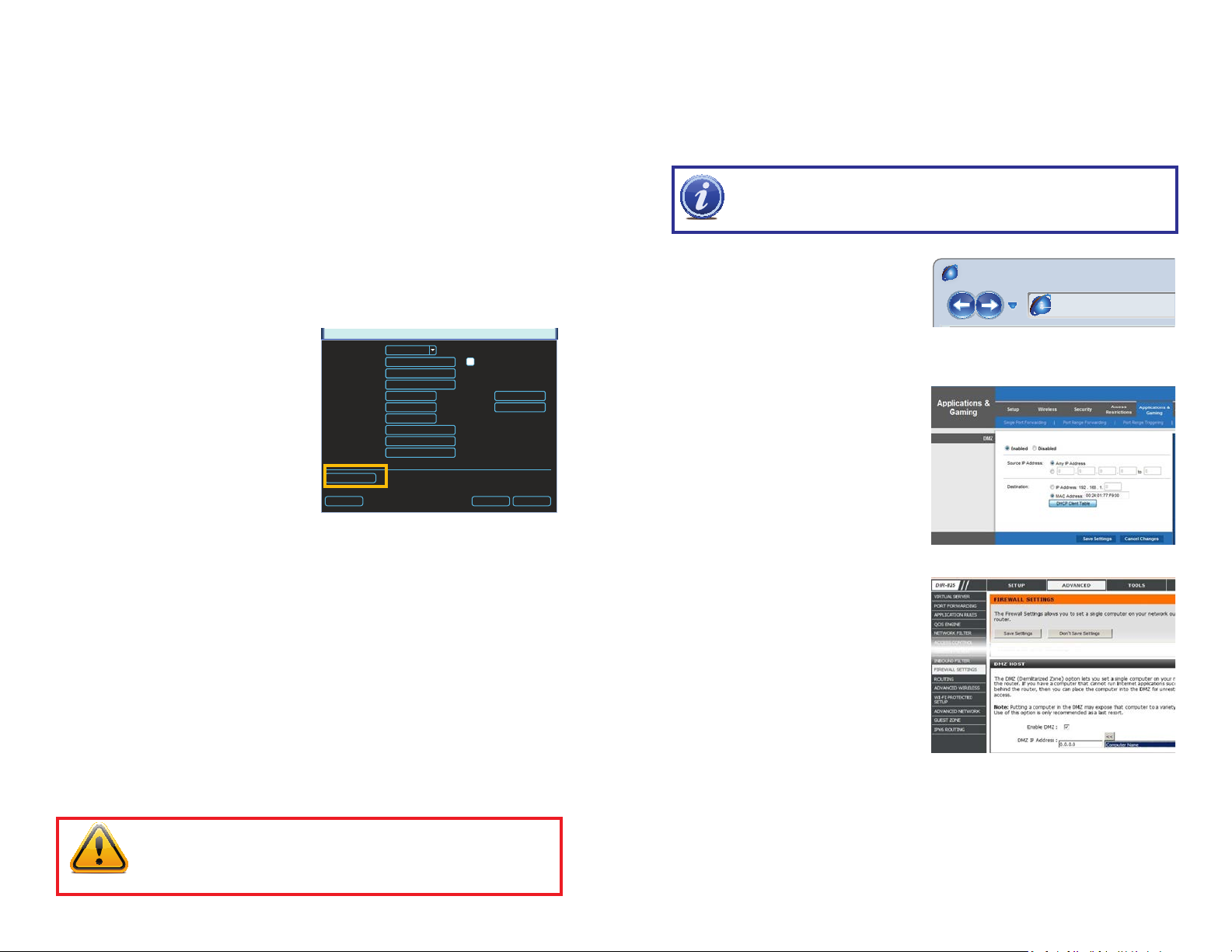
OPTION 2: OPENING PORTS USING DMZ
Accessing your router’s DMZ controls:
The exact location of DMZ within the router’s settings vary by manufacturer so please consult
your router’s manual for the location of this feature. The method for accessing your router’s
settings, however, is pretty standard.
NOTE! If you are an AT&T Internet or Uverse customer, you should follow the
instructions laid out in Option 3 as they specifically apply to the brand of router
used by AT&T.
STEP 1. On a computer connected to
the same router as the NVR, open a
web browser and enter the Gateway
(Router’s IP address) into the browser
window’s address bar to access your
router.
STEP 2. Locate the DMZ settings in
your router. Each manufacturer is
different so please consult your
router’s manual for the location of this
setting. Two examples are shown at
right.
STEP 3. Enable DMZ.
STEP 4. Enter the NVR’s IP address.
Browser - Windows Internet Explorer
hp://10.6.196.6
PICTURE 1-6
PICTURE 1-7
STEP 5. Click on Apply or Save to
preserve your settings.
Leave your router control panel open as you
will need to obtain DNS information from
your router in Section 1.5 Domain Name
System (DNS). You should now proceed to
the section entitled Confirming that Ports
are Opened.
PICTURE 1-8
IMPORTANT! If you connect your system to your network using UPnP you
should NOT forward your ports as described later in this section as it will
create connectivity problems. You may skip to Confirming that Ports are
Opened.
8 9
Page 6
OPTION 3: OPENING PORTS USING DMZ ON 2WIRE ROUTERS
r
Page Safety Tools
This page will serve as a free utility for remotely verifying a port is open or closed. It will
be useful for users who wish to check to see if a server or ISP is blocking certain ports.
Accessing your router’s DMZ controls:
2Wire brand routers are currently the exclusive router used for AT&T’s Uverse and other
Internet servers. Their configuration protocols are different enough that you should follow
these instructions rather than the generic router instructions in Option 2 if you are an AT&T
customer.
STEP 1. On a computer connected to
the same router as the NVR, open a
web browser and enter the Gateway
(Router’s IP address) into the browser
window’s address bar to access your
router.
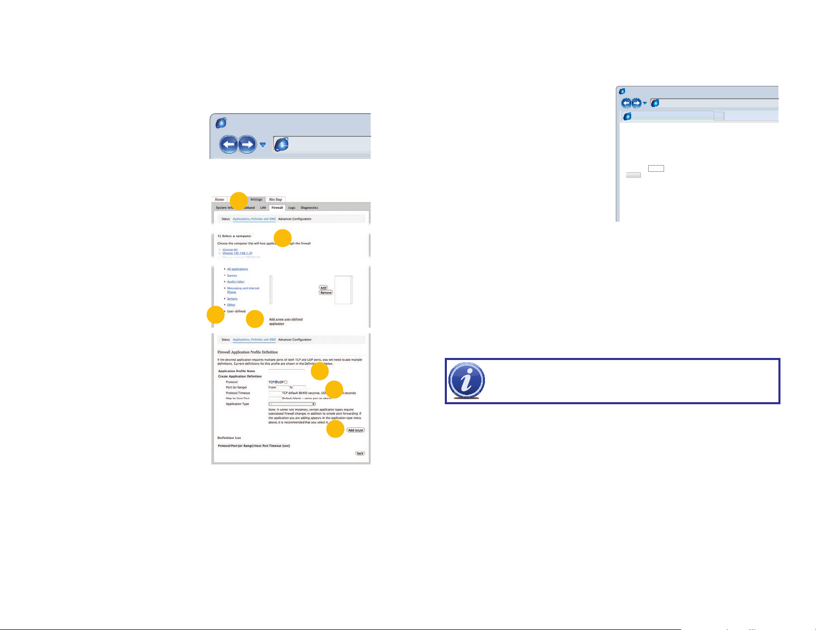
STEP 2. Click on the Settings tab and
then Firewall. Once in Firewall,
click on Applications, Pinholes and
DMZ.
STEP 3. In the Select Your Computer
area, locate your NVR’s IP address
and click on it.
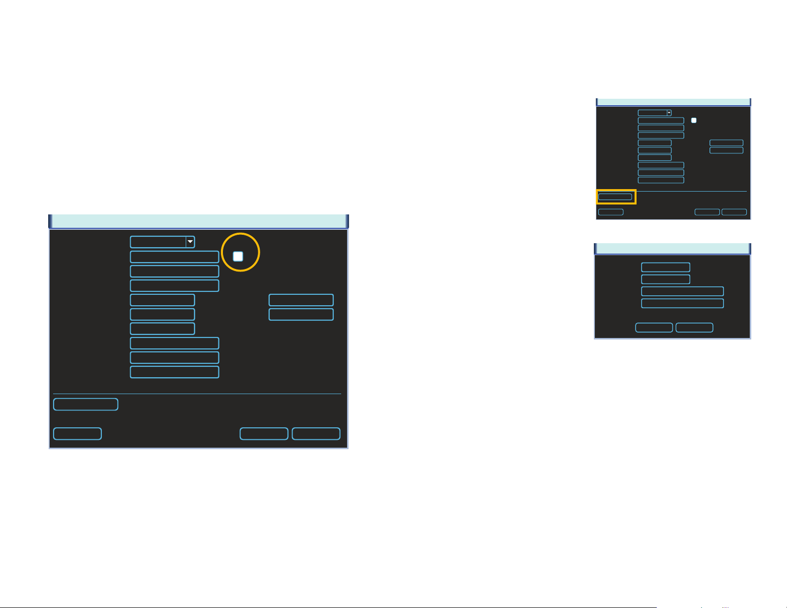
STEP 4. Scroll down to select User
Defined.
STEP 5. Click on Add a new user-
defined application.
STEP 6. In the box labeled Application
Profile Name, enter “NVR”.
STEP 7. Ensure that TCP is selected.
STEP 8. Enter 85 in the From and To
boxes for Port (or Range).
STEP 9. Leave the next two boxes blank
to use the default settings.
STEP 10. Click on Add to List. Your
router will require you to log in to
accept the settings. If you have not
created your own password for your
router, it is the 10-digit System Key
printed on the label on your router
between the square brackets “[ ]”.
STEP 11. Once your settings have been confirmed, repeat Steps 8-10, this time
entering 37777 for the From and To ports.
STEP 12. Click on Back and then select NVR from the list of Applications. Clicking on
Add and then Save.
Leave your router control panel open as you will need to obtain DNS information from your
router in Section 1.5 Domain Name System (DNS).
Browser - Windows Internet Explore
PICTURE 1-9
2
3
4
5
PICTURE 1-10
hp://10.6.196.6
6
7-8
10
CONFIRMING THAT PORTS ARE OPENED
To confirm that your ports have been forwarded successfully, go to www.canyouseeme.org
using a computer connected to the same router as the NVR.
STEP 1. Enter “85” into the box labeled
“What Port?”
STEP 2. Click on the Check button.
STEP 3. You should see a green
“Success” message. If not, return to
the NVR’s Network window and, in
the Network tab, change port 85 to
81 or 83 and click Apply to save your
changes before checking using that
new number on CanYouSeeMe.
STEP 4. Repeat for port 37777. If there
is a problem with port 37777, then try
37000 in the same manner as above.
This website will also display your Public IP address near the top of the page above the box
where you entered your port number. This is the number which you will use to access the NVR
using a web browser or your mobile device from outside of your local network (away from the
building in which your NVR is located).
NOTE! If you are successful after changing from port 85, then you will need
to add that to the IP address when accessing the NVR via the Internet. If, for
example, you changed to port 81, the address would now read 64.245.112.90:81
Browser - Windows Internet Explorer
hp://canyouseeme.org/
Open Port Check Tool
CanYouSeeMe.org - Open Port Check Tool
Your IP: 81.919.622.24
What Port?
Check
Success: I can see your service on
81.919.622.24 on port (85)
Your ISP is not blocking port 85
PICTURE 1-11
10 11
Page 7
1.3 STATIC INTERNAL IP (NETWORK) ADDRESS
Most routers assign connected devices a random IP address that is not currently in use by
another device on your internal network. With the exception of 2Wire brand routers, when
a router or networked device reboots due to a power loss or other issue, the addresses will
change and the port forwarding configuration will no longer work. For that reason, unless
you have a 2Wire router, we recommend changing your NVR’s network setting to a fixed,
or “static” IP address which will not change.
STEP 1. Return to the Network Menu.
STEP 2. Uncheck the box marked DHCP.
STEP 3. Click Save.
Proceed to Section 1.5 Domain Name System (DNS) without closing the window.
NETWORK
IP Version
P Address
Subnet Mask
Gateway
TCP Port
UDP Port
Max Connection
Preferred DNS
Alternate DNS
WAN IP
Network Setting
Default
IPv4
0 . 0 . 0 . 0
255 . 255 . 255 . 0
0 . 0 . 0 . 0
37777
37778
20
0 . 0 . 0 . 0
0 . 0 . 0 . 0
0 . 0 . 0 . 0
HTTP Port
RTSP Port
DHCP
80
554
Save Cancel
1.4 PPPOE
If you are going to attach the NVR directly to a DSL or cable modem instead of to a router
then select the PPPOE option in the Network options. Before you proceed, you will need to
contact your ISP to obtain your User Name and Password. You will not have to worry about
Static IP (previous section).
NETWORK
STEP 1. Click the Network Settings
button.
STEP 2. Double-click on PPPOE to
open the window.
STEP 3. Input the User Name and
Password provided by your ISP into
their respective fields.
STEP 4. Click OK to save your settings.
Click on Save in the Netwok window
before closing that window.
STEP 5. Restart your NVR and return to
the PPPOE window. Your NVR will
have automatically connected to the
Internet and you can use the number
in the IP address field to remotely
access the NVR.
IP Version
P Address
Subnet Mask
Gateway
TCP Port
UDP Port
Max Connection
Preferred DNS
Alternate DNS
WAN IP
Network Setting
Default
User Name
Password
IP Address
IPv4
0 . 0 . 0 . 0
255 . 255 . 255 . 0
0 . 0 . 0 . 0
37777
37778
20
0 . 0 . 0 . 0
0 . 0 . 0 . 0
0 . 0 . 0 . 0
HTTP Port
RTSP Port
PICTURE 1-13
PPOE
0 . 0 . 0 . 0
0 . 0 . 0 . 0
OK Cancel
PICTURE 1-14
DHCP
80
554
Save Cancel
PICTURE 1-12
12 13
Page 8
1.5 DOMAIN NAME SYSTEM (DNS)
Page Safety Tools
ADVANCED
All of your Internet and network connecon details are displayed on this page.
MACINTOSH AND PC USERS
Once you have completed the above sections, you are able to operate your NVR remotely.
The sections below allow you to take advantage of additional features including the ability to
access your NVR using a conventional domain name and having your system send out e-mail
alerts. To access these functions, you will have to access your router to obtain your DNS
(Domain Name System) number.
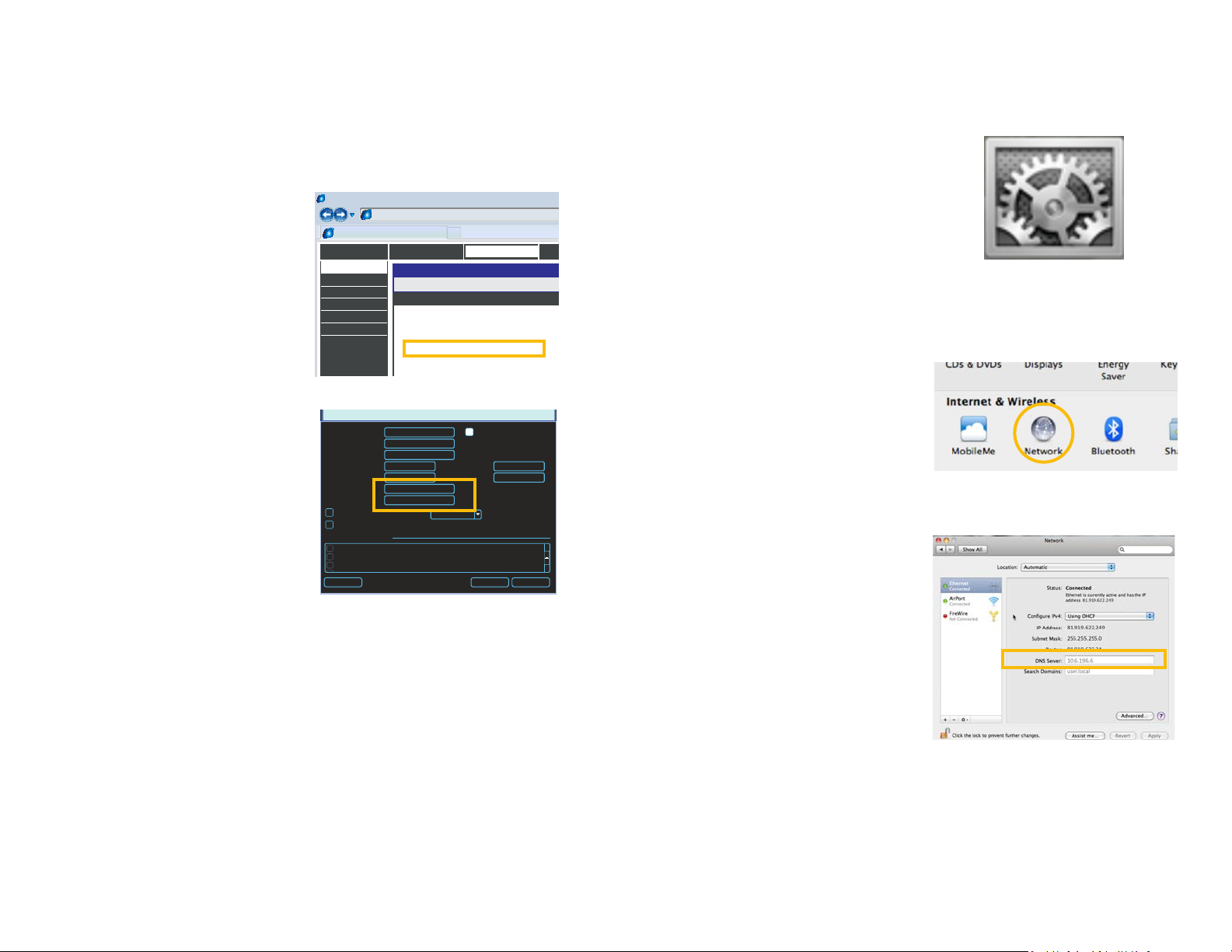
STEP 1. Return to your router’s control
window.
If you did not have to open your
router in a previous step, simply open
a new browser window and enter
the Gateway address (covered in
Section 1.1)
STEP 2. Locate your router’s status
window (may also be named
“Information” or “Info”, it will list the
DNS number. You will only need to
use the primary set of numbers write it down for later use.
STEP 3. In the NVR’s Network window,
enter the DNS number in the area
marked Preferred DNS. You do not
need to have an alternate server.
STEP 4. Click Save to save your
settings.
Browser - Windows Internet Explorer
hp://81.919.622.24
Router
DEVICE INFO
LOGS
STATISTICS
INTERNET SESSIONS
ROUTING
WIRELESS
SETTINGS
DEVICE INFORMATION
WAN
MAC Address :
Subnet Mask :
Default Gateway :
Primary DNS Server :
Secondary DNS Server :
Advanced DNS :
IP Address :
STATUS
00:24:01:77:f9:00
81.919.622.249
255.255.255.0
81.919.622.24
10.6.196.6
(null)
Disabled
PICTURE 1-15
NETWORK
IP Address
Subnet Mask
Gateway
TCP Port
UDP Port
Preferred DNS
Alternate DNS
ADVANCED SETTING
DDNS No Available DDNS Setup
UPNP Port Forwarding
EMAIL MailServer: 25
FTP Record FTP : 0.0.0.0
Default Save Cancel
0 . 0 . 0 . 0
0 . 0 . 0 . 0
0 . 0 . 0 . 0
37777
37778
0 . 0 . 0 . 0
0 . 0 . 0 . 0
Transfer Mode
LAN Download
HTTP Port
Max Connection
Latency
DHCP
80
20
PICTURE 1-16
MACINTOSH COMPUTERS
In addition to retrieving the DNS info from the router, Macintosh users can get it from the
computer’s Network window.
STEP 1. Click on the System
Preferences icon at the bottom of
the Macintosh’s screen.
PICTURE 1-17
STEP 2. Click on the Network icon.
PICTURE 1-18
STEP 3. Make sure that your network
connection is highlighted in the list of
connections to the right of the main
part of the Network window and
that its status reads “Connected.”
The DNS server information will be
shown. Write this down for use in the
next section.
PICTURE 1-19
14 15
Page 9
1.6 DYNAMIC DOMAIN NAME SERVICE (DDNS)
This is an optional step which allows you to take advantage of Dynamic Domain Name
Service, or DDNS. Not to be confused with DNS above, DDNS allows you to enter a
conventional web address when remotely logging into your NVR from outside of your network.
It also allows you to avoid having to repeat Sections 1.3 and 1.5 when/if your ISP reassigns
IP addresses. Q-See offers DDNS service for free at www.MyQ-See.com and your NVR is
configured to accept account information from that site.
STEP 1. Open a browser window and go
to www.MyQ-See.com
STEP 2. Register with the website and
follow the instructions for creating
a domain name. The website will
display your pubic IP address and
your domain name which will look like
this: http://example.myq-See.com
STEP 3. In your NVR, open the Network
window.
STEP 4. In the Advance Settings area at
the bottom of the window, scroll until
you find DDNS and double-click on it
to open the DDNS window.
STEP 5. Check the Enable box and
select MyQ-See.com in the DDNS
server pull-down menu.
STEP 6. Enter your account information
– including the user name and
password that you used when
creating your domain name .
STEP 7. Click the Save button to
preserve your settings.
STEP 8. When you return to the
Network window, ensure that the
DDNS box is checkmarked before
clicking on Save as well before
closing.
NEW USER REGISTRATION
EMAIL ADDRESS
PASSWORD
PASSWORD
CONFIRM
FIRST NAME
LAST NAME
SECURITY
QUESTION..
ANSWER
CONFRIM
YOU’RE HUMAN
My first phone number
New Captcha
Enter the text you see above
Submit
Reset
Submit
Reset
PICTURE 1-20
NETWORK
IP Address
Subnet Mask
Gateway
TCP Port
UDP Port
Preferred DNS
Alternate DNS
ADVANCED SETTING
DDNS No Available DDNS Setup
UPNP Port Forwarding
EMAIL MailServer: 25
FTP Record FTP : 0.0.0.0
Default Save Cancel
0 . 0 . 0 . 0
0 . 0 . 0 . 0
0 . 0 . 0 . 0
37777
37778
0 . 0 . 0 . 0
0 . 0 . 0 . 0
Transfer Mode
LAN Download
HTTP Port
Max Connection
Latency
DHCP
4
80
20
PICTURE 1-21
DDNS
DDNS Type
Server IP
Port
Domain Name
User Name
Password
Update Period
Q-SEE DDNS
myq-see.com
85
300
6
5
Enable
sec.
1.7 RESOLVING CONNECTION ISSUES
There are several hardware-related situations which can prevent the NVR’s port from being
properly forwarded. The presence of multiple routers or the routers not featuring UPnP or
DMZ are the two most common issues.
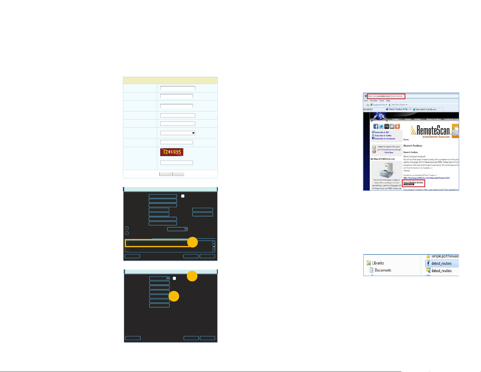
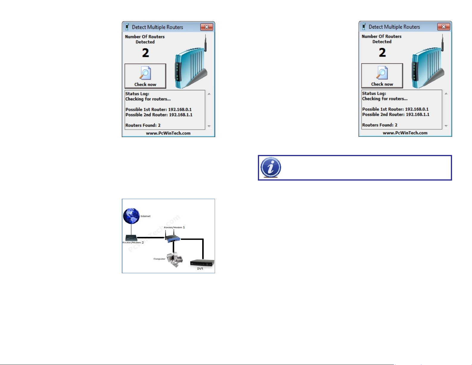
DETERMINE THE NUMBER OF ROUTERS ON THE NETWORK
If there is more than one router between the NVR and the Internet it will block communication
to and from your system. To find out the number of routers on your network, you will need to
download a FREE router detection program.
STEP 1. Go to http://www.pcwintech.
com/shanes-toolbox
STEP 2. Click on Detect Multiple
Routers to begin the download.
STEP 3. Unzip the application to install it.
STEP 4. Click on the detect_routers
application to run it.
PICTURE 1-23
PICTURE 1-24
Default Save Cancel
PICTURE 1-22
16 17
Page 10
STEP 5. Click on CHECK NOW to
detect how many Routers are in the
network.
PICTURE 1-25
STEP 6. If there is only one router detected, and you are using UPnP, then you will need
to turn off that setting and attempt to connect using DMZ as described in Section
1.2 Opening Ports.
If you are using DMZ, check to make sure that the UPnP option is turned off.
If Multiple Routers are Detected
If there are multiple routers, you will see a
display similar to Picture 1-26.
If so, it may be preferable to connect your
NVR and computer to the router that
connects directly to the Internet. However,
this is not always possible depending upon
your particular situation.
SETTING UP DMZ IN ROUTER 2
STEP 1. Login into Router 1 by putting
the IP of Router 1 into the Internet
Explorer browser, as in the example
shown in Picture 1-25 where the IP
address of Router 1 is 192.168.0.1
STEP 2. Find the status page on the
router settings that shows the WAN/
Internet IP address and write it down
this WAN IP address.
STEP 3. Log into the Router 2 by putting
the IP of Router 2 into the Internet
Explorer browser, as in example
shown in Picture 1-26 where the IP
address of Router 2 is 192.168.1.1
STEP 4. Find the DMZ page in the
router settings.
STEP 5. Enter the WAN IP for Router 1
into the DMZ page and enable DMZ.
NOTE! If you do not have a DMZ setting in the router, check to see if there
is a Bridge setting. If so, then use the Bridge setting instead of DMZ.
STEP 6. Save your changes.
You have forwarded the ports on the router to which the NVR is connected, to the IP address
of the NVR, and set the second router to pass the connection to this router.
PICTURE 1-26
PICTURE 1-26
In this case, you will need to proceed with the next section and set up DMZ in the second
router to allow communications to pass through it from the first. If only one router is detected
you will need to consult your router’s manual.
18 19
Page 11
ADDITIONAL SETTINGS
CHAPTER 2
2.1 ADVANCED NETWORK SETTINGS
Now that you’ve successfully connnected your NVR to your network and to the Internet, there
are additional features which you can take advantage of. These settings allow your NVR to
send out e-mail alerts as well as post images and records to an FTP site. In addition, you can
see which users are online, limit online access and more.
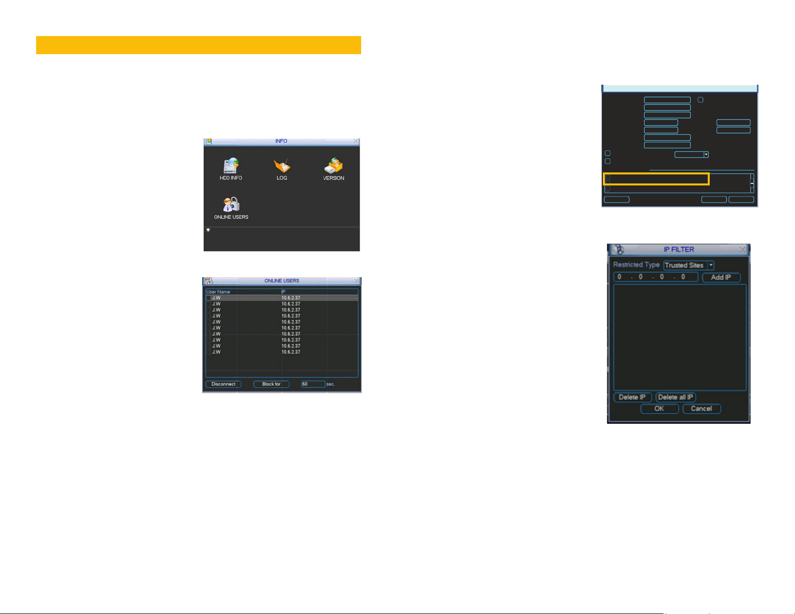
ONLINE USERS
A list of users accessing the NVR from over
the network or through the Internet is shown
in Online Users menu which itself is found in
the Info menu.
PICTURE 2-1
The user’s name as well as the IP address
used to access the NVR is displayed.
If you have proper system management rights
(Configured in Account, See Section 4.4
Advanced in the User’s Manual for full
instructions), you can disconnect or block
a user. The maximum time a user can be
disconnected is 18 hours (65,535 seconds).
PICTURE 2-2
IP FILTER
You can also improve security by controlling remote access to your NVR using the IP Filter.
This feature enables you to allow online users only from approved IP addresses. Up to 64
addresses may be entered.
The IP Filter window is accessed through
the Advanced Settings area of the
Network menu.
Enter the trusted IP addresses into the field at
the top of the window and select Add IP to
add that address to the list of those allowed
to connect to the NVR.
Once this feature is enabled, only IP
addresses within this list can be used to
access the NVR. If this feature is not enabled,
then users can connect from any IP address
if they have the correct user name and
password information.
IP Address
Subnet Mask
Gateway
TCP Port
UDP Port
Preferred DNS
Alternate DNS
ADVANCED SETTING
IP Filter Trusted Sites : 0
NTP windows.time.com : 24
PPOE
DDNS No Available DDNS Setup
Default Save Cancel
NETWORK
0 . 0 . 0 . 0
0 . 0 . 0 . 0
0 . 0 . 0 . 0
37777
37778
0 . 0 . 0 . 0
0 . 0 . 0 . 0
Transfer Mode
LAN Download
Latency
PICTURE 2-3
DHCP
HTTP Port
Max Connection
80
20
PICTURE 2-4
20 21
Page 12
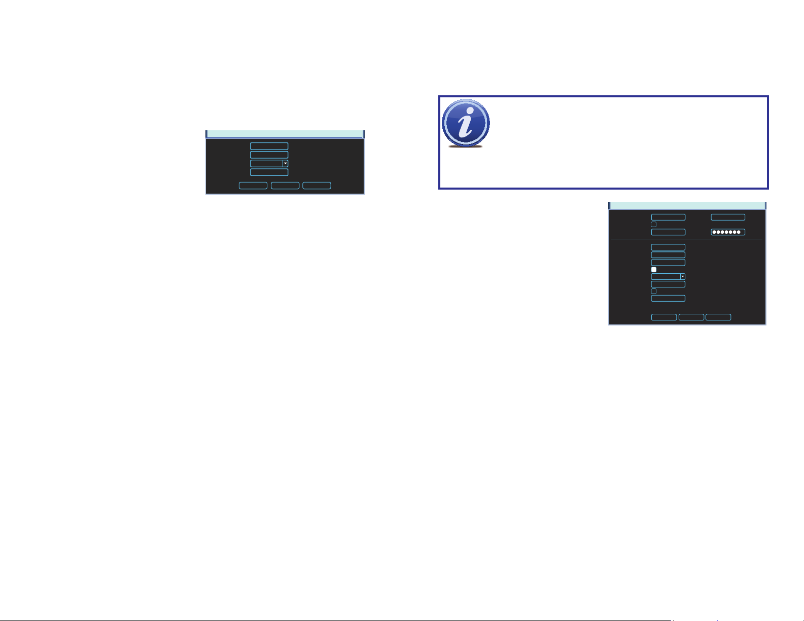
NTP
Network Time Protocol (NTP) is used to synchronize the time of a computer or other device
connected to the Internet. Utilizing this feature allows your NVR to keep an accurate time as
well as automatically adjust to Daylight Savings Time changes.
NTP was set up as part of the Startup Wizard process, but you can always return via the
Advanced Settings area of the Network menu to make adjustments.
Server IP - The default server used to
obtain accurate time is the Windows
server, but you can manually enter in
another.
Port - This is the port that the NVR
will use to contact the server.
Server IP
Port
Time Zone
Update Period
OK Cancel Synchronize
Time Zone - You will need to set your
time zone. For North America these
are:
Eastern Time Zone = GMT-5 Central Time Zone = GMT-6
Mountain Time Zone = GMT-7 Pacific Time Zone = GMT-8
Alaskan Time Zone = GMT-9 Hawaii Time Zone = GMT-10
Update Period - This is the frequency at which the NVR will check the time with the
server.
Synchronize - Clicking this will cause the NVR to update the time immediately.
NTP
time.windows.com
123
GMT-8:00
24
PICTURE 2-5
Hours
Several NVR functions allow you to send out e-mail alerts when specific events occur.
Configuring this feature lets you set the NVR up to send out alerts via e-mail to a single
recipient. You may need to contact your e-mail provider or IT department for some required
information.
NOTE! Depending upon your settings, the system can generate a lot of e-mail
alerts. For that reason, we recommend setting up a dedicated e-mail address
specifically for the system to send alert notices. If you do not have your own
e-mail system (such as a corporate mail server) you should consider using a
limited amount of e-mail traffic we specifically recommend using Google’s Gmail service with
its higher limit. Similarly, you will want the alert e-mails to go to a different account than the
one sending them. This will ease your management of these alerts.
SMTP Server – This the SMTP server IP
Port – This is the port your mail provider uses
User Name and Password – These are for
Title – This is the subject line of e-mails
Receiver – This is the recipient e-mail
Attachment – This allows the e-mail to
SSL Enable – The system supports SSL
Interval – This adjusts the amount of time
free e-mail provider. However, because many free e-mail services allow only a
EMAIL
name
the sending e-mail address and were
set up when you created the e-mail
account.
generated by this NVR.
account.
SMTP Server
Anonymous
User Name
Receiver
Sender
Title
Attachment
Encrypt Type
Event Interval
Health Enable
Interval
smtp.gmail.com 465
DVR ALERT
NONE
3
60
Port
Password
Min.
Min.
PICTURE 2-6
include one or more snapshots as
attachments
encryption when this is enabled.
that will pass before the NVR sends
out another e-mail. The interval can
be set from 0 seconds to ten hours
(3600 seconds). If you are getting
too many e-mails, you may wish to
increase the length of the interval.
Using this feature also helps prevent
overloading your outgoing e-mail
server.
TestOK Cancel
22 23
Page 13
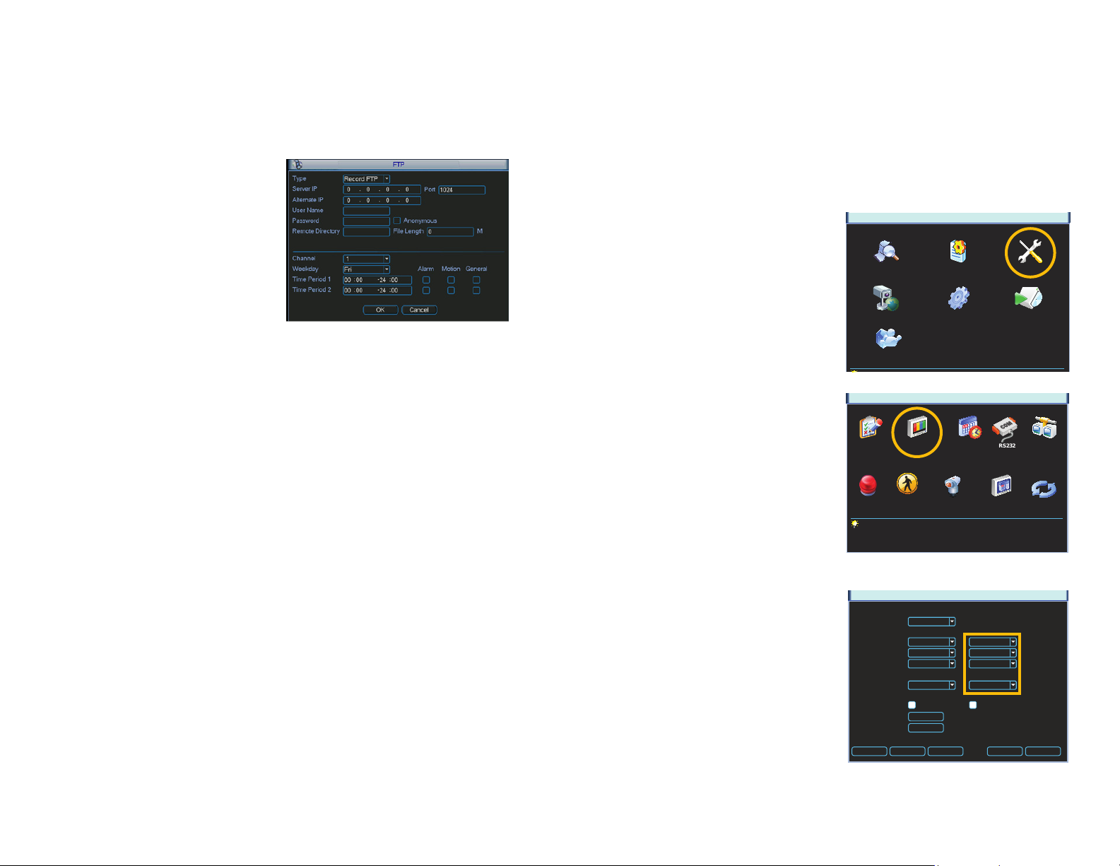
FTP
File Transfer Protocol (FTP) allows you to securely share, manage, and distribute files over the
internet. You will need to already have a server and FTP service tool to utilize this feature on
the NVR.
Follow the software’s instructions to set up your service, password and FTP folder. You will
need to grant Write privileges to the FTP upload user.
Enter the FTP server address, port and
remote directory. If the remote directory is left
blank, the system will automatically create
folders according to the IP, time and channel.
User Name and Password – This is the
account information created when
you set up your FTP and is used to
allow the NVR to log into the server.
File Length – This is the maximum length (in
minutes). Files under the maximum
will upload completely. Files longer
than the maximum limit will only
upload to that limit and not continue.
If the value is left at 0, there is no limit
and the system will upload all files
completely.
The lower portion of this window allows you to set up to two upload periods for each channel.
Recordings made during the time(s) selected will be uploaded to the server. You can specify
which type of incidents will be uploaded as well.
PICTURE 2-7
2.2 ADDITIONAL SETTINGS
You may need to adjust your settings in the Record Setting and Account windows to ensure
trouble-free remote monitoring. Complete instructions on their use can be found in Chapter
5 of the User Manual.
RECORD SETTING
Whether monitoring your NVR via a computer or your smartphone, you may need to adjust
the Extra Stream settings to match the capabilities of your network or wireless provider.
MAIN MENU
The Record Setting window is located in the
Setting menu.
If you are experiencing any performance
issues in your remote or mobile viewing,
adjust the settings in the Extra Stream
portion of the Record Setting window. Most
QC-series NVRs will only allow the use of the
smaller QCIF (Quarter CIF) resolution format
for this second stream. The CBR bit rate
type is generally better for remote streaming.
Adjust the frame rate to find the best
performance for your particular situation.
SEARCH INFO SETTING
ADVANCED BACKUPREMOTE DEVICE
SHUTDOWN
PICTURE 2-8
SETTING
RECORD SETTINGGENERAL SCHEDULE NETWORKRS232
EVENTSALARM PAN/TILT/ZOOM DISPLAY DEFAULT
PICTURE 2-9
Remember that changes made in the Extra
Stream section do not effect how your NVR
records to its own drive.
Channel
Compression
Resolution
Frame Rate (FPS)
Bit Rate Type
Bit Rate (Kb/S)
Reference Bit Rate 384-2048Kb/S
Audio/Video
Copy Paste Default Save Cancel
RECORD SETTING
Main Stream
1
H.264
D1
25
Constant
2049
OVERLAY
SNAPSHOT
Extra Stream
H.264
CIF
7
Constant
160
PICTURE 2-10
24 25
Page 14
ACCOUNT
When logging in remotely, you will have the same privileges and authorities as you do when
accessing the NVR directly. This includes which cameras can be monitored and played back,
PTZ controls and other aspects.
The Account window can be found in the
Advanced menu.
SEARCH INFO SETTING
ADVANCED BACKUP SHUTDOWN
MAIN MENU
PICTURE 2-11
REMOTE MONITORING
CHAPTER 3
3.1 ACCESSING YOUR NVR REMOTELY FROM A COMPUTER
You can access your NVR remotely using a computer on the same network as your system or
from any computer using the Internet. QC-series NVRs can be accessed on a PC using the
Windows operating system either through Internet Explorer or by using the PSS software that
is included on the Manuals and Software CD that came with your system.
ACCESSING THE NVR USING INTERNET EXPLORER
Accessing your NVR using Internet Explorer is generally as simple as using an interactive
website. Some users may need to configure Microsoft’s built-in ActiveX controls prior to
logging into their NVR in order to ensure smooth operation.
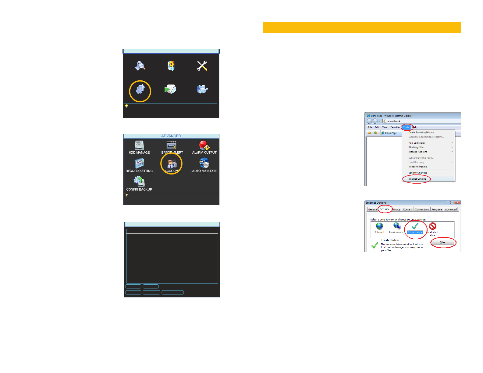
Setting Up ActiveX Control
STEP 1. Open Internet Explorer
STEP 2. Click on Tools
STEP 3. Select Internet Options in the
pull-down menu
PICTURE 3-1
PICTURE 2-12
STEP 4. Click on the Security Tab
STEP 5. Select Trusted Sites
If you do not log out of your NVR - or if
you wish to allow multiple users to monitor
the NVR using the same account - then
you should select the account, then click
on Modify User. Check the box next to
“Reusable” for that account before saving
3 User Group Status
1 admin admin Normal
2 local admin admin Login Local
3 user user Default User
ACCOUNT
STEP 6. Click on the Sites button
PICTURE 3-2
and exiting the window.
Add User Modify User
Add Group Modify Group Modify Password
PICTURE 2-13
26 27
Page 15
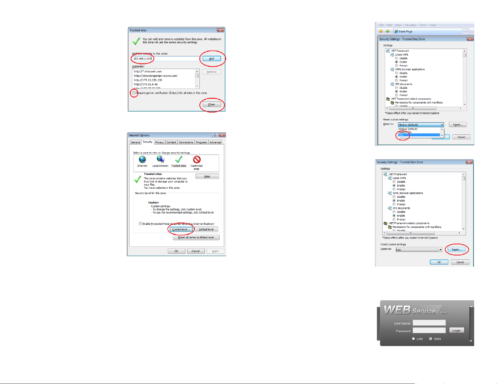
STEP 7. Uncheck the “Require server
verification (https:) for all sites in
this zone” button.
STEP 8. Type the NVR’s IP address
(obtained during Network Setup)
or DDNS domain name into the “Add
this website to the zone:” box.
STEP 9. Click the Add button
STEP 10. Close the window.
STEP 11. Click the Custom level…
button.
STEP 12. Pull down the “Reset to:”
menu button and select Low
PICTURE 3-3
PICTURE 3-5
STEP 13. Click the Reset button
STEP 14. Click “Yes” when asked, “Are
you sure you want to change the
setting for this zone?”
STEP 15. Click OK
STEP 16. Click Apply
STEP 17. Click OK
PICTURE 3-4
STEP 18. Close Internet Explorer
PICTURE 3-6
Open a browser window in Internet Explorer and enter the IP address or DDNS name
(obtained in Section 1.1) into the address bar.
You will see a log in screen similar to that
shown in Picture 3-7 or yellow alert bar at
the top of the window asking for permission
to open an ActiveX application. Allow it to
install webrec.cab control to reach the
sign-in screen.
Proceed to Section 3.2 Monitoring with
Internet Explorer for instructions on
logging in and remote monitoring.
PICTURE 3-7
28 29
Page 16

Troubleshooting: User Account Control for Windows Vista and Windows 7
Some users of computers using Windows Vista or Windows 7 operating systems may receive
an error message informing of a codec that is missing or not installed. This conflict can be
resolved by turning off User Account Control (UAC).
Windows Vista
STEP 1. Open the Control Panel
(accessible by clicking on the
Windows icon in the lower left of your
screen.
PICTURE 3-12
STEP 6. Uncheck the box next to “Use
User Account Control (UAC) to help
protect your computer.”
STEP 2. Select User Accounts and
Family Safety.
STEP 3. Select “Add or Remove User
Account.”
STEP 4. Select the desired user account.
STEP 5. Select Turn User Account
Control on or off
PICTURE 3-8
PICTURE 3-9
PICTURE 3-10
PICTURE 3-11
STEP 7. You will then be asked to restart
your computer for the change to take
effect.
Windows 7
STEP 1. Open up the Start Menu
(accessible by clicking on the
Windows icon in the lower left of your
screen.
STEP 2. Type “uac” into the search bar
and hit ENTER. The User Account
Control will open or you will be offered
a link to click to open it.
STEP 3. Move slider to lowest setting
and press OK.
PICTURE 3-13
Microso Office Outlook 2007
Scky Notes
iTunes
Adobe Acrobat
All Programs
uac
PICTURE 3-14
Devices and Printers
Default Programs
Help and Support
Shut down
PICTURE 3-15
30 31
Page 17

ACCESSING THE NVR USING PSS ON A PC
In addition to using Internet Explorer to access the NVR from a remote computer, Windows
PC users can also install and use the PSS (Pro Surveillance Software) program included on
the CD that was packaged along with your NVR. The file is also available for free download on
Q-See.com, but you will need to download an extraction program to be able to use PSS. One
extraction program can be downloaded for free at at http://rarlabs.com/download.htm
STEP 1. Double click on the Pro
Surveillance System icon in the PSS
for Windows folder to extract and
install the program.
PICTURE 3-16
STEP 2. A shortcut icon for the PSS
application should appear on
the desktop. If you do not see it,
the program can be found in the
Programs folder.
STEP 3. Double click on the icon to run
the program.
Please go to Section 3.3 Pro Surveillance Software (PSS) for instructions on controlling
your NVR using PSS.
PSSPSS
PICTURE 3-17
STEP 1. Double click on the PSSSetup.
pkg icon in the PSS for Mac folder
to extract and install the program.
STEP 2. A shortcut icon for the PSS
application should appear on
the desktop. If you do not see it,
the program can be found in the
Applications folder.
STEP 3. Double click on the icon to run
the program.
OSX 10.8
Apple’s OSX version 10.8 introduced fundamental changes in how the computer interacts
with certain programs. This has led to some instability in the PSS software. This issue is
currently being addressed with a completely new 10.8-compatible version of the PSS sofware
available in December, 2012. In the interim, users running 10.8 are directed to use PSS Mini
software available on your CD, or by download from our site at www.Q-See.com/Support.
You will not need to download or install XQuartz to use PSS Mini.
You can also use PSS Mini on systems running 10.6 or 10.7 if you chose, without needing the
XQuartz plug-in.
PICTURE 3-18
PSSPSS
PICTURE 3-19
ACCESSING THE NVR ON A MAC
Mac users will not have to turn off UAC or enable ActiveX to access their NVR from their
computer. Determine which version of the Mac OS you are using before proceeding. You can
find which version of the Macintosh operating system your computer is running by selecting
About This Mac from the Apple menu in the upper left of your screen.
OSX 10.6 and 10.7
If your computer is running OSX 10.6 or 10.7 you will need to install the latest version of the
XQuartz application. It is available for free from CNet.com at:
http://download.cnet.com/XQuartz/3000-2094_4-10912185.html
You will also need to install and run the PSS (Pro Surveillance Software) program included on
the CD that was packaged along with your NVR. The file is also available for free download on
Q-See.com, but you will need to download an extraction program, UnrarX to be able to use
the application. It is available for free at http://www.unrarx.com
PSS will automatically launch and run inside of XQuartz and will show up as “X11” in the
application bar at the top of the screen.
PSS Mini is installed and operated in the same manner as is PSS start with Step 1, above for
installation), but a few features are not available:
• User will need to manually add a DVR or camera to the list.
• Can display maximum 16 channels at a time.
• Cannot remotely congure or reboot DVR.
• No Emap feature.
• Cannot record or backup video to computer’s hard drive.
• Snapshot feature is disabled
Please note that these features only apply to operations on the Mac computer itself. The
DVR’s functionality is unchanged as are the operations when using QC view on a mobile
device. These features will be restored in the new software.
For instructions on remotely controlling your NVR using PSS, please go to Section 3.3 Pro
Surveillance Software (PSS).
32 33
Page 18

3.2 REMOTE MONITORING WITH INTERNET EXPLORER
At present, the web-based monitoring software can only be utilized with Internet Explorer
7, 8 and 9. Safari is not supported. Google Chrome Plus and Mozilla Firefox require the
Internet Explorer plug-in. Macintosh users and PC owners who do not wish to use Internet
Explorer should use the version of Pro Surveillance Software appropriate to your platform.
This software can be found on the Manuals and Software CD that came with your NVR, or it is
available for download from www.Q-See.com.
STEP 1. - Enter the IP address or the DDNS address obtained in Section 1.5 into an
Internet Explorer window. You will see the Login screen shown in Picture 3-20
STEP 2. Enter the User Name and
Password in the appropriate fields.
The default user name and password
are admin and admin.
To resolve this issue, select Compatibility
View in the Tools drop-down to the upper
right of the Explorer Window.
PICTURE 3-21
When you log into your NVR for the first time,
your display may put the Camera Control and
Picture Control panels below the Real-Time
Monitor (Picture 3-21) window rather than
to the right as intended (Picture 3-22).
IMPORTANT! We strongly recommend that you modify your password after
you first log in for improved security.
PICTURE 3-20
PICTURE 3-22
The page will refresh, and you will have to log
in again before continuing.
Within the Explorer window, the display
has several sections, each with their own
function.
PICTURE 3-23
34 35
Page 19

1
2
5
6
PICTURE 3-24
Item # Area Function
1 Operations Separate controls for NVR features including video
search, alarms and logging out
2 Channel Controls Select which cameras to display along with activating
bi-directional chat if available
3 PTZ Controls Controls for any attached PTZ cameras
4 Picture Controls Adjust hue, brightness, etc.
5 Real-Time Monitor Live viewing of selected channels
6 Image View Options Controls for number of channels viewable at once plus
other options.
Channel Controls
In this area, you can select which cameras to view, which data stream to use,
activate two-way communication with someone near a camera and play back a recorded
video that has been saved on your computer.
3
Cameras - Clicking on one of the camera
icons will open the corresponding
channel. Cameras will be numbered
4
as they are on the NVR.
Stream - You can select whether to use the
main data stream or the smaller Extra
Stream (also known as a SubStream)
which may provide smoother video if
you have bandwidth issues.
Open All - Opens all available cameras
Refresh - Refreshes camera list
Start Dialog - If you have a microphone
and speaker co-located with a
camera and you have a microphone
connected to the input port on the
back of the NVR, you can initiate a
bi-directional dialog with a person
near that camera. There are two
options: DEFAULT and G711a.
Local Play - Open and playback a recorded
video file saved on your computer.
The files are saved as .dav format
which will require conversion to .avi
format tusing the Player software
included on the CD to play in another
application.
PICTURE 3-25
It should be noted that the screen outlined in green is the one that will be affected by any
control inputs and that clicking on another screen will highlight that one instead, making it the
one that will be controlled.
Operations
There are five operations that can be selected; Search, Alarms, Config, About and Logout.
Double-clicking on any of these will open a window over the live display allowing you to set or
enable options and functions. Their use will be described later in this section.
The color of the camera icons indicate their status:
Icon Status
Online
Offline
Playing
Back
In live view mode, cameras can be turned on and off by clicking on their icon. They can be
positioned as you desire within a multi-screen mode by clicking on a frame to highlight it and
then clicking on the camera’s icon to make it gold (active).
36 37
Page 20

PTZ Controls
You must have already connected and set up one or more PTZ cameras as described in
Chapter 6 PTZ Cameras in the User Manual before being able to use this function. This
control panel operates just like the PTZ controls on the NVR itself.
While you can refer to 6.2 PTZ Control and
Setup in the User Manual for instructions
on general PTZ operation, there are a couple
of features in this control panel that should
be noted:
The arrow button at the bottom of the control
panel will show or hide the controls for
utilizing presets, tours and etc.
Picture Controls
This control panel combines two tabs which allow you to control the appearance of the
on-screen images (Color tab) as well as set the location where downloaded image and video
files will be saved (More tab).
The color controls will only affect the screen
view that is highlighted in green in the RealTime Monitor window. They are, in order:
Brightness, Contrast, Hue and Saturation and
are adjusted by moving the respective slider.
Selecting Reset will revert the settings to their
defaults.
PICTURE 3-28
Pic Path and Rec Path both operate in the
same manner in allowing you to set where
downloaded still images and recorded videos,
respectively, will be saved on your hard drive.
PICTURE 3-29
Clicking either will open a Set Path box
(Picture 3-30). You can navigate to the
desired save location as you would saving
any file on the computer using the Browse
PICTURE 3-26
Selecting PTZ Set will open a window
(Picture 3-27) which will allow you to set up
new presets, tours and other PTZ commands
in a similar manner as on the NVR itself.
PICTURE 3-27
option.
PICTURE 3-30
Videos will be saved as .dav format and will need to be converted using the included General
Player software. Still images will be saved as .jpg files which can be viewed my most image
viewing programs. Videos and still images can be saved in the same folder or in different
areas of the computer depending on your preference.
Reboot will attempt to restart the computer. It will not work if you do not have administrator
privileges on that computer or if there is another local user logged into the computer.
38 39
Page 21

Real-Time Monitor
Live monitoring and recorded video playback takes place in the Real-Time Monitor section of
the window. The number of screens being viewed at once is set with the Image View Options
at the bottom of the screen (described below), but at any time, you can double-click on any
channel in multi-view mode to make it a single-screen view. Double-clicking on the screen will
return it to its place in the multi-view display.
Image View Options
This row of buttons along the bottom of the Real-Time Monitor area allow you to set how you
will view the video feeds in addition to how many screens will be displayed simultaneously.
Some settings will display more channels than a single NVR can connect to, but if you are
controlling multiple NVRs of the same type using Q-See’s Centralized Management System
(PSS) you will be able to display the signals from multiple NVRs simultaneously. When you do
not have as many cameras as channels displayed, the empty channels will remain grayed out
and display “No Signal” in the upper left where the IP, bitrate and channel data would normally
appear.
PICTURE 3-33
The first three buttons in the row deal with image quality and size, while the remaining buttons
will configure the display to show 1-36 images.
PICTURE 3-31
20.2.3.78-1-585Kbps S2
PICTURE 3-32
At the top of each channel’s video display, there is a set of data and a set of six function
buttons.
The data in the upper left shows the device’s IP address, the channel and the stream rate for
that channel as well as which stream it is using.
The function buttons allow you to perform operations within the display. Each button will only
affect the channel it is attached to. Other channels will not be affected.
Symbol Button Function
Select this button (it will highlight in white) and then click
Digital Zoom
Multi-Screen/
Single Screen View
Local Record
Snapshot
Audio
Close Video
and drag within the video image to zoom in on that
section. Clicking on the button again will return you to the
original view.
This will switch between a multi-screen or single screen
view of that video.
When this button is selected, you will begin recording it to
your computer
This will take still images of the video which will be saved
according to your settings in Pic Path
Turns audio on or off if this channel has audio connected
to it. This does not have any relationship to the computer’s
audio
Ends the video display for that channel
Symbol Button Function
Image Quality This raises or lowers the quality of the image
Latency/Fluency Allows you to prioritize image quality versus
smoothness of the video
Full Screen Selecting this will expand the entire display to fill
the full screen, hiding all the controls.
In the case of the Image Quality and Latency/Fluency buttons, only the channel highlighted
in green will be affected.
In multi-screen mode, a channel can be clicked and dragged to another location. This is
useful in those modes where one or two screens are larger than the others. The channel being
replaced will move to the old location of the one that was moved.
Double clicking on a channel will bring that to single screen mode. Double clicking on it again
will return to the previous multi-channel format.
40 41
Page 22

Search
Clicking on the Search tab at the top of the monitoring window will open the Search window.
This operates along the same lines as the Search function described in Section 4.5 Search
and Playback in the User Manual.
STEP 1. Enter the date and time range
for the event you’re searching for.
You can also select the type of event
as well as enable multi-channel
playback.
STEP 2. Click on Search and the files
that meet your criteria will be listed at
the bottom of the window.
At this point, you can either play back or save
the files.
PICTURE 3-34
Pressing the Playback button will close the Search window and will add a Playback bar at
the bottom of the screen below the row of Image View buttons. Like in the NVR itself, each
playback can be individually controlled. The screen with the green highlight will be the one that
is controlled.
Saving
Selecting a file and pressing Download will open the save dialog box. The system will append
the date, start and end times to the file name just as when saving directly from the NVR. The
files will be saved as .dav formatted videos which must be converted using the General Player
software included on the CD that came with the NVR before they can be played by other
software.
You cannot save a video file that you are
currently playing back. You will have to end
playback before selecting it for download.
PICTURE 3-36
In addition to playing back files saved on your computer using the Local Play button on the
left of the screen, you can also select Open Local Record to do so as well.
There is no difference in the operation of the
playback by using either option.
That camera’s icon will also be highlighted in
green on the left hand side of the screen.
You can switch between multi-screen modes
as well as to single-screen mode during
playback. Double clicking on a video stream
will bring it to single-screen mode just as in
live view.
PICTURE 3-35
If you return to the Search window after playback, it will still retain your previous search results.
You may select another file for playback or enter new search parameters.
Alarm
Clicking the Alarm tab at the top of the
screen will open the Alarm window where you
can configure any connected alarms as well
as setting when alarms occur. This is identical
to the methods used to set these features
on the NVR itself. Please see Chapter 7
Alarms in the User Guide for instructions.
PICTURE 3-37
PICTURE 3-38
42 43
Page 23

Configuration
Clicking the Config tab at the top of the screen will open the Configuration window which
gives you access to all the other functions of the NVR.
3.3 USING PRO SURVEILLANCE SOFTWARE (PSS)
The included Pro Surveillance Software allows Mac and PC users a method to remotely
monitor their NVR that is not browser-dependent. PSS is compatible with Windows XP, Vista
and 7 as well as Mac OSX 10.6 and 10.7. The software interface is identical across computing
platforms so both PC and Mac use is described. An expanded manual for the software is
included on the CD that came with the NVR and is also located in the same folder as the
program on your computer.
After installing the software (covered in
Section 3.1), double click on the PSS icon
to launch the program.
PSSPSS
PICTURE 3-41
PICTURE 3-39
The list to the left of the window allows you to enter into the settings of your choice. The
functionality is identical to that used in making these settings on the NVR. For details on
configuring these settings to meet your needs, please reference the appropriate section(s)
earlier in this manual.
About
This window provides information about the Webrec software.
PICTURE 3-40
Logout
This returns you to the Login screen. You will have to enter your user name and password
again to go back to viewing the NVR.
Enter the User Name and Password in the
appropriate fields. The default user name and
password are admin and admin.
PICTURE 3-42
IMPORTANT! We strongly recommend that you modify your password after
you first log in for improved security.
44 45
Page 24

1
4
5 6
PICTURE 3-43
2
3
Connecting to the NVR
Before you can begin to monitor the NVR, you must first connect to it.
STEP 1. Click on the blue Full Menu
icon to the right of the Setting
Manage button in the Tool Bar on
the right side of the display.
STEP 2. Select Device Manage to open
the Device Manage window.
The areas of the PSS display screen each have their own functions:
Item # Area Function
1 Real-Time Monitor Live viewing of selected channels plus playback of
recorded video.
2 Window Controls Close, minimize, lock or switch the program’s window.
3 Tool Bar Controls include: Device List, PTZ Direction, PTZ
Advanced, Tool and Setting Manager.
4 Image View Options Controls for number of channels viewable at once plus
other options
5 Function Buttons Controls and settings for various NVR functions.
6 NVR Status Shows the status of the NVR, the hard drive and the
cameras
STEP 3. Click the Add button and enter
the NVR’s IP address (Section
1.1) or DDNS address (obtained in
Section 8.5), port number, your
user name and password (which are
the same that you use to log into the
NVR directly). You can also give the
NVR an identifying name and you can
add a note in the Description field.
You can also add other types of
devices such as a network backup
storage drive using this window.
Leave Login Type at its default
Network Type TCP setting.
You can return to this window to
update your passwords, add or
remove other devices and make
network access changes if need be.
A prompt will pop up at the bottom
right of the screen to indicate that the
NVR has been added to the program.
PICTURE 3-44
PICTURE 3-45
PICTURE 3-46
46 47
Page 25

Step 4. The NVR will now appear in the
Device List at the top of the Tool
Bar. Click on the device name to
expand the listing and you can add
cameras.
Real-Time Monitor
Live monitoring and recorded video playback takes place in the Real-Time Monitor section of
the window. The number of screens being viewed at once is set with the Image View Options
at the bottom of the screen (described below), but at any time, you can double-click on any
channel in multi-view mode to make it a single-screen view. Double-clicking on the screen will
return it to its place in the multi-view display.
PICTURE 3-47
PICTURE 3-49
STEP 5. Choose the screen view format
you wish to use and then click on
the segment of the screen where
you want to place the first camera.
Then, click on the camera number in
the Device List to add that camera.
Repeat by selecting a new area.
The area highlighted in green is the
current camera view. Clicking on a
camera icon while a camera view is
highlighted will replace that view with
the channel you just selected.
PICTURE 3-48
At the top of each channel’s video display, there is a set of data and a set of six function
buttons.
QC DVR 280 Kbps 30 Fps S
PICTURE 3-50
The data in the upper left shows the NVR’s name, the stream rate for that channel as well as
its frame rate.
The function buttons allow you to perform operations with and within the display. Each button
will only affect the channel it is attached to. Other channels will not be affected.
Symbol Button Function
Select this button (it will highlight in white) and then click
Digital Zoom
Multi-Screen/
Single Screen View
Local Record
Snapshot
Audio
Close Video
and drag within the video image to zoom in on that section.
Clicking on the button again will return you to the original
view.
This will switch between a multi-screen or single screen
view of that video.
When this button is selected, you will begin recording it to
your computer
This will take still images of the video which will be saved
according to your settings in Pic Path
Turns audio on or off if this channel has audio connected
to it. This does not have any relationship to the computer’s
audio
Ends the video display for that channel
48 49
Page 26

Image View Options
This row of buttons along the bottom of the Real-Time Monitor area allow you to set how you
will view the video feeds in addition to how many screens will be displayed simultaneously.
Some settings will display more channels than a single NVR can connect to, but if you are
controlling multiple NVRs of the same type using Q-See’s Centralized Management System
(CMS) you will be able to display the signals from multiple NVRs simultaneously. When you
do not have as many cameras as channels displayed, the empty channels will remain grayed
out and the area above each screen where the device name, stream and frame rate would be
displayed will remain blank instead.
Window Controls
The buttons at the top right corner of the PSS display window allow you to lock the display,
offer shortcuts to certain functions and let you toggle normal window operations such as fullscreen, minimize and close the display.
PICTURE 3-52
25 36 49 64
PICTURE 3-51
The first three buttons in the row deal with image quality and size, while the remaining buttons
will configure the display to show 1-64 images.
Symbol Button Function
Image Quality This raises or lowers the quality of the image
Latency/Fluency Allows you to prioritize image quality versus
smoothness of the video
Full Screen Selecting this will expand the entire display to fill
the full screen, hiding all the controls.
In the case of the Image Quality and Latency/Fluency buttons, only the channel highlighted
in green will be affected.
In multi-screen mode, a channel can be clicked and dragged to another location. This is
useful in those modes where one or two screens are larger than the others. The channel being
replaced will move to the old location of the one that was moved.
Double clicking on a channel will bring that to single screen mode. Double clicking on it again
will return to the previous multi-channel format.
Symbol Button Function/Options
Lock Locks the application. You will have to re-enter your password
to resume control of the program.
Full Menu Access Password settings, Log Out and shortcuts to function
and menu buttons.
Minimize Hides the PSS display while keeping PSS running. This will also
cause the PSS icon to disappear from your Windows application
“tray” at the bottom of your screen in order to hide access to the
program. It will be located in the “Hidden Icons” section of the
tray until you select it at which time PSS will maximize.
Switch Switch to and from full-screen display
Close Closes PSS. You will have to confirm the closure by entering
your password.
For expanded descriptions on the operations and functions of these buttons, please see
the PSS manual located on the installation disk or on your computer - located with the PSS
software itself.
50 51
Page 27

Tool Bar
This section of the PSS display contains many of the controls for on-screen viewing.
Device List - This is where you access the NVR(s) you wish to view and control from the
software. This function was covered earlier in this section under “Connecting to the
NVR.”
This is also where you access the NVR itself to change settings.
Step 1. In Device List, right click on the NVR
you wish to access.
Step 2. Click on Advanced in the menu.
PTZ Direction - This operates in the same
manner as the PTZ controls on the
NVR itself as shown in Controls in
Section 6.2.
By clicking on the padlock icon at the
top of this menu, you can separate
this control from the rest of the
display and position it anywhere on
the screen. Clicking on the padlock
returns it to its position in the main
display.
Step 3. Click on Device Config in the
submenu.
PICTURE 3-53
The Device Configuration menu gives you access to the Setting and Advanced menus on
the NVR. You can make changes or add new settings in the same manner as if you were at
the NVR itself. These operations are covered in Chapters 3, 4 and 5 of the User Manual.
PICTURE 3-55
PTZ Advanced - Like the main PTZ controls,
this control panel replicates the
operations found on the NVR. The
user can activate presets, tours and
patterns plus other features that are
dependent upon the model of PTZ
camera in use.
PICTURE 3-56
PICTURE 3-54
52 53
Page 28

Tool - This menu gives you access to several
functions and features:
Begin Recording Plan - Activates a
pre-defined local recording plan.
NVD Control - Opens a proprietary
video playback and decoding
window.
Health Report - Shows the status of
all connected devices.
Log Query - Shows records of when
PSS was accessed and by who as
well as any system failures.
Alarm Video - Opens a pop-up
window displaying selected channels
when an alarm is activated.
Alarm Output - Open or close all
alarm outputs.
Color Config - Adjust hue, balance,
contrast and saturation.
Volume - Control for any connected
microphones.
Setting Manage - Clicking on the blue icon
on this tab reveals additional settings
which parallel their counterparts
on the NVR itself. However, these
settings only apply to local recording
from the NVR onto the computer and
do not override the settings on the
NVR.
Of note are three additional features - E-map
Configuration, User Management and User
Configuration. The first allows you to upload
an image of a map which you can use to
mark the location of cameras. This is utilized
in the E-Map tab at the bottom of the screen.
User Management allows you to define what
PSS-specific rights users have and you can
import or export those settings for use on
other computers running PSS through User
Configuration.
PICTURE 3-57
PICTURE 3-58
Function Buttons
The five function buttons; Task, Alarm, Playback, E-map and Configuration, are located at
the bottom of the display.
PICTURE 3-59
Task
This allows you to run a pre-configured operation - set in the Scheme Task Configuration
button under the Setting Management menu in the Tool Bar.
Alarm
This log shows all the events recorded by the
NVR when motion is detected or an external
alarm triggers recording.
PICTURE 3-60
Playback
This is where you access the recordings made on the NVR.
This window operates in the same manner as
the Playback function on the NVR described
in Section 4.5 Search and Playback.
STEP 1. Enter the date and time range
for the event you’re searching for.
You can also select the type of event
as well as enable multi-channel
playback.
STEP 2. Click on Search and the files
that meet your criteria will be listed at
the bottom of the window.
At this point, you can either play back or save the files. You can also export and save the files
in the .avi format so they can be viewed by conventional video playback software.
In addition to the normal playback buttons, the Playback Bar at the bottom of the window lets
you view the play list of selected files or open a file saved onto your computer for playback.
PICTURE 3-61
54 55
Page 29

E-Map
This brings up a map image - set in the E-Map tab under the Setting Management menu
described above.
The map (a .jpg file) can show a building’s
layout, or in the case of multiple NVRs, a
wider region. It is useful for determining where
an event is taking place.
Right-clicking in the E-Map window will allow
you to open the same configuration window
found by using the tab.
Dragging the map in the big window will allow
you to move between areas as shown in the
larger scale map in the upper left corner.
Within the E-Map window itself, use the
directional arrows to navigate around the
map.
Double clicking on a camera’s icon on the
map will open the live video feed in the Real
Time Viewer.
Right-clicking on a camera’s icon will allow
you to view a camera’s name and the name
of the device it is connected to. You can also
open that camera’s video feed in a separate
pop-up window.
PICTURE 3-62
PICTURE 3-63
Device Health Status
This displays the status of connected devices, including NVRs and cameras, but also the
NVR’s hard drive. Double-clicking on this window will open the Alarm Record.
4 5
1
2
3
Item Name Description
1 Name Shows the device name and number of channels.
2 Hard Drive Status Shows whether the hard drive is functioning
3 IP NVR’s IP address
4 Hard Drive Capacity Shows how full the hard drive is.
5 Encoder/Decoder Indicates problems with encoding/decoding of the
6 Camera Status Green indicates camera is recording
7 Alarm Status Red indicates an alarm
8 External Alarm Blue indicates an external alarm
PICTURE 3-65
normally, is damaged or missing.
audio stream (if any)
6
7
8
Configuration - This last button has two features; Password Change and Options.
Password Change allows you to change your user password. Clicking on Options opens a
new window.
In this window you can set the save path for
locally recorded files and images, rules for
how they are named, and attributes for how
PSS operates on your computer.
PICTURE 3-64
56 57
Page 30

REMOTE DEVICES
In addition to displaying video from cameras connected directly to the NVR through the Power
Over Ethernet (POE) ports, your NVR is also capable of accessing IP cameras located on
the same local network as well as those connected to the Internet. This remote connectivity
feature extends to being able to accessing a camera attatched to a another QC-Series NVR
or NVR.
These remote devices may be accessed through the NVR using the Remote Device menu
in addition to using the Internet and PSS viewers. Connecting to cameras on the same local
network is covered in Section 4.5 of the User Manual.
CHAPTER 4
4.1 CONNECTING TO IP CAMERAS OVER THE INTERNET
In the case of cameras which are connecting to the Internet through a router at a different
location than the NVR, you must first forward ports 85 and 37777 much in the same way that
you forwarded ports to allow your NVR to be accessed remotely. Most routers have either
UPnP or DHCP functionality. The former will automatically forward those ports to the Internet
while the latter will assign a local network IP address to the camera. In cases where the router
is unable to automatically forward the ports, or where the camera has the wrong IP address,
instructions to resolve these issues are at the end of this chapter. If you are connecting to an
IP Camera other than a QC-Series device, certain settings may be different. Please consult
your camera’s manual.
While your NVR should readily identify IP cameras located on the same network, the steps in
this section may be followed to aid in connecting to a local network even if you are not going
to be connecting to them outside of that network.
CONNECTING TO A LOCAL NETWORK
To be accessible over the Internet, the IP camera must be connected to a network router that
is connected to the Internet. Connect an RJ-45 Ethernet cable from the camera to the router
or to a network port in the wall. You cannot connect the camera to the Internet through a
modem because there is no method available to cause the modem to dial out to the ISP. Your
camera will need to be directly connected to its own power supply - whether it is a power
adapter or a Power Over Ethernet (POE) block. In the case of the latter, the POE block will
then connect to the router or network.
Once you have connected the IP camera to a
network, you will need to run the ConfigTool
software on a computer connected to the
same router.
PICTURE 4-1
This Windows software is located in the
Software folder on the CD that came with
your system. Macintosh computer users will
need to use the Search Device function
within the Device Manage window in PSS
to locate the camera.
PICTURE 4-2
When ConfigTool launches, it will produce
a list of all QC-Series IP cameras that are
connected to the same network. This
will confirm that your camera has been
successfully added to your network.
To ensure that the camera and the
connection are operating properly, right click
on the camera’s name in the list.
A pop up window saying, “Open Device
Web” will open. Click on it to open a browser
window.
When the browser window has opened, you
will be presented with a login screen for the
Q-See Web Service. Since you’re on the
same network as the camera, you will want to
select LAN from the options at the bottom of
the screen.
The default username and password are admin and admin. It is recommended for security
reasons that you change the password before you add the device to your NVR. See Section
4.2 for instructions on modifying the password on your camera.
Internet Explorer users may be asked to download an ActiveX plug-in from Q-See
International, Ltd. Firefox and Chrome users may be asked to allow QuickTime to run. In these
cases, you should allow the required plugins to operate. In some cases, you will be returned
to the log in screen after the plugin has loaded. This is normal.
Although ConfigTool is Windows only, the Web Service browser program will operate on
Macintosh computers as well.
After you log in, you should see live video
from your camera. This confirms that your
connection and camera are operating
optimally. You may also use the Web Service
program to access your camera separately
from your NVR and its use and features are
covered in Section 4.2.
If you are unable to see video from your camera, you should check all connections and ensure
that your computer software is operating properly. You may also wish to try to connect using a
different browser or computer if the problem persists. Troubleshooting steps are presented at
the end of this chapter.
PICTURE 4-3
PICTURE 4-4
PICTURE 4-5
58 59
Page 31

OPENED PORTS AND INTERNET IP ADDRESS
Page Safety Tools
This page will serve as a free utility for remotely verifying a port is open or closed. It will
be useful for users who wish to check to see if a server or ISP is blocking certain ports.
View 1
View 4
View 8
View 9
View 16
Just as with your NVR, you will need to confirm that your ports are open and that your camera
is accessible from the Internet. You will also need to get the Internet IP address which you will
use to connect to the camera outside of its local network.
CONNECTING TO THE REMOTE IP CAMERA
Once you have obtained the Internet IP address for your camera, you will need to enter it into
your NVR to allow it to connect. This is done through the Remote Device window which is
also covered in Section 4.5 of the User Manual.
Confirming that the ports have been opened
To confirm that your ports have been forwarded successfully, go to www.canyouseeme.org
using a computer connected to the same router as the camera.
STEP 1. Enter “85” into the box labeled
“What Port?”
STEP 2. Click on the Check button.
Browser - Windows Internet Explorer
hp://canyouseeme.org/
Open Port Check Tool
CanYouSeeMe.org - Open Port Check Tool
STEP 3. You should see a green
“Success” message. If not, return to
ConfigTool and double-click on the
camera in the list. Change port 85 to
81 or 83 and click Apply to save your
changes before checking using that
new number on CanYouSeeMe.
STEP 4. Repeat for port 37777. If there
Your IP: 81.919.622.24
What Port?
Check
Success: I can see your service on
81.919.622.24 on port (85)
Your ISP is not blocking port 85
PICTURE 4-6
is a problem with port 37777, then try
37000 in the same manner as above.
Obtaining Internet IP address
This website will also display your Public IP address near the top of the page above the box
where you entered your port number. This is the first part of the number which you will use to
access the IP camera using your NVR, the Web Service browser app or your mobile device
from outside of your local network (away from the building in which your NVR is located). The
second part is the first port number that you confirmed was open. Using the number shown in
the image above, you would enter http://81.919.622.24:85 with 85 being the opened port. If
you used a number other than 85 for the first port, you will use that instead, placing it after the
colon (“:”) in the address.
Be sure to record this address for use at your NVR. If you had to use a different port than
37777 you will need to record that as well.
This window can be reached by clicking on
the Remote Device icon in the Main menu...
...or through the Shortcut menu by rightclicking on the screen and selecting Remote
Device.
When you open the Remote Device
window, it will show a list of available local
network devices in the upper portion of the
window and a list of already-connected
devices at the bottom. Since your remote
camera is on a separate network, it will not
appear in either list until you add it.
To add your remote IP camera, start by
clicking the Manual Add button at the
bottom left of the window.
MAIN MENU
SEARCH INFO SETTING
ADVANCED BACKUPREMOTE DEVICE
SHUTDOWN
PICTURE 4-7
Pan/Tilt/Zoom
Color Setting
Search
Record
Remote Device
Alarm Output
PICTURE 4-8
4 IP Address Port Device ID Manufacturer Type
1 10.1.1.65 Port 1 YZC2OC061966 Private IPC
2 10.1.1.67 Port 2 YZCAU192012 Private IPC
3 10.1.1.68 Port 4 TC2FW25600095 Private IPC
4 196.219.8.50 4000 Private
IP Search Add
Device Added
channel Edit Delete Status IP Address Port Device ID
1 196.610.6.46 37777
2 10.1.1.67 Port 2 YZCAU192012
3 10.1.1.68 Port 4 TC2FW25600095
4 10.1.1.65 Port 1 YZC2OC061966
Delete Manual Add
REMOTE DEVICE
None
Filter
OK Cancel
PICTURE 4-9
60 61
Page 32

Clicking on Manual Add will open a window over the Remote Device window. Within the
Manual Add window, some information may already be displayed but it may not be correct
for the device you are intending to connect. You will need to enter the Internet IP address that
you obtained from CanYouSeeMe in the previous section. Attempting to get the number
using a different network than the camera’s, such as that which your NVR is connected to will
not work.
Channel - Select an available channel to which you want to assign this device. If you have
other cameras connected to your NVR, this will default to the first available channel.
Manufacturer - You can leave this
unchanged.
IP Address - This is the full address that you
obtained in the previous step.
Example: http://81:919.622.24:85
TCP Port - The default is 37777. If you were
unable to forward port 37777 and instead
used a different port, such as 37000, use that
number instead.
User/Password - Enter the user name and
password you set for the device. The default
user name and password for QC-Series IP
cameras are admin and admin. If you
changed your password, please use the new
4 IP Address Port Device ID Manufacturer Type
1 10.1.1.65 Port 1 YZC2OC061966 Private IPC
2 10.1.1.67 Port 2 YZCAU192012 Private IPC
3 10.1.1.68 Port 4 TC2FW25600095 Private IPC
Channel
4 196.219.8.50 4000 Private
Manufacturer
IP Address
IP Search Add
TCP Port
Device Added
User
channel Edit Delete Status IP Address Port Device ID
Password
1 196.610.6.46 37777
Remote Channel
2 10.1.1.67 Port 2 YZCAU192012
Decoder Buffer
3 10.1.1.68 Port 4 TC2FW25600095
4 10.1.1.65 Port 1 YZC2OC061966
Delete Manual Add
REMOTE DEVICE
Manual Add
1
Private
81:919.622.24:85
37777
admin
1
280
Save Cancel
PICTURE 4-10
None
Filter
OK Cancel
one. For other brands, please consult your
product manual.
Remote Channel - Leave this unchanged.
Decoder Buffer - Ranges from 80 to 480, but it is better to leave it at the default value of 280.
4.2 USING THE WEB SERVICE APP
You may also access IP cameras that are not directly connected to an NVR using the Web
Service app. If you are on the same network as the camera, then enter the local IP address
shown in ConfigTool into a browser address window. For cameras on a different network,
you will need to use the address obtained using CanYouSeeMe. In either case, the operation
will remain the same. You will not be able to access a camera directly connected to your NVR
using the Web Service application.
Accessing the camera will bring up the login
screen for the program. If you are connecting
locally, the default video stream will be the
larger Main Stream. Selecting WAN from the
choices in the Login window will default to
the lower-bandwidth Sub Stream. You can
choose to switch between either stream
once you have connected using the tabs
above and to the left of the video display.
The amount of activity on the network(s) can
affect the streaming rate from the camera to
your computer or mobile device.
LIVE VIEW
When you have logged in, you will see a live
view from that camera. Live View is the
default mode for the Web Service program.
TCP is the default protocol. Use of the
Multicast protocol for streaming requires it to
be set up in your router.
PICTURE 4-11
Once you click Save, your camera may take up to a minute to appear on the screen. The
camera’s status indicator icon should be green to indicate a valid connection.
The main function of the Live View window is, of course, to display the video stream from the
PICTURE 4-12
camera. There are additional settings available from the tabs located to the upper right of the
Icon Meaning Description
Editable
Cannot
Delete
Removable
Device
You may edit the settings on this device by double-clicking on it
This device is connected directly to the NVR and must be physically
unplugged to be removed from this list.
This device may be deleted from the list by checking the box next to
it and clicking on the Delete button below.
The connected device is operating normally.
Status OK
Device
Error
There is an issue with the connected device that is preventing it from operating
normally.
video image. The operations of these will be covered on the following pages.
Function Buttons (PC only)
PC users have three functions that can be
performed while in Live View and the buttons
for these are located immediately below the
tabs in the upper right:
Digital Zoom - After clicking this button, click
and drag on a section of the video image to
enlarge it.
Digital
Zoom
Snapshot Local
PICTURE 4-13
Snapshot - Clicking this will take a still image of the current video feed.
Local Record - This will begin recording video to your computer’s hard drive.
Record
You will be able to set the location where video and still images are saved onto your
computer’s hard drive in the Camera option under the Setup tab.
62 63
Page 33

SETUP
The options available in this tab are divided into several sections dedicated to the camera
itself, the network connection, event monitoring, direct recording to an FTP server, system
maintenance and history. Each of these sections will incude one or more submenus to allow
you complete control of your camera.
Camera
This is divided into two sub-menus - Conditions and Video. In Conditions, you can adjust
the camera’s settings to adjust for any lighting or environmental factors specific to its location
for the best possible image.
Video
The Video sub-menu contains four tabs controlling how video is streamed from the NVR, the
camera’s built-in snapshot feature, on-screen displays and, on PCs the file path to save locally
recorded video and snapshots.
PICTURE 4-15
The settings available within the Video tab are similar to the options available in the Record
Setting menu which was covered in Section 2.2. However, these settings only apply to the
camera and not the NVR. If the Internet connection is poor either at the camera’s location
or with the monitoring PC or device, then the settings can be lowered to improve the video
transfer. For example; a bitrate of 4096 requires an upload speed of 4mbps.
The Snapshot tab allows you to set the
resolution, quality and frequency of snapshots
PICTURE 4-14
The Brightness, Contrast, Hue and Saturation sliders can be moved to improve image
clarity.
Gain - For cameras located in darker areas, Gain allows the camera to electronically
compensate by making the image brighter. The trade off is a potential loss in image quality
due to increased “noise” in the picture. You can allow the camera to adjust automatically or
manually, with an adjustable upper limit to prevent the image from reaching a point where it is
unusable due to excessive noise.
Exposure - this controls the amount of light reaching the camera’s receptors. This allows the
user to compensate for areas that are excessively lit resulting in overexposed images that
have some detail areas “blown out.” On a traditional camera, this feature would be controlled
by opening or closing the camera’s iris. On an IP camera, this is controlled electronically. You
can “lock” the exposure level to a specic setting by selecting Manual and adjusting it from
the pull-down menu.
Scene Mode - This allows the camera to compensate for sunlight versus moon light. This
is done by adjusting the red and blue light levels. This can be done automatically, or is fully
customizable by the user. The mode can also be disabled or set to permanently utilize only a
single mode.
captured by the camera. These are separate
from the snapshots captured by the NVR
using this camera.
You can change the camera’s name, create
a privacy mask and enable/disable the
on-screen display of the camera’s name
and time in the Overlay tab. Your NVR is
configured not to display the channel title
info on its screen, but you may change that
setting in the Overlay setting within the
Record Setting menu (see Section 4.3 of
the User Manual).
You may set up to four masked areas in the
camera’s display. These are separate from
those made in your system and cannot be
overriden by the masks made in the NVR.
Path allows you to select the location on your PC’s hard drive where video and snapshots will
be saved when the appropriate icon is selected in Live View.
PICTURE 4-16
PICTURE 4-17
64 65
Page 34

NETWORK
The settings available in this menu govern how the camera connects to the outside world.
Many of these features are exactly like the same functions on the NVR.
TCP/IP
Like your NVR - and every other divice connected to your network router - the IP camera has
an Internet Protocol, or IP address. As a general rule, this should not be changed in order to
avoid future connection problems. However, if you wish to establish a static IP address, it is
done here.
PICTURE 4-18
All routers currently on the market have DHCP functionality. If this feature is enabled in the
router as well as selected within this window, the camera will automatically receive an IP
address. The reason for converting to a static IP address is to ensure that the camera’s IP
address stays unchanged in case of a power loss by the router as explained in Section 1.3
Static IP Address.
To convert to a Static IP address, all you need to do is check that option and then click Save.
Connection
The fields in this window allow you to set the maximum number of simultaneous user
connections, as well as showing which TCP port was forwarded.
PICTURE 4-19
PPPoE
Please see Section 1.4 PPPoE on how to set up this type of account.
DDNS
Like the NVR, you can use an easy-to-remember URL rather than an IP address to connect to
this camera remotely. This process is covered in Section 1.6 DDNS.
IP Filter
Using this window, you can create a “white list” of trusted IP addresses for users who are
allowed access to this camera. Any IP address that is not listed will not be allowed to access
this camera. If you will only be accessing this camera through the NVR, then you should
enter the NVR’s IP address as an extra layer of security. However, it is important to add the
IP address that you are currently accessing the camera from to ensure that you are able to
continue to make your settings without getting “locked out” of the camera. This address can
be removed once you have completed configuring the camera.
SMTP (E-mail)
The camera can send out its own e-mail alerts - with snapshot attachments - in addition to
those that the NVR creates. The camera’s e-mail address should be different than that used
for the NVR to avoid confusion. Please see Section 2.1 for the steps needed to create an
E-mail account.
UPnP (Universal Plug ‘n’ Play)
As described in Section 1.2, UPnP allows networked devices to communicate with each
other. UPnP, like DHCP, allows the router to assign the camera an IP address on its network.
and will automatically forward the ports for outside communication. In addition to the HTTP
(port 85) and TCP (port 37777) communications protocols, UDP and RTSP allow the camera
to stream data and communicate with other devices.
Bonjour
Bonjour is Apple Inc.’s version of UPnP to enable easy network connectivity.
66 67
Page 35

EVENT
Like your NVR, your IP camera can detect motion events and when it is being blocked
or masked. You can configure these features on your camera in the same manner as on
your NVR and alerts can be e-mailed and/or alarms triggered. Using these features on the
IP Camera would not interfere with the operations on the NVR and some users prefer the
duplication of event detection as a backup in case the NVR is affected.
PICTURE 4-20
Anti-Dither - is the amount of time that the camera will delay before beginning the alarm
response. If the motion isn’t detected again during the delay period, the camera will not treat
it as an event.
Sensitivity - You can adjust the camera’s sensitivity to motion to minimize false alarms caused
by environmental factors such as insects.
Record Delay - This is the amount of time beyond the event that the camera will continue to
record.
In addition to triggering recording, you can also have the camera take a snapshot and send
an alert e-mail.
Click on the Setup button next to Area to
turn off motion detection in certain areas,
such as roads, a flag or trees that move in
the wind to avoid false alarms. Clicking on a
square in the grid, or clicking and dragging
across multiple areas will remove the blue
mask and deactivate motion detection in that
area.
The operation and setup of these event monitoring is identical to that on the NVR itself. See
Section 3.7 of the User Manual for full explanations.
Motion Detection
Clicking on Setup next to Working Period
will open up a schedule allowing you to set
the periods when the camera will actively
detect motion events. You can set six periods
each day for the camera to be “on alert” using
the start and stop times at the bottom. Click
Save to preserve your changes and they will
appear on the schedule when you next open
the window.
PICTURE 4-21
You can enable a motion alert to trigger several one or more events - video recording, e-mail
alerts and snapshot images. Videos and snapshots are sent to an FTP site - which must be
set up by the user. Some camera models allow the insertion of a Micro SD flash memory
chip which can be used to store these images “onboard” the camera for retrieval using the
PSS software. Video recording is controlled by the Recording Schedule (see following
pages) which overrides the settings here. If the camera is set to record on motion detection,
those recordings will only take place during the time period(s) configured in the Recording
Schedule.
Video Masking
If the camera detects that it is being blocked or covered, it can be configured to record, send
an e-mail and/or take a snapshot of what it sees. You can also set up a schedule so that it
will not be active during a regularly scheduled period when it might be blocked by a door, for
example.
Disconnection
If the IP Camera detects that it no longer has a network connection, and if it has an SD flash
memory chip installed, it can record video to the chip for later recovery through the PSS
software.
IP Conflict
Whether in DHCP or UPnP, the router will automatically assign IP addresses to devices on its
network. If someone on the network manually changes the IP address of a connected device
to an address identical to that of the IP camera, this can cause difficulty in accessing the
camera remotely. You can enable the camera to begin recording if this occurs.
PICTURE 4-22
68 69
Page 36

RECORD
If you have enabled the record function for this camera elsewhere in the Web Service
program, you will need to set when those recordings will occur using the Record Schedule
tab. In addition, you will need to configure the destination for those files along with the
duration and quality of the recorded files.
File Destination Path
Unlike the NVR, the camera does not contain a hard drive on which to record its files. The
default method is to use an FTP (File Transfer Protocol) site to store the recorded files for later
access. An FTP site is the equivalent of an Internet-accessible hard drive. There are both free
and commercial sources for FTP hosting available through the web.
Videos will be recorded in the .dav format and will require the use of the included video player
software to review and convert to a different format.
Record Shedule
The camera is configured to allow event recording all day and every day. To change these
settings, click on the Setup button to the right of the date you wish to schedule.
PICTURE 4-23
The pop-up Setup window will open allowing
you to set up to six periods within a day
during which recording will be enabled.
Some camera models allow the installation of a Micro SD card within the camera. Due to the
nature of security cameras, these chips are not easily accessible once the camera has been
installed, but the files may be retrieved using the PSS software. If you are using a camera
with an installed Micro SD card, an extra tab (not shown) will appear allowing you to make
additional configurations.
PICTURE 4-25
Both recorded video and snapshots can be saved to the FTP site. You can allow all types of
events to be saved, or choose only Timer (scheduled recordings), Motion Detection or Alarm
events to be saved to the FTP.
Use the FTP tab to direct the camera
where to save the files. You will also need
to enter the user name and password that
you normally use when you log into the
site yourself, or you can create a specific
user account for this camera. The Remote
Directory is the folder into which the files will
be saved.
Snapshot Schedule
This is exactly like the Recording Schedule.
PICTURE 4-24
Record Control
This tab allows you to set the maximum
length of the recorded video, along with
amount of pre-event video is added to the
file. Like the NVR, you can have the camera
overwrite old files when the storage area is
exceeded, or it can stop recording until the
files are manually deleted.
Additionally, you may choose to record larger
main stream of video, or the smaller - and
lower quality - sub stream.
PICTURE 4-26
PICTURE 4-27
70 71
Page 37

SYSTEM
This submenu is where the user can make changes to the camera itself, including setting local
time, configuring user accounts, upgrade the firmware and reset all values to their default
settings.
General
You can change the camera’s device name here, which will make it easier to pick out in the
Remote Device menu when adding it to your NVR.
PICTURE 4-28
English is the only language currently available and you can choose the video standard NTSC (North America and most of South America) or PAL (Europe), but this won’t generally
make a difference when monitoring the camera through the Web Service program or the NVR.
Account
This window shows all the available user accounts. There are three pre-configured accounts
available with different authority levels. The admin account has full privileges to view or
change the camera’s settings, while the 666666 user account can only view the camera’s
live feed. The Authority List at the bottom of the window shows what each account may do
with the camera.
PICTURE 4-30
You may edit, add or delete accounts, with the exception of the admin account. It is strongly
recommended that you change the passwords from their default settings. A maliscious user
would have to discover the camera’s IP address in order to access it in the first place, but
changing the password prevents unauthorized tampering.
Default
Clicking this button will reset everything to the factory default settings.
Account Lock Enable is disabled by default. Enabling this feature will lock the camera from
remote access - either by the NVR or through the Web Service - app if the wrong user names
or passwords are entered the selected number of times. If the camera is locked out, it will
need to be physically reset using the Reset button on or in the camera (depending on model).
Date & Time
The date and time can be set locally for the
camera and it can synchronize with a time
server and keep track of Daylight Savings
Time just like the NVR.
The SyncPC button will set the time to that of
the computer which you are using to access
it. Keep in mind, that settings on the NVR
can override this and synchronize the time
with itself as described in Section 4.3 of the
User Manual.
PICTURE 4-29
Import/Export
You can back up your camera’s configuration settings onto a computer to later import back
into the camera if needed.
Auto Maintain
This allows you to have the camera reboot on schedule to improve performance - much like a
computer. You can set the time and day of the week when this reboot will take place.
Upgrade
Q-See releases firmware updates from time to time to address known issues, to address
specific issues or to add functionality. You can download the firmware update file to the
computer you are using to access the camera and then use the Browse button to navigate to
the file before clicking on Upgrade.
72 73
Page 38

Information
This window shows both the current version of the sofware along with the camera’s serial
number in addition to an event log that the camera maintains.
PICTURE 4-31
Clicking on an event will bring up detailed information in the bottom window, including the
nature of the event.
You can back up the logs to your computer or clear the log file.
4.3 TROUBLESHOOTING CONNECTION ISSUES
ISSUES WITH DHCP
As long as you are connecting your camera to a router with DHCP enabled, you should not
have an issue connecting to your camera. The majority of routers do have the DHCP feature,
but some users disable this feature and manually assign IP addresses to the devices on their
network. The first step in resolving a connectivity issue, is to ensure that DHCP is active on
your router. You will need to consult your router’s manual for information on where this feature
is located.
If you have disabled DHCP and prefer
to manually assign IP addresses to your
network devices, you may do so using the
ConfigTool software. If you do not know
the correct IP information, you can use the
Windows IPCONFIG command to obtain the
needed information.
Double-click on the desired device to open
the camera’s Login window within Config
Tool to open the IP Address Modification
window.
PICTURE 4-33
ALARM
The Alarm window contains a log of all events, which can be searched by selecting the
Alarm Type of interest.
PICTURE 4-32
You can also have the camera alert you of any events that occur while you’re monitoring it.
Select an audio file from your computer to serve as the alarm tone.
LOGOUT
Clicking this tab will log you out of the camera and return you to the Login window.
Enter the IP address, default gateway and
subnet mask.
Click OK to save, and you will see the
information update in the Device List.
Right-click on the camera to open it in the
Web Service browser program and proceed
as described in Section 4.2, above.
PICTURE 4-34
Alternately, you may wish to turn on DHCP in
your router long enough to allow the camera
to obtain an IP address, which you can then
change to Static in the Web Service’s
Network TCP/IP window.
PICTURE 4-34
74 75
Page 39

OBTAINING IP INFORMATION USING IPCONFIG
Shut Down
Devices and Printers
Default Programs
Help and Support
You will need to get your router settings to not only create an IP address, but for the Default
Gateway information as well.
Enter the information into the proper fields in ConfigTool’s IP Address Modification window.
Click OK to save, and you will see the information update in the Device List.
To get the router settings:
STEP 1. To access the router’s settings you will need to enter the Command (CMD)
panel on a computer also connected to the same router.
A. WINDOWS XP – Select Run from
your Windows START menu (lower
left of screen) and type “cmd” after
the prompt.
Microso Internet Explorer
Microso Office Outlook 2007
iTunes
Adobe Acrobat
All Programs
start
start
Inbox Microsof... iTunes
Devices and Printers
Default Programs
Help and Support
Run
Log Off
PICTURE 4-35
B. WINDOWS VISTA and WINDOWS
7 – Click on the START menu
(Windows icon) in the lower left of
your screen. Type “cmd” into the eld
that says, “Search programs and
files” and hit ENTER or click on the
magnifying glass icon.
Microso Office Outlook 2007
Scky Notes
iTunes
Adobe Acrobat
All Programs
cmd
Right-click on the camera to open it in the Web Service browser program and proceed as
described in Section 4.2, above.
Shut down
PICTURE 4-36
STEP 2. Type “ipconfig” at the prompt
(Red arrow in Picture 4-37) to
access router settings.
STEP 3. Write down the IP4v address
(Blue arrow) as well as the gateway
and subnet mask numbers (Green
arrows).
76 77
PICTURE 4-37
Page 40

MOBILE SURVEILLANCE
In addition to remotely monitoring your NVR over the Internet or a local network, you can
view live feeds and recorded events on your iPhone, iPad, Android mobile device, Symbian,
Windows Mobile or BlackBerry smartphone using free software.
Before you can access your NVR via a smartphone, you must have completed Port
Forwarding for ports 80 and 37777 as discussed in Section 1.2 Opening Ports.
CHAPTER 5
5.1 IPHONE AND IPAD
In order to monitor your system using your iPhone or iPad, you will need to install either the
Q-See QC View app for smartphones or Q-See QC View HD app if you’re using a tablet.
These are available for free through the Apple AppStore by searching for “Q-See.” Install either
one as you would any other AppStore application.
Both versions have identical functionality. The HD version for the iPad differs in that you can
view 16 cameras simultaneously and the viewing resolution is greater to take advantage of the
tablet’s higher resolution screen.
STEP 1. To launch QC View, simply tap
on its icon in your app menu.
STEP 2. Upon launch, the program will
display its main menu. To view your
NVR, you will need to add it using the
Device Manager option.
For smartphones:
For tablets:
Q-See QC View
Utilities
Released Apr 28, 2012
Q-See QC View HD
Utilities
Released May 2, 2012
PICTURE 5-1
INSTALL
INSTALL
PICTURE 5-2
STEP 3. A connection to our
Demonstration system is already preloaded on the application. You can
remove this from your list at any time,
but it offers an easy option to get
the feel of how to control your NVR
before you begin.
STEP 4. Click on Add to begin the
process of configuring QC View to
access your NVR.
PICTURE 5-3
78 79
Page 41

STEP 5. You will need to enter certain
details in order to access your NVR.
You will most likely want to set up two
methods to connect to your system
- one for when you’re on the same
network (ie; within the same building
as the NVR and able to connect
wirelessly to your network) as well as
one for times when you’re away and
will be accessing using the Internet IP
address.
OPERATION
Once you have selected the device you wish to monitor, you are able to perform most
operations on your mobile device that you can on the NVR itself or using either of the
computer-based remote monitoring options. The major exception are that you cannot
reconfigure your NVR using QC View and you can only record still images from your cameras
onto your mobile device, but not videos.
The Main menu gives you access to all of the functions of QC View. Touching the device’s
Return button - whether on screen, or on a keypad - while in one window will return you back
to this menu.
NVR Title: This should be a
descriptive name, such as “NVR
Local” or “NVR Internet” to help you
utilize the proper connection method.
PICTURE 5-4
Server: Enter the LAN or Internet IP address as appropriate. If you set up a domain
name with MyQ-see.com, then you can enter that name for Internet connections.
Port: 37777.
User Name: admin (by default or use whatever user ID that you set in the NVR)
Password: admin (by default or whatever password you set in the NVR)
Channel amount: This can be the maximum number of channels that your NVR has,
but if your network connection is slow, you can reduce the number.
Initially, you will need to turn on each
channel’s display individually from the
Device List. You can bring up the device
list by tapping on its icon on the righ of the
screen, or by double-tapping in an empty
video display. Additionally, you can create a
group of cameras using the Favorites option.
Rearrange the layout by dragging a camera
view to the desired area of the screen.
Double-tapping on a channel will bring it to
single-screen view. Double-tapping again, will
return to the multi-channel display.
The camera feed with the green surround is the “active” channel and any actions performed
using the buttons on the left of the screen will affect that channel.
Real-time Monitor: This window is where you will view the feeds from your cameras.
PICTURE 5-5
Audio (requires audioenabled camera)
Snapshot (saves to
Local Files)
Favorites (groups of
channels)
Close Channel
Device list
PTZ Controls
PICTURE 5-6
80 81
Page 42

Playback: You can access video files
recorded on your NVR.
Click on a channel to open the Device
Manager to select which camera’s record to
view.
You will then need to select the date and the
start and end times to search for the video
(Picture 5-8).
The playback controls are self-explanatory.
You can view multiple cameras
simultaneously. Capture a still image using
the Snapshot icon at the bottom of the
screen. Images captured will be saved in your
Photos folder.
Event List: When you set up Push Config (below) to notify you of events such as motion
detection, camera masking (video blind) or a local alarm triggered at the NVR itself, QC View
will keep a log of these events which can be reviewed in this list.
Channel Config: You are able to adjust
the configuration of each video channel to
optimize the performance on your iPad or
iPhone. These settings will not change those
set on your NVR, but instead allow you to
compensate for being in areas where with
poor connectivity, for example.
PICTURE 5-7
PICTURE 5-9
Push Config: This window provides you
a check list allowing you to indicate which
cameras will alert you based on motion
detection, camera masking, or a local alarm
triggered at the NVR itself. When Push is
activated, you will receive alerts on your
mobile device even when you’re not currently
in the program. You can click on an alert and
it will take you directly to video playback of
the incident that triggered the alert.
PICTURE 5-8
PICTURE 5-10
82 83
Page 43

Favorites: You may configure one or more groups of channels that you to view together using
this button. These favorites can then be selected from the Device Manager list.
Local Config: PTZ camera configuration. Select a PTZ camera connected to your NVR
for control from your mobile device. The slider sets the rotational speed. You can use the
directional controls, or finger dragging on that camera’s video feed, to point the camera. Zoom
in or out using the controls or with your fingers.
Help: Opens the internal help documentation.
5.2 ANDROID
In order to monitor your system using your Android smartphone or tablet, you will need to
install either the Q-See QC View app for smartphones or Q-See QC View HD app if you’re
using a tablet. These are available for free through the Android market by searching for
“Q-See.” Install either one as you would any other Android application.
Both versions have identical functionality. The HD version for the Android tablet differs in
that you can view 16 cameras simultaneously and the viewing resolution is greater to take
advantage of the tablet’s higher resolution screen.
Q-See QC View
For smartphones:
DPSI
Free
For tablets:
Q-See QC View HD
DPSI
PICTURE 5-11
STEP 1. To launch QC View, simply tap on its icon in your app menu.
STEP 2. Upon launch, the program will
display its main menu. To view your
NVR, you will need to add it using the
Device Manager option.
Free
NOTE! If you like this application, please leave positive feedback in the App
Store.
PICTURE 5-12
84 85
Page 44

STEP 3. A connection to our
Demonstration system is already preloaded on the application. You can
remove this from your list at any time,
but it offers an easy option to get
the feel of how to control your NVR
before you begin.
OPERATION
Once you have selected the device you wish to monitor, you are able to perform most
operations on your mobile device that you can on the NVR itself or using either of the
computer-based remote monitoring options. The major exception are that you cannot
reconfigure your NVR using QC View and you can only record still images from your cameras
onto your mobile device, but not videos.
STEP 4. Click on Add to begin the
process of configuring QC View to
access your NVR.
STEP 5. You will need to enter certain
details in order to access your NVR.
You will most likely want to set up two
methods to connect to your system
- one for when you’re on the same
network (ie; within the same building
as the NVR and able to connect
wirelessly to your network) as well as
one for times when you’re away and
will be accessing using the Internet IP
address.
NVR Title: This should be a
descriptive name, such as “NVR
Local” or “NVR Internet” to help you
utilize the proper connection method.
Server: Enter the LAN or Internet IP
address as appropriate. If you set up
a domain name with MyQ-see.com,
then you can enter that name for
Internet connections.
PICTURE 5-13
PICTURE 5-14
The Main menu gives you access to all of the functions of QC View. Touching the device’s
Return button - whether on screen, or on a keypad - while in one window will return you back
to this menu.
Initially, you will need to turn on each channel’s display individually from the Device List. You
can bring up the device list by tapping on its icon on the righ of the screen, or by doubletapping in an empty video display. Additionally, you can create a group of cameras using the
Favorites option. Rearrange the layout by dragging a camera view to the desired area of the
screen. Double-tapping on a channel will bring it to single-screen view. Double-tapping again,
will return to the multi-channel display.
The camera feed with the green surround is the “active” channel and any actions performed
using the buttons on the left of the screen will affect that channel.
Real-time Monitor: This window is where you will view the feeds from your cameras.
Snapshot (saves to
Local Files)
Device list
Favorites (groups of
channels)
Close Channel
Audio (requires audio-
enabled camera)
PTZ Controls
PICTURE 5-15
Port: 37777.
User ID: admin (by default or use whatever user ID that you set in the NVR)
Password: admin (by default or whatever password you set in the NVR)
Max Channel: This can be the maximum number of channels that your NVR has.
86 87
Page 45

Play Back: You can access video files
recorded on your NVR.
Click on a channel to open the Device
Manager to select which camera’s record to
view. You will then need to select the date
and the start and end times to search for the
video.
The playback controls are self-explanatory.
You can view multiple cameras
simultaneously. Capture a still image using
the Snapshot icon at the bottom of the
screen.
PICTURE 5-16
Alarm Push: This window provides you a check list allowing you to indicate which cameras
will alert you based on motion detection, camera masking, or a local alarm triggered at the
NVR itself. When Alarm Push is activated, you will receive alerts on your mobile device even
when you’re not currently in the program. You can click on an alert and it will take you directly
to video playback of the incident that triggered the alert.
5.3 BLACKBERRY
The QC NVRs support phones running Blackberry Version 5.0. You will need to install a
program called DMSS in order to monitor your NVR using your BlackBerry smartphone. This
software is available both on the CD that accompanied your NVR as well as via download
from www.Q-See.com/Support. If you are downloading the software, begin with Step 1,
below. Otherwise, copy the software from the CD to your computer’s desktop and begin with
Step 3.
STEP 1. Download the phone software
from Q-See.com/Support by looking
up your NVR’s model number and
then selecting BlackBerry OS Smart
Phone Software.
STEP 2. Extract the files from the
software download. You will have two
files; dmss.alx and dmss.cod. Save
these files to your desktop.
PICTURE 5-17
Favorites: You may configure one or more groups of channels that you to view together using
this button. It also allows you to select the desired group.
Local Files: Snapshots captured from the Real-time Monitor or from Playback are stored
here.
Config: PTZ camera configuration. Select a PTZ camera connected to your NVR for control
from your mobile device. The slider sets the rotational speed. You can use the directional
controls, or finger dragging on that camera’s video feed, to point the camera. Zoom in or out
using the controls or with your fingers.
Help: Opens the internal help documentation.
STEP 3. Connect your Phone to the PC using a USB cable.
STEP 4. Run BlackBerry Desktop Manager and make sure it detects the application.
STEP 5. Click on Application Loader.
STEP 6. On Add/Remove Application, click on Start. Then click on Browse and Go to
STEP 7. Once you finish uploading, you will see DMSS application in your blackberry (in
NOTE! The file you download will be a .rar formatted archive. We use this
format to compress the file to the smallest possible size to speed up your
downloading. If you need an extraction utility to open it, you can find free
software at http://rarlabs.com/download.htm (PC) or http://www.unrarx.
com (Mac)
the Location where you have the dmss.alx file.
the Download folder).
88 89
Page 46

STEP 8. Click on the DMSS icon to
launch the program. If this is your first
time using this application on your
phone, you will be presented with the
login screen shown in Picture 5-19.
STEP 9. Enter the following details:
Address: Enter the Server IP (your
public IP )
Port: 37777.
User ID: admin (by default or use
whatever user ID that you set in the
NVR)
Password: admin (by default or
whatever password you set in the
NVR)
After you log in, you will be able to see which
channels are available to monitor.
PTZ Control
When selected, the PTZ controls appear below the video display.
In normal display, use the scroll ball to operate the buttons. In full-screen mode, the camera
can be directly controlled using the scroll ball.
In video monitoring mode, the E, S, X and F keys are used to control the PTZ direction.
PICTURE 5-18
PICTURE 5-22
PICTURE 5-19
Set
This returns you to the Login window where you can enter the information to connect to
another NVR or exit DMSS. You can also use the Exit button at the bottom of the
screen.
PICTURE 5-20
Once you’ve selected a channel, it will display
along with a list of selections.
Camera - Go back to the camera
selection window.
PTZ - Display/Hide PTZ controls
Full - Switch to full-screen display (no
controls). Clicking on the phone’s
scroll ball will return the display to
normal.
Set - Go to Video Monitor Interface
Exit - Exit the software.
PICTURE 5-21
PICTURE 5-23
90 91
Page 47

5.4 SYMBIAN
The QC NVRs can be configured to be remotely monitered by a phone running the 3rd and
5th editions of the Symbian OS through the use of the DMSS software included on the disk
that came with your NVR or available via download from www.Q-See.com/Support
If you are downloading the software, begin with Step 1, below. Otherwise, copy the software
from the CD to your computer’s desktop and begin with Step 3.
STEP 1. Download the phone software
from Q-See.com/Support by looking
up your NVR’s model number and
then selecting Symbian OS Smart
Phone Software.
STEP 2. Extract the DMSS.sis
application from the archive and save
it to your desktop.
PICTURE 5-24
NOTE! The file you download will be a .rar formatted archive. We use this
format to compress the file to the smallest possible size to speed up your
downloading. If you need an extraction utility to open it, you can find free
software at http://rarlabs.com/download.htm (PC) or http://www.unrarx.
com (Mac)
STEP 5. Enter the following details:
Address: Enter the Server IP (your
public IP )
Port: 37777.
User ID: admin (by default or use
whatever user ID that you set in the
NVR)
Password: admin (by default or
whatever password you set in the
NVR)
PICTURE 5-26
STEP 6. Once you’ve entered the
information and then the Login
button, you’ll be connected to your
NVR and can chose which channel
to view.
STEP 3. Connect your phone to the
computer using a wireless or infrared
connection to send the software to
your phone as a message. Or, you
can use the Nokia PCSuite software
with a local connection to transfer
DMSS to your phone.
STEP 4. Double-click on the DMSS icon
to launch it.
PICTURE 5-27
PICTURE 5-25
92 93
Page 48

STEP 7. Once you’ve selected a
channel, it will display along with a list
of selections.
5.5 WINDOWS MOBILE
The QC NVRs can be configured to be remotely monitered by a phone running the Windows
Mobile operating system through the use of the DMSS software included on the disk that
came with your NVR or available via download from www.Q-See.com/Support
If you are downloading the software, begin with Step 1, below. Otherwise, copy the software
from the CD to your computer’s desktop and begin with Step 3.
Camera - Go back to the camera
selection window.
PTZ - Display/Hide PTZ controls
Full - Switch to full-screen display (no
controls). Clicking on the phone’s
scroll ball will return the display to
normal.
Video - Go to Video Monitor Interface
PTZ Control
When selected, the PTZ controls appear
below the video display.
Use the directional button to control the
movement of the camera and the other
buttons to control the Zoom, Iris and Focus
functions.
To exit, click the camera button at the bottom
and then select Exit at the bottom right of the
screen.
STEP 1. Download the phone software
from Q-See.com/Support by looking
up your NVR’s model number and
then selecting Windows Mobile Pro
Smart Phone Software.
STEP 2. Extract the DMSS.cab file
from the archive and save it to your
desktop.
PICTURE 5-28
PICTURE 5-30
NOTE! The file you download will be a .rar formatted archive. We use this
format to compress the file to the smallest possible size to speed up your
downloading. If you need an extraction utility to open it, you can find free
software at http://rarlabs.com/download.htm (PC) or http://www.unrarx.
com (Mac)
STEP 3. Connect your phone to the
computer and transfer the software to
your phone in the usual manner.
You will be asked whether you wish
to install the software to your device
or storage card.
PICTURE 5-29
PICTURE 5-31
94 95
Page 49

STEP 4. After the program is installed,
you can launch it from the Programs
menu.
PTZ Control
When selected, the PTZ controls appear
below the video display.
Use the directional button to control the
movement of the camera and the other
buttons to control the Zoom, Iris and Focus
functions.
PICTURE 5-35
STEP 5. Upon launch, you will be
presented with a login window. Enter
the following details:
Address: Enter the Server IP (your
public IP )
Port: 37777.
User ID: admin (by default or use
whatever user ID that you set in the
NVR)
Password: admin (by default or
whatever password you set in the
NVR)
STEP 7. Once you’ve logged in, select
which camera that you wish to view
by double-clicking on that camera’s
name or by clicking on it once and
then selecting the Video button. You
will now be in the Video Monitor
interface.
Camera - Go back to the camera
selection window.
PTZ - Display/Hide PTZ controls
Full - Switch to full-screen display (no
controls). You can also click on the
video itself, or use the maximize icon
in the upper right of the screen.
Video - Go to Video Monitor Interface.
PICTURE 5-32
PICTURE 5-33
PICTURE 5-34
To exit DMSS, click the X at the top right
corner of the screen.
96 97
Page 50

Digital Peripheral Solutions, Inc.
8015 E. Crystal Drive
Anaheim, CA 92807
98
 Loading...