

Page 1

MVI56-DNP
ControlLogix Platform
DNP 3.0 Server
July 21, 2011
USER MANUAL
Page 2

Your Feedback Please
We always want you to feel that you made the right decision to use our products. If you have suggestions, comments,
compliments or complaints about our products, documentation, or support, please write or call us.
How to Contact Us
ProSoft Technology
5201 Truxtun Ave., 3rd Floor
Bakersfield, CA 93309
+1 (661) 716-5100
+1 (661) 716-5101 (Fax)
www.prosoft-technology.com
support@prosoft-technology.com
Copyright © 2011 ProSoft Technology, Inc., all rights reserved.
MVI56-DNP User Manual
July 21, 2011
ProSoft Technology ®, ProLinx ®, inRAx ®, ProTalk ®, and RadioLinx ® are Registered Trademarks of ProSoft
Technology, Inc. All other brand or product names are or may be trademarks of, and are used to identify products
and services of, their respective owners.
ProSoft Technology® Product Documentation
In an effort to conserve paper, ProSoft Technology no longer includes printed manuals with our product shipments.
User Manuals, Datasheets, Sample Ladder Files, and Configuration Files are provided o n the enclosed CD-ROM in
Adobe® Acrobat Reader file format (.PDFs). These product documentation files may also be freely downloaded from
our Web site.
Page 3

Important Installation Instructions
Power, Input, and Output (I/O) wiring must be in accordance with Class I, Division 2 wiring methods, Article 501-4 (b)
of the National Electrical Code, NFPA 70 for installation in the U.S., or as specified in Section 18-1J2 of the Canadian
Electrical Code for installations in Canada, and in accordance with the authority having jurisdiction. The following
warnings must be heeded:
WARNING - EXPLOSION HAZARD - SUBSTITUTION OF COMPONENTS MAY IMPAIR SUITABILITY FOR CLASS
I, DIV. 2;
WARNING - EXPLOSION HAZARD - WHEN IN HAZARDOUS LOCATIONS, TURN OFF POWER BEFORE
REPLACING OR WIRING MODULES
WARNING - EXPLOSION HAZARD - DO NOT DISCONNECT EQUIPMENT UNLESS POWER HAS BEEN
SWITCHED OFF OR THE AREA IS KNOWN TO BE NON-HAZARDOUS.
THIS DEVICE SHALL BE POWERED BY CLASS 2 OUTPUTS ONLY.
Warnings
North America Warnings
Power, Input, and Output (I/O) wiring must be in accordance with Class I, Division 2 wiring methods, Article 501-4 (b)
of the National Electrical Code, NFPA 70 for installation in the U.S., or as specified in Section 18-1J2 of the Canadian
Electrical Code for installations in Canada, and in accordance with the authority having jurisdiction. The following
warnings must be heeded:
A Warning - Explosion Hazard - Substitution of components may impair suitability for Class I, Division 2.
B Warning - Explosion Hazard - When in hazardous locations, turn off power before replacing or rewiring modules.
C Warning - Explosion Hazard - Do not disconnect equipment unless power has been switched off or the area is
known to be non-hazardous.
Avertissement - Risque d'explosion - Avant de déconnecter l'équipement, couper le courant
ou s'assurer que l'emplacement est désigné non dangereux.
D Suitable for use in Class I, Division 2 Groups A, B, C and D Hazardous Locations or Non-Hazardous Locations.
ATEX Warnings and Conditions of Safe Usage
Power, Input, and Output (I/O) wiring must be in accordance with the authority having jurisdiction.
A Warning - Explosion Hazard - When in hazardous locations, turn off power before replacing or wiring modules.
B Warning - Explosion Hazard - Do not disconnect equipment unless power has been switched off or the area is
known to be non-hazardous.
C These products are intended to be mounted in an IP54 enclosure. The devices shall provide external means to
prevent the rated voltage being exceeded by transient disturbances of more than 40%. This device must be used
only with ATEX certified backplanes.
D DO NOT OPEN WHEN ENERGIZED.
MVI (Multi Vendor Interface) Modules
WARNING - EXPLOSION HAZARD - DO NOT DISCONNECT EQUIPMENT UNLESS POWER HAS BEEN
SWITCHED OFF OR THE AREA IS KNOWN TO BE NON-HAZARDOUS.
AVERTISSEMENT - RISQUE D'EXPLOSION - AVANT DE DÉCONNECTER L'ÉQUIPEMENT, COUPER LE
COURANT OU S'ASSURER QUE L'EMPLACEMENT EST DÉSIGNÉ NON DANGEREUX.
Battery Life Advisory
The MVI46, MVI56, MVI56E, MVI69, and MVI71 modules use a rechargeable Lithium Vanadium Pentoxide battery to
backup the real-time clock and CMOS. The battery should last for the life of the module. The module must be
powered for approximately twenty hours before the battery becomes fully charged. After it is fully charged, the battery
provides backup power for the CMOS setup and the real-time clock for approximately 21 days. When the battery is
fully discharged, the module will revert to the default BIOS and clock settings.
Note: The battery is not user replaceable.
Page 4
Markings
Electrical Ratings
Backplane Current Load: 800 mA @ 5.1 Vdc; 3 mA @ 24 Vdc
Operating Temperature: 0°C to 60°C (32°F to 140°F)
Storage Temperature: -40°C to 85°C (-40°F to 185°F)
Shock: 30 g, operational; 50 g, non-operational; Vibration: 5 g from 10 Hz to 150 Hz
Relative Humidity: 5% to 95% with no condensation
All phase conductor sizes must be at least 1.3 mm(squared) and all earth ground conductors must be at least
4mm(squared).
Label Markings
ATEX
II 3 G
EEx nA IIC T6
0°C <= Ta <= 60°C
cULus
E183151
Class I Div 2 Groups A,B,C,D
T6
-30°C <= Ta <= 60°C
Agency Approvals and Certifications
Agency Applicable Standard
RoHS
CE EMC-EN61326-1:2006; EN61000-6-4:2007
ATEX EN60079-15:2003
cULus UL508; UL1604; CSA 22.2 No. 142 & 213
CB Safety CA/10533/CSA
IEC 61010-1 Ed.2; CB 243333-2056722 (2090408)
GOST-R EN 61010
CSA EN 61010
Korea KCC KCC-REM-PFT-MVI56-AFC
243333
ME06
E183151
Page 5

MVI56-DNP ♦ ControlLogix Platform Contents
DNP 3.0 Server User Manual
Contents
Your Feedback Please ........................................................................................................................ 2
How to Contact Us .............................................................................................................................. 2
ProSoft Technology® Product Documentation .................................................................................... 2
Important Installation Instructions ....................................................................................................... 3
Warnings ............................................................................................................................................. 3
MVI (Multi Vendor Interface) Modules ................................................................................................ 3
Battery Life Advisory ........................................................................................................................... 3
Markings .............................................................................................................................................. 4
Guide to the MVI56-DNP User Manual 9
1 Start Here 11
1.1 System Requirements ............................................................................................. 12
1.2 Package Contents ................................................................................................... 13
1.3 Installing ProSoft Configuration Builder Software ................................................... 14
1.4 Setting Jumpers ...................................................................................................... 15
1.5 Installing the Module in the Rack ............................................................................ 16
1.6 Connecting Your PC to the ControlLogix Processor ............................................... 18
1.7 Using the Sample Ladder Logic .............................................................................. 19
1.7.1 Configuring the RSLinx Driver for the PC COM Port .............................................. 19
1.7.2 Determining the Firmware Version of Your Processor ............................................ 21
1.7.3 Adding the Module in Your Project .......................................................................... 23
1.7.4 Selecting the Slot Number for the Module .............................................................. 29
1.8 Downloading the Sample Program to the Processor .............................................. 30
1.9 Connecting Your PC to the Module ......................................................................... 31
2 Configuring the MVI56-DNP Module 35
2.1 Module Configuration File, DNP.CFG ..................................................................... 35
2.1.1 MVI56-DNP Communication Module Configuration ................................................ 36
2.1.2 Slave List ................................................................................................................. 43
2.1.3 Command List ......................................................................................................... 45
2.2 Using ProSoft Configuration Builder ....................................................................... 48
2.2.1 Setting Up the Project ............................................................................................. 48
2.2.2 Renaming PCB Objects .......................................................................................... 50
3 Ladder Logic 53
3.1 DNP Module ............................................................................................................ 54
3.2 Module Data Objects ............................................................................................... 55
3.2.1 DNPModuleDef Object ............................................................................................ 55
3.2.2 DNPSlvStat Object .................................................................................................. 57
3.2.3 DNPBackplane Object ............................................................................................. 60
3.2.4 DNPData Object ...................................................................................................... 60
3.2.5 DNP_Double_Type_Data ........................................................................................ 61
3.3 Special Data Objects ............................................................................................... 62
3.3.1 DNPClock ................................................................................................................ 62
ProSoft Technology, Inc. Page 5 of 171
July 21, 2011
Page 6

Contents MVI56-DNP ♦ ControlLogix Platform
User Manual DNP 3.0 Server
3.3.2 DNPCROB .............................................................................................................. 62
3.3.3 DNPCROB_Data .................................................................................................... 63
3.3.4 DNPEventMsg ........................................................................................................ 63
3.3.5 DNPEvent_Analog .................................................................................................. 63
3.3.6 DNP Event_Analog_DNPTime Block ..................................................................... 64
3.3.7 DNP Event_Analog_DNPTime_Element ................................................................ 64
3.3.8 DNPEvent_Analog_Single ...................................................................................... 64
3.3.9 DNP Event_Binary .................................................................................................. 65
3.3.10 DNPEvent_Binary_DNPTime_Block ...................................................................... 65
3.3.11 DNP Event_Analog_DNPTime_Element ................................................................ 65
3.3.12 DNPEvent_Binary_Single ....................................................................................... 66
3.3.13 DNPSlave_Err......................................................................................................... 66
3.3.14 DNP_SOE_BIEvntBlk ............................................................................................. 66
3.3.15 DNP_SOE_BIEvntBlk ............................................................................................. 67
4 Diagnostics and Troubleshooting 69
4.1 LED Status Indicators ............................................................................................. 70
4.1.1 Clearing a Fault Condition ...................................................................................... 71
4.1.2 Troubleshooting ...................................................................................................... 72
4.2 Reading Status Data from the Module ................................................................... 73
4.2.1 Using ProSoft Configuration Builder (PCB) for Diagnostics ................................... 73
4.2.2 Main Menu .............................................................................................................. 77
4.2.3 The Class Assignment Menu [Y] ............................................................................ 81
4.2.4 DNP Database View Menu ..................................................................................... 83
4.2.5 DNP Master Command List Menu .......................................................................... 86
4.2.6 DNP Master Command Error List Menu ................................................................. 87
4.3 Error Status Table ................................................................................................... 88
4.4 Internal Indication Word .......................................................................................... 92
4.5 Module Error Codes ................................................................................................ 93
4.5.1 Slave Port Communication Errors .......................................................................... 93
4.5.2 System Configuration Errors ................................................................................... 94
4.5.3 DNP Port Configuration Errors ............................................................................... 95
4.6 Command Error Codes ........................................................................................... 96
4.6.1 General Command Errors ....................................................................................... 96
4.6.2 Application Layer Errors ......................................................................................... 97
5 Reference 99
5.1 Product Specifications ............................................................................................ 99
5.1.1 General Specifications .......................................................................................... 100
5.1.2 Hardware Specifications ....................................................................................... 100
5.1.3 Functional Specifications ...................................................................................... 101
5.2 Functional Overview ............................................................................................. 103
5.2.1 General Concepts ................................................................................................. 103
5.2.2 Normal Data Transfer ........................................................................................... 110
5.2.3 Special Function Blocks ........................................................................................ 115
5.3 Collision Avoidance (DNP modules only) ............................................................. 137
5.4 DNP 3.0 Device Profile Document ....................................................................... 138
5.5 DNP Subset Definition - Slave .............................................................................. 140
5.6 DNP Subset Definition - Master ............................................................................ 147
5.7 Master Port DNP Slave Configuration Values (DNP Master Slave List) .............. 153
5.8 Cable Connections ............................................................................................... 154
Page 6 of 171 ProSoft Technology, Inc.
July 21, 2011
Page 7

MVI56-DNP ♦ ControlLogix Platform Contents
DNP 3.0 Server User Manual
5.8.1 RS-232 Configuration/Debug Port ........................................................................ 154
5.8.2 RS-232 Application Port(s) ................................................................................... 154
5.8.3 RS-422 .................................................................................................................. 157
5.8.4 RS-485 Application Port(s) .................................................................................... 157
5.8.5 DB9 to RJ45 Adaptor (Cable 14) .......................................................................... 158
5.9 Command List Entry Form .................................................................................... 159
6 Support, Service & Warranty 161
Contacting Technical Support ......................................................................................................... 161
6.1 Return Material Authorization (RMA) Policies and Conditions .............................. 163
6.1.1 Returning Any Product .......................................................................................... 163
6.1.2 Returning Units Under Warranty ........................................................................... 164
6.1.3 Returning Units Out of Warranty ........................................................................... 164
6.2 LIMITED WARRANTY ........................................................................................... 165
6.2.1 What Is Covered By This Warranty ....................................................................... 165
6.2.2 What Is Not Covered By This Warranty ................................................................ 166
6.2.3 Disclaimer Regarding High Risk Activities ............................................................ 166
6.2.4 Intellectual Property Indemnity .............................................................................. 167
6.2.5 Disclaimer of all Other Warranties ........................................................................ 167
6.2.6 Limitation of Remedies ** ...................................................................................... 168
6.2.7 Time Limit for Bringing Suit ................................................................................... 168
6.2.8 No Other Warranties ............................................................................................. 168
6.2.9 Allocation of Risks ................................................................................................. 168
6.2.10 Controlling Law and Severability ........................................................................... 168
Index 169
ProSoft Technology, Inc. Page 7 of 171
July 21, 2011
Page 8

Contents MVI56-DNP ♦ ControlLogix Platform
User Manual DNP 3.0 Server
Page 8 of 171 ProSoft Technology, Inc.
July 21, 2011
Page 9

MVI56-DNP ♦ ControlLogix Platform Guide to the MVI56-DNP User Manual
DNP 3.0 Server User Manual
Guide to the MVI56-DNP User Manual
Function
Introduction
(Must Do)
Diagnostic and
Troubleshooting
Reference
Product Specifications
Support, Service, and
Warranty
Index
Section to Read Details
Start Here (page 11)
Diagnostics and
Troubleshooting
(page 69)
Reference (page 99)
Product
Specifications (page
99)
Support, Service
and Warranty (page
161)
Index
This section introduces the customer to the
module. Included are: package contents,
system requirements, hardware installation, and
basic configuration.
This section describes Diagnostic and
Troubleshooting procedures.
These sections contain general references
associated with this product and its
Specifications..
This section contains Support, Service and
Warranty information.
Index of chapters.
ProSoft Technology, Inc. Page 9 of 171
July 21, 2011
Page 10

Guide to the MVI56-DNP User Manual MVI56-DNP ♦ ControlLogix Platform
User Manual DNP 3.0 Server
Page 10 of 171 ProSoft Technology, Inc.
July 21, 2011
Page 11

MVI56-DNP ♦ ControlLogix Platform Start Here
DNP 3.0 Server User Manual
1 Start Here
In This Chapter
System Requirements ........................................................................... 12
Package Contents ................................................................................. 12
Installing ProSoft Configuration Builder Software .................................. 14
Setting Jumpers .................................................................................... 15
Installing the Module in the Rack ........................................................... 16
Connecting Your PC to the ControlLogix Processor .............................. 18
Using the Sample Ladder Logic ............................................................ 19
Downloading the Sample Program to the Processor ............................. 30
Connecting Your PC to the Module ....................................................... 31
To get the most benefit from this User Manual, you should have the following
skills:
Rockwell Automation
®
RSLogix™ software: launch the program, configure
ladder logic, and transfer the ladder logic to the processor
Microsoft Windows: install and launch programs, execute menu commands,
navigate dialog boxes, and enter data
Hardware installation and wiring: install the module, and safely connect
Distributed Network Protocol and ControlLogix devices to a power source and
to the MVI56-DNP module’s application port(s)
ProSoft Technology, Inc. Page 11 of 171
July 21, 2011
Page 12

Start Here MVI56-DNP ♦ ControlLogix Platform
User Manual DNP 3.0 Server
1.1 System Requirements
The MVI56-DNP module requires the following minimum hardware and software
components:
Rockwell Automation ControlLogix™ processor, with compatible power
supply and one free slot in the rack, for the MVI56-DNP module. The module
requires 800 mA of available power.
Rockwell Automation RSLogix 5000 programming software version 2.51 or
higher
Rockwell Automation RSLinx communication software
Pentium
recommended
Supported operating systems:
o Microsoft Windows XP Professional with Service Pack 1 or 2
o Microsoft Windows 2000 Professional with Service Pack 1, 2, or 3
o Microsoft Windows Server 2003
128 Mbytes of RAM minimum, 256 Mbytes of RAM recommended
100 Mbytes of free hard disk space (or more based on application
requirements)
256-color VGA graphics adapter, 800 x 600 minimum resolution (True Color
1024 768 recommended)
CD-ROM drive
ProSoft Configuration Builder, HyperTerminal or other terminal emulator
program.
®
II 450 MHz minimum. Pentium III 733 MHz (or better)
Note: You can install the module in a local or remote rack. For remote rack installation, the module
requires EtherNet/IP or ControlNet communication with the processor.
Page 12 of 171 ProSoft Technology, Inc.
July 21, 2011
Page 13

MVI56-DNP ♦ ControlLogix Platform Start Here
DNP 3.0 Server User Manual
1.2 Package Contents
The following components are included with your MVI56-DNP module, and are
all required for installation and configuration.
Important: Before beginning the installation, please verify that all of the following items are
present.
Qty. Part Name Part Number Part Description
1 MVI56-DNP Module MVI56-DNP
1 Cable
3 Cable
2 Adapter 1454-9F
1 ProSoft Solutions CD
Cable #15, RS232
Null Modem
Cable #14, RJ45 to
DB9 Male Adapter
cable
DNP 3.0 Server over Ethernet
Communication Module
For RS232 Connection to the CFG Port
For DB9 Connection to Module’s Port
Two Adapters, DB9 Female to Screw
Terminal. For RS422 or RS485
Connections to Port 1 and 2 of the Module
Contains sample programs, utilities and
documentation for the MVI56-DNP module.
If any of these components are missing, please contact ProSoft Technology
Support for replacement parts.
ProSoft Technology, Inc. Page 13 of 171
July 21, 2011
Page 14

Start Here MVI56-DNP ♦ ControlLogix Platform
User Manual DNP 3.0 Server
1.3 Installing ProSoft Configuration Builder Software
You must install the ProSoft Configuration Builder (PCB) software to configure
the module. You can always get the newest version of ProSoft Configuration
Builder from the ProSoft Technology website.
To install ProSoft Configuration Builder from the ProSoft Technology website
1 Open your web browser and navigate to http://www.prosoft-
technology.com/pcb
2 Click the D
Configuration Builder.
3 Choose S
4 Save the file to your Windows Desktop, so that you can find it easily when
you have finished downloading.
5 When the download is complete, locate and open the file, and then follow the
instructions on your screen to install the program.
If you do not have access to the Internet, you can install ProSoft Configuration
Builder from the ProSoft Solutions Product CD-ROM, included in the package
with your module.
To install ProSoft Configuration Builder from the Product CD-ROM
1 Insert the ProSoft Solutions Product CD-ROM into the CD-ROM drive of your
PC. Wait for the startup screen to appear.
2 On the startup screen, click P
Windows Explorer file tree window.
3 Click to open the U
and files you will need to set up and configure your module.
4 Double-click the S
PCB_*.
software on your PC. The information represented by the "*" character in the
file name is the PCB version number and, therefore, subject to change as
new versions of PCB are released.
OWNLOAD HERE link to download the latest version of ProSoft
AVE or SAVE FILE when prompted.
RODUCT DOCUMENTATION. This action opens a
TILITIES folder. This folder contains all of the applications
ETUP CONFIGURATION TOOL folder, double-click the
EXE file and follow the instructions on your screen to install the
Note: Many of the configuration and maintenance procedures use files and other utilities on the
CD-ROM. You may wish to copy the files from the Utilities folder on the CD-ROM to a convenient
location on your hard drive.
Page 14 of 171 ProSoft Technology, Inc.
July 21, 2011
Page 15
MVI56-DNP ♦ ControlLogix Platform Start Here
DNP 3.0 Server User Manual
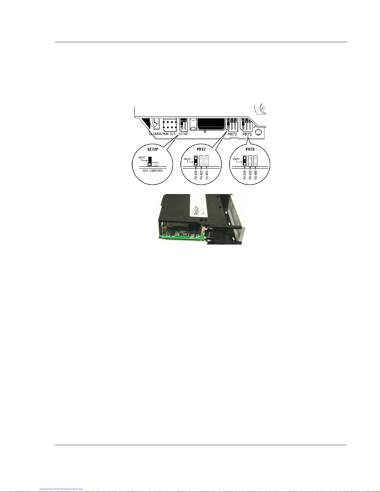
1.4 Setting Jumpers
If you use an interface other than RS-232 (default), you must change the jumper
configuration to select the interface you wish to use. There are three jumpers
located at the bottom of the module.
The following illustration shows the MVI56-DNP jumper configuration:
1 Set the PRT 2 (for application port 1) and PRT 3 (for application port 2)
jumpers select RS232, RS422, or RS485 to match the wiring needed for your
application. The default jumper setting for both application ports is RS-232.
2 The Setup Jumper acts as "write protection" for the module’s flash memory.
In "write protected" mode, the Setup pins are not connected, and the
module’s firmware cannot be overwritten. Do not jumper the Setup pins
together unless you are directed to do so by ProSoft Technical Support.
ProSoft Technology, Inc. Page 15 of 171
July 21, 2011
Page 16

Start Here MVI56-DNP ♦ ControlLogix Platform
User Manual DNP 3.0 Server
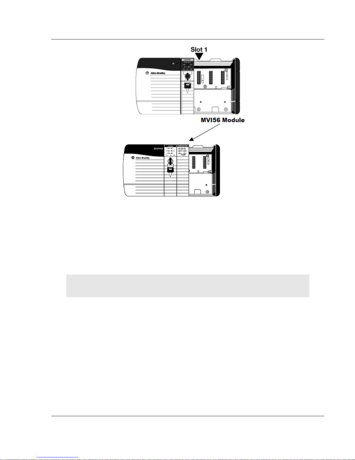
1.5 Installing the Module in the Rack
If you have not already installed and configured your ControlLogix processor and
power supply, please do so before installing the MVI56-DNP module. Refer to
your Rockwell Automation product documentation for installation instructions.
Warning: You must follow all safety instructions when installing this or any other electronic
devices. Failure to follow safety procedures could result in damage to hardware or data, or even
serious injury or death to personnel. Refer to the documentation for each device you plan to
connect to verify that suitable safety procedures are in place before installing or servicing the
device.
After you have checked the placement of the jumpers, insert MVI56-DNP into the
ControlLogix chassis. Use the same technique recommended by Rockwell
Automation to remove and install ControlLogix modules.
Warning: When you insert or remove the module while backplane power is on, an electrical arc
can occur. This could cause an explosion in hazardous location installations. Verify that power is
removed or the area is non-hazardous before proceeding. Repeated electrical arcing causes
excessive wear to contacts on both the module and its mating connector. Worn contacts may
create electrical resistance that can affect module operation.
1 Turn power OFF.
2 Align the module with the top and bottom guides, and slide it into the rack
until the module is firmly against the backplane connector.
Page 16 of 171 ProSoft Technology, Inc.
July 21, 2011
Page 17
MVI56-DNP ♦ ControlLogix Platform Start Here
DNP 3.0 Server User Manual
3 With a firm but steady push, snap the module into place.
4 Check that the holding clips on the top and bottom of the module are securely
in the locking holes of the rack.
5 Make a note of the slot location. You must identify the slot in which the
module is installed in order for the sample program to work correctly. Slot
numbers are identified on the green circuit board (backplane) of the
ControlLogix rack.
6 Turn power ON.
Note: If you insert the module improperly, the system may stop working, or may behave
unpredictably.
ProSoft Technology, Inc. Page 17 of 171
July 21, 2011
Page 18
Start Here MVI56-DNP ♦ ControlLogix Platform
User Manual DNP 3.0 Server
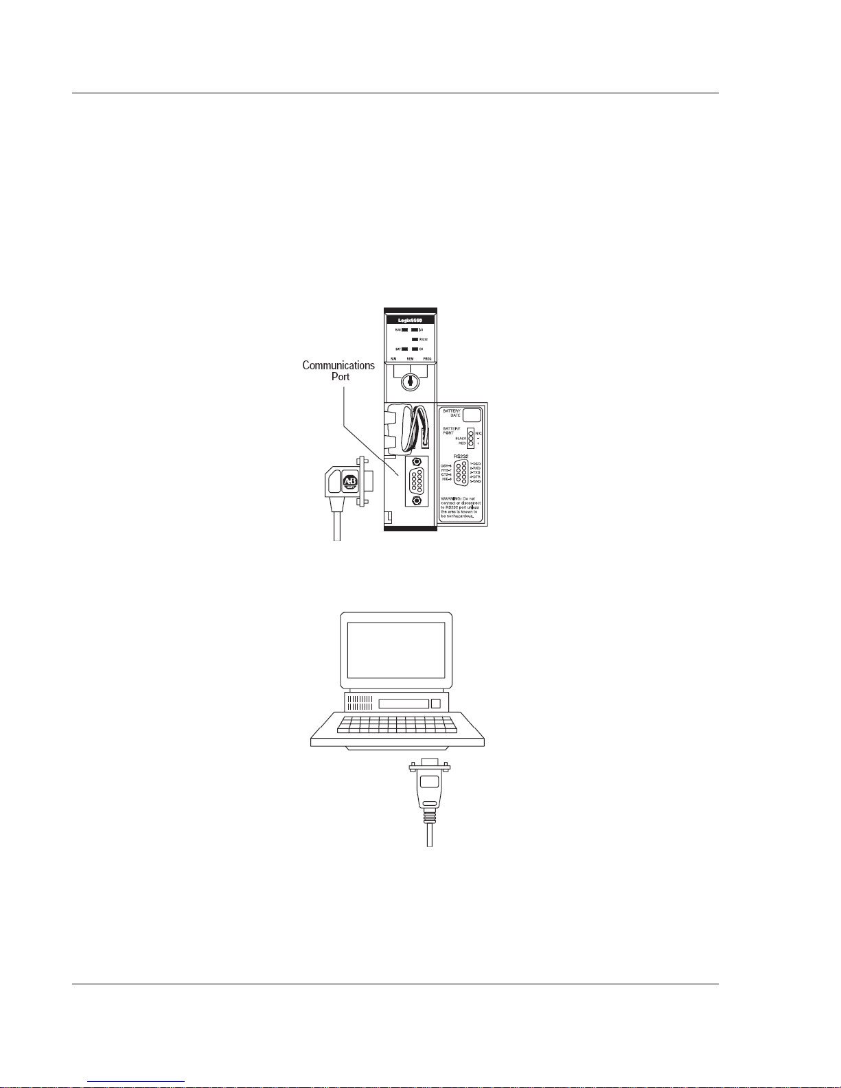
1.6 Connecting Your PC to the ControlLogix Processor
There are several ways to establish communication between your PC and the
ControlLogix processor. The following steps show how to establish
communication through the serial interface. It is not mandatory that you use the
processor's serial interface. You may access the processor through whatever
network interface is available on your system. Refer to your Rockwell Automation
documentation for information on other connection methods.
1 Connect the right-angle connector end of the cable to your controller at the
communications port.
2 Connect the straight connector end of the cable to the serial port on your
computer.
Page 18 of 171 ProSoft Technology, Inc.
July 21, 2011
Page 19

MVI56-DNP ♦ ControlLogix Platform Start Here
DNP 3.0 Server User Manual
1.7 Using the Sample Ladder Logic
The sample program for your MVI56-DNP module includes custom tags, data
types, and ladder logic for data I/O and status monitoring. For most applications,
you can run the sample ladder program without modification, or, for advanced
applications, you can incorporate the sample program into your existing
application.
The inRAx Solutions CD provides one or more versions of the sample ladder
logic. The version number appended to the file name corresponds with the
firmware version number of your ControlLogix processor. The firmware version
and sample program version must match.
1.7.1 Configuring the RSLinx Driver for the PC COM Port
If RSLogix is unable to establish communication with the processor, follow these
steps.
1 Open RSLinx.
2 Open the C
OMMUNICATIONS menu, and choose CONFIGURE DRIVERS.
This action opens the Configure Drivers dialog box.
ProSoft Technology, Inc. Page 19 of 171
July 21, 2011
Page 20

Start Here MVI56-DNP ♦ ControlLogix Platform
User Manual DNP 3.0 Server
Note: If the list of configured drivers is blank, you must first choose and configure a driver from the
Available Driver Types list. The recommended driver type to choose for serial communication with
the processor is RS-232 DF1 Devices.
3 Click to select the driver, and then click C
ONFIGURE. This action opens the
Configure RS-232 DF1 Devices dialog box.
4 Click the A
UTO-CONFIGURE button. RSLinx will attempt to configure your
serial port to work with the selected driver.
5 When you see the message Auto Configuration Successful, click the OK
button to dismiss the dialog box.
Note: If the auto-configuration procedure fails, verify that the cables are connected correctly
between the processor and the serial port on your computer, and then try again. If you are still
unable to auto-configure the port, refer to your RSLinx documentation for further troubleshooting
steps.
Page 20 of 171 ProSoft Technology, Inc.
July 21, 2011
Page 21
MVI56-DNP ♦ ControlLogix Platform Start Here
DNP 3.0 Server User Manual
1.7.2 Determining the Firmware Version of Your Processor
Important: The RSLinx service must be installed and running on your computer in order for
RSLogix to communicate with the processor. Refer to your RSLinx and RSLogix documentation for
help configuring and troubleshooting these applications.
1 Connect an RS-232 serial cable from the COM (serial) port on your PC to the
communication port on the front of the processor.
2 Start RSLogix 5000 and close any existing project that may be loaded.
3 Open the C
establish communication with the processor. This may take a few moments.
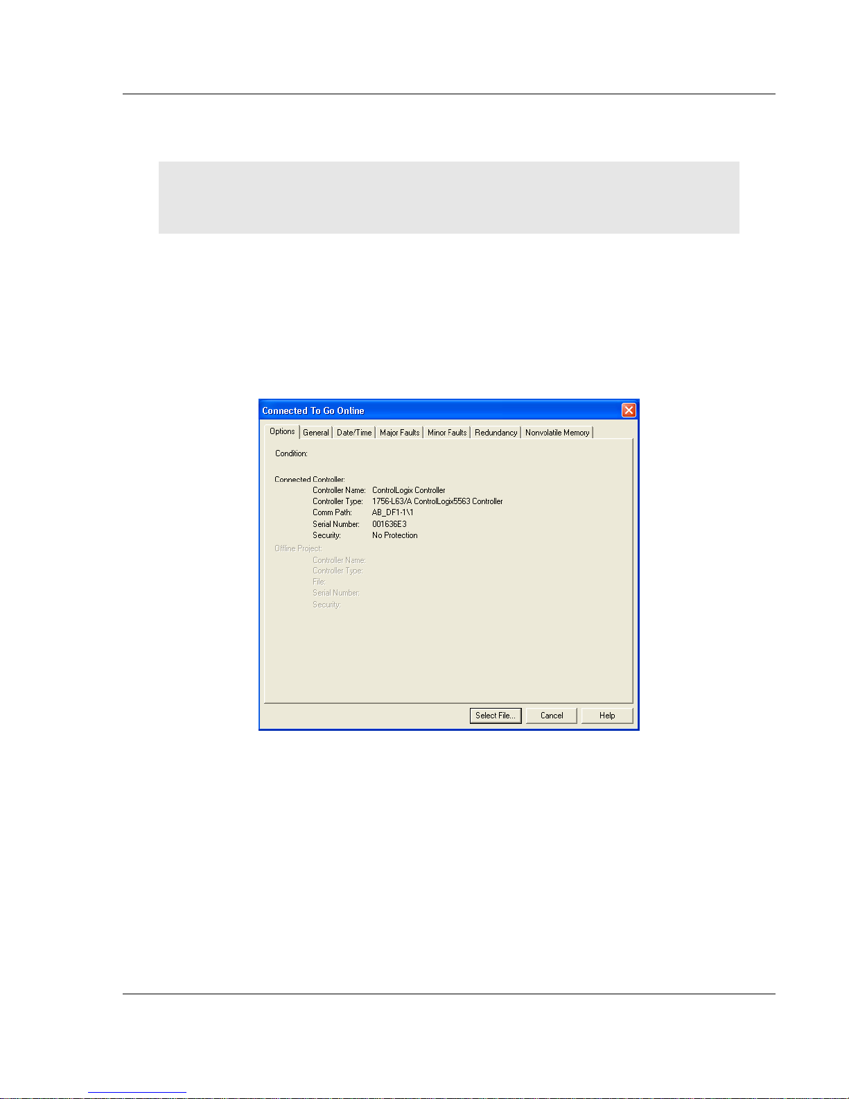
4 When RSLogix has established communication with the processor, the
Connected To Go Online dialog box will open.
OMMUNICATIONS menu and choose GO ONLINE. RSLogix will
ProSoft Technology, Inc. Page 21 of 171
July 21, 2011
Page 22
Start Here MVI56-DNP ♦ ControlLogix Platform
User Manual DNP 3.0 Server
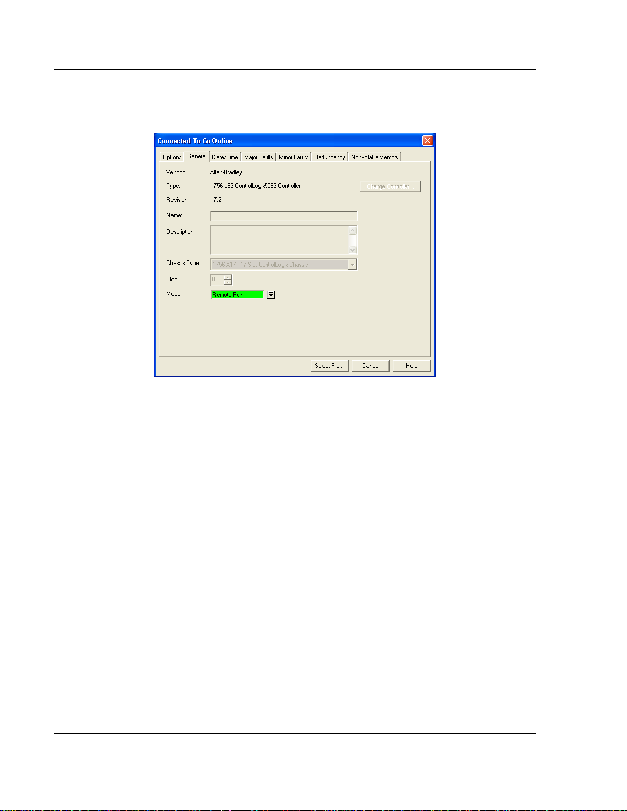
5 In the Connected To Go Online dialog box, click the GENERAL tab. This tab
shows information about the processor, including the Revision (firmware)
version. In the following illustration, the firmware version is 17.2.
Page 22 of 171 ProSoft Technology, Inc.
July 21, 2011
Page 23

MVI56-DNP ♦ ControlLogix Platform Start Here
DNP 3.0 Server User Manual
1.7.3 Adding the Module in Your Project
This topic describes how to add the module to your RSLogix 5000 project.
Note: The RSLogix 5000 software should be in "off-line" mode to add the module to a project.
Although some newer versions of RSLogix 5000 may allow new modules to be added while in
"online" mode, it is always considered safer to add new modules off-line and test the new
configuration in a test system before putting the modified program online.
This process consists of the following general steps.
1 Add the module to the project I/O configuration.
2 Select the sample ladder logic version that matches your processor firmware
version number and use it as a starting point for a new project or for copying
components into an existing project.
(Example ladder logic files are provided on the CD-ROM shipped with the
module or may be downloaded from the ProSoft Technology Web site.)
3 Modify the example ladder logic to meet the needs of your application, if
necessary.
4 Download the ladder logic to the processor.
Note: If you are installing this module in an existing application, you can copy the necessary
elements from the example ladder logic into your application.
The ladder logic samples show how to process one data block for each
supported data type, as well as showing how to use all of the special functions
and control variables used by the module. Depending on the point counts you
configure for each data type in the DNP.CFG file, the sample ladder logic may or
may not have sufficient data transfer capacity.
If your application has higher point counts than what is supported in the sample
ladder, you can add additional rungs with logic similar to that shown to process
data for up to two additional data blocks for each supported data type.
To Copy the Sample Ladder Logic into a New or an Existing Project
1 Add the MVI56-DNP module to the project.
In the C
ONTROLLER ORGANIZATION window, select I/O CONFIGURATION and
click the right mouse button to open a shortcut menu. On the shortcut menu,
choose N
EW MODULE...
ProSoft Technology, Inc. Page 23 of 171
July 21, 2011
Page 24
Start Here MVI56-DNP ♦ ControlLogix Platform
User Manual DNP 3.0 Server
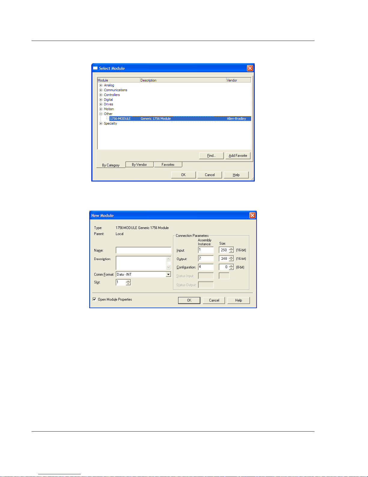
This action opens the SELECT MODULE dialog box.
2 Select the 1756-M
ODULE (GENERIC 1756 MODULE) from the list and click OK.
This action opens the NEW MODULE dialog box.
Page 24 of 171 ProSoft Technology, Inc.
July 21, 2011
Page 25
MVI56-DNP ♦ ControlLogix Platform Start Here
DNP 3.0 Server User Manual
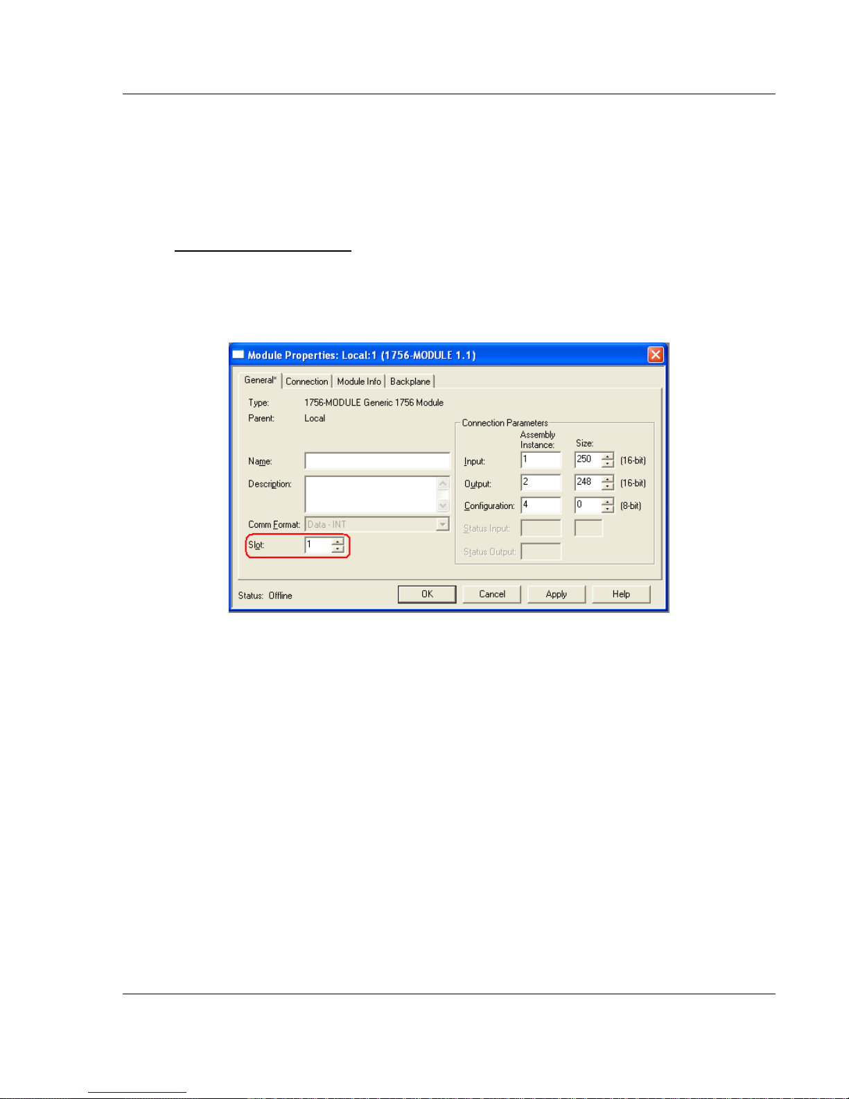
3 Set the Module Properties:
Parameter Value
Name Enter a module identification string. Example: DNP.
Description
Comm Format
Slot
Input Assembly Instance 1 (must use this value)
Input Size 250 (must use this value)
Output Assembly Instance 2 (must use this value)
Output Size 248 (must use this value)
Configuration Assembly Instance 4 (must use this value)
Configuration Size 0 (must use this value)
Enter a description for the module. Example: DNP 3.0
Server over Ethernet Communication Module
Select DATA-INT
Enter the slot number in the rack where the MVI56-DNP
module is located.
(no other option will work)
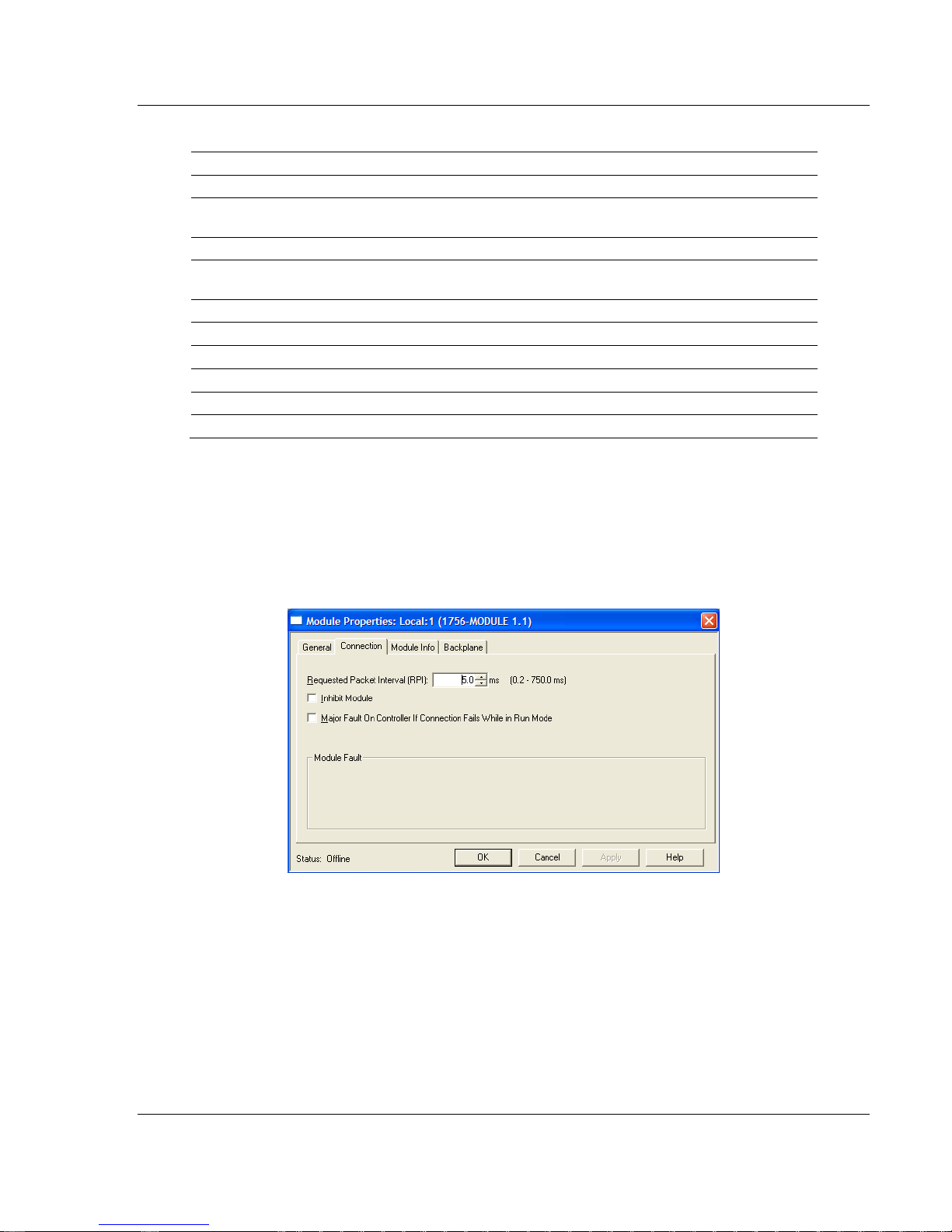
4 Select the Requested Packet Interval value for scanning the I/O on the
module. This value represents the minimum frequency the module will handle
scheduled events. This value should not be set to less than 1 millisecond.
Values between 1 and 10 milliseconds should work with most applications.
On the Connection tab, set the RPI value for your project. Click OK to
confirm.
ProSoft Technology, Inc. Page 25 of 171
July 21, 2011
Page 26

Start Here MVI56-DNP ♦ ControlLogix Platform
User Manual DNP 3.0 Server
After completing the module setup, the Controller Organization list will display
the module’s presence. The data required for the module will be defined to
the application, and objects will be allocated in the Controller Tags data area.
The following is an example of the Controller Organization list:
5 In a separate instance of RSLogix 5000, open the version of the sample
ladder logic project that matches the firmware revision number of your
ControlLogix processor. This is so you may copy and paste from the sample
into your existing project. If you are starting a new project, simply open the
appropriate sample version, pick your controller model and rack size, and use
this as the starting point for your new project.
6 Add the User Defined Data Types for the module. Copy these data types
from the sample ladder logic into your project. The Controller Organization list
should display the User Defined Data Types shown in the following example:
Page 26 of 171 ProSoft Technology, Inc.
July 21, 2011
Page 27
MVI56-DNP ♦ ControlLogix Platform Start Here
DNP 3.0 Server User Manual
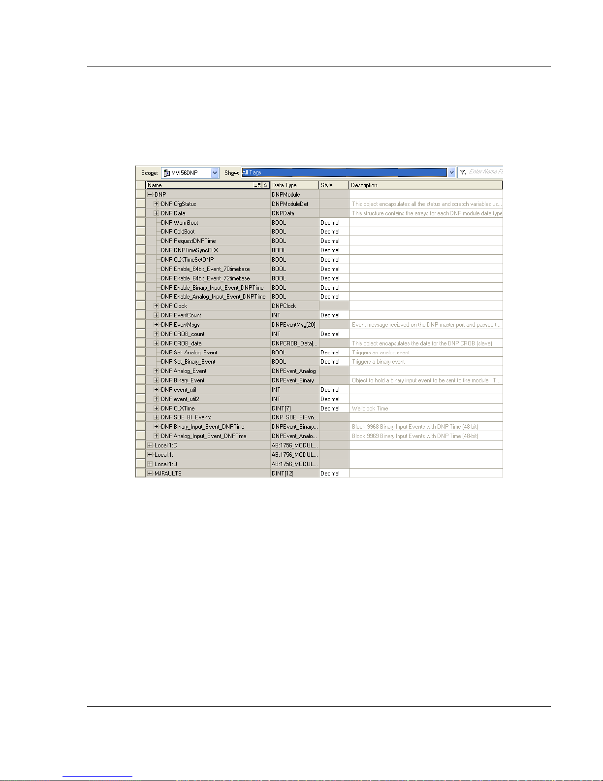
7 Add all controller tags. The MVI56-DNP module DNPCfgStatus tag array
holds the module status data. The DNPData tag array holds all the DNP and
IED data for each data type. Other more specialized tags and tag arrays hold
data to be sent or received by the Special Functions supported by the module
as well as bits and words used for sample ladder logic flow control and
processing (control bits and words).
ProSoft Technology, Inc. Page 27 of 171
July 21, 2011
Page 28

Start Here MVI56-DNP ♦ ControlLogix Platform
User Manual DNP 3.0 Server
8 The last step is to add the ladder logic. If you are using the sample ladder
logic, you may need to adjust it to fit your application. If you are not using the
ladder example, copy the ladder logic from the sample into your application
and make any modifications which may be needed for your application.
Page 28 of 171 ProSoft Technology, Inc.
July 21, 2011
Page 29
MVI56-DNP ♦ ControlLogix Platform Start Here
DNP 3.0 Server User Manual
1.7.4 Selecting the Slot Number for the Module
This sample application is for a module installed in Slot 1 in a ControlLogix rack.
The ladder logic uses the slot number to identify the module. If you are installing
the module in a different slot, you must update the ladder logic so that program
tags and variables are correct, and do not conflict with other modules in the rack.
To change the slot number
1 In the Controller Organization list, select the module and then click the right
mouse button to open a shortcut menu.
2 On the shortcut menu, choose P
Properties dialog box.
ROPERTIES. This action opens the Module
3 In the Slot
field, use the spinners on the right side of the field to select the slot
number where the module will reside in the rack, and then click OK.
RSLogix will automatically apply the slot number change to all tags, variables
and ladder logic rungs that use the MVI56-DNP slot number for computation.
ProSoft Technology, Inc. Page 29 of 171
July 21, 2011
Page 30
Start Here MVI56-DNP ♦ ControlLogix Platform
User Manual DNP 3.0 Server
1.8 Downloading the Sample Program to the Processor
Note: The key switch on the front of the ControlLogix processor must be in the REM or PROG
position.
1 If you are not already online with the processor, open the Communications
menu, and then choose DOWNLOAD. RSLogix 5000 will establish
communication with the processor. You do not have to download through the
processor's serial port, as shown here. You may download through any
available network connection.
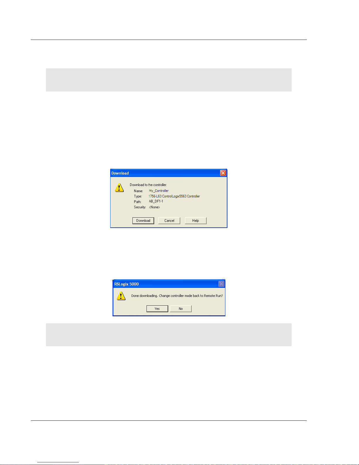
2 When communication is established, RSLogix 5000 will open a confirmation
dialog box. Click the D
processor.
OWNLOAD button to transfer the sample program to the
3 RSLogix 5000 will compile the program and transfer it to the processor. This
process may take a few minutes.
4 When the download is complete, RSLogix 5000 will open another
confirmation dialog box. If the key switch is in the REM position, click OK
switch the processor from PROGRAM
mode to RUN mode.
to
Note: If you receive an error message during these steps, refer to your RSLogix documentation to
interpret and correct the error.
Page 30 of 171 ProSoft Technology, Inc.
July 21, 2011
Page 31

MVI56-DNP ♦ ControlLogix Platform Start Here
DNP 3.0 Server User Manual
1.9 Connecting Your PC to the Module
With the module securely mounted, connect your PC to the
Configuration/Debug port using an RJ45-DB-9 Serial Adapter Cable and a Null
Modem Cable.
1 Attach both cables as shown.
2 Insert the RJ45 cable connector into the Config/Debug port of the module.
3 Attach the other end to the serial port on your PC.
The communication port driver in RSLinx can occasionally prevent other
applications from using the PC’s COM port. If you are not able to connect to the
module’s configuration/debug port using ProSoft Configuration Builder (PCB),
HyperTerminal or another terminal emulator, follow these steps to disable the
RSLinx driver.
1 Open RSLinx and go to C
OMMUNICATIONS > RSWHO.
2 Make sure that you are not actively browsing using the driver that you wish to
stop. The following shows an actively browsed network.
ProSoft Technology, Inc. Page 31 of 171
July 21, 2011
Page 32

Start Here MVI56-DNP ♦ ControlLogix Platform
User Manual DNP 3.0 Server
3 Notice how the DF1 driver is opened, and the driver is looking for a processor
on Node 1. If the network is being browsed, then you will not be able to stop
this driver. To stop the driver your RSWho screen should look like this:
Branches are displayed or hidden by clicking on the
or the icons.
4 When you have verified that the driver is not being browsed, go to
C
OMMUNICATIONS > CONFIGURE DRIVERS.
You may see something like this:
5 If you see the status as running, you will not be able to use this COM port for
anything other than communication to the processor. To stop the driver press
the S
TOP button on the side of the window:
6 After you have stopped the driver you will see the following.
Page 32 of 171 ProSoft Technology, Inc.
July 21, 2011
Page 33

MVI56-DNP ♦ ControlLogix Platform Start Here
DNP 3.0 Server User Manual
7 You may now use the COM port to connect to the Config/Debug port of the
module.
Note: You may need to shut down and restart your PC before it will allow you to stop the driver
(usually only on Windows NT machines). If you have followed all of the above steps, and it will not
stop the driver, then make sure you do not have RSLogix open. If RSLogix is open, you will not be
able to stop the DF1 driver. If RSLogix is not open, and you still cannot stop the driver, then reboot
your PC.
ProSoft Technology, Inc. Page 33 of 171
July 21, 2011
Page 34

Start Here MVI56-DNP ♦ ControlLogix Platform
User Manual DNP 3.0 Server
Page 34 of 171 ProSoft Technology, Inc.
July 21, 2011
Page 35

MVI56-DNP ♦ ControlLogix Platform Configuring the MVI56-DNP Module
DNP 3.0 Server User Manual
2 Configuring the MVI56-DNP Module
In This Chapter
Module Configuration File, DNP.CFG ................................................... 35
Using ProSoft Configuration Builder ...................................................... 48
2.1 Module Configuration File, DNP.CFG
In order for the module to operate, a configuration file (DNP.CFG) is required.
This configuration file contains all the information required to configure the
module’s Master drivers, set up the databases for the controlled devices and
establish a command list. Each parameter in the file must be set carefully in
order for the application to be implemented successfully.
The configuration file is separated into sections with topic header names
enclosed in the [ ] characters. Any record that begins with the "#" character is
considered to be a comment record. Any text to the right of a # character is
ignored by the program, and can be used to provide documentation within the
configuration file. Liberal use of comments within the file can ease the use and
interpretation of the data in the file.
The following topics describe each section of the configuration file.
Important: The configuration file must be named DNP.CFG, otherwise the configuration file will not
be recognized by the module.
Important: This module supports a maximum configuration file size of 128 kilobytes (131072
bytes). If the configuration file is larger than this size, the module will not accept the download. You
can reduce the size of the configuration file by opening the file in a text editor and removing
comment lines (lines preceded with the # character).
ProSoft Technology, Inc. Page 35 of 171
July 21, 2011
Page 36

Configuring the MVI56-DNP Module MVI56-DNP ♦ ControlLogix Platform
User Manual DNP 3.0 Server
2.1.1 MVI56-DNP Communication Module Configuration
[Section]/Item Range Description
[MODULE] General module configuration section
Module Name: 0 to 80
characters
Module Type: This parameter is fixed and not user-configurable.
[Section]/Item Range Description
[DNP Slave] DNP Slave configuration information
Internal Slave ID: 0 to 65534 This is the DNP address for the module. All messages with this address
Baud Rate: Baud rate
value
RTS On: 0 to 65535
milliseconds
RTS Off: 0 to 65535
milliseconds
Min Response Delay: 0 to 65535
milliseconds
Modem: Yes or No This parameter defines if a dial-up modem is used on the secondary
Connect Timeout: 0 to 65535 Defines the number of milliseconds to wait for the CD signal to be set
First Character Delay: 0 to 65535 Defines the number of milliseconds to wait before sending the first
Redial Delay Time: 0 to 32000 Defines the minimum number of milliseconds to wait before a redial
Redial Random Delay: 0 to 32000 Defines a random millisecond time range to be added to the redial delay
Idle Timeout: 0 to 65535 Defines the number of milliseconds the modem is inactive before it will
Phone Number: ASCII String
Data
Collision Avoidance: Yes or No This parameter defines if collision avoidance will be utilized on the
CD Idle Time: 0 to 32000 Defines the minimum number of milliseconds to wait before transmitting
CD Random Time: 0 to 32000 Defines the range of random time to be added to the CD Idle Time
This parameter assigns a name to the module that can be viewed using
the configuration/debug port. Use this parameter to identify the module
and the configuration file.
It identifies the module type when a DNP.CFG file is imported in ProSoft
Configuration Builder (PCB).
from the master will be processed by the module.
Primary DNP Port Baud Rate: 300, 600, 1200, 2400, 4800, 9600,
19200, 384 (38400), 576 (57600), 115 (115200)
This value represents the number of 1 ms increments to be inserted
between asserting the RTS modem line and the actual transmission of
the data.
This value represents the number of 1 ms increments to be inserted
after the last character of data is transmitted before the RTS modem line
is dropped.
Minimum time between receiving a request and transmitting a response.
Allows Master time to disable transmitter on an RS-485 network.
DNP slave port. A modem cannot be used if the port is configured as a
Master.
high. The CD signal indicates a connection is made using a dial-up
modem.
message after the connection is first made. This delay only applies to
the first packet sent to the modem.
attempt is made by the slave.
time before the modem is accessed.
disconnect.
This field contain a null-terminated, ASCII character string used by the
dial-up modem. The string must contain all characters required by the
modem. An example string is ATDT1800222333. Maximum length is 34
bytes including the terminating 0.
primary DNP slave port.
a message after the CD signal is recognized as low.
before a message will be transmitted from the slave.
Page 36 of 171 ProSoft Technology, Inc.
July 21, 2011
Page 37

MVI56-DNP ♦ ControlLogix Platform Configuring the MVI56-DNP Module
DNP 3.0 Server User Manual
[Section]/Item Range Description
CD Time Before Receive: 0 to 65535 Defines the number of milliseconds to wait before receiving characters
after the CD signal is recognized as high.
BI Class: 0 to 3 This parameter specifies the default class to be utilized for all the binary
input points in the DNP database that are not defined in the override list
section.
AI Class: 0 to 3 This parameter specifies the default class to be utilized for all the analog
input points in the DNP database that are not defined in the override list
section.
Float Class: 0 to 3 This parameter specifies the default class to be utilized for all the
floating-point input points in the DNP database that are not defined in
the override list section.
Double Class: 0 to 3 This parameter specifies the default class to be utilized for all the double
floating-point input points in the DNP database that are not defined in
the override list section.
AI Deadband: 0 to 32767 This parameter specifies the default deadband value assigned to all
points not defined in the override list for the analog input point type in
the DNP database.
Float Deadband: 0 to
maximum
float value
Double Deadband: 0 to
maximum
double value
Select/Operate Arm Time: 1 to 65535
milliseconds
Write Time Interval: 0 to 1440
minutes
Data Link Confirm Mode: Coded Value
(N=Never,
S=Sometime
s, A=Always)
Data Link Confirm Tout:
(Tout = Timeout)
Data Link Max Retry: 0 to 255
App Layer Confirm Tout: 1 to 65535
Unsolicited Response: Yes or No Set if the slave unit will send unsolicited response messages. If set to
Class 1 Unsol Resp Min: 1 to 255
Class 2 Unsol Resp Min: 1 to 255
1 to 65535
milliseconds
retries
milliseconds
events
events
This parameter specifies the default deadband value assigned to all
points not defined in the override list for the floating-point input point
type in the DNP database.
This parameter specifies the default deadband value assigned to all
points not defined in the override list for the double floating-point input
point type in the DNP database.
Time period after select command received in which operate command
will be performed. After the select command is received, the operate
command will only be honored if it arrives within this period of time.
Time interval to set the need time IIN bit (0=never), which will cause the
Master to write the time. Stored in milliseconds in the module memory.
IED can request acknowledgement from Master station when sending
data. The codes are as follows: 0=Never, 1=Sometimes, 2=Always
Time period to wait for Master Data Link confirmation of last frame sent.
This time is in milliseconds. This parameter is only used if the frame is
sent with confirmation requested.
Maximum number of retries at the Data Link level to obtain a
confirmation. If this value is set to 0, retries are disabled at the data link
level of the protocol. This parameter is only used if the frame is sent with
confirmation requested.
Event data contained in the last response may be sent again if not
confirmed within the millisecond time period set. If application layer
confirms are used with data link confirms, ensure that the application
layer confirm timeout is set long enough.
No, the slave will not send unsolicited responses. If set to Yes, the slave
will send unsolicited responses.
Minimum number of events in Class 1 required before an unsolicited
response will be generated.
Minimum number of events in Class 2 required before an unsolicited
response will be generated.
ProSoft Technology, Inc. Page 37 of 171
July 21, 2011
Page 38

Configuring the MVI56-DNP Module MVI56-DNP ♦ ControlLogix Platform
User Manual DNP 3.0 Server
[Section]/Item Range Description
Class 3 Unsol Resp Min: 1 to 255
events
Unsol Resp Delay: 0 to 65535
milliseconds
Uresp Master Address: 0 to 65534 DNP destination address where unsolicited response messages are
Uresp Retry Count: 0 to 255
retries
AI Events with time: Yes or No This parameter sets if the analog input events generated by the module
Time Sync Before Events: Yes or No This parameter determines if events are to be generated by the module
Initialize DNP Database: Y or N This parameter determines if the module will request data from the
Pass-Through CROB Y or N This parameter will pass CROB functions through to the Ladder Logic.
Use Trip/Close Single Point Y or N Used for backward-compatibility with older MVI56-DNP modules. If Y
[Section]/Item Range Description
[DNP Slave Database] DNP Slave Database definition
Binary Inputs: 0 to 8000
points
PLC Binary Inputs: 0 to 8000
points
Analog Inputs: 0 to 500
points
PLC Analog Inputs: 0 to 500
points
Float Inputs: 0 to 250
points
PLC Float Inputs: 0 to 250
points
Double Inputs: 0 to 125
points
PLC Double Inputs: 0 to 125
points
Minimum number of events in Class 3 required before an unsolicited
response will be generated.
Maximum number of 1 millisecond intervals to wait after an event occurs
before sending an unsolicited response message. If set to 0, only use
minimum number of events.
sent.
Determines the number of unsolicited message retries sent on primary
DNP port before changing to secondary port. If the value is 0, port
switching will be disabled.
will include the date and time of the event. If the parameter is set to No,
the default is set to no time data. If the parameter is set to Yes, the
default object will include the time of the event.
before the time synchronization from the Master unit. If the parameter is
set to No, no events will be generated until the module's time has been
synchronized. If the parameter is set to Yes, events will always be
generated.
processor to initialize the DNP database output data areas. If this option
is utilized, ladder logic is required to send the requested block from the
processor to the module.
Block 9910 wil be sent to the CLX processor with the data received for
Trip/Close or Pulse CROB functions from an attached DNP Master.
(Yes), will cause Trip/Close operations to use a single point operation.
Number of digital input points to configure in the DNP slave device.
Each point will be stored as a single bit in the module memory.
Number of digital input points configured above that are to be obtained
from the ControlLogix processor. All other binary input points must come
from the attached IED units.
Number of analog input points to configure in the DNP slave device.
Each point will occupy a one word area in the module memory.
Number of analog input points configured above that are to be obtained
from the ControlLogix processor. All other analog input points must
come from the attached IED units.
Number of floating-point input points to configure in the DNP slave
device. Each point will occupy a two-word area in the module memory.
Number of floating-point input points configured above that are to be
obtained from the PLC.
Number of double floating-point input points to configure in the DNP
slave device. Each point will occupy a four-word area in the module
memory.
Number of double floating-point input points configured above that are
to be obtained from the ControlLogix processor.
Page 38 of 171 ProSoft Technology, Inc.
July 21, 2011
Page 39

MVI56-DNP ♦ ControlLogix Platform Configuring the MVI56-DNP Module
DNP 3.0 Server User Manual
[Section]/Item Range Description
Counters: 0 to 250
points
PLC Counters: 0 to 250
points
Binary Outputs: 0 to 8000
points
PLC Binary Outputs: 0 to 8000
points
Analog Outputs: 0 to 500
points
PLC Analog Outputs: 0 to 500
points
Float Outputs: 0 to 250
points
PLC Float Outputs: 0 to 250
points
Double Outputs: 0 to 125
points
PLC Double Outputs: 0 to 125
points
Number of counter points to configure in the DNP slave device. Each
point will occupy a two word area in the module memory. This number
corresponds to the number of frozen counters. The application maps the
counters to the frozen counters directly.
Number of counter points configured above that are to be obtained from
the ControlLogix processor. All other counter points must come from the
attached IED units.
Number of digital output points to configure in the DNP slave device.
Each point will be stored as a single bit in the module memory.
Number of digital output points configured above that are to be sent to
the ControlLogix processor. All other binary output points will be sent to
the attached IED units.
Number of analog output points to configure in the DNP slave device.
Each point will occupy a one word area in the module memory.
Number of analog output points configured above that are to be sent to
the ControlLogix processor. All other analog output points will be sent to
the attached IED units.
Number of floating-point output points to configure in the DNP slave
device. Each point will occupy a two- word area in the module memory.
Number of floating-point output points configured above that are to be
sent to the ControlLogix.
Number of double floating-point output points to configure in the DNP
slave device. Each point will occupy a four-word area in the module
memory.
Number of double floating-point output points configured above that are
to be sent to the ControlLogix processor.
[Section]/Item Description
[DNP Slave Binary Inputs] DNP database binary input override values
# This area is to override the class assignment for binary input database
points. Enter list of points between the START and END labels.
#
# Point# Class
START
END
[Section]/Item Description
[DNP Slave Analog Inputs] DNP database analog input override values
START
# This area is to override the class and deadband assignment for analog
input database points. Enter list of points between the START and END
labels.
#
# Point# Class Deadband
START
END
ProSoft Technology, Inc. Page 39 of 171
July 21, 2011
Page 40

Configuring the MVI56-DNP Module MVI56-DNP ♦ ControlLogix Platform
User Manual DNP 3.0 Server
[Section]/Item Description
[DNP Slave Float Inputs] DNP database floating-point input override values
# This area is to override the class and deadband assignment for float
input database points. Enter list of points between the START and END
labels.
#
# Point# Class Deadband
START
END
[Section]/Item Description
[DNP Slave Double Inputs] DNP database double floating-point input override values
# This area is to override the class and deadband assignment for double
input database points. Enter list of points between the START and END
labels.
#
# Point# Class Deadband
START
END
[Section]/Item Range Description
[Secondary Port] Definitions for secondary port on module
Type: M or S or
blank
Baud Rate: Baud rate
value
RTS On: 0 to 65535
millisecond
s
RTS Off: 0 to 65535
millisecond
s
Min Response Delay: 0 to 65535
millisecond
s
Collision Avoidance: Yes or No This parameter defines if collision avoidance will be utilized on the
CD Idle Time: 0 to 32000 Defines the minimum number of milliseconds to wait before
CD Random Time: 0 to 32000 Defines the range of random time to be added to the CD Idle Time
CD Time Before Receive: 0 to 65535 Defines the number of milliseconds to wait before receiving
This parameter defines the functionality of the secondary port on the
module.
M = emulate a DNP Master port
S = back-up DNP slave port to the primary port.
Any other value will disable the port.
Secondary DNP Port Baud Rate: 300, 600, 1200, 2400, 4800, 9600,
19200, 384 (38400), 576 (57600), 115 (115200)
This value represents the number of 1 ms increments to be inserted
between asserting the RTS modem line and the actual transmission
of the data.
This value represents the number of 1 ms increments to be inserted
after the last character of data is transmitted before the RTS modem
line is dropped.
Minimum time between receiving a request and transmitting a
response. Allows Master time to disable transmitter on an RS-485
network.
primary DNP slave port.
transmitting a message after the CD signal is recognized as low.
before a message will be transmitted from the slave.
characters after the CD signal is recognized as high.
Page 40 of 171 ProSoft Technology, Inc.
July 21, 2011
Page 41

MVI56-DNP ♦ ControlLogix Platform Configuring the MVI56-DNP Module
DNP 3.0 Server User Manual
[Section]/Item Range Description
[DNP Master] Definitions for DNP Master port if utilized.
Internal ID:
Initialize IED Database:
Event Messages to PLC:
Use IED BO Read Data
Use IED AO Read Data
0 to
65534
Yes or
No
Yes or
No
Yes or
No
Yes or
No
This is the DNP address for the module. All messages
with this address from the Master will be processed by
the module.
This parameter determines if the module will request
data from the processor to initialize the IED database
input data areas. If this option is utilized, ladder logic is
required to send the requested block from the processor
to the module.
This parameter determines if event messages received
on the Master port will be sent to the processor. If this
option is utilized, ladder logic must handle the 9903
blocks generated by the module.
This parameter determines whether or not the IED BO
Read data will be stored in the database (default = No).
This parameter determines whether or not the IED AO
Read data will be stored in the database (default = No).
[Section]/Item Range Description
[IED Database] Database definition for DNP Master port if utilized
Binary Inputs:
Analog Inputs:
Counters:
Binary Outputs:
Analog Outputs:
0 to 8000
points
0 to 500
points
0 to 250
points
0 to 8000
points
0 to 500
points
Number of binary input points contained in the IED
database to transfer to the ControlLogix processor and
obtained from the attached IED units..
Number of analog input points contained in the IED
database to transfer to the ControlLogix processor and
obtained from the attached IED units..
Number of counter points contained in the IED database
to transfer to the ControlLogix processor and obtained
from the attached IED units..
Number of binary output points contained in the IED
database which are transferred from the ControlLogix
processor and used by the attached IED units..
Number of analog output points contained in the IED
database which are transferred from the ControlLogix
processor and used by the attached IED units..
[Section]/Item Description
[DNP Master Slave List]
ProSoft Technology, Inc. Page 41 of 171
July 21, 2011
Definition of the IED units to communicate with the DNP
Master port, if utilized
Page 42

Configuring the MVI56-DNP Module MVI56-DNP ♦ ControlLogix Platform
User Manual DNP 3.0 Server
[Section]/Item Description
# This section stores information about each slave to be used by the Master port. There must be
an entry in this table for each node to be used in the command list. Two of the parameters in this
list are coded values:
# Conf Mode 0=Never, 1=Sometimes and 2=Always (select 0)
# Flags is bit coded as follows:
# Bit 0 (decimal 1) Enable the slave
# Bit 1 (decimal 2) Use Unsolicited messaging with this slave
# Bit 2 (decimal 4) Use delay measurement with this slave
# Bit 3 (decimal 8) Auto time synchronization enabled
#
# Node DL Conf Conf Conf App Rsp
# Address Mode Timeout Retry Timeout Flags
START
END
[Section]/Item Description
[DNP Master Commands]
# This section contains the list of commands to process on the Master port.
# Node addresses present in the command list must have an entry in the
#DNP Slave List]. Commands with nodes not present in the list will not be
# executed.
# 1 2 3 4 5 6 7 8 9 10
#Flags/ Node Data Data Cmd Device Point DNP DB IED DB Poll
#Enable Address Object Variation Func Address Count Address Address interval
START
END
Definition of the commands to be issued to the IED
units by the DNP Master port.
Page 42 of 171 ProSoft Technology, Inc.
July 21, 2011
Page 43

MVI56-DNP ♦ ControlLogix Platform Configuring the MVI56-DNP Module
DNP 3.0 Server User Manual
2.1.2 Slave List
The slave list defines the IED units and their specific communication parameters
for a DNP Master port. Up to 40 IED units can be defined in the module to be
associated with the Master port. The structure of each row in the list is described
in the following table.
Column Variable Name Data Range Description IF Error
1
2
3
4
5
DNP Slave
Address
Data Link
Confirm Mode
Data Link
Confirm Timeout
Maximum
Retries for Data
Link Confirm
Application
Layer Response
Time-out
0 to 65534
Coded Value
(0=Never,
1=Sometimes,
2=Always)
1 to 65535
milliseconds
0 to 255 retries
1 to 65535
milliseconds
This is the slave address for the
unit to override the default values.
This value specifies if data link
frames sent to the remote device
require a data link confirm. This
value should always be set to zero
for almost all applications.
This parameter specifies the time
to wait for a data link confirm from
the remote device before a retry is
attempted.
Maximum number of retries at the
Data Link level to obtain a
confirmation. If this value is set to
0, retries are disabled at the data
link level of the protocol. This
parameter is only used if the frame
is sent with confirmation requested.
Time-out period the Master will wait
for each response message
fragment. If data link confirms are
enabled, make sure the time-out
period is set long enough to permit
all data confirm retries.
Ignore
0
300
3
5000
ProSoft Technology, Inc. Page 43 of 171
July 21, 2011
Page 44

Configuring the MVI56-DNP Module MVI56-DNP ♦ ControlLogix Platform
User Manual DNP 3.0 Server
Column Variable Name Data Range Description IF Error
6 Slave Mode Coded Value
(Bit-mapped)
Bit 0=Enable
Bit 1=Unsol Msg
Bit 2=Use DM
Bit 3=Auto Time
Sync
This word contains bits that define
the slave mode. The slave mode
defines the functionality of the
slave device and can be combined
in any combination.
The fields have the following
definitions:
Bit 0 ENABLE:
Determines if this slave will be
used.
UNSOL MSG:
Causes an enabled unsolicited
response message to be sent to
the slave when its RESTART IIN bit
is set. This parameter is also
required for unsolicited message
reporting by the IED unit.
USE DM:
Uses delay measurement.
AUTO TIME S YNC:
Time synchronization used when
NEED TIME IIN bit set.
5
Page 44 of 171 ProSoft Technology, Inc.
July 21, 2011
Page 45

MVI56-DNP ♦ ControlLogix Platform Configuring the MVI56-DNP Module
DNP 3.0 Server User Manual
2.1.3 Command List
The command list stores the commands to be used by the DNP Master port. This
list must be defined only if the DNP Master port is used. Up to 300 commands
can be defined for the Master port. The structure of each row in the list is shown
in the following table.
Word Offset Definitions
0 Port/Flags
1 Slave Address
2 Object
3 Variation
4 Function
5 Address in Slave
6 Point Count
7 DNP DB Address
8 IED DB Address
9 Poll Interval
Port Flags
Bits in the Port/Flags parameter are dependent on the data type.
For Binary Input, Analog Input and Counter data points:
Port/Flags Bits Description Decimal Equivalent
0 to 1 Communication port (0=Internal, 2=Port 2 [Master]) 0 or 2
2 Enable/Disable Command (1=Enable, 0=Disable) 4
3 RBE Flag(1=Events from IED, 0=Events by module) 8
4 to 7 Not Used
For these data types, the qualifier used in the data request depends on the Point
Count and Address in Slave fields in the command as follows:
If Point Count < 0, then use Qualifier 06h (All points, packed & -Point Count = #
of points to consider)
If Address in Slave = 0 & Point Count > 0, then use Qualifier 00h or 01h (points 0
to Point Count -1)
If Address in Slave > 0 & Point Count > 0, then use Qualifier 00h or 01h (Address
in Slave to Address in Slave + Point Count -1)
ProSoft Technology, Inc. Page 45 of 171
July 21, 2011
Page 46

Configuring the MVI56-DNP Module MVI56-DNP ♦ ControlLogix Platform
User Manual DNP 3.0 Server
For Binary Output and Analog Output points:
Port/Flags Bits Description Decimal Equivalent
0 to 1 Communication port (0= I nternal, 2=Port 2) 0 or 2
2 Enable/Disable Command (1=Enable, 0=Disable) 4
3 Poll Type (0=Poll, 1=Exception) 8
4 Data Source(0=DNP Database, 1=IED Database) 16
5 to 7 Not Used
For these data types the qualifier used in the data request depends on the Point
Count and Address in Slave fields in the command as follows:
If Address in Slave = 0 & Point Count > 0, then use Qualifier 17h or 28h (Point
Count specified starting at point 0)
If Address in Slave > 0 & Point Count > 0, then use Qualifier 17h or28h (points
from Address in Slave to Address in Slave + Point Count -1)
If Point Count <= 0, then ignore because this is illegal for outputs.
Slave Address
This parameter specifies the Slave Address of the IED device on the DNP
network to which the command will be sent. The parameter has a range of 0 to
65535. The value of 65535 is reserved for broadcast messages. Verify that the
slave configuration information is set up in the module for each slave defined in
the command list.
Object
This parameter specifies the DNP Object type in the command. Valid Objects for
the module are 1, 2, 10, 12, 20, 21, 30, 32, 40, 41, 50, 60 and 80. A value of 0 is
permitted in this field for a set of special commands.
Variation
This parameter is specific to the object type selected.
Function
This parameter specifies the DNP Function for the command list Object. The
Object type determines the value of the Functions permitted. For example, the
only Function permitted for Binary Input data points is the R
EAD FUNCTION
(FUNCTION CODE 1). For Counter and Output Objects, more functions are
available.
Address In Slave
This value must be greater than or equal to zero. If it is set to a value less than
zero, the command will be ignored. This parameter specifies the starting point
address in the IED unit.
Page 46 of 171 ProSoft Technology, Inc.
July 21, 2011
Page 47

MVI56-DNP ♦ ControlLogix Platform Configuring the MVI56-DNP Module
DNP 3.0 Server User Manual
Point Count
This parameter defines the number of points in the IED unit that will be affected
by the command. Refer to the discussion in the Command List topic, above, to
interpret this parameter’s meaning for the different Object types.
DNP DB Address
This parameter defines the starting point address in the DNP database for the
command. If the parameter has a value of -1, the DNP database is not used with
the point.
IED DB Address
This parameter defines the starting point address in the IED database for the
command. If the parameter has a value of -1, the IED database is not used with
the point.
Poll Interval
This parameter specifies the minimum frequency at which the module should
execute the command. The value is entered in units of seconds. For example, to
execute a command every 10 seconds, enter a value of 10 in this field. A value of
0 for the parameter implies that the command should be executed every scan of
the list, as often as possible.
ProSoft Technology, Inc. Page 47 of 171
July 21, 2011
Page 48

Configuring the MVI56-DNP Module MVI56-DNP ♦ ControlLogix Platform
User Manual DNP 3.0 Server
2.2 Using ProSoft Configuration Builder
ProSoft Configuration Builder (PCB) provides a convenient way to manage
module configuration files customized to meet your application needs. PCB is not
only a powerful solution for new configuration files, but also allows you to import
information from previously installed (known working) configurations to new
projects.
2.2.1 Setting Up the Project
To begin, start PROSOFT CONFIGURATION BUILDER (PCB).
If you have used other Windows configuration tools before, you will find the
screen layout familiar. PCB’s window consists of a tree view on the left, and an
information pane and a configuration pane on the right side of the window. When
you first start PCB, the tree view consists of folders for Default Project and
Default Location, with a Default Module in the Default Location folder. The
following illustration shows the PCB window with a new project.
Page 48 of 171 ProSoft Technology, Inc.
July 21, 2011
Page 49

MVI56-DNP ♦ ControlLogix Platform Configuring the MVI56-DNP Module
DNP 3.0 Server User Manual
Adding the MVI56-DNP module to the project
1 Use the mouse to select D
EFAULT MODULE in the tree view, and then click the
right mouse button to open a shortcut menu.
2 On the shortcut menu, choose C
HOOSE MODULE TYPE. This action opens the
Choose Module Type dialog box.
3 In the Product Line Filter area of the dialog box, select MVI56. In the Select
Module Type dropdown list, select MVI56-DNP, and then click OK
to save
your settings and return to the ProSoft Configuration Builder window.
ProSoft Technology, Inc. Page 49 of 171
July 21, 2011
Page 50

Configuring the MVI56-DNP Module MVI56-DNP ♦ ControlLogix Platform
User Manual DNP 3.0 Server
2.2.2 Renaming PCB Objects
Notice that the contents of the information pane and the configuration pane
changed when you added the module to the project.
At this time, you may wish to rename the Default Project and Default Location
folders in the tree view.
1 Select the object, and then click the right mouse button to open a shortcut
menu. From the shortcut menu, choose R
ENAME.
2 Type the name to assign to the object.
3 Click away from the object to save the new name.
Configuring Module Parameters
1 Click the [+] sign next to the module icon to expand module information.
2 Click the
[+] sign next to any icon to view module information and
configuration options.
3 Double-click any
icon to open an Edit dialog box.
4 To edit a parameter, select the parameter in the left pane and make your
changes in the right pane.
5 Click OK
to save your changes.
Page 50 of 171 ProSoft Technology, Inc.
July 21, 2011
Page 51

MVI56-DNP ♦ ControlLogix Platform Configuring the MVI56-DNP Module
DNP 3.0 Server User Manual
Creating Optional Comment Entries
1 Click the [+] to the left of the
icon to expand the module
comments.
2 Double-click the
icon. The Edit - Module Comment dialog box
appears.
3 Enter your comment and click OK
to save your changes.
Printing a Configuration File
1 Select the module
icon, and then click the right mouse button to open a
shortcut menu.
2 On the
shortcut menu, choose VIEW CONFIGURATION. This action opens the
View Configuration window.
3 In the View Configuration window, open the F
ILE menu, and choose PRINT.
This action opens the Print dialog box.
4 In the Print dialog box, choose the printer to use from the drop-down list,
select printing options, and then click OK.
ProSoft Technology, Inc. Page 51 of 171
July 21, 2011
Page 52

Configuring the MVI56-DNP Module MVI56-DNP ♦ ControlLogix Platform
User Manual DNP 3.0 Server
Page 52 of 171 ProSoft Technology, Inc.
July 21, 2011
Page 53

MVI56-DNP ♦ ControlLogix Platform Ladder Logic
DNP 3.0 Server User Manual
3 Ladder Logic
In This Chapter
DNP Module .......................................................................................... 54
Module Data Objects ............................................................................. 55
Special Data Objects ............................................................................. 62
Ladder logic is required for the MVI56-DNP module to work. Tasks that must be
handled by the ladder logic are module data transfer, special block handling, and
status data receipt. Additionally, a power-up handler may be needed to handle
the initialization of the module’s data and to clear any processor fault conditions.
The sample ladder logic, on the inRAx CD-ROM, is extensively commented, to
provide information on the purpose and function of each rung. For most
applications, the sample ladder will work without modification.
ProSoft Technology, Inc. Page 53 of 171
July 21, 2011
Page 54

Ladder Logic MVI56-DNP ♦ ControlLogix Platform
User Manual DNP 3.0 Server
3.1 DNP Module
The sample ladder logic relies heavily on the use of User-defined Data Types
(UDTs) to help group and structure the wide variety and volume of data and
control features the module offers. Lower-order UDT structures are often
embedded in higher-order structures to help further organize data into more
easily understood data collections.
All data and control parameters related to the MVI56-DNP are contained in
twenty-one (21) User-defined Data Types (UDTs). The DNPModule UDT is the
primary, top level data structure in which all other lower-order data types are
grouped and organized. All groups branch down from this UDT.
To utilize all the features and functions of the module, an instance of each data
type is required. This is accomplished by declaring controller tag variables using
these data types in the Controller Tags Edit Tags dialog box. You can start with
the sample ladder logic and build your application around the sample; or, you can
duplicate the I/O Configuration, UDTs, Controller Tags, and Ladder Logic (Tasks)
from the sample program into your existing application project.
Some UDTs hold process or status data (Module Data Objects). This data can be
monitored and manipulated by your application-specific ladder logic program.
Other UDTs are used to store and organize the parameters needed for special
functions and control features (Special Data Objects). All of these data types will
be discussed in more detail in succeeding topics.
Page 54 of 171 ProSoft Technology, Inc.
July 21, 2011
Page 55

MVI56-DNP ♦ ControlLogix Platform Ladder Logic
DNP 3.0 Server User Manual
3.2 Module Data Objects
These objects hold process and status data values. All supported DNP data
types have their own UDTs and controller tags. This makes it much easier to
identify and use the various data types.
3.2.1 DNPModuleDef Object
The DNPModuleDef object contains all the MVI56-DNP module status data.
Name Style Description
GenStat DNPSlvStat General status information
ErrList INT[60] Decimal List of last 60 slave errors
IINSlaveBits INT[40] IIN Bits received from slaves
BP DNPBackplane Data to handle backplane logic
This object contains lower-order objects that organize and structure status data
from the module. The ErrList member of this object stores a list of the 60 most
recent slave errors generated by the module. This data is passed to the
processor from the module by Read Block 100. Ladder logic transfers this
information from the backplane transfer block into the ErrList controller tag array.
Read Block 100 is also used to move the slaves' Internal Indication (IIN) bits
(status and error flag bits) from the module to the processor. These bits are used
by the slaves to report status and error information to the module's DNP Master
driver. Ladder logic transfers this data from backplane transfer Block 100 into the
IINSlaveBits controller tag array. The relationship of which slave relates to which
word in the table is determined by the order in which slaves are listed in the DNP
Master Slave List in the configuration file, regardless of their slave ID number on
the DNP network.
DNP Master Slave List Position IINSlaveBits Controller Tag Array Element
First (1st) slave in the list DNP.CfgStatus.IINSlaveBits[0]
Second (2nd) slave in the list DNP.CfgStatus.IINSlaveBits[1]
Third (3rd) slave in the list DNP.CfgStatus.IINSlaveBits[2]
(and so on) (and so on)
Fortieth (40th) slave in the list (last slave) DNP.CfgStatus.IINSlaveBits[39]
ProSoft Technology, Inc. Page 55 of 171
July 21, 2011
Page 56

Ladder Logic MVI56-DNP ♦ ControlLogix Platform
User Manual DNP 3.0 Server
The IIN bits are stored in a word that follows the function code in all response
messages from each slave. After ladder logic transfer, each word in the array is a
bit-map holding IIN bits from one slave device. If a bit value is set to one (1), it
indicates the slave is experiencing the condition or conditions as described in the
following table, where [x] equals an array element number from 0 to 39.
BIT DESCRIPTION
DNP.CfgStatus.IINSlaveBits[x].0
DNP.CfgStatus.IINSlaveBits[x].1
DNP.CfgStatus.IINSlaveBits[x].2
DNP.CfgStatus.IINSlaveBits[x].3
DNP.CfgStatus.IINSlaveBits[x].4
DNP.CfgStatus.IINSlaveBits[x].5
DNP.CfgStatus.IINSlaveBits[x].6
DNP.CfgStatus.IINSlaveBits[x].7
DNP.CfgStatus.IINSlaveBits[x].8
DNP.CfgStatus.IINSlaveBits[x].9
DNP.CfgStatus.IINSlaveBits[x].10
DNP.CfgStatus.IINSlaveBits[x].11
DNP.CfgStatus.IINSlaveBits[x].12
DNP.CfgStatus.IINSlaveBits[x].13
DNP.CfgStatus.IINSlaveBits[x].14 Reserved, always 0.
DNP.CfgStatus.IINSlaveBits[x].15 Reserved, always 0.
All stations message received. Set when a request is received
with the destination address set to 0xffff. Cleared after next
response. Used to let master station know broadcast received.
Class 1 data available. Set when class 1 data is ready to be
sent from the slave to the master. Master should request class
1 data when this bit is set.
Class 2 data available. Set when class 2 data is ready to be
sent from the slave to the master. Master should request class
2 data when this bit is set.
Class 3 data available. Set when class 3 data is ready to be
sent from the slave to the master. Master should request class
3 data when this bit is set.
Time synchronization required from master. The master
should write the date and time when this bit is set. After
receiving the write command the bit will be cleared.
Slave digital outputs are in local control. This bit is not used in
this application.
Device trouble. When this bit is set, the data reported by the
module may not be that currently present in the PLC because
the block transfer operation is not successful.
Device restart. This bit is set when the slave either warm or
cold boots. It is cleared after a master writes a 0 to the bit.
Bad function code. The function code contained in the master
request is not supported for the specified object/variation.
Requested object(s) unknown. Object requested by master is
not supported by the application.
Parameters in the qualifier, range or data fields are not valid or
out of range for the slave.
Event buffer(s) or other application buffers have overflowed.
This bit is also set if the slave receives a multi-frame message
from the master.
Request understood but requested operation is already
executing. The slave will never set this bit.
Bad configuration. The slave configuration is invalid and
should be re-configured. If the configuration is invalid, the
slave will set the invalid parameters to default values and
continue to run. Check error log using debug port.
Page 56 of 171 ProSoft Technology, Inc.
July 21, 2011
Page 57

MVI56-DNP ♦ ControlLogix Platform Ladder Logic
DNP 3.0 Server User Manual
3.2.2 DNPSlvStat Object
The DNPSlvStat object stores the status data passed from the module to the
processor by Read Block 100. This block of data contains information that can be
used to determine the "health" of the module and the tasks running.
Name Style Description
Cur_Port INT
Last_Err INT
Msg_Me INT
Msg_Sent INT
Msg_Rec INT
Err_Sync INT
Err_Overrun INT
Err_Length INT
Err_CRC INT
Err_Overflow INT
Err_Seq INT
Err_Address INT
BI_Events INT
BI_Buffer INT
AI_Events INT
AI_Buffer INT
Err_Func INT
Err_Obj INT
ProSoft Technology, Inc. Page 57 of 171
July 21, 2011
This value represents the current value of the error code for the
port. This value will only be valid if the port is configured as a
slave. The possible values are detailed in the application
documentation.
This value represents the last error code transmitted to the
master by this slave port.
This value represents the total number of message frames
received by the slave, regardless of the slave address in the
message.
This value represents the number of good (non-error) responses
that the slave has sent to the master on this port. The
presumption is that if the slave is responding, the message was
good. Note: This is a frame count.
This value represents the total number of message frames that
have matched this slaves address on this port. This count
includes message frames which the slave may or may not be
able to parse and respond.
This value counts the number of times a sync error occurs. The
error occurs when extra bytes are received before the start bytes
(0x05 and 0x64) are received.
This value counts the number of times the overrun error occurs.
This error occurs when the mainline Data Link Layer routine
cannot read the data received on the communication port before
it is overwritten.
This value counts the number of times an invalid length byte is
received. If the length of the message does not match the length
value in the message, this error occurs.
This value counts the number of times a bad CRC value is
received in a message.
This value counts the number of times the application layer
receives a message fragment buffer which is too small.
This value counts the number of times the sequence numbers of
multi-frame request fragments do not increment correctly.
This value counts the number of times the source addresses
contained in a multi-frame request fragments do not match.
This value contains the total number of binary input events which
have occurred.
This value represents the number of binary input events which
are waiting to be sent to the master.
This value contains the total number of analog input events which
have occurred.
This value represents the number of analog input events which
are waiting to be sent to the master.
This value counts the number of times a bad function code for a
selected object/variation is received by the slave device.
This value counts the number of times a request for an
unsupported object is received by the slave device.
Page 58

Ladder Logic MVI56-DNP ♦ ControlLogix Platform
User Manual DNP 3.0 Server
Name Style Description
Err_Range INT
Err_MOverflow INT
Err_Frame INT
Blk_Total INT
Blk_Good INT
Blk_Err INT Total number of transfers that resulted in an error condition.
Blk_RErr INT Total number of BTR or write transfers that resulted in an error.
Blk_WErr INT Total number of BTW or read transfers that resulted in an error.
Blk_NErr INT
Blk_ECntr INT
Blk_EFlag INT
Cfg_Type INT
Product SINT[4]
Rev SINT[4]
Op_Sys SINT[4]
Run SINT[4]
Slave_Count INT
Cmd_Count INT
Mem_Blk INT
Mem_Frame INT
Mem_DLRec INT
Mem_DLTx INT
Mem_AppRec INT
This value counts the number of times a parameter in the
qualifier, range or data field is not valid or out of range.
This value counts the number of times an application response
message from the slave is too long to transmit.
This value counts the number of times the slave receives a multiframe message from the master.
NOTE: The module currently does not support multi-frame
master messages.
Total BTR/BTW or side-connect interface transfers attempted by
the module.
This value represents the total number of transfer operations
between the PLC and module that are successful.
Number of BTW requests that resulted in an incorrect BTW
identification code.
Count of sequential data transfer errors. When this value
exceeds that specified for the data transfer operation, the error
flag below will be set.
This flag is used to indicate that data is not being successfully
transferred between the PLC and the module. This flag
corresponds to the Device Trouble IIN bit.
This is a coded field that defines the configuration of the module.
The codes are as follows: 0=Single Slave Configuration, 1=Dual
Slave Configuration, 2=Slave/Master Configuration
These two words contain the product name of the module in
ASCII format.
These two words contain the product revision level of the
firmware in ASCII format.
These two words contain the module's internal operating system
revision level in ASCII format.
These two words contain the production 'batch' number for the
particular chip in the module in ASCII format.
This is the total number of slaves configured for the DNP Master
port. This may not represent the number of active slaves as it
includes slaves that are not enabled.
This is the total number of commands configured for the DNP
Master port. This may not represent the number of active
commands as it includes commands that are disabled.
This value represents the number of memory allocation blocks for
slave devices. This number should be one greater than the
number of slave devices. The extra device is held for the
broadcast device.
This value represents the number of physical layer frame memory
allocation blocks used by the program.
This value represents the number of receive data link layer
memory blocks allocated.
This value represents the number of transmit data link layer
memory blocks allocated.
This value represents the number of application layer receive
memory blocks allocated.
Page 58 of 171 ProSoft Technology, Inc.
July 21, 2011
Page 59

MVI56-DNP ♦ ControlLogix Platform Ladder Logic
DNP 3.0 Server User Manual
Name Style Description
Mem_AppTx INT
Mem_DevErr INT
Mem_PhyErr INT
Mem_DLRErr INT
Mem_DLTErr INT
Mem_AppRErr INT
Mem_AppTErr INT
Mstr_Sync INT
Mstr_Length INT
Mstr_CRC INT
Scan_Count DINT Program scan counter
Mem_Free DINT Free memory in module
P1_TX_State INT Value of the DNP Slave state machin e for transmit.
FloatEvents INT
DoubleEvents INT
EventQueue INT Number of event messages waiting to send to processor.
EvtQueueOF INT
Local Slave IIN
Bits
INT
This value represents the number of application layer transmit
memory blocks allocated.
This value represents the number of memory allocation errors for
device blocks.
This value represents the number of memory allocation errors for
physical layer frame blocks.
This value represents the number of memory allocation errors for
data link layer receive blocks.
This value represents the number of memory allocation errors for
data link layer transmit blocks.
This value represents the number of memory allocation errors for
application layer receive blocks.
This value represents the number of memory allocation errors for
application layer transmit blocks.
This value counts the number of times a sync error occurs. The
error occurs when extra bytes are received before the start bytes
(0x05 and 0x64) are received.
This value counts the number of times an invalid length byte is
received. If the length of the message does not match the length
value in the message, this error occurs.
This value counts the number of times a bad CRC value is
received in a message.
Total number of events generated for analog floating-point input
data points.
Total number of events generated for analog double, floatingpoint input data points.
Flag to indicate if the event message queue has overflowed. If
more than 200 event messages are received on the master port
and they are not sent to the processor, this flag will be set (1).
The flag will clear after the messages are sent to the processor.
Local slave IIN bits being reported to controlling station when the
module is acting as a DNP slave
Ladder logic is required to transfer the data sent from the module to the
processor into this data object. If the ladder logic is present and the module is
operating, this object can be viewed in the Controller Tags Monitor window to
determine current module status.
ProSoft Technology, Inc. Page 59 of 171
July 21, 2011
Page 60

Ladder Logic MVI56-DNP ♦ ControlLogix Platform
User Manual DNP 3.0 Server
3.2.3 DNPBackplane Object
The DNPBackplane object stores the variables required for backplane data
transfer between the module and the processor.
Name Style Description
LastRead INT Index of last read block
LastWrite INT Index of last write block
BlockIndex INT Computed block offset for data table
Last_Block_Write INT Variable for backplane block handler logic
3.2.4 DNPData Object
The DNPData object stores all the process-related data for a MVI56-DNP
module. This includes data for the primary DNP slave port (DNP data set) and
the data received from or sent to DNP slave devices (IED data set) by the
secondary DNP port when configured as a DNP Master.
Contained within this data object is an array for each possible data type for each
of the two data sets. The array sizes are set to match the maximum possible
module configuration. If multiple MVI56-DNP modules are used within a rack, a
copy of this structure will have to be made to permit each module to have its own
databases.
Ladder logic is required to transfer data between the module and the processor
controller tags. Each data type has its own set of unique block identification
codes to distinguish the data contained in the read or write block.
Style per
Name
DNP_BI INT[240] DNP BI data words array 0, 1, and 2
DNP_BO INT[240]
DNP_BO_Read INT[240]
DNP_Cntr DINT[120] DNP counter double-words array 8, 9, and 10
DNP_AI INT[240] DNP AI data words array 12, 13, and 14
DNP_FLTI REAL[120] DNP Floating-point data words array 40, 41, and 42
DNP_AO INT[240] DNP AO data words array 16,17, and 18
DNP_FLTO REAL[120] DNP AI data words array 48, 49, and 50
IED_BI INT[240] IED BI data words array 20, 21, and 22
IED_BO INT[240] IED BO data words array 24, 25, and 26
IED_Cntr DINT[120] IED counter double-words array 28, 29, and 30
IED_AI INT[240] IED AI data words array 32, 33, and 34
IED_AO INT[240]
DNP_AO_Read INT[240]
DNP_DBLI
DNP_DBLO
block
DNP_Double_
Type_Data[10]
DNP_Double_
Type_Data[10]
Description
DNP BO data words (Object 12 read)
array
DNP BO data words (Object 10 read)
array
IED AO data words (Object 41 read)
array
IED AO data words (Object 40 read)
array
DNP double-word input data array 44, 45, and 46
DNP double-word output data array 52, 53, and 54
Block IDs
Assigned
4, 5, and 6
56, 57, and 58
36, 37, and 38
60, 61 and 62
Page 60 of 171 ProSoft Technology, Inc.
July 21, 2011
Page 61

MVI56-DNP ♦ ControlLogix Platform Ladder Logic
DNP 3.0 Server User Manual
3.2.5 DNP_Double_Type_Data
The DNP_Double_Type_Data object is an eight (8) element, single-byte integer
(SINT) array, which can be used to create controller tags that hold 8-bytes-long
data, such as 64-bit long-integer or 64-bit, high-precision, floating-point values. It
is used to build the DNP.Data.DNP_DBLI and DNP.Data.DNP_DBLO input and
output controller tag arrays.
ProSoft Technology, Inc. Page 61 of 171
July 21, 2011
Page 62

Ladder Logic MVI56-DNP ♦ ControlLogix Platform
User Manual DNP 3.0 Server
3.3 Special Data Objects
These objects organize the parameters needed for some of the module's
advanced features.
3.3.1 DNPClock
The DNPClock object is used by the controller tags that synchronize the
ControlLogix clock with DNP network time.
Name Style Description
Year DINT Year returned from GSV to processor
Month DINT Month returned from GSV to processor
Day DINT Day returned from GSV to processor
Hours DINT Hours returned from GSV to processor
Minutes DINT Minutes retur ned from GSV to processor
Seconds DINT Seconds returned from GSV to processor
Microseconds DINT Microseconds returned from GSV to processor
Synchronized INT
1 = time has been set by DNP master. 0 = waiting for time
to be set.
3.3.2 DNPCROB
The DNPCROB object is used by the Special Function CROB Block 9901. This
block sends a pulse output command to a single-point relay or a trip/close relay.
All the parameters required for each command to be used in the block are
contained in this object. Up to six of these objects can be contained in a single
9901 block command.
Name Style Description
Port_Flag INT This field is ignored in the current implementation
Slave_ID INT This is the DNP slave address to send the command to
Object INT This should always be 12
Variation INT This should always be 1
Function INT This should be 3, 5 or 6 depending on the write method
Address INT This is the binary output starting point to operate in the slave
Control_Code INT This determines the CROB operation
Pulse_Count INT This determines the number of pulses (0 to 255)
Pulse_On INT This determines the pulse on time
Pulse_Off INT This determines the pulse off time
Page 62 of 171 ProSoft Technology, Inc.
July 21, 2011
Page 63

MVI56-DNP ♦ ControlLogix Platform Ladder Logic
DNP 3.0 Server User Manual
3.3.3 DNPCROB_Data
The DNPCROB_Data object encapsulates the data for the DNP CROB (slave).
Name Style Description
Point_Number INT
Control_Code SINT
count SINT
On_Time DINT
Off_Time DINT
3.3.4 DNPEventMsg
The DNPEventMsg object stores event messages received on the DNP Master
port to be passed to the processor.
Name Style Description
DevIndex INT Logical slave device index in module
IEDPoint INT Logical point address in IED database
DNPPoint INT Logical point address in DNP database
SlaveAddress INT Remote slave address that generated event
PointNum INT Point address in remote device
Object INT DNP object number for point
Variation INT DNP variation for event
LowTime INT Least-significant word of 48-bit DNP time
HighTime DINT Most-significant double-word of 48-bit DNP time
Value DINT Value for event
This information is passed to the processor from the module in a special read
block with an identification code of 9903. Each block can send up to 20 event
messages. Ladder logic must handle the receipt of this special data block and
place the data received into controller tags.
3.3.5 DNPEvent_Analog
The DNPEvent_Analog object encapsulates all the data values used with Special
Function Block 9959 to pass analog input event data from the processor to the
module. Up to ten analog events can be reported in each block, so this UDT
contains a ten-element array to preload the event data before sending the events
from the DNP slave port to a remote DNP Master.
Name Style Description
Count INT Number of events (1 to 10)
SequenceCounter INT
Data
DNPEvent_Analog_
Single[10]
ProSoft Technology, Inc. Page 63 of 171
July 21, 2011
Sequence counter for each block transfer. It is used to
synchronize and confirm receipt of the block by the
module.
Analog input event to be transferred to the module
Page 64

Ladder Logic MVI56-DNP ♦ ControlLogix Platform
User Manual DNP 3.0 Server
3.3.6 DNP Event_Analog_DNPTime Block
rThe DNPEvent_Analog_DNPTime Block implements Special Function Block
9969, which transfers an analog event from the processor to the module
Name Style Description
EventCount INT Number of events in the block (1 to 10)
SequenceCounter INT
Event
DNPEvent_Analog_D
NPTime_Element[10]
Used to synchronize and confirm receipt of the block
by the module.
10-element array of UDT
DNPEvent_Analog_DNPTime_Element UDT
3.3.7 DNP Event_Analog_DNPTime_Element
The DNP Event_Analog_DNPTime_Element object is used to build the 10element Event array used in the DNPEvent_Analog_DNPTime_Block object.
This object encapsulates all the data associated with one analog input event.
Name Style Description
DNP_Analog_Input INT
Value INT Event input value
DNP_Time INT[3] DNP Time as number of miliseconds since Jan 1970
Reserved INT
Data Point in the DNP analog input database
represented by the event
Bits 0 and 1 are used for class override values of 1 to
3
3.3.8 DNPEvent_Analog_Single
The DNPEvent_Analog_Single object stores the information for a single analog
input event to be sent from the processor to the module in a special function
block 9959. The structure shown contains all the parameters required for an
analog input event.
Name Data Type Description
Point INT
Value INT Point value
ClassOverride INT Class Override Value (1 through 3)
Year INT Year
Month INT Month
Day INT Day
Hour INT Hour
Minute INT Minute
Seconds INT Seconds
Milliseconds INT Milliseconds
Data point in the DNP analog input database represented
by event
Page 64 of 171 ProSoft Technology, Inc.
July 21, 2011
Page 65

MVI56-DNP ♦ ControlLogix Platform Ladder Logic
DNP 3.0 Server User Manual
3.3.9 DNP Event_Binary
The DNPEvent_Binary object encapsulates all the data values used with Special
Function Block 9958 to pass binary input event data from the processor to the
module. Up to twelve binary events can be reported in each block, so this UDT
contains a twelve-element array to preload the event data before sending the
events from the DNP slave port to a remote DNP Master.
Name Style Description
Count INT Event Count (1 to 12)
SequenceCounter INT
Data DNPEvent_Binary_Single[12] Binary event data
Used to synchronize and confirm receipt of the
block by the module
3.3.10 DNPEvent_Binary_DNPTime_Block
The DNPEvent_Binary_DNPTime_Block object implements the Special Function
Block 9968 for binary input time data.
Name Style Description
EventCount INT Number of events in the block (1 to 10)
SequenceCounter INT
Event
DNPEvent_Binary_DN
PTime_Element[10]
Used to synchronize and confirm receipt of the block
by the module.
10-element array of UDT
DNPEvent_Binary_DNPTime_Element UDT
3.3.11 DNP Event_Analog_DNPTime_Element
The DNPEvent_Binary_DNPTime_Element object is used to build the 10element Event array used in the DNPEvent_Binary_DNPTime_Block object. This
object encapsulates all the data associated with one binary input event.
Name Style Description
DNP_Binary_Input INT
Value INT Event input value
DNP_Time INT[3] DNP Time as number of miliseconds since Jan 1970
Reserved INT
Data Point in the DNP binary input database
represented by the event
Bits 0 and 1 are used for class override values of 1 to
3
ProSoft Technology, Inc. Page 65 of 171
July 21, 2011
Page 66

Ladder Logic MVI56-DNP ♦ ControlLogix Platform
User Manual DNP 3.0 Server
3.3.12 DNPEvent_Binary_Single
The DNPEvent_Binary_Single object stores the information for a single binary
input event to be sent from the processor to the module in a special function
block 9958. The structure shown contains all the parameters required for a binary
input event.
Name Data Type Description
Point INT
Value BOOL Point value
ClassOverride INT Class Override Value (1 through 3)
Year INT Year
Month INT Month
Day INT Day
Hour INT Hour
Minute INT Minute
Seconds INT Seconds
Milliseconds INT Milliseconds
Data point in the DNP binary database represented by
event
3.3.13 DNPSlave_Err
The DNPSlave_Err object stores the slave status information returned from the
module after a 9949 block request from the ladder logic. An array of this object
should be defined to hold the status data for each slave used by the module.
Name Style Description
Device_Index INT Index in the slave array for the Master port
Slave_ID INT Slave address for device
Err_CRC INT Number of CRC errors
Err_Overflow INT Number of overflow errors
Err_Seq INT Number of sequence errors
Err_DLConf INT Number of data-link confirm retry errors
Err_DLCFail INT Number of data-link confirm failures
Err_AppResp INT Number of application response errors
3.3.14 DNP_SOE_BIEvntBlk
The DNP_SOE_BIEvntBlk object encapsulates all the data values used with
Special Function Block 9961 to pass binary input event data created by a
Sequence of Events (SOE) module in the processor chassis to the module. Up to
20 binary events can be reported in each block, so this UDT contains a 20element array to preload the event data before sending the events from the DNP
slave port to a remote DNP Master.
Name Style Description
EventCount INT Event Count
SeqCounter INT Sequence Counter
Data DNP_SOE_BIEvntData[20] Event array
Page 66 of 171 ProSoft Technology, Inc.
July 21, 2011
Page 67

MVI56-DNP ♦ ControlLogix Platform Ladder Logic
DNP 3.0 Server User Manual
3.3.15 DNP_SOE_BIEvntBlk
The DNP_SOE_BIEvntData object holds all data associated with one SOEgenerated binary event and is used in the DNP_SOE_BIEvntBlk object to create
a 20-element array used to concentrate SOE-generated event data into an easily
managed data object.
Name Style Description
DataPoint INT DNP Binary Input Data Point
Time_64Bit DINT(2) This is the 64-Bit time
Value INT Value for the Event Data ( 0 - 1)
ProSoft Technology, Inc. Page 67 of 171
July 21, 2011
Page 68

Ladder Logic MVI56-DNP ♦ ControlLogix Platform
User Manual DNP 3.0 Server
Page 68 of 171 ProSoft Technology, Inc.
July 21, 2011
Page 69

MVI56-DNP ♦ ControlLogix Platform Diagnostics and Troubleshooting
DNP 3.0 Server User Manual
4 Diagnostics and Troubleshooting
In This Chapter
LED Status Indicators ............................................................................ 69
Reading Status Data from the Module .................................................. 73
Error Status Table ................................................................................. 88
Internal Indication Word......................................................................... 92
Module Error Codes .............................................................................. 93
Command Error Codes.......................................................................... 96
The module provides information on diagnostics and troubleshooting in the
following forms:
LED status indicators on the front of the module provide general information
on the module's status.
Status data contained in the module can be viewed through the
Configuration/Debug port, using the troubleshooting and diagnostic
capabilities of ProSoft Configuration Builder (PCB).
Status data values can be transferred from the module to processor memory
and can be monitored there manually or by customer-created logic.
ProSoft Technology, Inc. Page 69 of 171
July 21, 2011
Page 70

Diagnostics and Troubleshooting MVI56-DNP ♦ ControlLogix Platform
User Manual DNP 3.0 Server
4.1 LED Status Indicators
The LEDs indicate the module’s operating status as follows:
LED Color Status Indication
CFG Green On
Off No data is bein g transferred on the Configuration/Debug port.
P1 Green On
Off No data is being transferred on the port.
P2 Green On
Off No data is being transferred on the port.
APP Amber Off
On
BP ACT Amber On
Off
OK Red/
Green
BAT Red Off The battery voltage is OK and functioning.
Off
Green The module is operating normally.
Red
On
Data is being transferred between the module and a remote
terminal using the Configuration/Debug port.
Data is being transferred between the module and the DNP
network on its DNP Primary slave port.
Data is being transferred between the module and the DNP
network on its Port 3. This may either be configured as a DNP
Master or backup slave port.
The MVI56-DNP is working normally.
The MVI56-DNP module program has recognized a
communication error on one of its DNP ports.
The LED is on when the module is performing a write operation
on the backplane.
The LED is off when the module is performing a read operation on
the backplane. Under normal operation, the LED should blink
rapidly on and off.
The card is not receiving any power and is not securely plugged
into the rack.
The program has detected an error or is being configured. If the
LED remains red for over 10 seconds, the program has probably
halted. Remove the card from the rack and re-insert the card to
restart the module’s program.
The battery voltage is low or battery is not present. Allow battery
to charge by keeping module plugged into rack for 24 hours. If
BAT LED still does not go off, contact ProSoft Technology, as this
is not a user serviceable item.
If the APP, BP ACT and OK LEDs blink at a rate of every one-second, this
indicates a serious problem with the module. Call ProSoft Technology support to
arrange for repairs.
Page 70 of 171 ProSoft Technology, Inc.
July 21, 2011
Page 71

MVI56-DNP ♦ ControlLogix Platform Diagnostics and Troubleshooting
DNP 3.0 Server User Manual
4.1.1 Clearing a Fault Condition
Typically, if the OK LED on the front of the module turns RED for more than ten
seconds, a hardware problem has been detected in the module or the program
has exited.
To clear the condition, follow these steps:
1 Turn off power to the rack.
2 Remove the card from the rack.
3 Verify that all jumpers are set correctly.
4 If the module requires a Compact Flash card, verify that the card is installed
correctly.
5 Re-insert the card in the rack and turn the power back on.
6 Verify correct configuration data is being transferred to the module from the
ControlLogix controller.
If the module's OK LED does not turn GREEN, verify that the module is inserted
completely into the rack. If this does not cure the problem, contact ProSoft
Technology Technical Support.
ProSoft Technology, Inc. Page 71 of 171
July 21, 2011
Page 72

Diagnostics and Troubleshooting MVI56-DNP ♦ ControlLogix Platform
User Manual DNP 3.0 Server
4.1.2 Troubleshooting
Use the following troubleshooting steps if you encounter problems when the
module is powered up. If these steps do not resolve your problem, please contact
ProSoft Technology Technical Support.
Processor Errors
Problem description Steps to take
Processor fault
Processor I/O LED
flashes
Module Errors
Problem description Steps to take
BP ACT LED (not
present on MVI56E
modules) remains OFF
or blinks slowly
MVI56E modules with
scrolling LED display:
<Backplane Status>
condition reads ERR
OK LED remains RED
Verify that the module is plugged into the slot that has been configured
for the module in the I/O Configuration of RSLogix.
Verify that the slot location in the rack has been configured correctly in
the ladder logic.
This indicates a problem with backplane communications. A problem
could exist between the processor and any installed I/O module, not just
the MVI56-DNP. Verify that all modules in the rack are correctly
configured in the ladder logic.
This indicates that backplane transfer operations are failing. Connect to
the module’s Configuration/Debug port to check this.
To establish backplane communications, verify the following items:
The processor is in RUN or REM RUN mode.
The backplane driver is loaded in the module.
The module is configured for read and write data block transfer.
The ladder logic handles all read and write block situations.
The module is properly configured in the processor I/O configuration
and ladder logic.
The program has halted or a critical error has occurred. Connect to the
Configuration/Debug port to see if the module is running. If the program
has halted, turn off power to the rack, remove the card from the rack and
re-insert it, and then restore power to the rack.
Page 72 of 171 ProSoft Technology, Inc.
July 21, 2011
Page 73

MVI56-DNP ♦ ControlLogix Platform Diagnostics and Troubleshooting
DNP 3.0 Server User Manual
4.2 Reading Status Data from the Module
The MVI56-DNP module returns a Status Data block that can be used to
determine the module’s operating status. This data is located in the module’s
database in status and error controller tags. This data is transferred using
backplane transfer Read Blocks with an identification code of 100.
4.2.1 Using ProSoft Configuration Builder (PCB) for Diagnostics
The Configuration and Debug menu for this module is arranged as a tree
structure, with the Main menu at the top of the tree, and one or more sub-menus
for each menu command. The first menu you see when you connect to the
module is the
Because this is a text-based menu system, you enter commands by typing the
[command letter] from your computer keyboard in the Diagnostic window in
ProSoft Configuration Builder (PCB). The module does not respond to mouse
movements or clicks. The command executes as soon as you press the
[COMMAND LETTER] — you do not need to press [ENTER]. When you type a
[COMMAND LETTER], a new screen will be displayed in your terminal application.
Main menu.
ProSoft Technology, Inc. Page 73 of 171
July 21, 2011
Page 74

Diagnostics and Troubleshooting MVI56-DNP ♦ ControlLogix Platform
User Manual DNP 3.0 Server
Using the Diagnostic Window in ProSoft Configuration Builder
Tip: You can have a ProSoft Configuration Builder Diagnostics window open for more than one
module at a time.
To connect to the module’s Configuration/Debug serial port
1 Start PCB, and then select the module to test. Click the right mouse button to
open a shortcut
menu.
2 On the shortcut menu, choose D
IAGNOSTICS.
This action opens the Diagnostics
Page 74 of 171 ProSoft Technology, Inc.
July 21, 2011
dialog box.
Page 75

MVI56-DNP ♦ ControlLogix Platform Diagnostics and Troubleshooting
DNP 3.0 Server User Manual
3 Press [?] to open the Main menu.
If there is no response from the module, follow these steps:
1 Click to configure the connection. On the Connection Setup dialog box, select
a valid com port or other connection type supported by the module.
2 Verify that the null modem cable is connected properly between your
computer’s serial port and the module. A regular serial cable will not work.
3 On computers with more than one serial port, verify that your communication
program is connected to the same port that is connected to the module.
If you are still not able to establish a connection, contact ProSoft Technology for
assistance.
ProSoft Technology, Inc. Page 75 of 171
July 21, 2011
Page 76

Diagnostics and Troubleshooting MVI56-DNP ♦ ControlLogix Platform
User Manual DNP 3.0 Server
Navigation
All of the submenus for this module contain commands to redisplay the menu or
return to the previous menu. You can always return from a submenu to the next
higher menu by pressing [M]
on your keyboard.
The organization of the menu structure is represented in simplified form in the
following illustration:
The remainder of this section shows the menus available for this module, and
briefly discusses the commands available to you.
Keystrokes
The keyboard commands on these menus are usually not case sensitive. You
can enter most commands in lowercase or uppercase letters.
The menus use a few special characters (?,
as shown. Some of these characters will require you to use the SHIFT,
ALT
keys to enter them correctly. For example, on US English keyboards, enter
the ?
command as SHIFT and /.
Also, take care to distinguish the different uses for uppercase letter "eye" (I),
-, +, @) that must be entered exactly
CTRL, or
lowercase letter "el" (L), and the number one (1). Likewise, uppercase letter "oh"
(O)
and the number zero (0) are not interchangeable. Although these characters
look alike on the screen, they perform different actions on the module and may
not be used interchangeably.
Page 76 of 171 ProSoft Technology, Inc.
July 21, 2011
Page 77

MVI56-DNP ♦ ControlLogix Platform Diagnostics and Troubleshooting
DNP 3.0 Server User Manual
4.2.2 Main Menu
When you first connect to the module from your computer, your terminal screen
will be blank. To activate the main menu, press the [?] key on your computer’s
keyboard. If the module is connected properly, the following menu will appear.
Caution: Some of the commands available to you from this menu are designed for advanced
debugging and system testing only, and can cause the module to stop communicating with the
processor or with other devices, resulting in potential data loss or other communication failures.
Use these commands only if you fully understand their potential effects, or if you are specifically
directed to do so by ProSoft Technology Technical Support Engineers.
There may be some special command keys that are not listed on the menu but that may activate
additional diagnostic or debugging features. If you need these functions, you will be advised how to
use them by Technical Support. Please be careful when pressing keys so that you do not
accidentally execute an unwanted command.
ProSoft Technology, Inc. Page 77 of 171
July 21, 2011
Page 78

Diagnostics and Troubleshooting MVI56-DNP ♦ ControlLogix Platform
User Manual DNP 3.0 Server
Setting the Debug Level
You can increase or decrease the level of debug messages sent from the module
to the Debug Menu. The following table shows the type of debugging information
for each key [0] to [9],
[A] to [F]
Key None DNP Statistics
0 X
1 X
2 X
3 X X
4
5 X
6 X
7 X X
8 X
9 X X
A X X
B X X X
C X
D X X
E X X
F X X X
Data Link Layer
Messages
DPA Level
Messages
Viewing the Error List
Press [L] to display the last 60 errors for the DNP slave port. Refer to the error
list section of the user manual to interpret each error recorded by the module.
If there are no errors present for the module, the message "NO ERRORS FOR
SYSTEM!" is displayed.
Viewing DNP Set Up & Pointers
Press [P] to display the memory allocation and the database setup parameters.
Viewing Operating Parameters
Press [O] to view the DNP Protocol setup information (Operating Parameters) for
the module.
Warm Booting the Module
Caution: Some of the commands available to you from this menu are designed for advanced
debugging and system testing only, and can cause the module to stop communicating with the
processor or with other devices, resulting in potential data loss or other communication failures.
Use these commands only if you fully understand their potential effects, or if you are specifically
directed to do so by ProSoft Technology Technical Support Engineers.
Page 78 of 171 ProSoft Technology, Inc.
July 21, 2011
Page 79

MVI56-DNP ♦ ControlLogix Platform Diagnostics and Troubleshooting
DNP 3.0 Server User Manual
There may be some special command keys that are not listed on the menu but that may activate
additional diagnostic or debugging features. If you need these functions, you will be advised how to
use them by Technical Support. Please be careful when pressing keys so that you do not
accidentally execute an unwanted command.
Press [R]
from the Main Menu to warm boot (restart) the module. This command
will cause the program to exit and reload, refreshing configuration parameters
that must be set on program initialization. Only use this command if you must
cause the module to re-boot.
Viewing Comm Status
Press [S] to view the communication status for the DNP port.
Clearing the Error List
Press [W]
to clear the error list. Use this command after viewing the error list
(page 78) to delete the current list of errors and start a new list.
Viewing COM States
Press [V] to view the current state of the DNP application port and the port
configuration information.
Viewing Master Port Slave Setup
Press [T] to view configuration information for the Master Port Slave.
Viewing Version Information
Press [G]
to view Version information for the module.
Use this command to view the current version of the software for the module, as
well as other important values. You may be asked to provide this information
when calling for technical support on the product.
Values at the bottom of the display are important in determining module
operation. The Program Scan Counter value is incremented each time a
module’s program cycle is complete.
Tip: Repeat this command at one-second intervals to determine the frequency of program
execution.
Opening the Class/Deadband Assignment Menu
[Y] to view the class and deadband override values for the binary, analog,
Press
float and double input DNP database.
ProSoft Technology, Inc. Page 79 of 171
July 21, 2011
Page 80

Diagnostics and Troubleshooting MVI56-DNP ♦ ControlLogix Platform
User Manual DNP 3.0 Server
Opening the DNP Database View Menu
Press [U] to open the DNP Database View Menu. This menu allows you to view
all data associated with the DNP Server driver. For more information about the
commands on this menu, refer to DNP Database View Menu (page 83).
Receiving the Configuration File
Press [<]
(SHIFT COMMA) to upload (receive) the current configuration file from a
personal computer (PC) to the module.
Sending the Configuration File
Press [>]
(SHIFT PERIOD) to download (send) an updated configuration file to the
module from a PC.
Viewing Block Transfer Statistics
Press [N] from the Main Menu to view the Block Transfer Statistics screen.
Use this command to display the configuration and statistics of the backplane
data transfer operations between the module and the processor. The information
on this screen can help determine if there are communication problems between
the processor and the module.
Tip: Repeat this command at one-second intervals to determine the number of blocks transferred
each second.
Opening the Command List Menu
Press [X] to open the Command List menu. Use this command to view the
configured command list for the module.
Opening the Command Error List Menu
Press [Z]
to open the Command Error List. This list consists of multiple pages of
command list error/status data. Press
this menu.
Page 80 of 171 ProSoft Technology, Inc.
July 21, 2011
[?] to view a list of commands available on
Page 81

MVI56-DNP ♦ ControlLogix Platform Diagnostics and Troubleshooting
DNP 3.0 Server User Manual
4.2.3 The Class Assignment Menu [Y]
This menu allows you to view the class and deadband override values for the
binary, analog, float and double input DNP database. Press [?] to display the
commands available on this menu.
The following illustration shows the output for the Analog data set (menu key
[1])
Viewing Binary Inputs
Press [0] to view the override values for Binary Input Data.
Viewing Analog Inputs
Press [1] to view the override values for Analog Input Data.
Viewing Float Inputs
Press [2] to view the override values for Float Input Data.
ProSoft Technology, Inc. Page 81 of 171
July 21, 2011
Page 82

Diagnostics and Troubleshooting MVI56-DNP ♦ ControlLogix Platform
User Manual DNP 3.0 Server
Viewing Double Inputs
[3] to view the override values for Double Input Data.
Press
Redisplaying the Current Page
Press [S]
to display the current page of data.
Viewing the Previous Page of Data
Press [P]
Viewing the Next Page of Data
Press [N]
Returning to the Main Menu
Press [M]
to display the previous page of data.
to display the next page of data.
to return to the Main menu.
Page 82 of 171 ProSoft Technology, Inc.
July 21, 2011
Page 83

MVI56-DNP ♦ ControlLogix Platform Diagnostics and Troubleshooting
DNP 3.0 Server User Manual
4.2.4 DNP Database View Menu
Use this menu command to view the current contents of the selected database.
Press [D] to view a list of commands available on this menu.
Viewing Data Type Databases
Press [D] from the DNP menu, then hold down the [SHIFT] key and press the [/]
key.
Use the number keys 1 to 6 to select the display of the data type you wish to
view. For example, if the [1] key is pressed, the following is displayed:
Viewing Register Pages
To view sets of register pages, use the keys described below:
Command Description
[0]
[1]
[2]
Display registers 0 to 99
Display registers 1000 to 1099
Display registers 2000 to 2099
And so on. The total number of register pages available to view depends on your
module’s configuration.
ProSoft Technology, Inc. Page 83 of 171
July 21, 2011
Page 84

Diagnostics and Troubleshooting MVI56-DNP ♦ ControlLogix Platform
User Manual DNP 3.0 Server
Displaying the Current Page of Registers Again
Press [S]
from the Database View menu to show the current page of registers
again.
This screen displays the current page of 100 registers in the database.
Moving Back Through 5 Pages of Registers
Press [-]
from the Database View menu to skip five pages back in the database
to see the 100 registers of data starting 500 registers before the currently
displayed page.
Viewing the Previous Page of Registers
Press [P] from the Database View menu to display the previous page of data.
Moving Forward Through 5 Pages of Registers
Press [+]
from the Database View menu to skip five pages ahead in the database
to see 100 registers of data 500 registers ahead of the currently displayed page.
Viewing the Next Page of Registers
Press [N] from the Database View menu to display the next page of data.
Viewing Data in Decimal Format
Press [D] from the Database View menu to display the data on the current page
in decimal format.
Viewing Data in Hexadecimal Format
Press [H] from the Database View menu to display the data on the current page
in hexadecimal format.
Viewing Data in Floating-Point Format
Press [F]
from the Database View menu to display the data on the current page
in floating-point format. The program assumes that the values are aligned on
even register boundaries. If floating-point values are not aligned as such, they
are not displayed properly.
Page 84 of 171 ProSoft Technology, Inc.
July 21, 2011
Page 85

MVI56-DNP ♦ ControlLogix Platform Diagnostics and Troubleshooting
DNP 3.0 Server User Manual
Viewing Data in ASCII (Text) Format
Press [A]
from the Database View menu to display the data on the current page
in ASCII format. This is useful for regions of the database that contain ASCII
data.
Viewing Data in Double Word Decimal Format
Press [L] to display the data on the current page in Double Word Decimal format.
This is useful for regions of the database that contain Double Word Decimal data.
Viewing Data in Double Word Decimal Format
Press [X] to display the data on the current page in Double Word Hexadecimal
format. This is useful for regions of the database that contain Double Word
Hexadecimal data.
Viewing DNP Binary Inputs
Press [1] to view a list of DNP Binary Inputs.
Viewing DNP Binary Outputs
Press [2] to view a list of DNP Binary Outputs.
Viewing DNP Counters
Press [3] to view a list of DNP Counters.
Viewing DNP Analog Inputs
Press [4] to view a list of DNP Analog Inputs.
Viewing DNP Analog Outputs
[5] to view a list of DNP Analog Outputs.
Press
Viewing DNP Frozen Counters
Press [6] to view a list of DNP Frozen Counters.
Viewing DNP Float Inputs
Press [7] to view a list of DNP Float Inputs.
Viewing DNP Float Outputs
Press [9] to view a list of DNP Float Outputs.
Returning to the Main Menu
Press [M]
to return to the Main menu.
ProSoft Technology, Inc. Page 85 of 171
July 21, 2011
Page 86

Diagnostics and Troubleshooting MVI56-DNP ♦ ControlLogix Platform
User Manual DNP 3.0 Server
4.2.5 DNP Master Command List Menu
Use this menu to view the command list for the module. Press [?] to view a list of
commands available on this menu.
Use keys [0] through [E] to view each range of commands. The following
illustration shows the status of Command 0.
Refer to Command List (page 45) for a description of the fields on this list.
The Last Poll field is the count timer compared to the user configured poll
interval. When the Last Poll value is >= to the poll interval, the command is
ready to execute.
The Last Error field contains the value 65535 when the next command is
being executed. Refer to Command Error Codes for an explanation of other
values that may appear in this field.
Redisplaying the Current Page
Press [S]
to display the current page of data.
Viewing the Previous 50 Commands
Press [-]
to view the previous 50 commands.
Viewing the Previous Page of Commands
Press [P]
to display the previous page of commands.
Viewing the Next 50 Commands
Press [+]
to view the next 50 commands from the Master command list.
Viewing the Next Page of Commands
Press [N]
to display the next page of commands.
Returning to the Main Menu
Press [M]
to return to the Main menu.
Page 86 of 171 ProSoft Technology, Inc.
July 21, 2011
Page 87

MVI56-DNP ♦ ControlLogix Platform Diagnostics and Troubleshooting
DNP 3.0 Server User Manual
4.2.6 DNP Master Command Error List Menu
Use this menu to view the command error list for the module. Press [?] to view a
list of commands available on this menu.
Use keys [0] through [3] to view the command list for each group of slaves. The
following illustration shows the status of slaves 0 and 1.
Redisplaying the Current Page
Press [S] to display the current page of data.
Moving Back Through 5 Pages of Commands
Press [-]
to display data for last 5 page commands.
Viewing the Previous Page of Commands
Press [P]
to display the previous page of commands.
Moving Forward (Skipping) Through 5 Pages of Commands
Press [+] to display data for the next page of commands.
Viewing the Next Page of Commands
Press [N]
Returning to the Main Menu
Press [M]
to display the next page of commands.
to return to the Main menu.
ProSoft Technology, Inc. Page 87 of 171
July 21, 2011
Page 88

Diagnostics and Troubleshooting MVI56-DNP ♦ ControlLogix Platform
User Manual DNP 3.0 Server
4.3 Error Status Table
The program maintains an error/status table. This table of data is transferred to
the ControlLogix processor automatically through Read Block 100. Ladder logic
should be programmed to accept this block of data and place it in the module’s
controller tag. You can use the error/status data to determine the "health" of the
module.
Word
0 2
1 3
2 4
3 5
4 6
5 7
6 8
7 9
8 10
9 11
10 12
11 13
Block
Offset
Variable Name Description
Current DNP Slave Port
status
DNP Slave Port last
transmitted error code
DNP Slave Port total
number of message
frames received by
slave
DNP Slave Port total
number of response
message frames sent
from slave
DNP Slave Port total
number of message
frames seen by slave
DNP Slave
synchronization error
count (Physical Layer
Error)
DNP Slave overrun
error count (Physical
Layer Error)
DNP Slave length error
count (Physical Layer
Error)
DNP Slave bad CRC
error (Data Link Layer
Error)
DNP Slave user data
overflow error
(Transport Layer Error)
DNP Slave sequence
error (Transport Layer
Error)
DNP Slave address
error (Transport Layer
Error)
This value represents the current value of the
error code for the port. This value will only be
valid if the port is configured as a slave. The
possible values are described in the application
documentation.
This value represents the last error code
transmitted to the Master by this slave port.
This value represents the total number of
message frames that have matched this slaves
address on this port. This count includes
message frames which the slave may or may
not be able to parse and respond.
This value represents the number of good (nonerror) responses that the slave has sent to the
Master on this port. The presumption is that if
the slave is responding, the message was good.
Note: This is a frame count.
This value represents the total number of
message frames received by the slave,
regardless of the slave address.
This value counts the number of times a sync
error occurs. The error occurs when extra bytes
are received before the start bytes (0x05 and
0x64) are received.
This value counts the number of times the
overrun error occurs. This error occurs when the
mainline Data Link Layer routine cannot read the
data received on the communication port before
it is overwritten.
This value counts the number of times an invalid
length byte is received. If the length of the
message does not match the length value in the
message, this error occurs.
This value counts the number of times a bad
CRC value is received in a message.
This value counts the number of times the
application layer receives a message fragment
buffer which is too small.
This value counts the number of times the
sequence numbers of multi-frame request
fragments do not increment correctly.
This value counts the number of times the
source addresses contained in a multi-frame
request fragments do not match.
Page 88 of 171 ProSoft Technology, Inc.
July 21, 2011
Page 89

MVI56-DNP ♦ ControlLogix Platform Diagnostics and Troubleshooting
DNP 3.0 Server User Manual
Word
12 14
13 15
14 16
15 17
16 18
17 19
18 20
19 21
20 22
21 23 Total blocks transferred
22 24
23 25
24 26
25 27
26 28 Block number error
27 29
28 30 Reserved Not used
29 31 Configuration Type
Block
Offset
Variable Name Description
DNP Slave Binary Input
Event count
DNP Slave Binary Input
Event count in buffer
DNP Slave Analog Input
Event count
DNP Slave Analog Input
Event count in buffer
DNP Slave bad function
code error (Application
Layer Error)
DNP Slave object
unknown error
(Application Layer
Error)
DNP Slave out of range
error (Application Layer
Error)
DNP Slave message
overflow error
(Application Layer
Error)
DNP Slave multi-frame
message from DNP
Master error
(Application Layer
Error)
Successful blocks
transferred
Total errors in block
transfer
Total BTR or write
errors
Total BTW or read
errors
Continuous block error
counter
This value contains the total number of binary
input events which have occurred.
This value represents the number of binary input
events which are waiting to be sent to the
Master.
This value contains the total number of analog
input events which have occurred.
This value represents the number of analog
input events which are waiting to be sent to the
Master.
This value counts the number of times a bad
function code for a selected object/variation is
received by the slave device.
This value counts the number of times a request
for an unsupported object is received by the
slave device.
This value counts the number of times a
parameter in the qualifier, range or data field is
not valid or out of range.
This value counts the number of times an
application response message from the slave is
too long to transmit.
This value counts the number of times the slave
receives a multi-frame message from the
Master. The application does not support multiframe Master messages.
Total BTR/BTW or side-connect interface
transfers attempted by the module.
This value represents the total number of
transfer operations between the ControlLogix
processor and module that are successful.
Total number of transfers that resulted in an
error condition.
Total number of BTR or write transfers that
resulted in an error.
Total number of BTW or read transfers that
resulted in an error.
Number of BTW requests that resulted in an
incorrect BTW identification code.
Count of sequential data transfer errors. When
this value exceeds that specified for the data
transfer operation, the error flag below will be
set.
This is a coded field that defines the
configuration of the module. The codes are as
follows: 0=Single Slave Configuration, 1=Dual
Slave Configuration, 2=Slave/Master
Configuration
ProSoft Technology, Inc. Page 89 of 171
July 21, 2011
Page 90

Diagnostics and Troubleshooting MVI56-DNP ♦ ControlLogix Platform
User Manual DNP 3.0 Server
Word
30 to 31 32 to 33 Product Name (ASCII)
32 to 33 34 to 35 Revision (ASCII)
34 to 35 36 to 37
36 to 37 38 to 39
38 40
39 41
40 42
41 43
42 44
43 45
44 46
45 47
46 48
47 49
48 50
49 51
Block
Offset
Variable Name Description
These two words contain the product name of
the module in ASCII format.
These two words contain the product revision
level of the firmware in ASCII format.
Operating System
Revision (ASCII)
Production Run Number
(ASCII)
DNP Master Port Slave
Count
DNP Master Port
Command Count
DNP Master Port
Device Memory Block
Count
DNP Master Port Frame
Block Count
DNP Master Port Data
Link Receive Block
Count
DNP Master Port Data
Link Transmit Block
Count
DNP Master Port
Application Layer
Receive Block Count
DNP Master Port
Application Layer
Receive Block Count
DNP Master Port
Device Memory
Allocation Error Count
DNP Master Port
Physical Layer Memory
Allocation Error Count
DNP Master Port Data
Link Layer Receive
Memory Allocation Error
Count
DNP Master Port Data
Link Layer Transmit
Memory Allocation Error
Count
These two words contain the module’s internal
operating system revision level in ASCII format.
These two words contain the production "batch"
number for the particular chip in the module in
ASCII format.
This is the total number of slaves configured for
the DNP Master port. This may not represent the
number of active slaves as it includes slaves
that are not enabled.
This is the total number of commands
configured for the DNP Master port. This may
not represent the number of active commands
as it includes commands that are disabled.
This value represents the number of memory
allocation blocks for slave devices. This number
should be one greater than the number of slave
devices. The extra device is held for the
broadcast device.
This value represents the number of physical
layer frame memory allocation blocks used by
the program.
This value represents the number of receive
data link layer memory blocks allocated.
This value represents the number of transmit
data link layer memory blocks allocated.
This value represents the number of application
layer receive memory blocks allocated.
This value represents the number of application
layer transmit memory blocks allocated.
This value represents the number of memory
allocation errors for device blocks.
This value represents the number of memory
allocation errors for physical layer frame blocks.
This value represents the number of memory
allocation errors for data link layer receive
blocks.
This value represents the number of memory
allocation errors for data link layer transmit
blocks.
Page 90 of 171 ProSoft Technology, Inc.
July 21, 2011
Page 91

MVI56-DNP ♦ ControlLogix Platform Diagnostics and Troubleshooting
DNP 3.0 Server User Manual
Word
50 52
51 53
52 54
53 55
54 56
55 57 Scan Counter LSB Program scan counter
56 58 Scan Counter MSB
57 59 F r ee Memory LSB Free memory in module
58 60 Free Memory MSB
59 61
60 62 DNP Float Event Count
61 63
62 64
63 65
64 66 Slave IIN Bits
65 to 77 67 to 79 Reserved Future Use
78 80 Error_List[0] First value in error list
79 81 Error_List[1] Second value in error list
- - - 137 139 Error_List[59] Last value in error list
138 140 Slave[0] IIN Bits received from slave
139 141 Slave[1] IIN Bits received from slave
- - - 177 179 Slave[39] IIN Bits received from slave
Block
Offset
Variable Name Description
DNP Master Port
Application Layer
Receive Memory
Allocation Error Count
DNP Master Port
Application Layer
Transmit Memory
Allocation Error Count
DNP Master
Synchronization Error
Count (Physical Layer
Error)
DNP Master Length
Error Count (Physical
Layer Error)
DNP Master Bad CRC
Error Count (Physical
Layer Error)
DNP Slave Port
Transmit State
DNP Double Event
Count
Event Message Queue
Count
Event Message Queue
Overflow
This value represents the number of memory
allocation errors for application layer receive
blocks.
This value represents the number of memory
allocation errors for application layer transmit
blocks.
This value counts the number of times a sync
error occurs. The error occurs when extra bytes
are received before the start bytes (0x05 and
0x64) are received.
This value counts the number of times an invalid
length byte is received. If the length of the
message does not match the length value in the
message, this error occurs.
This value counts the number of times a bad
CRC value is received in a message.
Value of the DNP Slave state machine for
transmit.
Total number of events generated for analog
floating-point input data points.
Total number of events generated for analog
double, floating-point input data points.
Number of event messages waiting to send to
processor.
Flag to indicate if the event message queue has
overflowed. If more than 200 event messages
are received on the Master port and they are not
sent to the processor, this flag will be set (1).
The flag will clear after the messages are sent to
the processor.
Local slave IIN bits being reported to controlling
station
ProSoft Technology, Inc. Page 91 of 171
July 21, 2011
Page 92

Diagnostics and Troubleshooting MVI56-DNP ♦ ControlLogix Platform
User Manual DNP 3.0 Server
4.4 Internal Indication Word
First Byte
Bit Description
0
1
2
3
4
5 Slave digital outputs are in local control. This bit is not used in this application.
6 Not Used
7
All stations message received. Set when a request is received with the destination
address set to 0xffff. Cleared after next response. Used to let Master station know
broadcast received.
Class 1 data available. Set when class 1 data is ready to be sent from the slave to
the Master. Master should request class 1 data when this bit is set.
Class 2 data available. Set when class 2 data is ready to be sent from the slave to
the Master. Master should request class 2 data when this bit is set.
Class 3 data available. Set when class 3 data is ready to be sent from the slave to
the Master. Master should request class 3 data when this bit is set.
Time synchronization required from Master. The Master should write the date and
time when this bit is set. After receiving the write command the bit will be cleared.
Device restart. This bit is set when the slave either warm or cold boots. It is cleared
after a Master writes a 0 to the bit.
Second Byte
Bit Description
0
1
2
3
4
5
6 Reserved, always 0.
7 Reserved, always 0.
Bad function code. The function code contained in the Master request is not
supported for the specified object/variation.
Requested object(s) unknown. Object requested by Master is not supported by the
application.
Parameters in the qualifier, range or data fields are not valid or out of range for the
slave.
Event buffer(s) or other application buffers have overflowed. This bit is also set if the
slave receives a multi-frame message from the Master.
Request understood but requested operation is already executing. The slave will
never set this bit.
Bad configuration. The slave configuration is invalid and should be re-configured. If
the configuration is invalid, the slave will set the invalid parameters to default values
and continue to run. Check error log using debug port.
Page 92 of 171 ProSoft Technology, Inc.
July 21, 2011
Page 93

MVI56-DNP ♦ ControlLogix Platform Diagnostics and Troubleshooting
DNP 3.0 Server User Manual
4.5 Module Error Codes
If the module’s program encounters a DNP protocol-related error during
execution, it will log the error to the error list. This list is transferred to the
ControlLogix processor using block identification code 100 (see section above) in
at offsets 62 to 119. This data is also available for viewing on the debug monitor
port. The following tables list the error codes generated by the program with their
associated description. Use the errors to help define where problems exist in the
system.
4.5.1 Slave Port Communication Errors
Error Code Name Description
0 OK
10
11
12
13
14
15
16
17
18
19
20
21
DNP synchronization error
(Physical Layer Error)
DNP overrun error (Physical
Layer Error)
DNP length error (Physical
Layer Error)
DNP bad CRC error (Data
Link Layer Error)
DNP user data overflow error
(Transport Layer Error)
DNP sequence error
(Transport Layer Error)
DNP address error (Transport
Layer Error)
DNP bad function code error
(Application Layer Error)
DNP object unknown error
(Application Layer Error)
DNP out of range error
(Application Layer Error)
DNP message overflow error
(Application Layer Error)
DNP Master multi-frame
message error (Application
Layer Error)
The module is operating correctly and there are no
errors.
Extra bytes are received before the start bytes
(0x05 and 0x64).
Mainline Data Link Layer routine could not read
data received on DNP port before it was
overwritten.
Length of message does not match length value in
message.
Computed CRC value for message does not match
that received in message.
Application layer received a message fragment
buffer which is too small.
Sequence numbers of multi-frame request
fragments do not increment correctly.
Source addresses contained in multi- frame
request fragments do not match.
Function code received from DNP Master is not
supported for selected object/variation.
Slave does not have the specified objects or there
are no objects assigned to the requested class.
Qualifier, range or data fields are not valid or out of
range for the selected object/variation.
Application response buffer overflow condition. The
response message from the slave is too long to
transmit.
Received a multi-frame message from the DNP
Master. This application does not support multiframe messages from the Master.
ProSoft Technology, Inc. Page 93 of 171
July 21, 2011
Page 94

Diagnostics and Troubleshooting MVI56-DNP ♦ ControlLogix Platform
User Manual DNP 3.0 Server
4.5.2 System Configuration Errors
Error Code Name Description
100 Too many binary input points
101 Too many binary output points
102 Too many counter points
103 Too many analog input points
104 Too many analog output points
105 Too many binary input events
106 Too many analog input events
107 Invalid analog input deadband
108 Not enough memory
109
110 File count invalid The file count must be in the range of 0 to 6.
111 Invalid file record size
112
Invalid block transfer delay for
blocks 251 and 252
(error/status blocks)
Invalid block identification code
for file
Too many binary input points are configured for
the module. Maximum value is 15360.
Too many binary output points are configured for
the module. Maximum value is 15360.
Too many counter points are configured for the
module. Maximum value is 480.
Too many analog input points are configured for
the module. Maximum value is 960.
Too many analog output points are configured for
the module. Maximum value is 960.
Too many binary input events are configured for
the module. Maximum value is 400.
Too many analog input events are configured for
the module. Maximum value is 400.
Deadband value for analog input events is out of
range. Value must be in the range of 0 to 32767.
There is not enough memory in the module to
configure the module as specified.
Block transfer delay value specified is too low.
The file record size must be in the range of 1 to
120.
The file block transfer code must be in the range
of 100 to 120.
Page 94 of 171 ProSoft Technology, Inc.
July 21, 2011
Page 95

MVI56-DNP ♦ ControlLogix Platform Diagnostics and Troubleshooting
DNP 3.0 Server User Manual
4.5.3 DNP Port Configuration Errors
Error Code Name Description
212 Invalid DNP address
213 Invalid DNP port baud rate
219
220
222
223
224 Invalid DNP write time interval
225
226
227
228
230
Invalid DNP data link layer
confirm mode
Invalid DNP data link confirm
time-out
Invalid DNP select/operate
arm time duration
Invalid DNP application layer
confirm time- out
Invalid DNP unsolicited
response mode
Invalid DNP unsolicited
response minimum quantity for
Class 1
Invalid DNP unsolicited
response minimum quantity for
Class 2
Invalid DNP unsolicited
response minimum quantity for
Class 3
Invalid DNP unsolicited
response destination address
The DNP address specified in the configuration is
not valid (0 to 65534).
The baud rate code specified in the configuration is
not valid.
The data link confirmation mode code is not valid
in the configuration.
The data link time-out period specified in the
configuration is 0. It must be an integer in the
range of 1 to 65535.
The select/operate arm timer is set to 0. It must be
an integer in the range of 1 to 65535.
The application layer confirm time-out value is set
to 0. It must be an integer in the range of 1 to
65535.
The write time interval is not in the data range in
the configuration. The value must be in the range
of 0 to 1440.
The unsolicited response mode code is not valid in
the configuration.
The unsolicited response minimum quantity for
Class 1 is not valid in the configuration. Value must
be an integer in the range of 1 to 255.
The unsolicited response minimum quantity for
Class 2 is not valid in the configuration. Value must
be an integer in the range of 1 to 255.
The unsolicited response minimum quantity for
Class 3 is not valid in the configuration. Value must
be an integer in the range of 1 to 255.
The unsolicited response destination address is
not valid in the configuration. Value must be in the
range of 1 to 65534.
ProSoft Technology, Inc. Page 95 of 171
July 21, 2011
Page 96

Diagnostics and Troubleshooting MVI56-DNP ♦ ControlLogix Platform
User Manual DNP 3.0 Server
4.6 Command Error Codes
4.6.1 General Command Errors
Error Code Name Description
1000 Device index invalid
1001
1002
1003 Sequence number error
1004
1005
1006
1007
1008
1009
1010
Duplicate request in
application layer queue
COM port device removed
from system
Response to select before
operate does not match
Response does not contain
date/time object
Time-out condition on
response
Function code in application
layer message not supported
Read operation not supported
for object/variation
Operate function not
supported for the
object/variation
Write operation not supported
for the object/variation
The device index in the request or response
message is not found in the slave list.
The newly submitted message to the application
layer already exists in the queue. The message is
ignored.
The communication port for the message has
been uninstalled on the system. This error should
never occur as the communication ports are only
uninstalled when the module’s program is
terminated.
The application sequence number in the response
message does not match that based on the last
request message. This indicates application layer
messages are received out of order.
The select response message received from the
slave module is not that expected from the last
select request. This indicates a synchronization
problem between the Master and slave devices.
The response message from the slave device
does not contain a date/time object. The Master
expects this object for the response message.
The slave device did not respond to the last
request message from the Master within the timeout set for the IED device. The application layer
time-out value is specified for each IED unit in the
slave configuration table in the module. This table
is established each time the module performs the
restart operation.
The function code returned in the response
message is not valid for the application layer or
not supported by the module.
The application layer response message contains
an object that does not support the read function.
The application layer response message contains
an object that does not support the operate
function.
The application layer response message contains
an object that does not support the write function.
Page 96 of 171 ProSoft Technology, Inc.
July 21, 2011
Page 97

MVI56-DNP ♦ ControlLogix Platform Diagnostics and Troubleshooting
DNP 3.0 Server User Manual
4.6.2 Application Layer Errors
Error Code Name Description
1000 Device index invalid
1001
1002
1003 Sequence number error
1004
1005
1006
1007
1008
1009
1010
Duplicate request in application
layer queue
COM port device removed from
system
Response to select before
operate does not match
Response does not contain
date/time object
Time-out condition on
response
Function code in application
layer message not supported
Read operation not supported
for object/variation
Operate function not supported
for the object/variation
Write operation not supported
for the object/variation
The device index in the request or response
message is not found in the slave list.
The newly submitted message to the application
layer already exists in the queue. The message is
ignored.
The communication port for the message has
been uninstalled on the system. This error should
never occur as the communication ports are only
uninstalled when the module's program is
terminated.
The application sequence number in the response
message does not match that based on the last
request message. This indicates application layer
messages are received out of order.
The select response message received from the
slave module is not that expected from the last
select request. This indicates a synchronization
problem between the Master and slave devices.
The response message from the slave device
does not contain a date/time object. The Master
expects this object for the response message.
The slave device did not respond to the last
request message from the Master within the timeout set for the IED device. The application layer
time-out value is specified for each IED unit in the
slave configuration table in the module. This table
is established each time the module performs the
restart operation.
The function code returned in the response
message is not valid for the application layer or
not supported by the module.
The application layer response message contains
an object that does not support the read function.
The application layer response message contains
an object that does not support the operate
function.
The application layer response message contains
an object that does not support the write function.
ProSoft Technology, Inc. Page 97 of 171
July 21, 2011
Page 98

Diagnostics and Troubleshooting MVI56-DNP ♦ ControlLogix Platform
User Manual DNP 3.0 Server
Page 98 of 171 ProSoft Technology, Inc.
July 21, 2011
Page 99

MVI56-DNP ♦ ControlLogix Platform Reference
DNP 3.0 Server User Manual
5 Reference
In This Chapter
Product Specifications ........................................................................... 99
Functional Overview ............................................................................ 103
Collision Avoidance (DNP modules only) ............................................ 137
DNP 3.0 Device Profile Document ...................................................... 138
DNP Subset Definition - Slave ............................................................. 140
DNP Subset Definition - Master ........................................................... 147
Master Port DNP Slave Configuration Values (DNP Master Slave List)153
Cable Connections .............................................................................. 154
Command List Entry Form ................................................................... 159
5.1 Product Specifications
The MVI56-DNP ("DNP 3.0 Server over Ethernet Communication Module")
allows Rockwell Automation ControlLogix I/O compatible processors to interface
easily with other DNP protocol compatible devices. The module supports DNP
Subset Level 2 features and some of the Level 3 features.
The MVI56 DNP 3.0 Master/Slave Communication Module is a single-slot,
backplane-compatible DNP 3.0 interface solution for the ControlLogix platform.
This module provides highly configurable support of both DNP 3.0 Master and
slave implementations (level 2 minimum), allowing the many SCADA and field
devices supporting the DNP protocol to be integrated into the powerful
ControlLogix platform.
The module supports DNP Subset Level 2 features and some of the Level 3
features, allowing the many SCADA and field devices supporting the DNP
protocol to be integrated into the ControlLogix platform. The module acts as an
input/output module between the DNP network and the ControlLogix backplane.
The data transfer from the ControlLogix processor is asynchronous from the
actions on the DNP network. Databases are user-defined and stored in the
module to hold the data required by the protocol.
ProSoft Technology, Inc. Page 99 of 171
July 21, 2011
Page 100

Reference MVI56-DNP ♦ ControlLogix Platform
User Manual DNP 3.0 Server
5.1.1 General Specifications
Single Slot - 1756 backplane compatible
The module is recognized as an Input/Output module and has access to
processor memory for data transfer between processor and module.
Ladder Logic is used for data transfer between module and processor.
Sample ladder file included.
Configuration data obtained from configuration text file downloaded to
module. Sample configuration file included
Local or remote rack
5.1.2 Hardware Specifications
Specification Description
Backplane Current Load
Operating Temperature 0°C to 60°C (32°F to 140°F)
Storage Temperature -40°C to 85°C (-40°F to 185°F)
Shock 30 g op erational
Relative Humidity 5% to 95% (without condensation)
LED Indicators Module Status
Debug/Configuration port (CFG)
CFG Port (CFG) RJ45 (DB-9M with supplied cable)
Application ports (PRT1 & PRT2)
Full hardware handshaking control, providing radio, modem and multi-drop support
Software configurable
communication parameters
App Ports (P1, P2) (Serial
modules)
Shipped with Unit RJ45 to DB-9M cables for each port
800 mA @ 5 Vdc
3 mA @ 24 Vdc
50 g non-operational
Vibration: 5 g from 10 Hz to 150 Hz
Backplane Transfer Status
Application Status
Serial Activity
RS-232 only
Baud rate: 110 to 115,200 baud, depending on
protocol
RS-232, 485 and 422
Parity: none, odd or even
Data bits: 5, 6, 7, or 8
Stop bits: 1 or 2
RTS on/off delay: 0 to 65535 milliseconds
RJ45 (DB-9M with supplied cable)
RS-232 handshaking configurable
500V Optical isolation from backplane
6-foot RS-232 configuration cable
Page 100 of 171 ProSoft Technology, Inc.
July 21, 2011
 Loading...