

Page 1

Car Power Amplifier
Power 400 X1.400.2
Power 800 X1.800.4
Power 1000 X1.1000.1D
Power 2000 X1.2000.1D
User Manual
Page 2
Safety Instructions
Design Features
3
PRACTICE SAFE SOUND™
Continuous exposure to sound pressure levels over 100dB may cause
permanent hearing loss. High powered auto sound systems may produce sound
pressure levels well over 130dB. Use common sense and practice safe sound.
This symbol with “WARNING” is intended to alert the user to
the presence of important instructions. Failure to heed the
instructions will result in severe injury or death.
This symbol with “
CAUTION” is intended to alert the user to
the presence of important instructions. Failure to heed the
instructions can result in injury or unit damage.
CAUTION: To prevent injury and damage to the unit, please read and follow the
instructions in this manual. We want you to have enjoyment from this
system, not a headache.
CAUTION If you feel unsure about installing this system yourself, have it
installed by a qualified Lightning Audio technician.
CAUTION Before installation, disconnect the battery negative (-) terminal to
prevent damage to the unit, fire and/or possible injury.
!
!
!
CI D
AB
HGL
E J K
X1.1000.1D
CI DAB
H
LO
MN
J K
MAS
SLV
X1.2000.1D
AB C
F
D
HG
E
X1.400.2
D
B BA
H
G
E EF
C C
X1.800.4
Page 3

4
Design Features
Installation
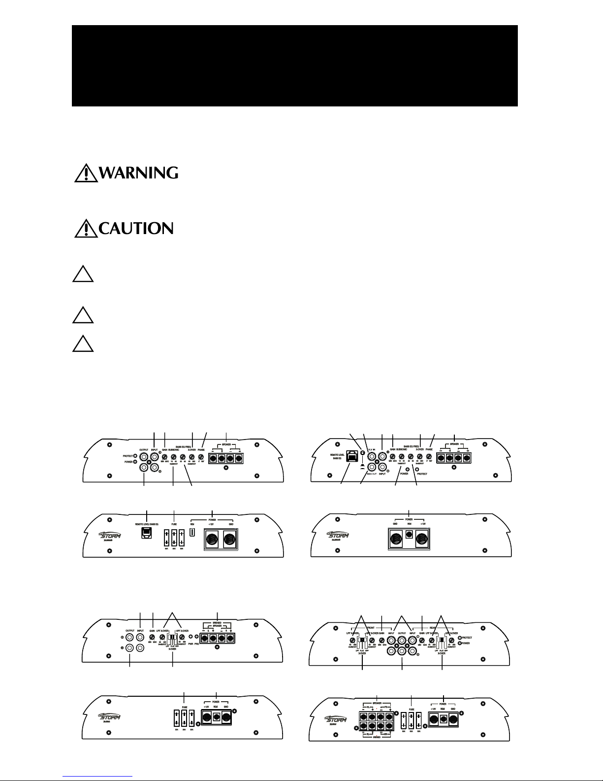
A. RCA Input Jacks – Line Level from Radio Pre-outs: The industry standard RCA jack
provides an easy connection for signal level input. They are platinum to resist the signal
degradation caused by corrosion.
B. Gain Control: The input gain control is preset to match the output of most source units.
They can be adjusted to match output levels from a variety of source units.
C. Adjustable Crossover Frequency Control: 50-250Hz. Low Pass only on Models
X1.1000.1D & X1.2000.1D.
D. Speaker Connections: Follow correct polarity, and do not Ground any speaker wires. Do not
connect any speaker wires together.
E. Crossover Filter Switch: (Models X1.400.2 & X1.800.4 Only)
HPF for High Pass - Mid-Tweeter.
Flat for All Pass - Full Range.
LPF for Low Pass - Subs.
F. Pass Thru Outputs: The Pass-Thru provides a convenient source for daisy-chaining an
additional amplifier without running an extra set of RCA cables from the front of the vehicle
to the rear amplifier location.
G. Power Fuse: If this Fuse should blow, determine the cause or see your authorized dealer.
Never replace the fuse with one of greater value than the original
H. Power Connector terminals: Connects Power, Ground, and Remote
I. Phase: (Models X1.1000.1D & X1.2000.1D Only) Used to vary the inversion of the output,
0°-180°, from input source.
J. SubSonic: (Models X1.1000.1D & X1.2000.1D Only) A high pass filter designed to prevent
frequencies below the audio range from being applied to the subwoofer from the amplifier.
Improving subwoofer performance and power handling.
K. Bass EQ: (Model X1.1000.1D & X1.2000.1D Only) Variable 20-80Hz frequency control. Boost
controlled by remote.
L.
Remote Level/Bass EQ Control: (Models X1.1000.1D & X1.2000.1D Only) Remote level
control attenuates Gain set on the amplifier by up to -20dB. Bass EQ control is 0 to +12dB
Boost of the frequency (20-80Hz) set on the amplifier.
M. Master / Slave Switch: (Model 2000.1D Only) Used to set the amplifier to master or slave
when strapping.
N. SLV IN (slave): (Model X1.2000.1D Only) When strapping, this is the slaved amplifer input
from the master amplifier.
O. MAS OUT (master): (Model X1.2000.1D Only) When strapping, this is the master amplifer
output to the slave amplifier.
INSTALLATION CONSIDERATIONS
The following is a list of tools needed for installation:
Volt/Ohm Meter
Wire strippers
Wire crimpers
Wire cutters
#2 Phillips screwdriver
Battery post wrench
Hand held drill w/assorted bits
1/8" diameter heatshrink tubing
Assorted connectors
Adequate Length—Power Wire
Adequate Length—Remote Turn-on Wire
Adequate Length—Grounding Wire
Page 4

5
Installation
This section focuses on some of the vehicle considerations for installing your new Amplifier. Preplanning your system layout and best wiring routes will save installation time. When deciding on
the layout of your new system, be sure that each component will be easily accessible for making
adjustments.
CAUTION: If you feel unsure about installing this system yourself, have it
installed by a qualified technician.
CAUTION: Before installation, disconnect the battery negative (-) terminal to
prevent damage to the unit, fire and/or possible injury.
Before beginning any installation, follow these simple rules:
1. Be sure to carefully read and understand the instructions before attempting to install the
Unit.
2. For safety, disconnect the negative lead from the battery prior to beginning the installation.
3. For easier assembly, we suggest you run all wires prior to mounting your Unit in place.
4. Route all of the RCA cables close together and away from any high current wires.
5. Use high quality connectors for a reliable installation and to minimize signal or power loss.
6. Think before you drill! Be careful not to cut or drill into gas tanks, fuel lines, brake or
hydraulic lines, vacuum lines or electrical wiring when working on any vehicle.
7. Never run wires underneath the vehicle. Running the wires inside the vehicle provides the
best protection.
8. Avoid running wires over or through sharp edges. Use rubber or plastic grommets to protect
any wires routed through metal, especially the firewall.
9. ALWAYS protect the battery and electrical system from damage with proper fusing. Install
the appropriate fuse holder and fuse on the +12V power wire within 18” (45.7 cm) of the
battery terminal.
10. When grounding to the chassis of the vehicle, scrape all paint from the metal to ensure a
good, clean ground connection. Grounding connections should be as short as possible and
always be connected to metal that is welded to the main body, or chassis, of the vehicle.
MOUNTING LOCATIONS
The mounting position of your amplifier will have a great effect on the sound and performance
produced.
Engine Compartment
Never mount this unit in the engine compartment. Mounting the unit in the engine compartment
will void your warranty.
Passenger Compartment Mounting
Mounting the amplifier in the passenger compartment will work as long as you provide a
sufficient amount of air for the amplifier to cool itself. If you are going to mount the amplifier
under the seat of the vehicle, you must have at least 1" (2.54cm) of air gap around the amplifier's
heatsink.
Mounting the amplifier with less than 1" (2.54cm) of air gap around the amplifier's heatsink in the
passenger compartment will not provide proper cooling and will severely affect the performance
of the amplifier and is strongly not recommended.
BATTERY AND CHARGING
Amplifiers will put an increased load on the vehicle's battery and charging system. We
recommend checking your alternator and battery condition to ensure that the electrical system
has enough capacity to handle the increased load of your stereo system. Stock electrical
systems which are in good condition should be able to handle the extra load of any Lightning
Audio amplifier without problems, although battery and alternator life can be reduced slightly. To
maximize the performance of your amplifier, we suggest the use of a heavy duty battery and an
energy storage capacitor.
!
!
Page 5

6
Installation
WIRING THE SYSTEM
CAUTION: If you do not feel comfortable with wiring your new unit, please see
your local Authorized Lightning Audio Dealer for installation.
CAUTION: Before installation, disconnect the battery negative (-) terminal to
prevent damage to the unit, fire and/or possible injury.
CAUTION: Avoid running power wires near the low level input cables, antenna,
power leads, sensitive equipment or harnesses. The power wires
carry substantial current and could induce noise into the audio
system.
1. Plan the wire routing. Keep RCA cables close together but isolated from the amplifier's
power cables and any high power auto accessories, especially electric motors. This is done
to prevent coupling the noise from radiated electrical fields into the audio signal. When
feeding the wires through the firewall or any metal barrier, protect them with plastic or rubber
grommets to prevent short circuits. Leave the wires long at this point to adjust for a precise
fit at a later time.
2. Prepare the power cable for attachment to the amplifier by stripping 1/2" of insulation from
the end of the wire. Insert the bared wire into the B+ terminal and tighten the set screw to
secure the cable in place.
NOTE: The B+ cable MUST be fused 18" or less from the vehicle's battery. Install the fuseholder
under the hood and prepare the cable ends as stated above. Connections should be water
tight.
3. Trim the power cable within 18" of the battery and strip1/2"of insulation from the end of the
wire.
4. Strip 1/2" from the battery end of the power cable and crimp a large ring terminal to the
cable. Use the ring terminal to connect to the battery positive terminal. DO NOT install the
fuse at this time.
5. Prepare the grounding cable for attachment to the amplifier by stripping 1/2" of insulation
from the end of the wire. Insert the bared wire into the GND terminal and tighten the set
screw to secure the cable in place. Prepare the chassis ground by scraping any paint from
the metal surface and thoroughly clean the area of all dirt and grease. Strip the other end of
the wire and attach a ring connector. Fasten the cable to the chassis using a non-anodized
screw and a star washer.
6. Prepare the REM turn-on wire for connection to the amplifier by stripping 1/2" of insulation
from the wire end. Insert the bared wire into the REM terminal and tighten the set screw to
secure the cable into place. Connect the other end of the REM wire to a switched 12 volt
positive source. The switched voltage is usually taken from the source unit's accessory lead.
If the source unit does not have this output available, the recommended solution is to wire a
mechanical switch in line with a 12 volt source to activate the amplifier.
7. Securely mount the amplifier to the vehicle or amp rack. Be careful not to mount the
amplifier on cardboard or plastic panels. Doing so may enable the screws to pull out from
the panel due to road vibration or sudden vehicle stops.
8. Connect the source signal to the amplifier by plugging the RCA cables/high level inputs into
the input jacks at the amplifier.
9. Connect the speakers. Strip the speaker wires 1/2" and insert into the speaker terminal and
tighten the set screw to secure into place. Be sure to maintain proper speaker polarity. DO
NOT chassis ground any of the speaker leads as unstable operation may result.
10. Perform a final check of the completed system wiring to ensure that all connections are
accurate. Check all power and ground connections for frayed wires and loose connections
which could cause problems.
NOTE: Follow the diagrams for proper signal polarity.
CAUTION: The X1.400.2 and X1.800.4 amplifiers are not recommended for
impedance loads below 2Ω stereo and/or 4Ω bridged (mono).
!
!
!
!
Page 6

7
Installation
X1.1000.1D
X1.2000.1D
X1.400.2
X1.800.4
MONO AMPLIFIERS X1.1000.1D & X1.2000.1D
These amplifiers have two (2) speaker outputs for convenience and are paralleled internally.
CAUTION: The X1.1000.1D and X1.2000.1D amplifiers are not recommended for
impedance loads below 1Ω.
!
Page 7

8
Installation
REMOTE LEVEL/BASS EQ CONTROL
(Models X1.1000.1D & X1.2000.1D Only)
Mounting and installation
1. Find a location, either under the dash or near
the center console, that gives easy access to
the remote.
2. Using the screws supplied, install the mounting
clip with the tabs towards the back.
3. Route the cable for the remote and connect to
both the remote and amplifer.
4. Slip the remote onto the mounting clip until it
snaps into place.
Mounting
Clip
From Source Unit
From Source Unit
From Source Unit
From Source Unit From Source Unit
From Source Unit
X1.400.2
2-Channel
X1.800.4
4-Channel
2-Channel – Bridged
4-Channel –
Set as 3-Channel Bridged
X1.1000.1D
X1.2000.1D
Page 8

USING PASSIVE CROSSOVERS
A passive crossover is a circuit that
uses capacitors and/or coils and is
placed on speaker leads between the
amplifier and speaker. The crossover
delegates a specific range of
frequencies to the speaker for
optimum driver performance. A
crossover network can perform one of
three functions: High-Pass
(capacitors), Low-Pass (inductors or
coils) and Bandpass (combination of
capacitor and coil).
The most commonly used passive
crossover networks are 6dB/octave
systems. These are easy to construct
and require one component per filter.
Placing this filter in series with the
circuit will reduce power to the
speaker by 6dB/octave above or
below the crossover point depending
on whether it is a high-pass or lowpass filter. More complex systems
such as 12dB/octave or 18dB/octave
can cause impedance problems if not
professionally designed.
Passive crossovers are directly
dependent upon the speaker's
impedance and component value for
accuracy. When passive crossover
components are used in multiple
speaker systems, the crossover's
effect on the overall impedance should
be taken into consideration along with
the speaker's impedance when
determining amplifier loads.
CAUTION: The Lightning Audio amplifiers are not recommended for impedance
loads below 2Ω stereo and 4Ω bridged (mono) loads.
9
Installation
80 4.1mH 1000mF 8.2mH 500mF 16mH 250mF
100 3.1mH 800mF 6.2mH 400mF 12mH 200mF
130 2.4mH 600mF 4.7mH 300mF 10mH 150mF
200 1.6mH 400mF 3.3mH 200mF 6.8mH 100mF
260 1.2mH 300mF 2.4mH 150mF 4.7mH 75mF
400 .8mH 200mF 1.6mH 100mF 3.3mH 50mF
600 .5mH 136mF 1.0mH 68mF 2.0mH 33mF
800 .41mH 100mF .82mH 50mF 1.6mH 26mF
1000 .31mH 78mF .62mH 39mF 1.2mH 20mF
1200 .25mH 66mF .51mH 33mF 1.0mH 16mF
1800 .16mH 44mF .33mH 22mF .68mH 10mF
4000 .08mH 20mF .16mH 10mF .33mH 5mF
6000 51mH 14mF .10mH 6.8mF .20mH 3.3mF
9000 34mH 9.5mF 68mH 4.7mF .15mH 2.2mF
12000 25mH 6.6mF 51mH 3.3mF 100mH 1.6mF
Freq.
Hertz
Speaker Impedance
2 OHMS
8 OHMS
4 OHMS
L L
L
C C
C
6dB/Octave Low-Pass
6dB/Octave High-Pass
L
C
L = Low-Pass (Inductor)
C = High-Pass (Capacitor)
For more information, see your Authorized Lightning
Audio Dealer.
!
Page 9

10
Operation
ADJUSTING GAIN
To adjust the gain setting, turn the amplifier gains all the way down. Turn the source unit volume
up until distortion is audible and then turn it down a bit until the distortion is inaudible. This will
be about two thirds all the way up on most source units. Next, turn the amplifier gain setting
until once again distortion is audible and then back it down until the distortion is inaudible.
NOTE: For a more in depth setting procedure, contact Lightning Audio Technical Support.
ADJUSTING CROSSOVER (X-OVER)
Models X1.400.2 & X1.800.4
Placing the switch in the HPF position sets the amplifier to the High Pass mode, enabling
frequencies above the cut-off point to pass, adjustable between 50-250Hz.
Placing the switch in the FLAT position sets the amplifier to the All Pass mode, preventing any
crossover adjustment, allowing all frequencies to pass..
Placing the switch in the LPF position sets the amplifier to the Low Pass mode, enabling
frequencies below the cut-off point to pass, adjustable between 50-250Hz.
Turn the crossover adjustment knob all the way down. With the system playing, turn the
crossover adjustment knob up slowly until the desired crossover point is achieved.
Models X1.1000.1D & X1.2000.1D
Turn the crossover adjustment knob all the way down. With the system playing at normal
listening level, turn the crossover adjustment knob up slowly until the desired crossover point is
achieved.
SUBSONIC (Models X1.1000.1D & X1.2000.1D Only)
A high pass filter designed to prevent frequencies below the audio range from being applied to
the subwoofer from the amplifier.
Set this to your personal preference while listening to the system.
PHASE (Models X1.1000.1D & X1.2000.1D Only)
This varies the inversion of the output signal from 0° to 180° from the input signal. Set this to
your personal preference while listening to the system.
BASS EQ (Models X1.1000.1D & X1.2000.1D Only)
Used with the Remote Level/Bass EQ Control, the control will boost the frequency of what is set
here.
Example: If the Bass EQ Freq on the amplifier is set to 50Hz, the Remote will boost that frequency.
Gain Bass EQ Crossover
Phase
Subsonic
Gain
Crossover
X1.1000.1D
X1.2000.1D
is Simular
X1.400.2
X1.800.4
is Simular
Page 10

11
Operation
STRAPPING AMPLIFIERS (X1.2000.1D Only)
The X1.2000.1D amplifiers have the ability to connect two together and have their outputs
combined, or strapped, to power a single speaker load.
CAUTION: Two X1.2000.1D amplifiers that are strapped together are not
recommended for impedance loads below 2Ω.
1. Select which amplifier of the two will be the master. and set the Master/Slave switch in the
"out" position.
NOTE: Only adjustments made to the master amplifier will effect the output to the connected
speaker.
2. Connect RCA cables from the source signal to the input connection on the master amplifier.
3. Set the Master / Slave switch on the slave amplifier to the "in" position.
4. Connect a RCA cable from the MAS OUT connector on the master amplifier to the SLV IN
connector on the slave amplifier.
5. Connect one of the negative (-) speaker outputs from the master amplifier to one of the
negative (-) speaker outputs on the slave amplifier using a 10 gauge wire (minimum).
6. Connect one of the positive (+) speaker outputs from the master amplifier to the positive (+)
terminal of the speaker being use.
7. Connect one of the positive (+) speaker outputs from the slave amplifier to the negative (-)
terminal of the speaker being use.
!
Page 11

12
Specifications
Specifications subject to change without notice
Troubleshooting
Symptom Diagnosis Remedy
Amplifier does not
turn on.
Amplifier Noise
(Turn-On Pop)
Engine Noise
B+ or REM not between 10.5 and
15.5 volts or no voltage present
Amplifier is not properly grounded.
Voltage spike from source unit is
entering amplifier’s input
Noise is radiating into signal cables
Check the alternator, battery, fuse,
and wiring and repair as necessary
Check wiring and repair as necessary
Connect a relay turn-on module to
REM terminal if pops are eliminated
with no input signal to amplifier
Re-route signal cables away from
sources of high current
MODEL- Storm X1.1000.1D X1.2000.1D X1.400.2 X1.800.4
Continuous Power Rating (RMS) - Measured at 14.4 Battery Volts
4Ω Load Per Channel 400 Watts x 1 700 Watts x 1 100 Watts x 2 100 Watts x 4
2Ω Load Per Channel 700 Watts x 1 1200 Watts x 1 200 Watts x 2 200 Watts x 4
4Ω Load Bridged (Mono) 400 Watts x 1 400 Watts x 2
X1.1000.1D & X1.2000.1D Only
1Ω Load Bridged 1000 Watts x 1 2000 Watts x 1
Dimensions: add 1.5" (xcm) to length for mounting feet
Height 2.2" (5.6cm) 2.2" (5.6cm) 2.2" (5.6cm) 2.2" (5.6cm)
Width 10.4" (26.42cm) 10.4" (26.42cm) 10.4" (26.42cm) 10.4" (26.42cm)
Length 14" (35.56cm) 22.0" (56.00cm) 15.2" (30.61cm) 18.6" (47.24cm)
Signal-to-Noise Ratio >90dB A-weighted
Input Sensitivity 150mV - 4V
Crossover (X1.1000.1D & X1.2000.1D only) 24dB/octave Low Pass only
Crossover (X1.400.2 & X1.800.4 only) 24dB/octave HPF/Flat/LPF Switch
Crossover Frequency variable from 50Hz to 250Hz
Channel Separation 50dB
Bass Equalization (X1.1000.1D & X1.2000.1D only) Variable from 0dB to +12dB @ 20-80Hz
 Loading...