


 Loading...
PRONET
Loudspeaker Control Software
USER MANUAL
RELEASE 2.1
1

Summary
1 |
Introduction ................................................................................................................................. |
4 |
||
|
1.1 |
Welcome to PRONET: the PRONET philosophy ..................................................................... |
4 |
|
|
1.1.1 |
What's New? .................................................................................................................. |
4 |
|
|
1.2 |
Contacts................................................................................................................................. |
4 |
|
|
1.3 |
Credits.................................................................................................................................... |
4 |
|
2 |
Installation.................................................................................................................................... |
5 |
||
|
2.1 |
Requirements ........................................................................................................................ |
5 |
|
|
2.2 |
Software installation.............................................................................................................. |
5 |
|
|
2.3 |
Drivers.................................................................................................................................... |
5 |
|
|
2.3.1 Drivers installation for Windows 7 / 8 (32/64 bit) ......................................................... |
5 |
||
|
2.3.2 Drivers installation for Windows XP............................................................................... |
8 |
||
|
2.4 |
Uninstall................................................................................................................................. |
9 |
|
|
2.5 |
Updates ................................................................................................................................. |
9 |
|
|
2.6 |
Release notes......................................................................................................................... |
9 |
|
|
2.6.1 PRONET Suite END USER License Agreement ................................................................ |
9 |
||
|
2.6.2 |
Technical support ........................................................................................................... |
9 |
|
3 |
Working with PRONET................................................................................................................ |
10 |
||
|
3.1 |
Application windows ........................................................................................................... |
10 |
|
|
3.2 |
Device Tree window ............................................................................................................ |
10 |
|
|
3.3 |
Desktop window and control panels................................................................................... |
12 |
|
|
3.4 |
Edit panels ........................................................................................................................... |
13 |
|
|
3.5 |
Menu ................................................................................................................................... |
13 |
|
|
3.6 |
Toolbar................................................................................................................................. |
15 |
|
|
3.7 |
Status bar............................................................................................................................. |
15 |
|
|
3.8 |
Settings ................................................................................................................................ |
16 |
|
|
3.9 |
Save/ Recall Desktop configurations ................................................................................... |
17 |
|
4 Connecting devices to a network............................................................................................... |
18 |
|||
|
4.1 |
Configuring devices for the network................................................................................... |
18 |
|
|
4.2 |
Assigning ID ......................................................................................................................... |
19 |
|
|
4.3 |
USB2CAN converter............................................................................................................. |
20 |
|
|
4.4 |
USB connection ................................................................................................................... |
20 |
|
|
4.5 |
Working online/offline ........................................................................................................ |
20 |
|
|
4.5.1 |
Going online ................................................................................................................. |
20 |
|
|
4.5.2 Going offline and using virtual devices ........................................................................ |
22 |
||
5 |
Working with devices................................................................................................................. |
23 |
||
|
5.1 |
Control panels ..................................................................................................................... |
23 |
|
|
5.1.1 |
Processor panel............................................................................................................ |
23 |
|
|
5.1.2 |
Active loudspeaker panel............................................................................................. |
24 |
|
|
5.1.3 |
Active subwoofer panel ............................................................................................... |
24 |
|
|
5.2 |
Setup panels ........................................................................................................................ |
25 |
|
|
5.2.1 |
Processor setup panel.................................................................................................. |
25 |
|
|
5.2.2 Active loudspeaker setup panel................................................................................... |
27 |
||
6 |
Editing PC240/260 parameters .................................................................................................. |
28 |
||
|
6.1 |
Input page............................................................................................................................ |
28 |
|
|
6.1.1 |
Input Level.................................................................................................................... |
29 |
|
|
6.1.2 |
Input Delay ................................................................................................................... |
29 |
|
2

|
6.1.3 |
Compressor .................................................................................................................. |
30 |
|
|
6.2 |
Output page......................................................................................................................... |
32 |
|
|
6.2.1 |
Output Level................................................................................................................. |
33 |
|
|
6.2.2 |
Output Compressor/Limiter......................................................................................... |
34 |
|
|
6.2.3 |
Output Delay ................................................................................................................ |
35 |
|
|
6.3 |
GEQ page ............................................................................................................................. |
35 |
|
|
6.4 |
PEQ page.............................................................................................................................. |
37 |
|
|
6.5 |
DEQ page ............................................................................................................................. |
40 |
|
|
6.5.1 How Dynamic Equalization works ................................................................................ |
40 |
||
|
6.5.2 |
Parameters ................................................................................................................... |
41 |
|
|
6.6 |
Output page......................................................................................................................... |
43 |
|
|
6.6.1 |
Crossover section ......................................................................................................... |
44 |
|
|
6.6.2 |
PEQ section .................................................................................................................. |
45 |
|
|
6.6.3 |
Level section................................................................................................................. |
45 |
|
|
6.7 |
Global page.......................................................................................................................... |
46 |
|
|
6.8 |
RTA page .............................................................................................................................. |
47 |
|
|
6.9 |
SPLM page ........................................................................................................................... |
48 |
|
|
6.10 |
|
Setup page ....................................................................................................................... |
51 |
|
6.11 |
|
Preset control................................................................................................................... |
52 |
7 |
Editing Loudspeaker parameters ............................................................................................... |
54 |
||
|
7.1 |
In/Out page ......................................................................................................................... |
54 |
|
|
7.1.1 |
Input Level.................................................................................................................... |
55 |
|
|
7.1.2 |
Input Delay ................................................................................................................... |
56 |
|
|
7.1.3 |
Compressor - limiter .................................................................................................... |
57 |
|
|
7.1.4 |
Output Level Trim......................................................................................................... |
58 |
|
|
7.1.5 HPF / LPF filter.............................................................................................................. |
58 |
||
|
7.2 |
PEQ page.............................................................................................................................. |
59 |
|
|
7.3 |
DEQ page ............................................................................................................................. |
62 |
|
|
7.3.1 |
Parameters ................................................................................................................... |
63 |
|
|
7.4 |
Global page.......................................................................................................................... |
64 |
|
|
7.5 |
Setup page........................................................................................................................... |
65 |
|
|
7.6 |
Preset control ...................................................................................................................... |
66 |
|
8 |
Printing....................................................................................................................................... |
68 |
||
9 Working with advanced functions ............................................................................................. |
69 |
|||
|
9.1 |
Working with files................................................................................................................ |
69 |
|
|
9.1.1 Load Data from file....................................................................................................... |
69 |
||
|
9.1.2 Save Data to file ........................................................................................................... |
69 |
||
|
9.2 |
Groups and links .................................................................................................................. |
70 |
|
|
9.2.1 Create and manage a group......................................................................................... |
70 |
||
|
9.2.2 |
Group controllers ......................................................................................................... |
71 |
|
|
9.3 |
Security options................................................................................................................... |
72 |
|
|
9.3.1 |
Using Lock Modes ........................................................................................................ |
73 |
|
|
9.4 |
Firmware Update................................................................................................................. |
74 |
|
|
9.4.1 |
Processor Update Utility .............................................................................................. |
75 |
|
|
9.4.2 CORE PROCESSED speakers Update Utility .................................................................. |
75 |
||
3

1 Introduction
1.1 Welcome to PRONET: the PRONET philosophy
PRONET has been designed by PROEL Research & Development Department to control a network of multiple devices like active loudspeakers and speaker management processors.
With PRONET you can control each connected device, visualize signal levels, monitor internal status and edit the parameters of the powerful CORE digital signal processing.
PROEL Research and Development department has designed this application in collaboration with sound engineers and sound designers, in order to give you an "easy-to-use" tool to manage your audio system. We are proud to present you a simple and intuitive interface, a reliable connection protocol and a minimal initial setup ready to manage every live performing, venue or situation.
1.1.1 What's New?
Release 2.1:
-New AXIOM loudspeaker models added.
-Enhanced management of the Control Panels.
-Minor bugs fixed.
Note: The older PC260/PC240 firmware releases 1.0 or 1.1 are not compatible with the Pronet rel.2.0 software or other newer releases. In order to use the new features of Pronet software you must upgrade the firmware of your PC260/PC240 devices: see “Firmware Update” for a more detailed description of the update process.
1.2 Contacts
The PRONET home page is at http://www.proel.com. For a help with PRONET or to report bugs, please mail to info@proel.com
Proel S.p.A.
Via alla Ruenia 37/43
CAP 64027 Sant'Omero (TE) ITALY Tel. +39 0861 81241 info@proel.com
1.3 Credits
Designed and Programmed by: Research and Development Department of Proel. Copyright (c) 2011 by Proel S.p.A.
Thank you also to:
-Our beta testers;
-Sound engineers and sound designers who collaborate with us;
-VSCP team;
4

2 Installation
Download PRONET software by visiting www.proel.com
2.1 Requirements
Before installing your copy of PRONET, you must verify that your computer meets some minimum requirements to work. These requirements are:
-Intel Pentium IV (1.8 GHz or higher)
-1 GB RAM memory
-Screen resolution 1024 X 768 (minimum)
-25 MB Free Hard disk space
-USB port (2.0 recommended, also 1.1 supported)
-Windows™ O.S - XP (service pack2) / VISTA / 7 / 8
If your computer meets or exceeds these requirements, the software will be installed and operate without any problem.
Before starting the installation, be sure to not connect any device to the PC until the end of the installation process. It is also recommended to close all applications currently in use.
Follow the instructions to install the right drivers at the end of the installation process as explained in the section “Drivers”.
Note that you must be logged on as an administrator to perform the PRONET software installation steps and to install the required drivers. Please, verify yours authorizations before to proceed with the installation!
2.2 Software installation
Run the installation program double-clicking on it. This will create a program folder called PRONET (or the name you have chosen). This folder can be accessed via the Start menu under Programs. The folder contains shortcut to the program, shortcut to the manual and uninstall.
Note: If you have a software firewall running on your PC, the first time you open PRONET application, or the first time you goes online and scan the PRONET Network (see “Connecting devices to a network” and Working online/offline”), probably you will receive a System/Firewall warning regarding an application called “vscpd.exe”. It is not a virus or a malware, but just a small background application that manages the PRONET network communication through the USB port. Allow this program to access the network and, if you can, set the option "Remember my answer and don't ask me again.
2.3 Drivers
The first time you connect a PROEL USB to CAN converter (USB2CAN) or the first time you connect a PC240/PC260 processor via the USB connection, a “USB2CAN” driver will be requested. Here below we describe the procedure for installing this driver.
2.3.1 Drivers installation for Windows 7 / 8 (32/64 bit)
You can find the driver files in the default PRONET installation folder:
C:\Program Files\Proel\PRONET\Driver\x86-32bit or C:\Program Files\Proel\PRONET\Driver\x86-64bit
If you have changed the installation folder, you need to specify the new directory path, e.g.
<your installation path>\ PRONET\Driver\x86-32bitor<your installation path>\ PRONET\Driver\x86-64bit
Here below you can find a visual step-by-step guide to install the USB2CAN driver.
5

Step 1: Connect the USB2CAN converter or the PC240/260 USB connector to the USB port of your PC: Windows O.S. will detect the new hardware connected and will ask for the drivers.
First of all Windows 7 / 8 will try to download the driver from Window Update repository, skip this download and proceed with the manual installation of drivers.
Step 2: Open the Control Panel from Start menu and then click to open Device Manager. If you are prompted for an administrator password or confirmation, type the password or provide confirmation.
Open the list of hardware categories, find the “other devices”/USB2CAN driver that you want to install/update, and then right-click the name.
Click “Update Driver”, and then follow the instructions. If you are prompted for an administrator password or confirmation, type the password or provide confirmation.
Step 3: Select the path of the folder driver in the PRONET installation folder.
C:\Program Files\Proel\PRONET\Driver\x86-32bit or C:\Program Files\Proel\PRONET\Driver\x86-64bit
Ignore the Windows warning about the driver publisher.
Step 4: Windows will tell you if the drivers are successfully installed in Windows Device Manager Panel.
Fig.1 Windows 7/8 driver installation: skip obtaining drivers from Windows Update (STEP 1)
Fig.2 Windows 7/8 driver installation: confirm to skip getting drivers from Windows Update (STEP 1)
Fig.3 Windows 7/8 driver installation: just close this panel (STEP 1)
Fig.4 Windows 7/8 driver installation: update USB2CAN driver in “Control Panel - Device Manager” (STEP 2)
6
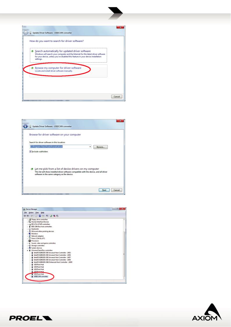
Fig.5 Windows 7/8 driver installation: browsing for driver software (STEP 3)
Fig.6 Windows 7/8 driver installation: selecting the driver’s path(STEP 3)
Fig.7 Windows 7/8 driver installation: check the right installation for the USB2CAN controller's driver (STEP 4)
7

2.3.2 Drivers installation for Windows XP
Step 1: Connect the USB2CAN converter to the USB port of your PC, Windows O.S. will detect the new hardware connected and will ask for the drivers.
Step 2: Select the path of the folder driver in the PRONET installation folder.
When required, skip the Windows Logo warning message and continue the installation of USB2CAN driver.
At the end of the installation Windows will tell you if the drivers are successfully installed in Windows Device Manager Panel.
Step 3: You can verify the right driver installation for the USB2CAN converter in the Device Manager Panel (Fig.11).
Fig.10 Driver path (STEP 2)
Fig.8 Found new hardware (STEP 1)
Fig.9Driver installation (STEP 2)
Fig.11 Verify USB2CAN driver installation (STEP 3)
8

2.4 Uninstall
You can uninstall PRONET either by double-clicking the Uninstall PRONET icon in the PRONET folder group, or by invoking the Windows Control Panel, double-clicking on Add/Remove Programs, and then choosing the PRONET item.
2.5 Updates
Check for updates visiting www.proel.com at the Download section.
2.6Release notes
2.6.1PRONET Suite END USER License Agreement
This PRONET software ("Software") is owned by Proel S.p.A. Proel S.p.A. hereby grants to the user a nonexclusive license to use this Software solely with his products. User shall not commercially distribute, sublicense, resell, or otherwise transfer for any consideration, or reproduce for any such purposes, the Software or any modification or derivation thereof, either alone or in conjunction with any other products or programs. Further, the user shall not disassemble, reverse engineer, modify, decompile, or otherwise abuse the intended purpose under this License Agreement.
This Software is provided to the user "AS IS." Proel S.p.A. assumes no risk if this Software does not function properly or doesn’t operate error free and Proel S.p.A. makes no warranties, either expressed or implied, with respect to the Software and/or associated materials provided to the user, including but not limited to any warranty of merchantability or fitness for a particular purpose. Further, Proel S.p.A. shall not be liable for any claims or damages whatsoever, including property damage, personal injury, intellectual property infringement, loss of profits, or interruption of business, or for any special, consequential or incidental damages, however caused, whether arising out of breach of warranty, contract, tort (including negligence), strict liability, or otherwise.
Proel S.p.A. reserves the right at any time to release a commercial release of the Software or, if released, to change prices, specifications, features, licensing terms, release dates, general availability or other characteristics of the commercial release without further notification to the user.
REPRODUCTION OF THIS SOFTWARE AND ITS MEDIA IS STRICTLY PROHIBITED.
2.6.2 Technical support
Software technical support is provided at the PRONET web site (www.proel.com). Email support is provided as a courtesy and at the discretion of Proel S.p.A.
9

3 Working with PRONET
In this section of the manual you will find a brief description of PRONET application, its main windows, resources and tools to start working. For a detailed description of each feature see the following chapters.
3.1 Application windows
Let’s take a little tour of the PRONET graphic interface to learn how to use it and how to use the graphic tools.
Fig.12 Description of PRONET graphic windows.
3.2 Device Tree window
Device tree window display a tree list of devices actually connected to PRONET. Every device is listed as a leaf of the root and is labeled with its main info:
-device's ID, a unique identifier number for each device (see “Connecting devices to a network” or “Working online/offline”);
-device type and model;
-device name;
If PRONET works online the root of tree is labeled “NETWORK”: in this case the device tree shows every recognized device connected in the network and its connection status. If the device is correctly connected it has a green background label, if it is disconnected it has a red background label and a graphic check sign on its icon.
Fig.13 Connected device.
10
Fig.14 Disconnected device
If PRONET works offline, the root of tree is labeled “VIRTUAL” and the device tree window shows virtual devices you have added to your virtual network. Virtual devices have gray-background labels.
Fig.15 Virtual devices added working offline.
The device tree also shows the presence of “Group Controllers” (see “Groups and links”). They can be added either online or offline.
When changing PRONET status from Offline to Online the device tree list is cleared and recompiled, searching every connected device. When changing PRONET status from Online to Offline the device tree list is cleared. Group controllers, on the contrary, aren’t automatically removed from the tree; they have to be removed from the menu option.
Fig.16 Example of devices, controllers and group folders for a virtual network.
Fig.17 Example of devices, controllers and group folders for a network of devices.
11
Devices in the tree list are sorted by their ID or grouped in folders if they are assigned to any group.
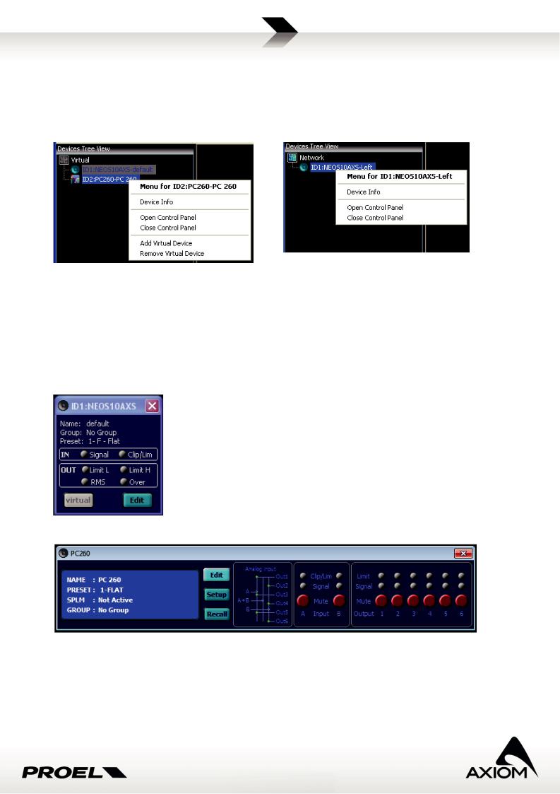
A Right-Click of mouse in a device leaf of the tree list opens a contextual menu with some actions available for the selected device: you can open and close the control panel, or, if you are working offline, you can add or remove a virtual node.
Fig.19 Contextual menu for devices (working online).
Fig.18 Contextual menu for virtual devices (working offline).
3.3 Desktop window and control panels
The Desktop window contains the control panel of devices managed by PRONET. Just double-click on the tree list device label (for a virtual device or a connected device) to open the control panel or use the menu option Menu→Device→Open Control Panel.
The control panels are compact windows that display main features, configurations and status (protections, signal/clipping, preset currently used, etc...) of devices in the tree list.
Fig.20 Example of an active loudspeaker control panel.
Fig.21 Examples of a loudspeaker processor control panel.
See “Working with devices” and “Control panels” for a more detailed description of control panels.
12
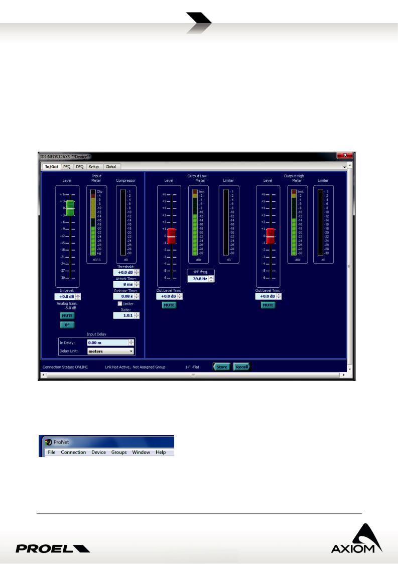
3.4 Edit panels
The Edit panels give you the access to the CORE processing blocks.
There are different types of edit panels for active full-range loudspeakers, active subwoofers and processors, but they are based on the same processing algorithms.
To open an edit panel just click on the “Edit” button in the control panel of the selected device or use the menu option Menu→Device→Edit Device.
For a complete description of the pages in the Edit panels and for a complete description of the parameters of DSP processing blocks see “Editing Processor parameters” and “Editing Loudspeaker parameters”.
Fig.22 Example of an edit panel.
3.5 Menu
Fig.23 PRONET Menu.
The menu-bar allows you to manage many functions such as setting devices, going online or offline, loading and saving files, use the help and so on. There are some keyboard shortcuts that are displayed next to the menu item labels, which can help you to save time!
13

File menu
Load Data from file (Ctrl+L): loads saved data from a file in the hard disk of the computer (or any removable support) to the current setup of the selected device.
Save Data to file (Ctrl+S): saves the current data of a device into a file in the hard disk of the computer or in any other removable support.
Load Desktop: loads a saved desktop file to current desktop window.
Save Desktop: saves current desktop graphic setup to a file in your hard disk (or any removable support).
Settings (Ctrl+G): opens the Settings panel for modifying PRONET options.
Print (Ctrl+P): prints current data for selected devices.
Preview: previews the printing data for selected devices.
Print setup: sets printer options.
Exit (Alt+F4): Quits the application.
Connection menu
Online (Ctrl+O): goes Online. Offline (Ctrl+N): goes Offline.
Rescan (Ctrl+R): rescans the network and re-creates the device tree (available only if PRONET is Online).
Device menu
Add virtual device: adds a virtual device to the device tree (available only if PRONET is Offline).
Remove virtual device: removes the selected virtual device from the device tree (available only if PRONET is Offline).
Clear all virtual devices: removes all virtual devices from the device tree (available only if PRONET is Offline).
Open control panel: opens the control panel of the selected device in the device tree. Close control panel: closes the control panel of the selected device in the device tree.
Manage device control panels (Ctrl+C): opens a special panel to manage (open or close) control panel of multiple devices.
Device info: gets main information about the selected device.
Edit device properties (Ctrl+E): opens the edit interface for the selected device (see “”). The device control panel has to be already open in the desktop window.
14

Modify device setup (Ctrl+M): opens the setup interface for the selected device (see “Setup panels”). The device control panel has to be already open in the desktop window.
Groups menu
Refer to “Working with advanced functions” and “Groups and links” for more information. Group settings: opens a manager interface for groups.
Open group: opens the control panel for each device assigned to the same group of the selected device (‘Not assigned group’ is taken as a group assignment for this action).
Close group: closes the control panel (if open) for each device assigned to the same group of the selected device (‘Not assigned’ group is taken as a group assignment for this action).
Enable link (Ctrl+K): opens the settings page for the link option. Add group control: adds a group controller.
Remove group control: removes the selected group controller.
Window menu
Manages the position and the selection of control panels in the desktop window.
Help menu
Open the “About...” info panel or the PRONET’s help file.
3.6 Toolbar
Fig.24 PRONET Toolbar.
Toolbar provides you shortcuts to some useful operations.
3.7 Status bar
Fig.25 PRONET Status Bar.
Status bar displays some useful information:
-Connection status (online/offline)
-Edit mode (available in future releases or for factory’s advanced settings)
-Lock level of the system (Not Enabled / Lock level if enabled)
-Group Link status (Active / Not active)
15
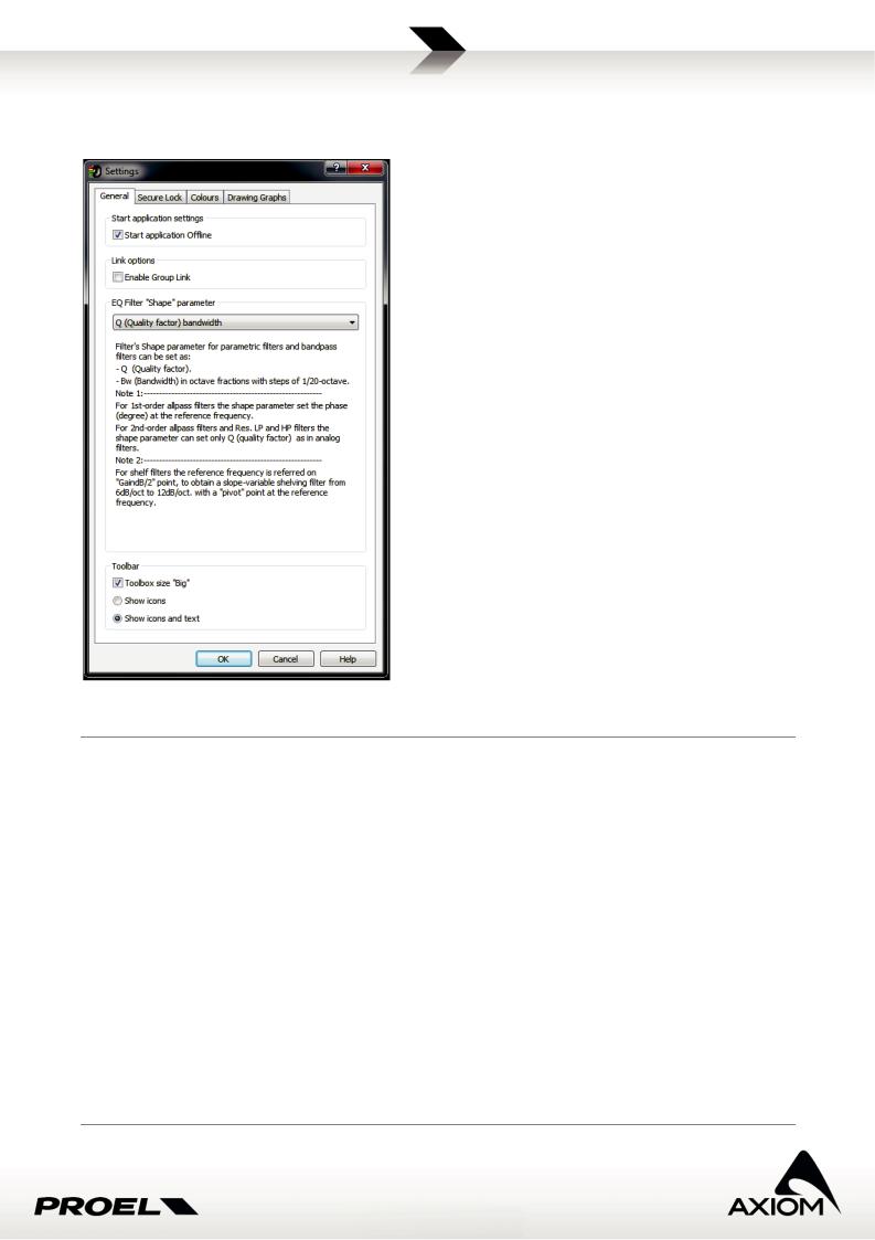
3.8 Settings
In “Settings” panel you can set some options for PRONET usage.
Fig.26 Settings panel for PRONET's properties.
General
Start application settings: sets if the application starts online or offline. If it starts offline you can go online whenever you want using the toolbar button “Online” or selecting the menu item
Menu→Connection→Online.
Link options: enables or disables the “Link” option (see “Groups and links”).
EQ filter “Shape” parameter: sets the parameter “width of the bell” for parametric equalizer filters. The parameter can be Q, defined as the ratio of the center frequency (reference frequency) of the filter and the bandwidth measured at the -3 dB points, or it can be Bw (Bandwidth) in octave fractions with steps of 1/20octave (at -3dB points).
For 1st-order All Pass filters the shape parameter sets the phase (degree) at the reference frequency. For 2nd-order All Pass filters and “Variable Q” LP and HP filters the shape parameter can set only Q (quality factor) as in analog filters.
For shelf filters the reference frequency is referred to "Gain dB/2" point, in order to obtain a slope-variable shelving filter from 6dB/oct to 12dB/oct with a "pivot" point at the reference frequency.
Toolbar: Set the aspect of the application toolbar.
16

Secure lock
Enable lock mode: Enable the advanced function to lock some parameters of the application and the connected devices (See “Security options”).
User lock level: Set the lock level for the application and the connected devices (See “Security options”).
Colors
Color settings: Customize colors for Desktop window, Device tree window, and Edit panel. Desktop background: you can choose a bitmap image as background of PRONET desktop window.
Drawing graphs
Axes scale: sets the scale of graph visualization in eq. pages of PRONET and the visualization of the phase plot. This is a global setting. In each editing page you can change temporarily these parameters.
Global graph settings (available only in Advanced Mode): selects what you can plot in the Global Graph page for the Editing panel of devices. Note that for loudspeaker devices in Global Graph page you can visualize the amount of equalization from input to output of processing core. For processors devices (e.g. PC240, PC260) in Global Graph page you can visualize only the output equalization curve, not the input equalization.
Colors: sets the colors for graphic visualization of equalization curves.
Eq. drag options: sets which parameters can be dragged and edited with mouse in the graphic editing of equalization curves.
3.9 Save/ Recall Desktop configurations
To easily manage your systems you can save and then recall some basic graphic settings of your desktop configuration.
In Menu→File→Save Desktop or Menu→File→Load Desktop you can save and recall your favorite color settings, the desktop image setting and most of all, the position of opened control panels in the desktop.
Note that the position of each control panel on the desktop is associated to the ID of the controlled device, so it becomes really useful when you recall a desktop setup for a system already configured.
If you change the ID assignment for a device in a configured system, then the stored ID and panel-position information don’t match with the new ID. If you recall a desktop configuration the control panel can’t be placed in the right position.
17

4 Connecting devices to a network
The main purpose of PRONET is to setup and to monitor a system of many active loudspeakers, to configure easily a single loudspeaker processor or manage a complex system with more processors and loudspeakers.
In order to do that, our engineers have developed a networking system based on a robust, reliable and fast communication protocol to interconnect every device with simple RJ45 cat.5 (or higher) Ethernet cables. With a simple operation you can configure the devices to work in a PRONET network, and just only a Proel’s USB2CAN converter is required.
To configure a single processor (i.e. a PC260 with both USB and PRONET network connections or a PC240 who doesn’t have a PRONET networking connection), there is the possibility to use a direct connection from the PC to the device by the USB ports.
4.1 Configuring devices for the network
PRONET network is an interconnection of devices, the network can be connected and controlled with a PC, called "master controller", who can fully control every connected device called "slave device".
PRONET network can also be connected without a PC but only with a sub-system of active loudspeakers.
Devices in the PRONET network are connected with a "bus-topology" by cat.5 (or cat.6) Ethernet cables. The first device (the PC master controller with its USB2CAN converter) is connected to the network input connector of the second device, the second device network output is connected to the network input connector of the third device, and so on. IMPORTANT: the last device connected at the network bus must be "TERMINATED" by pressing the "TERMINATE" switch near the network connectors in the rear panel of the device.
Pronet network connection
USB2CAN |
USB connection |
converter |
|
TERMINATE
Fig.27 Schematic diagram for a PRONET network .
18

To work properly in a PRONET network each connected device must have a unique Identifier Number called
ID: by default the PC master controller has ID=0 and there can be only one master controller in a network. Any other device connected must have its own unique ID equal or greater than 1 and two devices with the same ID cannot exist in a network.
To correctly assign a new available ID to all devices in a PRONET network follow these steps:
1.power-off all devices;
2.plug them correctly with networking cables;
3."TERMINATE" last device in the network connection;
4.go to the first device in the network connection;
5.power-on the device while pushing the "Assign ID" button (see "Assign ID");
6.go to the next device in the network and repeat previous operation (from steps 5);
This operation ensures that every device has its own unique ID: if you need to add a new device to the network you simply repeat the operation at the step 5.
Every device maintains its ID also when it is turned-off, because the identifier is stored in the internal memory and it is cleared only by another "Assign ID" step, as explained below.
Note 1:if you add a new device as the last device in a PRONET network you have to re-assign correctly the termination.
Note 2: In a PRONET network the IDs don't need to be sequential, they only must be unique. An example of this is when you remove or power-off a device correctly assigned and already working into a network: in this case there is a gap in the IDs sequence but this isn't a problem. Another example is when you add to an existing PRONET network a new device with the ID already assigned but different from any other already assigned in the network: again, this is not a problem.
You can also work without a PC master controller and connect a subsystem of active loudspeakers (satellites or subwoofers): in this kind of network, when you change a preset in a device you also change the same preset in each connected device of the same type (the same model). Furthermore, when you change the polarity (phase option) in a subwoofer you also change the same parameter in all the connected subwoofers (of the same type).
4.2 Assigning ID
The "Assign ID" procedure for a device makes the internal network controller to perform two operations:
1.reset the current ID;
2.search the first free ID in the network, starting from ID=1.
If no other devices are connected (and powered on, of course), the controller assume ID=1, that is the first free ID, otherwise it searches the next one left free.
To activate the "Assign ID" procedure there is a combination of "Power-ON" and keep pressed a button: Processor: power-on keeping pressed the "RTA" button;
Active loudspeaker: power-on keeping pressed the "Preset" button;
19
4.3 USB2CAN converter
To work with a PRONET network you need a USB2CAN converter. To install the correct software driver for the USB2CAN converter see "Installation" and "Drivers" paragraphs.
When you plug in the converter to a USB port of the PC, the LED on box lights in RED, meaning that the converter is powered but not working yet.
The first time you go "online", the PRONET software application starts checking the network through the USB2CAN controller, sending and receiving data from connected devices. If everything is OK, the LED on the top of the converter lights in GREEN indicating the activities on the network.
If there is a problem with the software driver, with network bus or in the converter, the LED flashes in RED and/or GREEN.
RED/GREEN toggling |
PC USB driver isn't installed |
|
RED steady |
converter is not working |
|
GREEN steady |
converter is working |
|
GREEN blinking slow |
There is a problem in the bus |
|
GREEN blinking fast |
There is a problem in the bus |
|
RED blinking slow |
There is a problem in the bus |
|
RED and GREEN steady |
Service upgrade mode |
Fig.28 Led color codes for the USB2CAN converter.
4.4 USB connection
For controlling PC240/PC260 devices a direct USB connection is also available. This connection is always available and enabled for PC240 processor, which doesn't have a network connection. For PC260, which has both USB and a PRONET network connections, the USB connection is active by default and the network connection can be enabled in the ‘SETUP’ menu.
Before connecting a processors with USB cable, please refer to "Installation" and "Drivers" paragraphs because PRONET uses the same software driver both for the USB2CAN converter and the USB connection.
4.5 Working online/offline
PRONET application works in two different modes: online and offline. When online PRONET searches any connected device, reads all the internal data and continuously checks its status. When offline PRONET works with “virtual” devices in a “virtual network”.
You can switch from online to offline mode or vice versa in any moment just selecting the option in
Menu→Connection→Online/Offline, or by the toolbar buttons.
Fig.29 Online / Offline toolbar buttons.
4.5.1 Going online
When changing PRONET status from “offline” to “online”, the device tree list is cleared and every virtual device, if present, is removed from the virtual network. First of all PRONET scans the network searching every connected device and lists a new device tree. Then it loads the internal data (current status and current setup of the DSP) of each recognized device.
When online PRONET application constantly checks the status of connected devices: if one of them loses the
20
connection (someone unplugs or breaks the network cables, the device is turned-off, there is an hardware problem...), its label in the device tree window highlights with a red background, its Edit panel, if open, is forced to close and its control panel, if open, is disabled and left in its last condition (nevertheless the device keeps to be checked).
PRONET application detects if a disconnected device is re-activated (i.e. turning it on, or repairing its broken networking connection): in this case PRONET start a new dump of the device’s data, the label in the device tree view changes to a green background and the control panel, if open, is re-enabled.
PRONET can also detect if a new device has been connected. If the new device’s ID is a valid one, then PRONET starts a dump of current data and a new label appear in the device tree. If the ID is not valid, because there is another device with the same ID in the network, then an “ID conflict” or "Wrong Type" message will could be displayed in the device tree window or no new devices appear in the tree list.
Fig.30 Wrong type detection. |
Fig.31 ID conflict detection. |
Fig. 32 Example of a Control Panel disabled after the disconnection.
To force a new scan of the network PRONET has a “rescan” function, available in Menu→Connection→Rescan or by the toolbar button (both available only working online).
Rescan function clears the tree list and re-scan the network searching connected devices.
Fig.33 Rescan toolbar button.
Note 1: rescan function and online function don’t remove the Group Controllers available in the tree list.
21

4.5.2 Going offline and using virtual devices
When the PRONET status is changed from Online to Offline, the device tree list of connected devices is cleared. You can work offline adding to a “virtual” network some “virtual” devices. They aren’t real devices connected in a real network and, for this reason, some functions are not available and there isn’t any data message transferred by the USB2CAN converter to the devices. The offline mode is useful to configure some presets for a device and to store them in the hard disk also without the device connected (see “Working with advanced functions” and "Working with files”).
To add a virtual device there is a menu function Menu→Device→Add Virtual Device or a toolbar button (both available only working offline).
Fig.34 Add virtual device toolbar button.
22
5 Working with devices
This chapter describes how PRONET application controls connected or virtual devices and how you can interact with them. A description of the main parameters of the CORE DSP is also included.
For a detailed description of other functionalities see:
“Working with advanced functions” to learn how to use advanced functionalities and obtain the maximum result from your system.
5.1 Control panels
Control panels are compact windows available for connected devices or virtual devices, which can be opened in the PRONET desktop windows by double-clicking on a device tree label or by the menu option
Menu→Device→Open Control Panel.
Control panels can display the status of devices (signal/clipping, internal protections, preset currently active, etc...) and they are also used to access to the setup interface or to access to the DSP parameters of the controlled device.
5.1.1 Processor panel
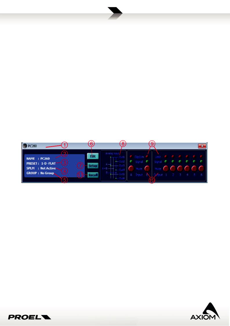
PC260 and PC240 have a similar control panel interface, which differs only for the number of outputs displayed (4 in the PC24, 6 in the PC260). Below there is a brief description of the functions available.
Fig.35 Processor's control panel
1.Device ID and Device type;
2.Device name;
3.Current preset number and current preset name (D = Default, F = Factory preset, P = Protected preset, U = user preset, * = some parameter has been changed in the device and the new modified preset has not be saved yet);
4.SPLM status
5.Group assignment (not present in PC240);
6.Edit panel button: open the DSP edit interface;
7.Setup panel button: open the setup interface;
8.Routing information;
9.Signal LEDs and Clip/Limit LEDs;
10.Mute buttons;
11.Preset Recall button;
23

5.1.2 Active loudspeaker panel
Fig.36 Satellite loudspeaker's control panel.
1.Device ID and Device type;
2.Device name;
3.Group assignment;
4.Current preset number and current preset name (F = Factory preset, U = user preset, * = some parameter has been changed in the device and new modified preset has not be saved yet);
5.Input signal LED and Input limit/comp and clip LED;
6.Output limit LED for High (driver speaker) output and Low (woofer speaker) output;
7.Over Temperature protection LED indication: the device’s amplifier has run over the maximum temperature range so the safety protection occurred and loudspeaker has been muted;
8.Average Power Protection LED indication;
9.Mute button (input mute control, not available for virtual devices);
10.Edit panel button: open the DSP edit interface;
For a complete description of how protections work, please, refer to loudspeaker’s user manuals.
5.1.3 Active subwoofer panel
Fig.37 Subwoofer's control panel.
24
Loading...