


USER'S MANUAL
USER’S MANUAL
MANUALE UTENTE
MANUALE UTENTE
BENUTZERHANDBUCH
MANUEL DE L'UTILISATEUR
MANUAL DEL USUARIO
مدختسملا ليلد
www.proel.com
FCC COMPLIANCE NOTICE
This device complies with part 15 of the FCC rules. Operation is subject to the following two conditions:
(1)This device may not cause harmful interference, and
(2)this device must accept any interference received, including interference that may cause undesired operation.
CAUTION: Changes or modifications not expressly approved by the party responsible for compliance could void the user’s authority to operate the equipment.
NOTE: This equipment has been tested and found to comply with the limits for a Class B digital device, pursuant to part 15 of the FCC Rules. These limits are designed to provide reasonable protection against harmful interference in a residential installation. This equipment generates, uses, and can radiate radio frequency energy and, if not installed and used in accordance with the instruction manual, may cause harmful interference to radio communications. However, there is no guarantee that interference will not occur in a particular installation. If this equipment does cause harmful interference to radio or television reception, which can be determined by turning the equipment off and on, the user is encouraged to try to correct the interference by one or more of the following measures:
•Reorient or relocate the receiving antenna.
•Increase the separation between the equipment and receiver.
•Connect the equipment into an outlet on a circuit different from that to which the receiver is connected.
•Consult the dealer or an experienced radio/TV technician for help.
This marking shown on the product or its literature, indicates that it should not be disposed with other household wastes at the end of its
working life. To prevent possible harm to the enviroment or human health from uncontrolled waste disposal, please separate this from other
types of wastes and recycle it responsibly to promote the sustainable reuse of material resources. Household users should contact either the retailer where they purchased this product, or their local government office, for details of where and how they can take this item for environmentally safe recycling. Business users should contact their supplier and check the terms and conditions of the purchase contract.
This product should not be mixed with other commercial wastes for disposal.
The lightning flash with arrowhead symbol within an equilateral triangle is intended to alert the user to the presence of uninsulated “dangerous voltage” within the product’s enclosure, that may be of sufficient magnitude to constitute a risk of electric shock to persons.
The exclamation point within an equilateral triangle is intended to alert the user to the presence of important operating and maintenance
(servicing) instructions in the literature accompanying the appliance.
The information contained in this publication has been carefully prepared and checked. However no responsibility will be taken for any errors. All rights are reserved and this document cannot be copied, photocopied or reproduced in part or completely without written consent being obtained in advance from PROEL. PROEL reserves the right to make any aesthetic, functional or design modification to any of its products without any prior notice. PROEL assumes no responsibility for the use or application of the products or circuits described herein.
Il marchio riportato sul prodotto o sulla documentazione indica che il prodotto non deve essere smaltito con altri rifiuti domestici al termine del ciclo di vita. Per evitare eventuali danni all’ambiente si invita l’utente a separare questo prodotto da altri tipi di rifiuti e di riciclarlo in maniera responsabile per favorire il riutilizzo sostenibile delle risorse materiali. Gli utenti domestici sono invitati a contattare il rivenditore presso il quale è stato acquistato il prodotto o l’ufficio locale preposto per tutte le informazioni relative alla raccolta differenziata e al riciclaggio per questo tipo di prodotto. Gli utenti aziendali sono invitati a contattare il proprio fornitore e verificare i termini e le condizioni
del contratto di acquisto. Questo prodotto non deve essere smaltito unitamente ad altri rifiuti commerciali.
Il simbolo del lampo con freccia in un triangolo equilatero intende avvertire l'utilizzatore per la presenza di "tensioni pericolose" non isolate all'interno dell'involucro del prodotto, che possono avere una intensità sufficiente a costituire rischio di scossa elettrica alle persone.
Il punto esclamativo in un triangolo equilatero intende avvertire l'utilizzatore per la presenza di importanti istruzioni per l'utilizzo e la manutenzione nella documentazione che accompagna il prodotto.
Le informazioni contenute in questo documento sono state attentamente redatte e controllate. Tuttavia non è assunta alcuna responsabilità per eventuali inesattezze. Tutti i diritti sono riservati e questo documento non può essere copiato, fotocopiato, riprodotto per intero o in parte senza previo consenso scritto della PROEL. PROEL si riserva il diritto di apportare senza preavviso cambiamenti e modifiche estetiche, funzionali o di design a ciascun proprio prodotto. PROEL non assume alcuna responsabilità sull’uso o sul l’applicazione dei prodotti o dei circuiti qui descritti.
Das Kennzeichen auf dem Gerät oder den beiliegenden Unterlagen zeigt an, dass das Gerät am Ende seiner Lebensdauer nicht im Hausmüll
entsorgt werden darf. Aus Umweltschutzgründen bitten wir den Anwender, das Gerät von anderem Müll getrennt zu entsorgen und dem
Recycling zuzuführen, damit die Rohstoffe umweltverträglich wiederverwertet werden können. Private Anwender wenden sich dazu bitte an den Händler, bei dem sie das Produkt gekauft haben, oder an eine örtliche Behörde, die für Informationen zur Mülltrennung und zum Recycling dieser Art von Geräten geben kann. Gewerbliche Anwender werden gebeten, sich an den Zulieferer zu wenden und die
Vertragsbedingungen des Kaufvertrags zu überprüfen. Das Gerät darf nicht zusammen mit anderem Gewerbemüll entsorgt werden.
Das Symbol mit einem Pfeilblitz in einem gleichseitigen Dreieck warnt den Anwender vor „gefährlicher Spannung“ ohne Isolierung im Gehäuse des Geräts. Diese kann hoch genug sein, um Stromschlaggefahr zu verursachen.
Das Ausrufezeichen in einem gleichseitigen Dreieck weist den Anwender auf wichtige Anweisungen zum Gebrauch und zur Instandhaltung des Geräts in den beiligenden Unterlagen hin.
Die Angaben in diesem Dokument wurden sorgfältig zusammengestellt und kontrolliert. Für mögliche Ungenauigkeiten übernehmen wir dennoch keine Haftung. Alle Rechte vorbehalten. Das Dokument darf ohne vorherige schriftliche Genehmigung von PROEL nicht ganz oder in Teilen kopiert oder reproduziert werden. PROEL behält sich das Recht vor, ohne Vorankündigung Änderungen an der Gestaltung, an den Funktionen oder am Design aller ihrer Produkte vorzunehmen. PROEL haftet nicht für den Gebrauch oder die Verwendung der hier beschriebenen Geräte oder elektrischen Systeme.
La marque reportée sur le produit ou sur la documentation indique que l'appareil ne doit pas être éliminé avec d'autres déchets domestiques au terme du cycle de sa vie. Afin d'éviter tout dommage à l'environnement, l'utilisateur est invité à séparer cet appareil des autres types de déchets et de le recycler de manière responsable pour favoriser la réutilisation durable des ressources matérielles. Les utilisateurs domestiques sont invités à contacter le revendeur où l'appareil a été acheté ou le service local préposé afin d'obtenir toutes les informations relatives au tri sélectif et au recyclage pour ce type de produit. Les utilisateurs des entreprises sont invités à contacter leur
fournisseur et à vérifier les termes et les conditions du contrat d'achat. Cet appareil ne doit pas être éliminé avec d'autres déchets commerciaux.
Le symbole d'un éclair avec une flèche dans un triangle équilatéral est destiné à avertir l'utilisateur de la présence de « tensions dangereuses » non isolées dans le boîtier de l'appareil, lesquelles peuvent avoir une intensité suffisante pour constituer un risque de choc électrique pour les personnes.
Le point d'exclamation dans un triangle équilatéral est destiné à avertir l'utilisateur de la présence d'instructions importantes en vue de l'utilisation et de la maintenance de l'appareil dans la documentation qui l'accompagne.
Les informations contenues dans ce document ont été rédigées avec attention et contrôlées. Toutefois, la société PROEL n'assume aucune responsabilité en cas d'inexactitude. Tous les droits sont réservés et ce document ne peut être copié, photocopié, reproduit en entier ou en partie, sans avoir obtenu au préalable le consentement écrit de la société PROEL. PROEL se réserve le droit d'apporter, sans préavis, des changements et des modifications esthétiques, fonctionnelles ou de design à tous ses produits. PROEL n'assume aucune responsabilité quant à l'utilisation ou l'application des appareils ou des circuits décrits dans cette notice.
La marca reproducida en el producto o en la documentación indica que el producto no se debe eliminar con otros desechos domésticos al final de su
ciclo de vida útil. Para evitar posibles daños al medio ambiente se invita al usuario a separar este producto de otros tipos de desechos y reciclarlo
de forma responsable para favorecer el uso sostenible de los recursos materiales. Los usuarios domésticos deben ponerse en contacto con el revendedor donde han comprado el producto o la oficina local encargada, para conocer todas las informaciones correspondientes a la recogida selectiva y al reciclaje para este tipo de producto. Se invita a las empresas a ponerse en contacto con su proveedor y controlar los términos y las
condiciones del contrato de compra. Este producto no se debe eliminar junto con otros desechos comerciales.
El símbolo del relámpago con flecha en un triángulo equilátero tiene la intención de advertir al usuario respecto a la presencia de "tensiones peligrosas" no aisladas dentro de la envoltura del producto, que pueden tener una intensidad suficiente para constituir riesgo de descarga eléctrica a las personas.
El punto exclamativo en un triángulo equilátero tiene la intención de advertir al usuario respecto a la presencia de importantes instrucciones para el uso y el mantenimiento en la documentación que acompaña el producto.
Las informaciones contenidas en este documento se han redactado y controlado atentamente. Sin embargo, el fabricante se exime de toda responsabilidad por posibles inexactitudes. Todos los derechos reservados; por tanto este documento no se puede copiar, fotocopiar, reproducir total o parcialmente sin la autorización previa escrita por parte de PROEL. PROEL si reserva el derecho de realizar sin previo aviso cambios estéticos, funcionales o de diseño a cualquier producto suyo. PROEL no se asume ninguna responsabilidad por el uso o la aplicación de los productos o de los circuitos que se describen aquí.
ىلع رارضأ ةيأ بنجتل .يضارتفلاا هرمع ةياهن يف ىرخلأا ةيلزنملا تايافنلا عم هنم صلختلا متي لا نأ بجي جتنملا نأب قئاثولا ىلع وأ جتنملا ىلع ةروكذملا ةملاعلا لدت |
.داوملا رداصمل ةمادتسملا مادختسلاا ةداعإ ىلع عيجشتلل ةلوؤسم ةقيرطب هريودت ةداعإو تايافنلا نم ىرخلأا عاونلأا نع جتنملا اذه لصفب موقي نأ مدختسملا نم وجرن ةئيبلا |
ةداعإو تايافنلل زيامتملا عمجلاب ةقلعتملا تامولعملا عيمج نع لوؤسملا يلحملا بتكملا وأ هنم جتنملا ءارش مت يذلا ةئزجتلا عئابب اولصتي نأ لزانملا يف نيمدختسملا نم وجرن |
عم جتنملا اذه نم صلختلا مدع بجي .ءارشلا دقع طورشو دونب نم ققحتلاو مهتصاخ دروملاب اولصتي نأ تاكرشلا يف نيمدختسملا نم وجرن .تاجتنملا نم عونلا اذه ريودت |
.ىرخلأا ةيراجتلا تايافنلا |
لكشيل ةيفاك ةوقب دهجلا اذه نوكي نأ نكميو ،جتنملا ةيواح لخاد لوزعم ريغ "ريطخ دهج" دوجو نم مدختسملا ريذحت ينعي علاضلأا يواستم ثلثم يف مهسب قربلا زمر نإ
.صاخشلأل ةيئابرهكلا تامدصلا يف ببستلل ارطخ
.جتنملا عم ةقفرملا قئاثولا يف ةنايصلاو مادختسلال ةمهم تاميلعت دوجو نم مدختسملا ريذحت علاضلأا يواستم ثلثم يف بجعتلا ةملاع ينعت 
ريوصت وأ خسن زوجي لاو ،ةظوفحم قوقحلا عيمج .اهيف ةقدلل صقن يأ نع ةيلوؤسم ةيأ ةكرشلا لمحتت لا ،كلذ عمو .ةيانعب اهنم ققحتلاو ةقيثولا هذه يف ةدراولا تامولعملا دادعإ مت وأ ةيفيظو وأ ةيلامج تلايدعتو تارييغت ةيأ ءارجإ يف قحلاب PROEL ظفتحت .PROEL نم بوتكمو قبسم حيرصت ىلع لوصحلا نودب ايئزج وأ ايلك ةقيثولا هذه جاتنإ ةداعإ وأ
.ةقيثولا هذه يف ةروكذملا رئاودلا وأ تاجتنملا لامعتسا وأ مادختسا نع ةيلوؤسم ةيأ PROEL لمحتت لا .قبسم راذنإ نودب اهتاجتنم نم جتنم يأ ىلع ةيميمصت

INDEX
FCC COMPLIANCE NOTICE.. . . . . . . . . . . . . . . . . . . . . . . . . . . . . . . . . . . . . 2 TECHNICAL SPECIFICATIONS. . . . . . . . . . . . . . . . . . . . . . . . . . . . . . . . . . . 3
SETUP AND RACK MOUNTING (FIG. 1 / 2).. . . . . . . . . . . . . . . . . . . . . . . . 6 LOUDSPEAKER CABLE.. . . . . . . . . . . . . . . . . . . . . . . . . . . . . . . . . . . . . . . . . 6 CONNECTIONS.. . . . . . . . . . . . . . . . . . . . . . . . . . . . . . . . . . . . . . . . . . . . . . . 7 SUGGESTED CONFIGURATIONS. . . . . . . . . . . . . . . . . . . . . . . . . . . . . . . . . 8 LPN FILTER RESPONSE (FIG. 3). . . . . . . . . . . . . . . . . . . . . . . . . . . . . . . . . . 8 CONTROL PANEL (FIG.4) .. . . . . . . . . . . . . . . . . . . . . . . . . . . . . . . . . . . . . . . 9 REAR PANEL (FIG.5).. . . . . . . . . . . . . . . . . . . . . . . . . . . . . . . . . . . . . . . . . . . 9
CONFIGURATION EXAMPLES (FIG.6/7/8). . . . . . . . . . . . . . . . . . . . . . . . . 10 SAFETY AND PRECAUTIONS .. . . . . . . . . . . . . . . . . . . . . . . . . . . . . . . . . . 11 IN CASE OF FAULT .. . . . . . . . . . . . . . . . . . . . . . . . . . . . . . . . . . . . . . . . . . . 11 TROUBLESHOOTING .. . . . . . . . . . . . . . . . . . . . . . . . . . . . . . . . . . . . . . . . . 11 CE CONFORMITY. . . . . . . . . . . . . . . . . . . . . . . . . . . . . . . . . . . . . . . . . . . . . 12 PACKAGING, SHIPPING AND COMPLAINT .. . . . . . . . . . . . . . . . . . . . . . 12 WARRANTY AND PRODUCTS RETURN.. . . . . . . . . . . . . . . . . . . . . . . . . . 12 INSTALLATION AND DISCLAIMER.. . . . . . . . . . . . . . . . . . . . . . . . . . . . . . 12 POWER SUPPLY AND MAINTENANCE.. . . . . . . . . . . . . . . . . . . . . . . . . . 12 GENERAL INFORMATION .. . . . . . . . . . . . . . . . . . . . . . . . . . . . . . . . . . . . . 13 SETUP AND RACK MOUNTING. . . . . . . . . . . . . . . . . . . . . . . . . . . . . . . . . 13 FRONT PANEL (FIG.4).. . . . . . . . . . . . . . . . . . . . . . . . . . . . . . . . . . . . . . . . . 13 REAR PANEL (FIG.5).. . . . . . . . . . . . . . . . . . . . . . . . . . . . . . . . . . . . . . . . . . 14 ADVANCED FEATURES. . . . . . . . . . . . . . . . . . . . . . . . . . . . . . . . . . . . . . . . 16
INDICE
FCC COMPLIANCE NOTICE.. . . . . . . . . . . . . . . . . . . . . . . . . . . . . . . . . . . . . 2 SPECIFICHE TECNICHE .. . . . . . . . . . . . . . . . . . . . . . . . . . . . . . . . . . . . . . . . 3 INSTALLAZIONE A RACK (FIG. 1 / 2). . . . . . . . . . . . . . . . . . . . . . . . . . . . . . 6 CAVO ALTOPARLANTE.. . . . . . . . . . . . . . . . . . . . . . . . . . . . . . . . . . . . . . . . . 6 CONNESSIONI. . . . . . . . . . . . . . . . . . . . . . . . . . . . . . . . . . . . . . . . . . . . . . . . 7 RISPOSTA FILTRO LPN (FIG. 3).. . . . . . . . . . . . . . . . . . . . . . . . . . . . . . . . . . 8 CONFIGURAZIONI SUGGERITE.. . . . . . . . . . . . . . . . . . . . . . . . . . . . . . . . . . 8 PANNELLO DI CONTROLLO (FIG.4).. . . . . . . . . . . . . . . . . . . . . . . . . . . . . . . 9 PANNELLO POSTERIORE (FIG.5).. . . . . . . . . . . . . . . . . . . . . . . . . . . . . . . . . 9
ESEMPI CONFIGURAZIONI (FIG.6/7/8). . . . . . . . . . . . . . . . . . . . . . . . . . . 10
AVVERTENZE PER LA SICUREZZA.. . . . . . . . . . . . . . . . . . . . . . . . . . . . . . 17 IN CASO DI GUASTO .. . . . . . . . . . . . . . . . . . . . . . . . . . . . . . . . . . . . . . . . . 17 PROBLEMATICHE COMUNI.. . . . . . . . . . . . . . . . . . . . . . . . . . . . . . . . . . . . 17 CONFORMITÀ CE .. . . . . . . . . . . . . . . . . . . . . . . . . . . . . . . . . . . . . . . . . . . . 18 IMBALLAGGIO, TRASPORTO E RECLAMI.. . . . . . . . . . . . . . . . . . . . . . . . 18 GARANZIE E RESI.. . . . . . . . . . . . . . . . . . . . . . . . . . . . . . . . . . . . . . . . . . . . 18 INSTALLAZIONE E LIMITAZIONI D’USO .. . . . . . . . . . . . . . . . . . . . . . . . . 18 ALIMENTAZIONE E MANUTENZIONE.. . . . . . . . . . . . . . . . . . . . . . . . . . . 18 INFORMAZIONI GENERALI.. . . . . . . . . . . . . . . . . . . . . . . . . . . . . . . . . . . . 19 INSTALLAZIONE E MONTAGGIO A RACK . . . . . . . . . . . . . . . . . . . . . . . . 19 PANNELLO FRONTALE.. . . . . . . . . . . . . . . . . . . . . . . . . . . . . . . . . . . . . . . . 19 PANNELLO POSTERIORE.. . . . . . . . . . . . . . . . . . . . . . . . . . . . . . . . . . . . . . 20 FUNZIONI AVANZATE .. . . . . . . . . . . . . . . . . . . . . . . . . . . . . . . . . . . . . . . . 22
INHALT
FCC COMPLIANCE NOTICE.. . . . . . . . . . . . . . . . . . . . . . . . . . . . . . . . . . . . . 2 TECHNISCHE DATEN.. . . . . . . . . . . . . . . . . . . . . . . . . . . . . . . . . . . . . . . . . . 5 RACK-INSTALLATION (ABB. 1 / 2).. . . . . . . . . . . . . . . . . . . . . . . . . . . . . . . 6 LAUTSPRECHERKABEL.. . . . . . . . . . . . . . . . . . . . . . . . . . . . . . . . . . . . . . . . 6 ANSCHLÜSSE.. . . . . . . . . . . . . . . . . . . . . . . . . . . . . . . . . . . . . . . . . . . . . . . . 7 EMPFOHLENE KONFIGURATIONEN.. . . . . . . . . . . . . . . . . . . . . . . . . . . . . . 8 FREQUENZGANG FILTER LPN (ABB. 3) .. . . . . . . . . . . . . . . . . . . . . . . . . . . 8 REGLER (ABB.4) .. . . . . . . . . . . . . . . . . . . . . . . . . . . . . . . . . . . . . . . . . . . . . . 9 HINTERE BEDIENTAFEL (ABB.5). . . . . . . . . . . . . . . . . . . . . . . . . . . . . . . . . 9
KONFIGURATIONSBEISPIELE (ABB.6/7/8) .. . . . . . . . . . . . . . . . . . . . . . . 10 SICHERHEITSHINWEISE.. . . . . . . . . . . . . . . . . . . . . . . . . . . . . . . . . . . . . . 23 BEI EINEM DEFEKT. . . . . . . . . . . . . . . . . . . . . . . . . . . . . . . . . . . . . . . . . . . 23 HÄUFIG AUFTRETENDE PROBLEME .. . . . . . . . . . . . . . . . . . . . . . . . . . . . 23 EG-KONFORMITÄT.. . . . . . . . . . . . . . . . . . . . . . . . . . . . . . . . . . . . . . . . . . . 24
VERPACKUNG, TRANSPORT UND REKLAMATIONEN.. . . . . . . . . . . . . . 24 GARANTIE UND RÜCKGABE.. . . . . . . . . . . . . . . . . . . . . . . . . . . . . . . . . . . 24
INSTALLATION UND VERWENDUNGSEINSCHRÄNKUNGEN. . . . . . . . 24 STROMVERSORGUNG UND INSTANDHALTUNG.. . . . . . . . . . . . . . . . . . 24 ALLGEMEINE INFORMATIONEN. . . . . . . . . . . . . . . . . . . . . . . . . . . . . . . . 25 RACK INSTALLATION UND MONTAGE .. . . . . . . . . . . . . . . . . . . . . . . . . . 25 VORDERE BEDIENTAFEL.. . . . . . . . . . . . . . . . . . . . . . . . . . . . . . . . . . . . . . 25 HINTERE BEDIENTAFEL.. . . . . . . . . . . . . . . . . . . . . . . . . . . . . . . . . . . . . . . 26 FORTGESCHRITTENE FUNKTIONEN .. . . . . . . . . . . . . . . . . . . . . . . . . . . . 28
INDEX
FCC COMPLIANCE NOTICE.. . . . . . . . . . . . . . . . . . . . . . . . . . . . . . . . . . . . . 2 SPÉCIFICATIONS TECHNIQUES.. . . . . . . . . . . . . . . . . . . . . . . . . . . . . . . . . 5 INSTALLATION EN RACK (FIG. 1 / 2). . . . . . . . . . . . . . . . . . . . . . . . . . . . . . 6 CÂBLE HAUT-PARLEUR.. . . . . . . . . . . . . . . . . . . . . . . . . . . . . . . . . . . . . . . . 6 CONNEXIONS.. . . . . . . . . . . . . . . . . . . . . . . . . . . . . . . . . . . . . . . . . . . . . . . . 7 RÉPONSE FILTRE LPN (FIG. 3).. . . . . . . . . . . . . . . . . . . . . . . . . . . . . . . . . . . 8 CONFIGURATIONS SUGGÉRÉES.. . . . . . . . . . . . . . . . . . . . . . . . . . . . . . . . . 8 PANNEAU DE COMMANDE (FIG.4) .. . . . . . . . . . . . . . . . . . . . . . . . . . . . . . 9 PANNEAU ARRIÈRE (FIG.5).. . . . . . . . . . . . . . . . . . . . . . . . . . . . . . . . . . . . . 9
EXEMPLES CONFIGURATIONS (FIG.6/7/8). . . . . . . . . . . . . . . . . . . . . . . . 10 MISES EN GARDE DE SÉCURITÉ .. . . . . . . . . . . . . . . . . . . . . . . . . . . . . . . 29 EN CAS DE PANNE.. . . . . . . . . . . . . . . . . . . . . . . . . . . . . . . . . . . . . . . . . . . 29 PROBLÈMES COMMUNS. . . . . . . . . . . . . . . . . . . . . . . . . . . . . . . . . . . . . . 29 CONFORMITÉ CE. . . . . . . . . . . . . . . . . . . . . . . . . . . . . . . . . . . . . . . . . . . . . 30 EMBALLAGE, TRANSPORT ET RÉCLAMATIONS .. . . . . . . . . . . . . . . . . . 30 GARANTIES ET RETOURS.. . . . . . . . . . . . . . . . . . . . . . . . . . . . . . . . . . . . . 30 INSTALLATION ET LIMITES D'UTILISATION.. . . . . . . . . . . . . . . . . . . . . . 30 ALIMENTATION ET MAINTENANCE .. . . . . . . . . . . . . . . . . . . . . . . . . . . . 30 INFORMATIONS GÉNÉRALES.. . . . . . . . . . . . . . . . . . . . . . . . . . . . . . . . . . 31 INSTALLATION ET MONTAGE EN RACK .. . . . . . . . . . . . . . . . . . . . . . . . . 31 PANNEAU AVANT. . . . . . . . . . . . . . . . . . . . . . . . . . . . . . . . . . . . . . . . . . . . 31 PANNEAU ARRIÈRE.. . . . . . . . . . . . . . . . . . . . . . . . . . . . . . . . . . . . . . . . . . 32 FONCTIONS AVANCÉES. . . . . . . . . . . . . . . . . . . . . . . . . . . . . . . . . . . . . . . 34
ÍNDICE
FCC COMPLIANCE NOTICE.. . . . . . . . . . . . . . . . . . . . . . . . . . . . . . . . . . . . . 2 CARACTERÍSTICAS TÉCNICAS.. . . . . . . . . . . . . . . . . . . . . . . . . . . . . . . . . . 5 INSTALACIÓN EN RACK (FIG. 1 / 2).. . . . . . . . . . . . . . . . . . . . . . . . . . . . . . 6 CABLE ALTAVOZ.. . . . . . . . . . . . . . . . . . . . . . . . . . . . . . . . . . . . . . . . . . . . . . 6 CONEXIONES .. . . . . . . . . . . . . . . . . . . . . . . . . . . . . . . . . . . . . . . . . . . . . . . . 7 CONFIGURACIONES SUGERIDAS. . . . . . . . . . . . . . . . . . . . . . . . . . . . . . . . 8 RESPUESTA FILTRO LPN (FIG. 3) .. . . . . . . . . . . . . . . . . . . . . . . . . . . . . . . . 8 PANEL DE CONTROL (FIG.4) .. . . . . . . . . . . . . . . . . . . . . . . . . . . . . . . . . . . . 9 PANEL POSTERIOR (FIG.5). . . . . . . . . . . . . . . . . . . . . . . . . . . . . . . . . . . . . . 9
EJEMPLOS DE CONFIGURACIONES (FIG.6/7/8).. . . . . . . . . . . . . . . . . . . 10
ADVERTENCIAS PARA LA SEGURIDAD. . . . . . . . . . . . . . . . . . . . . . . . . . 35 EN CASO DE AVERÍA.. . . . . . . . . . . . . . . . . . . . . . . . . . . . . . . . . . . . . . . . . 35 PROBLEMAS COMUNES.. . . . . . . . . . . . . . . . . . . . . . . . . . . . . . . . . . . . . . 35 CONFORMIDAD CE.. . . . . . . . . . . . . . . . . . . . . . . . . . . . . . . . . . . . . . . . . . . 36 EMBALAJE, TRANSPORTE Y RECLAMACIONES.. . . . . . . . . . . . . . . . . . 36 GARANTÍAS Y DEVOLUCIONES.. . . . . . . . . . . . . . . . . . . . . . . . . . . . . . . . 36 INSTALACIÓN Y LIMITACIONES DE USO .. . . . . . . . . . . . . . . . . . . . . . . . 36 ALIMENTACIÓN Y MANTENIMIENTO.. . . . . . . . . . . . . . . . . . . . . . . . . . . 36 INFORMACIÓN GENERAL.. . . . . . . . . . . . . . . . . . . . . . . . . . . . . . . . . . . . . 37 INSTALACIÓN Y MONTAJE EN RACK .. . . . . . . . . . . . . . . . . . . . . . . . . . . 37 PANEL FRONTAL.. . . . . . . . . . . . . . . . . . . . . . . . . . . . . . . . . . . . . . . . . . . . . 37 PANEL POSTERIOR.. . . . . . . . . . . . . . . . . . . . . . . . . . . . . . . . . . . . . . . . . . . 38 FUNCIONES AVANZADAS.. . . . . . . . . . . . . . . . . . . . . . . . . . . . . . . . . . . . . 40
سرهفلا
2 . . . . . . . . . . . . . . . . . . . . . . . .FCC COMPLIANCE NOTICE 5 . . . . . . . . . . . . . . . . . . . . . . . . . . . . . . . . . . . . . . . . . . . . . . . . . . . . . . . ةينقتلا تافصاولما
6 . . . . . . . . . . . . . . . . . . . . . . . . . . . . . . . )2 / 1 لكشلا( فر لىع بيكترلا
6 . . . . . . . . . . . . . . . . . . . . . . . . . . . . . . . . . . . . . . . . . . . . . . . . . . . . . . . . . . . . بركلما لبك 7 . . . . . . . . . . . . . . . . . . . . . . . . . . . . . . . . . . . . . . . . . . . . . . . . . . . . . . . . . . . .تلايصوتلا 8 . . . . . . . . . . . . . . . . . . . . . . . . . . . . . . . . . . . . . . . . . . . . . . . . . . . . . . . ةينقتلا تافصاولما
8 . . . . . . . . . . . . . . . . . . . . . . . . . . . . . . . )3 لكشلا( NPL ترلفلا ةباجتسا 9 . . . . . . . . . . . . . . . . . . . . . . . . . . . . . . . . . . . .)4 لكشلا( مكحتلا ةحول 9 . . . . . . . . . . . . . . . . . . . . . . . . . . . . . . . . . . .)5 لكشلا( ةيفلخلا ةحوللا 10 . . . . . . . . . . . . . . . . . . . . . . . )8 / 7 / 6 لكشلا( ةئيهتلا وأ تانيوكتلل ةلثمأ
41 . . . . . . . . . . . . . . . . . . . . . . . . . . . . . . . . . . . . . . . . . . . . . . .ةملاسلاب ةصاخلا تاريذحتلا 41 . . . . . . . . . . . . . . . . . . . . . . . . . . . . . . . . . . . . . . . . . . . . . . . . . . . . . . . . لطعلا ةلاح في 41 . . . . . . . . . . . . . . . . . . . . . . . . . . . . . . . . . . . . . . . . . . . . . . . . . . . . . .ةعئاشلا تلاكشلما
42 . . . . . . . . . . . . . . . . . . . . . . . . . . . . . . . . . . . . . . . . . EC ةقباطم
42 . . . . . . . . . . . . . . . . . . . . . . . . . . . . . . . . . . . . . . . . . ىواكشلاو لقنلاو فيلغتلاو ةئبعتلا 42 . . . . . . . . . . . . . . . . . . . . . . . . . . . . . . . . . . . . . . . . . . . . . . . . . . . . . . .دئاوعلاو نماضلا 42 . . . . . . . . . . . . . . . . . . . . . . . . . . . . . . . . . . . . . . . . . . . . مادختسلاا لىع دويقلاو بيكترلا 42 . . . . . . . . . . . . . . . . . . . . . . . . . . . . . . . . . . . . . . . . . . . . . . . . . . . . . . .ةنايصلاو ةيذغتلا 43 . . . . . . . . . . . . . . . . . . . . . . . . . . . . . . . . . . . . . . . . . . . . . . . . . . . . . . . .ةماع تامولعم 43 . . . . . . . . . . . . . . . . . . . . . . . . . . . . . . . . . . . . . . . . . . . . . . . فر لىع عيمجتلاو بيكترلا 43 . . . . . . . . . . . . . . . . . . . . . . . . . . . . . . . . . . . . . . . . . . . . . . . . . . . . . . . .ةيماملأا ةحوللا 44 . . . . . . . . . . . . . . . . . . . . . . . . . . . . . . . . . . . . . . . . . . . . . . . . . . . . . . . .ةيفلخلا ةحوللا 46 . . . . . . . . . . . . . . . . . . . . . . . . . . . . . . . . . . . . . . . . . . . . . . . . . . . . . .ةمدقتلما فئاظولا
4 |
Index |

TECHNICAL SPECIFICATIONS |
SPECIFICHE TECNICHE |
TECHNISCHE DATEN |
|
|||
|
|
|
|
|
|
|
SPÉCIFICATIONS TECHNIQUES |
CARACTERÍSTICAS TÉCNICAS |
ةينقتلاتافصاوملا |
|
|||
MODEL |
|
HPX900 |
HPX1200 |
HPX2400 |
HPX2800 |
|
|
|
|
|
|
|
|
Power 8 ohm * |
|
200 W |
300 W |
450 W |
600 W |
|
Power 4 ohm * |
|
300 W |
450 W |
800 W |
1000 W |
|
Power 2 ohm ** |
|
450 W |
600 W |
1200 W |
1400 W |
|
Power BRIDGE 8 ohm * |
|
600 W |
900 W |
1600 W |
2000 W |
|
Power BRIDGE 4 ohm ** |
|
900 W |
1200 W |
2400 W |
2800 W |
|
Output Stage |
|
Class AB |
Class AB |
Class H |
Class H |
|
Frequency response (+0/-0.5 dB) |
|
20 Hz - 20 KHz |
20 Hz - 20 KHz |
20 Hz - 20 KHz |
20 Hz - 20 KHz |
|
Input Sensitivity (nominal) |
+2.3 dBu / 1.0 Vrms |
+1.0 dBu / 0.87 Vrms |
+0.8 dBu / 0.85 Vrms |
0 dBu / 0.775Vrms |
|
|
Input Sensitivity (fixed gain) |
+8.3 dBu / 2.02 Vrms |
+4.0 dBu / 1.23 Vrms |
+5.8 dBu / 1.51 Vrms |
+7.0 dBu / 1.73 Vrms |
|
|
GAIN (nominal/fixed) |
32 dB (40x) / 26 dB (20x) |
35 dB (56x) / 32 dB (40x) |
37 dB (71x) / 32 dB (40x) |
39 dB (89x) / 32 dB (40x) |
|
|
Input Connectors / Impedance |
|
|
XLR M, 1/4" JACK, RCA / 20 Kohm (balanced), 10 Kohm (unbalanced) |
|
|
|
Output Connectors |
|
|
SPEAKON and Binding Post |
|
|
|
Damping Factor |
|
> 100 |
> 100 |
> 200 |
> 200 |
|
Slew Rate |
|
> 20 V/uS |
> 20 V/uS |
> 20 V/uS |
> 20 V/uS |
|
S/N Ratio (unweighted) |
|
> 85 dB |
> 86 dB |
> 90 dB |
> 91 dB |
|
THD+N |
|
< 0.1% |
< 0.1% |
< 0.1% |
< 0.1% |
|
Controls |
|
INPUT LEVEL, INPUT SENSITIVITY, STEREO/BRIDGE/PARALLEL, LOW PASS NOTCH (LPN), GND LIFT |
|
|||
LED Indicators |
|
|
POWER, ON, PARALLEL, BRIDGE, SIGNAL, LIMIT, PROTECT |
|
|
|
Cooling |
|
|
Variable speed DC fan |
|
|
|
Protections |
|
|
AC low power, DC, thermal, |
short circuit, VHF, CLIP limiter |
|
|
Mains Supply Voltage |
|
|
230 VAC (±10%) 50/60 Hz or 120VAC (±10%) 50/60 Hz |
|
|
|
Maximum Consumption |
|
642 VA |
890 VA |
1180 VA |
1489 VA |
|
Rated Consumption *** |
|
248 VA |
357 VA |
290 VA |
370 VA |
|
Standby Consumption |
|
3.5 VA |
3.5 VA |
3.5 VA |
3.5 VA |
|
Dimensions (W x H x D) |
483 x 89 x 335 mm |
483 x 89 x 395 mm |
483 x 89 x 395 mm |
483 x 89 x 395 mm |
|
|
|
19" x 3.5" x 13.2" (2U rack) |
19" x 3.5" x 15.6" (2U rack) |
19" x 3.5" x 15.6" (2U rack) |
19" x 3.5" x 15.6" (2U rack) |
|
|
Weight |
|
6 Kg (13.2 lb) |
6.9 Kg (15.2 lb) |
9.2 Kg (20.3 lb) |
9.2 Kg (20.3 lb) |
|
*RMS both channel THD < 1%
**40 ms burst
***Rated consumption is measured with pink noise with a crest factor of 12 dB, this can be considered a standard music program.
Specifications |
5 |
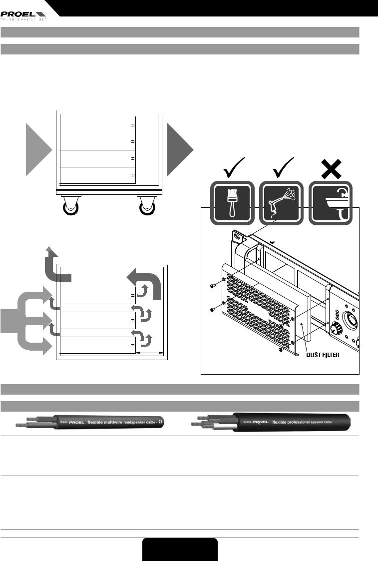
SETUP AND RACK MOUNTING (FIG. 1 / 2) INSTALLATION EN RACK (FIG. 1 / 2)
INSTALLAZIONE A RACK (FIG. 1 / 2) |
RACK-INSTALLATION (ABB. 1 / 2) |
INSTALACIÓN EN RACK (FIG. 1 / 2) |
)2ةينقتلا/ 1 لكشلا(تافصاوملافر ىلع بيكرتلا |
|
|
|
RECOMMENDED INSTALLATION |
|
|
|
|
|
|
|
|||||
FIG.1 |
|
INSTALLAZIONE RACCOMANDATA |
|
|
|
|
|
|
|
||||||
|
EMPFOHLENE INSTALLATION |
|
|
|
|
|
|
|
|||||||
|
|
|
RECOMMENDED INSTALLATION |
|
|
|
|
|
|
|
|
||||
|
FRONT |
|
INSTALLATION RECOMMANDÉE |
|
|
REAR |
|
|
|
|
|||||
|
|
INSTALACIÓN RECOMENDADA |
|
|
|
|
|
|
|||||||
|
FRONTALE |
|
INSTALLAZIONE RACCOMANDATA |
|
|
POSTERIORE |
|
|
|
|
|||||
|
VORDERSEITIG |
هب صىولما بيكترلا |
|
|
RÜCKSEITIG |
|
|
|
|
||||||
|
AVANT |
FRONT |
|
|
|
REAR |
|
ARRIÈRE |
|
|
|
|
|||
|
FRONTAL |
|
|
|
|
POSTERIOR |
|
|
|
|
|||||
|
يمامأ |
FRONTALE |
POSTERIORE |
|
يفلخ |
|
|
|
|
||||||
|
|
|
|
|
|
|
|
|
|||||||
COLD AIR |
|
|
|
|
|
|
|
HOT AIR |
|
|
|
HOT AIR |
|
||
|
|
|
|
|
|
|
|
|
|
||||||
|
|
|
|
|
|
|
|
|
|
ARIA CALDA |
|
||||
|
|
|
|
|
|
|
|
||||||||
|
|
|
|
|
|
|
|
|
|
|
|
|
|
WARMLUFT |
|
|
|
|
|
|
|
|
|
|
|
|
|
|
|
|
|
|
|
|
|
|
|
|
|
|
|
|
|
|
|
AIR CHAUD |
|
|
|
|
|
|
|
|
|
|
|
|
|
|
AIRE CALIENTE |
|
|
|
|
|
|
|
|
|
|
|
|
|
|
|
|
نخاس ءاوه |
FIG.2 |
|
|
|
|
|
|
|
|
|
|
|
|
|
|
|
|
|
|
|
|
|
|
|
|
|
|
|
|
|
|
|
|
|
|
|
|
|
|
|
|
|
|
|
|
|
|
|
|
COLD AIR |
|
|
|
|
|
|
|
ARIA CALDA |
|
ARIA FREDDA |
|
|
|
|
|
|
|
|
|
ARIA FREDDA |
|
|
|
|
|
|
|
|
|
KALTLUFT |
|
|
|
|
|
|
|
|
|
AIR FROID |
|
|
8U |
RACK |
|
|
|
|
|
AIRE FRÍO |
|
|
RACK aperto 8U |
|
|
|
|
|
|
|
|
8U OPEN RACK |
|
|
|
|
|||
دراب ءاوه |
|
|
RACK offen 8U |
8U |
|
|
|
|
|
|
|
|
ouvert 8U |
|
|
|
|
||
|
|
RACKRACK abiertoaperto8U |
|
|
|
|
|||
|
|
|
RACK حوتفم8U |
|
|
|
|
|
|
|
|
|
EVENTUAL INSTALLATION WITH CLOSED BACK |
|
|
|
|||
|
|
|
EVENTUALE INSTALLAZIONE CON RETRO CHIUSO |
|
BACK |
|
|||
HOT AIR |
EVENTUALMÖGLICHEINSTALLATIONMIT GESCHLOSSENERWITH CLOSEDRÜCKSEITE |
|
|||||||
ARIA CALDA |
|
|
INSTALLATION ÉVENTUELLE AVEC ARRIÈRE FERMÉ |
|
|
|
|||
WARMLUFT |
EVENTUALEPOSIBLEINSTALLAZIONEINSTALACIÓN CON PARTE POSTERIORCON RETROCERRADA |
CHIUSO |
|
||||||
AIR CHAUDHOT AIR |
|
||||||||
AIRE CALIENTE |
|
|
قلغم يفلخ حولب بيكرتلا ةلاح يف |
|
|
|
|
||
ARIA CALDA |
FRONT |
|
|
|
REAR (closed) |
|
|||
|
|
|
|
|
|||||
|
|
|
|
POSTERIORE (chiuso) |
|
||||
نخاس ءاوه |
|
VORDERSEITIG |
|
|
|
|
|||
|
|
|
|
|
RÜCKSEITIG (geschlossen) |
|
|||
|
|
FRONTALE |
|
|
|
||||
|
|
|
REAR (closed) |
|
|||||
|
|
AVANT |
|
|
|
ARRIÈRE (fermé) |
|
||
|
|
FRONTALE |
|
|
POSTERIOR (cerrado) |
|
|||
|
|
POSTERIORE (chiuso) |
|
||||||
|
|
يمامأ |
|
|
|
)قلغم( يفلخ |
|
||
COLD AIR |
|
|
|
|
|
|
|
|
|
COLD AIR |
|
|
|
|
|
|
|
|
|
ARIA FREDDA |
|
|
|
|
|
|
|
|
|
ARIA FREDDA |
|
|
|
|
|
15 cm |
|
|
|
KALTLUFT |
|
|
10U CLOSED AIR |
|
|
|
|||
AIR FROID |
|
|
RACK chiuso 10U |
|
|
|
|||
AIRE FRÍO |
|
|
10U closed RACK |
6 inch |
|
|
|||
|
|
RACK geschlossen 10U |
|
|
|
||||
دراب ءاوه |
|
|
RACK fermé 10U |
|
|
|
|||
|
|
RACK chiuso 10U |
|
|
|
|
|||
|
|
|
RACK cerrado 8U |
|
|
|
|
|
|
|
|
|
RACK قلغم8U |
|
|
|
|
|
|
LOUDSPEAKER CABLE |
|
CAVO ALTOPARLANTE |
LAUTSPRECHERKABEL |
||||||
CÂBLE HAUT-PARLEUR |
|
CABLE ALTAVOZ |
ربكملاةينقتالبكتافصاوملا |
||||||
ENGLISH: Loudspeaker Line Losses (maximum permissible line lengths for 0.5dB losses, voltage or spl)
ITALIANO: Perdite di collegamento linee Altoparlanti (massima lunghezza possibile per perdite inferiori a 0.5dB, tensione o spl)
DEUTSCH: Leitungsverluste Lautsprecherlinien (größtmögliche Länge für Verluste von maximal 0.5dB, Spannung oder spl)
FRANÇAIS: Pertes de connexion lignes haut-parleurs (longueur maximale possible pour pertes inférieures à 0,5 dB, tension ou spl)
ESPAÑOL: Pérdidas de conexión líneas Altavoces (longitud máxima posible para pérdidas inferiores a 0.5 dB, tensión o spl)
AR
4 ohm load |
8 ohm load |
Wire section data |
PROEL recommended cables |
|
|
||||
|
|
|
|
|
|
|
|
|
|
feet |
meter |
feet |
meter |
mm² |
AWG |
2 wires |
4 wires |
2 wires Fire-resistant |
4 wires Fire-resistant |
|
|
|
|
|
|
|
|
|
|
75 |
25 |
150 |
50 |
4.0 |
12 |
HPC624 |
HPC644 |
HPC624FR |
|
|
|
|
|
|
|
|
|
|
|
50 |
17.5 |
100 |
35 |
2.0 |
14 |
HPC620 |
HPC640 |
HPC520 |
HPC540 |
|
|
|
|
|
|
|
|
|
|
30 |
10 |
60 |
20 |
1.5 |
16 |
HPC610 |
|
HPC510 |
|
|
|
|
|
|
|
|
|
|
|
20 |
7.5 |
40 |
15 |
1.0 |
18 |
HPC605 |
|
|
|
this is a short extraction of the wide assortment of cables available from PROEL, please visit our website at www.proelgroup.com
6 |
FIG. 1 / 2 |
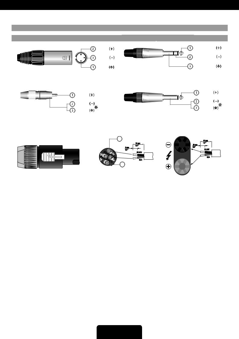
CONNECTIONS |
|
|
CONNESSIONI |
|
|
|
|
ANSCHLÜSSE |
|||
CONNEXIONS |
|
|
CONEXIONES |
|
|
|
|
تلايصوتلاةينقتلاتافصاوملا |
|||
|
|
|
hot |
|
|
|
|
|
|
|
tip - hot |
|
|
|
cold |
|
|
|
|
|
|
|
ring - cold |
|
|
|
ground |
|
INPUT |
|
|
|
|
|
sleeve - gnd |
|
|
|
|
|
|
INPUT (Eingang) |
INPUT (ingresso) |
||||
|
|
|
|
INPUT |
|
|
INPUT (entrada) |
||||
INPUT |
INPUT (Eingang) |
|
INPUT (entrada) |
Jack (balanced) |
|
Klinkenstecker (symmetrisch) |
Jack (balanceado) |
||||
INPUT |
|
INPUT (ingresso) |
|
Jack (balanced) |
|
|
|
Jack (bilanciato) |
|||
Balanced male XLR |
XLR symmetrisch, männlich |
XLR balanceado macho |
|
INPUT (entrée) |
|
||||||
INPUT (ingresso) |
|
|
|
INPUT (لخدم\ |
|||||||
INPUT (ingresso) |
INPUT (entrée) |
XLR |
INPUT (لخدم\ |
Jack (bilanciato) |
|
Jack (symétrique) |
|
)نزاوتم( توص لصومّ |
|||
Balanced male XLR |
bilanciato maschio |
|
|
|
|
|
|
|
|
||
XLR bilanciato maschio |
XLR symétrique mâle |
XLRركذنزاوتم |
|
|
|
|
|
|
|
|
|
|
|
|
hot |
|
|
|
|
|
|
|
tip - hot |
|
|
|
|
|
|
|
|
|
|
|
|
|
|
|
cold |
|
|
|
|
|
|
|
cold |
|
|
|
|
|
|
|
|
|
|
ground |
|
|
|
|
ground |
|
|
|
|
|
|
|
|
|
|
|
|
INPUT |
|
|
INPUT (Eingang) |
|
INPUT (entrada) |
||
INPUT |
INPUT |
|
INPUT |
|
|
|
|
||||
|
|
Jack (unbalanced) |
|
Klinkenstecker (unsymmetrisch) |
Jack (desbalanceado) |
||||||
RCA (unbalanced) |
RCA (unsymmetrisch) |
RCA (desbalanceado) |
|
|
|||||||
INPUT |
|
INPUT (ingresso) |
|
INPUT(ingresso) |
|
INPUT (entrée) |
INPUT INPUT(ingresso)(لخدم\ |
||||
INPUT |
INPUT |
|
INPUT |
|
Jack (sbilanciato) |
|
Jack (asymétrique) |
|
نزاوتمريغ( توصلصومّ |
||
RCARCA(sbilanciato)(unbalanced) |
RCA (asymétrique) |
RCA (sbilanciato)RCA يزاوتم ريغ |
|
Jack (unbalanced) |
|
|
Jack (sbilanciato) |
||||
|
|
|
|
|
|
*note: connect both cold and ground to make cable from balanced to unbalanced |
|||||
|
|
|
|
|
|
*nota: connettere insieme cold e ground per cavi da bilanciato a sbilanciato |
|||||
|
|
|
|
|
*note:*Hinweis:connectbei Verbindungboth coldvonandsymmetrischgroundzu unsymmetrisch*nota:Kaltconnettereund Masse zusammeninsiemeanschließencold ground |
||||||
|
|
|
|
|
*remarque : connecter ensemble cold et ground pour des câbles de symétrique à asymétrique |
||||||
|
|
|
|
|
to make cable from balanced to unbalanced |
per cavi da bilanciato a sbilanciato |
|||||
|
|
|
|
|
|
*nota: conecte juntos cold y ground para cables de balanceado a desbalanceado |
|||||
|
|
|
|
1- |
negative/ |
|
نزاوتملاريغىتحونزاوتملانمةيادبتلاباكلل ًاعميضرلأاودرابلاطبرا:*!هبتنا |
||||
|
|
|
|
/ black / nero |
دوسأ |
|
|
||||
|
|
|
|
|
black / nero /schwarz / noir /es / |
|
|
40 mm |
|||
|
|
|
|
|
|
|
|
|
|
|
|
|
|
|
|
|
20 mm |
|
|
|
|
1.6 " |
|
|
|
|
|
|
0.8 " |
|
|
|
|
15 mm |
|
|
|
|
|
|
|
|
|
|
0.6 " |
||
|
|
|
|
|
8 mm |
|
|
|
|
|
|
|
|
|
n.c.2+ |
1- |
0.3 " |
|
|
|
|
|
BLACK |
|
|
|
BLACK |
|
|
|
|
|
|||
2- |
|
RED |
1+ |
RED |
|
n.c. |
1+ |
positive / red / rosso |
|
positive / red / rosso /rot / rouge /es /رمحأ |
SPEAKER POWER OUTPUTS |
POWER OUTPUT - uscite |
|
|
|
PROEL code - NL4FX |
POST speaker output |
|||
NeutrikSPEAKERNL4 SpeakonPOWERCable ConnectorOUTPUTS |
altoparlanti |
PROEL code - NL4FX |
BINDING POST speaker output |
|
POWER OUTPUT - uscite altoparlanti |
Connettore per cavo tipo Speakon |
Codice PROEL - NL4FX |
uscite altoparlanti BINDING POST |
|
Neutrik NL4 Speakon Cable Connector |
Neutrik NL4 |
Codice PROEL - NL4FX |
uscite altoparlanti BINDING POST |
|
Connettore per cavo tipo Speakon Neutrik NL4 |
|
PROEL-Code - NL4FX |
Lautsprecherausgänge BINDING POST |
|
POWER OUTPUT - Lautsprecherausgänge |
|
Code PROEL - NL4FX |
sorties haut-parleurs BINDING POST |
|
Anschluss für Kabel vom Typ Speakon Neutrik NL4 |
|
Código PROEL - NL4FX |
salidas altavoces BINDING POST |
|
POWER OUTPUT - sorties haut-parleurs |
|
PROEL - NL4FX دوك |
|
BINDING POST توص تابركم جراخم |
Connecteur pour câble type Speakon Neutrik NL4 |
|
|
||
POWER OUTPUT - salidas de los altavoces
Conector para cable de tipo Speakon Neutrik NL4AR
توصلا تاّٜركم جراخم – ةيتوص ةوق جرخم
Speakon Neutrik NL4 ةيعون لباك لصومّر
Connections |
7 |

SUGGESTED CONFIGURATIONS |
CONFIGURAZIONI SUGGERITE |
This table is a shortform of some sound system examples composed of PROEL loudspeakers. These are a few portion of the speaker products in catalogue at the moment of printing.
|
|
AMPLIFIERS |
|
set as: |
example |
||
|
HPX900 |
HPX1200 |
HPX2400 |
HPX2800 |
figures: |
||
|
|
|
|||||
|
4x FLASH5P |
2x FLASH15P |
2x NET15P |
2x SW118P |
|
|
|
|
2x FLASH8P |
2x EX215P4 |
2x NET215P4 |
2x NEOS122P |
STEREO or |
PARALLEL |
|
|
2x FLASH12P |
2x EX18SP |
2x NEOS15P |
|
|
||
|
2x EX15P/MP |
2x EX218SP4 |
|
|
6 |
||
LOUDSPEAKERS |
2x EX15SP |
2x NET12P |
|
|
|
||
2x NET10P |
2x SW115P |
|
|
|
|||
|
|
|
|
|
|||
2x NEOS10P |
2x NEOS12P |
|
|
|
|
|
|
1x NET15P |
1x NEOS122P |
1x NEOS152P |
1x NEOS218SP |
BRIDGE |
|
||
1x NEOS15P |
1x SW118P |
1x NEOS118SP |
|
7 |
|||
|
|
1x NEOS215SP |
|
|
|||
|
|
|
|
|
|
|
|
|
2x SW110P + |
2x SW115P + |
|
|
STEREO |
systems |
|
|
2x FLASH5P |
2x FLASH8P |
|
|
8 |
||
|
|
2x SW115P + |
|
|
|||
|
|
|
|
|
|||
|
|
2x FLASH8P |
|
|
|
||
|
|
|
|
|
|
|
|
Questa tabella è un riassunto di alcuni esempi di sistema c o m p o s t i c o n altoparlanti PROEL. Questa è una porzione degli altoparlanti in catalogo al momento della stampa.
EMPFOHLENE KONFIGURATIONEN |
CONFIGURATIONS SUGGÉRÉES |
Diese Tabelle ist eine Zusammenfassung einiger Ce tableau est un résumé de certains exemples de système
Systembeispiele mit PROEL-Lautsprechern. Dies ist ein composés avec des haut-parleurs PROEL. Il s'agit d'une Lautsprecherteil im Katalog beim Druck. partie des haut-parleurs au catalogue au moment de
l'impression.
CONFIGURACIONES SUGERIDAS |
ةحرتقملا تانيوكتلا |
Esta tabla es un resumen de algunos ejemplos de sistemas تاربكم عم تابكرملا ماظن ىلع ةلثملأا ضعبل صخلم نع ةرابع لودجلا اذه compuestos por altavoces PROEL. Esta es una porción de .ةعابطلا تقو يف جولاتكلا يف ةدوجوملا تاربكملا نم ءزج اذه .PROEL los altavoces en catálogo en el momento de la impresión.
LPN FILTER RESPONSE (FIG. 3) |
RISPOSTA FILTRO LPN (FIG. 3) |
FREQUENZGANG FILTER LPN (ABB. 3) |
RÉPONSE FILTRE LPN (FIG. 3) |
RESPUESTA FILTRO LPN (FIG. 3) |
)3ةينقتلالكشلا(تافصاوملاLPN رتلفلا ةباجتسا |
+15 |
|
|
|
|
|
+12 |
|
|
|
|
|
+9 |
|
|
|
|
|
+6 |
|
|
|
|
|
+3 |
|
|
|
|
|
dB 0 |
|
|
|
|
|
-3 |
|
|
|
|
|
-6 |
|
|
|
|
|
-9 |
|
|
|
|
|
-12 |
|
|
|
|
|
-15 20 |
100 |
f (Hz) |
1K |
10K |
20K |
|
|
|
|
|
8 |
Connections |
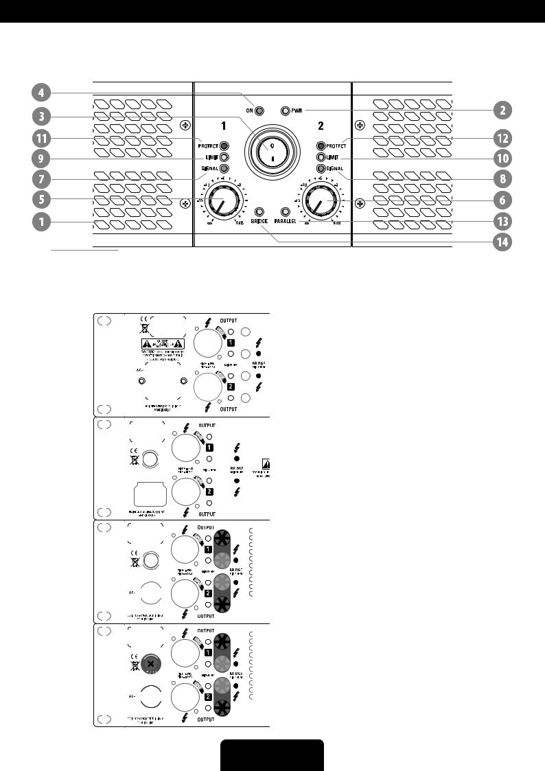
CONTROL PANEL (FIG.4) |
PANNELLO DI CONTROLLO (FIG.4) |
REGLER (ABB.4) |
PANNEAU DE COMMANDE (FIG.4) |
PANEL DE CONTROL (FIG.4) |
)4ةينقتلالكشلا(تافصاوملامكحتلا ةحول |
REAR PANEL (FIG.5) |
PANNELLO POSTERIORE (FIG.5) |
HINTERE BEDIENTAFEL (ABB.5) |
PANNEAU ARRIÈRE (FIG.5) |
PANEL POSTERIOR (FIG.5) |
)5ةينقتلالكشلا(تافصاوملاةيفلخلا ةحوللا |
|
|
|
|
|
|
|
|
|
|
|
|
|
|
|
|
|
|
|
|
|
|
|
|
|
|
|
|
|
|
|
|
|
|
|
|
|
|
|
|
|
|
|
|
|
|
|
|
|
|
|
|
|
|
|
|
|
|
|
|
|
|
|
|
|
|
|
|
|
|
|
|
|
|
|
|
|
|
|
|
|
|
|
|
|
|
|
|
|
|
|
|
|
|
|
|
|
|
|
|
|
|
|
|
|
|
|
|
|
|
|
|
|
|
|
|
|
|
|
|
|
|
|
|
|
|
|
|
|
|
|
|
|
|
|
|
|
|
|
|
|
|
|
|
|
|
|
|
|
|
|
|
|
|
|
|
|
|
|
|
|
|
|
|
|
|
|
|
|
|
|
|
|
|
|
|
|
|
|
|
|
|
|
|
|
|
|
|
|
|
|
|
|
|
|
|
|
|
|
|
|
|
|
|
|
|
|
|
|
|
|
|
|
|
|
|
|
|
|
|
|
|
|
|
|
|
|
|
|
|
|
|
|
|
|
|
|
|
|
|
|
|
|
|
|
|
|
|
|
|
|
|
|
|
|
|
|
|
|
|
|
|
|
|
|
|
|
|
|
|
|
|
|
|
|
|
|
|
|
|
|
|
|
|
|
|
|
|
|
|
|
|
|
|
|
|
|
|
|
|
|
|
|
|
|
|
|
|
|
|
|
|
|
|
|
|
|
|
|
|
|
|
|
|
|
|
|
|
|
|
|
|
|
|
|
|
|
|
|
|
|
|
|
|
|
|
|
|
|
|
|
|
|
|
|
|
|
|
|
|
|
|
|
|
|
|
|
|
|
|
|
|
|
|
|
|
|
|
|
|
|
|
|
|
|
|
|
|
|
|
|
|
|
|
|
|
|
|
|
|
|
|
|
|
|
|
|
|
|
|
|
|
|
|
|
|
|
|
|
|
|
|
|
|
|
|
|
|
|
|
|
|
|
|
|
|
|
|
|
|
|
|
|
|
|
|
|
|
|
|
|
|
|
|
|
|
|
|
|
|
|
|
|
|
|
|
|
|
|
|
|
|
|
|
|
|
|
|
|
|
|
|
|
|
|
|
|
|
|
|
|
|
|
|
|
|
|
|
|
|
|
|
|
|
|
|
|
|
|
|
|
|
|
|
|
|
|
|
|
|
|
|
|
|
|
|
|
|
|
|
|
|
|
|
|
|
|
|
|
|
|
|
|
|
|
|
|
|
|
|
|
|
|
|
|
|
|
|
|
|
|
|
|
|
|
|
|
|
|
|
|
|
|
|
|
|
|
|
|
|
|
|
|
|
|
|
|
|
|
|
|
|
|
|
|
|
|
|
|
|
|
|
|
|
|
|
|
|
|
|
|
|
|
|
|
|
|
|
|
|
|
|
|
|
|
|
|
|
|
|
|
|
|
|
|
|
|
|
|
|
|
|
|
|
|
|
|
|
|
|
|
|
|
|
|
|
|
|
|
|
|
|
|
|
|
|
|
|
|
|
|
|
|
|
|
|
|
|
|
|
|
|
|
|
|
|
|
|
|
|
|
|
|
|
|
|
|
|
|
|
|
|
|
|
|
|
|
|
|
|
|
|
|
|
|
|
|
|
|
|
|
|
|
|
|
|
|
|
|
|
|
|
|
|
|
|
|
|
|
|
|
|
|
|
|
|
|
|
|
|
|
|
|
|
|
|
|
|
|
|
|
|
|
|
|
|
|
|
|
|
|
|
|
|
|
|
|
|
|
|
|
|
|
|
|
|
|
|
|
|
|
|
|
|
|
|
|
|
|
|
|
|
|
|
|
|
|
|
|
|
|
|
|
|
|
|
|
|
|
|
|
|
|
|
|
|
|
|
|
|
|
|
|
|
|
|
|
|
|
|
|
|
|
|
|
|
|
|
|
|
|
|
|
|
|
|
|
|
|
|
|
|
|
|
|
|
|
|
|
|
|
|
|
|
|
|
|
|
|
|
|
|
|
|
|
|
|
|
|
|
|
|
|
|
|
|
|
|
|
|
|
|
|
|
|
|
|
|
|
|
|
|
|
|
|
|
|
|
|
|
|
|
|
|
|
|
|
|
|
|
|
|
|
|
|
|
|
|
|
|
|
|
|
|
|
|
|
|
|
|
|
|
|
|
|
|
|
|
|
|
|
|
|
|
|
|
|
|
|
|
|
|
|
|
|
|
|
|
|
|
|
|
|
|
|
|
|
|
|
|
|
|
|
|
|
|
|
|
|
|
|
|
|
|
|
|
|
|
|
|
|
|
|
|
|
|
|
|
|
|
|
|
|
|
|
|
|
|
|
|
|
|
|
|
|
|
|
|
|
|
|
|
|
|
|
|
|
|
|
|
|
|
|
|
|
|
|
|
|
|
|
|
|
|
|
|
|
|
|
|
|
|
|
|
|
|
|
|
|
|
|
|
|
|
|
|
|
|
|
|
|
|
|
|
|
|
|
|
|
|
|
|
|
|
|
|
|
|
|
|
|
|
|
|
|
|
|
|
|
|
|
|
|
|
|
|
|
|
|
|
|
|
|
|
|
|
|
|
|
|
|
|
|
|
|
|
|
|
|
|
|
|
|
|
|
|
|
|
|
|
|
|
|
|
|
|
|
|
|
|
|
|
|
|
|
|
|
|
|
|
|
|
|
|
|
|
|
|
|
|
|
|
|
|
|
|
|
|
|
|
|
|
|
|
|
|
|
|
|
|
|
|
|
|
|
|
|
|
|
|
|
|
|
|
|
|
|
|
|
|
|
|
|
|
|
|
|
|
|
|
|
|
|
|
|
|
|
|
|
|
|
|
|
|
|
|
|
|
|
|
|
|
|
|
|
|
|
|
|
|
|
|
|
|
|
|
|
|
|
|
|
|
|
|
|
|
|
|
|
|
|
|
|
|
|
|
|
|
|
|
|
|
|
|
|
|
|
|
|
|
|
|
|
|
|
|
|
|
|
|
|
|
|
|
|
|
|
|
|
|
|
|
|
|
|
|
|
|
|
|
|
|
|
|
|
|
|
|
|
|
|
|
|
|
|
|
|
|
|
|
|
|
|
|
|
|
|
|
|
|
|
|
|
|
|
|
|
|
|
|
|
|
|
|
|
|
|
|
|
|
|
|
|
|
|
|
|
|
|
|
|
|
|
|
|
|
|
|
|
|
|
|
|
|
|
|
|
|
|
|
|
|
|
|
|
|
|
|
|
|
|
|
|
|
|
|
|
|
|
|
|
|
|
|
|
|
|
|
|
|
|
|
|
|
|
|
|
|
|
|
|
|
|
|
|
|
|
|
|
|
|
|
|
|
|
|
|
|
|
|
|
|
|
|
|
|
|
|
|
|
|
|
|
|
|
|
|
|
|
|
|
|
|
|
|
|
|
|
|
|
|
|
|
|
|
|
|
|
|
|
|
|
|
|
|
|
|
|
|
|
|
|
|
|
|
|
|
|
|
|
|
|
|
|
|
|
|
|
|
|
|
|
|
|
|
|
|
|
|
|
|
|
|
|
|
|
|
|
|
|
|
|
|
|
|
|
|
|
|
|
|
|
|
|
|
|
|
|
|
|
|
|
|
|
|
|
|
|
|
|
|
|
|
|
|
|
|
|
|
|
|
|
|
|
|
|
|
|
|
|
|
|
|
|
|
|
|
|
|
|
|
|
|
|
|
|
|
|
|
|
|
|
|
|
|
|
|
|
|
|
|
|
|
|
|
|
|
|
|
|
|
|
|
|
|
|
|
|
|
|
|
|
|
|
|
|
|
|
|
|
|
|
|
|
|
|
|
|
|
|
|
|
|
|
|
|
|
|
|
|
|
|
|
|
|
|
|
|
|
|
|
|
|
|
|
|
|
|
|
|
|
|
|
|
|
|
|
|
|
|
|
|
|
|
|
|
|
|
|
|
|
|
|
|
|
|
|
|
|
|
|
|
|
|
|
|
|
|
|
|
|
|
|
|
|
|
|
|
|
|
|
|
|
|
|
|
|
|
|
|
|
|
|
|
|
|
|
|
|
|
|
|
|
|
|
|
|
|
|
|
|
|
|
|
|
|
|
|
|
|
|
|
|
|
|
|
|
|
|
|
|
|
|
|
|
|
|
|
|
|
|
|
|
|
|
|
|
|
|
|
|
|
|
|
|
|
|
|
|
|
|
|
|
|
|
|
|
|
|
|
|
|
|
|
|
|
|
|
|
|
|
|
|
|
|
|
|
|
|
|
|
|
|
|
|
|
|
|
|
|
|
|
|
|
|
|
|
|
|
|
|
|
|
|
|
|
|
|
|
|
|
|
|
|
|
|
|
|
|
|
|
|
|
|
|
|
|
|
|
|
|
|
|
|
|
|
|
|
|
|
|
|
|
|
|
|
|
|
|
|
|
|
|
|
|
|
|
|
|
|
|
|
|
|
|
|
|
|
|
|
|
|
|
|
|
|
|
|
|
|
|
|
|
|
|
|
|
|
|
|
|
|
|
|
|
|
|
|
|
|
|
|
|
|
|
|
|
|
|
|
|
|
|
|
|
|
|
|
|
|
|
|
|
|
|
|
|
|
|
|
|
|
|
|
|
|
|
|
|
|
|
|
|
|
|
|
|
|
|
|
|
|
|
|
|
|
|
|
|
|
|
|
|
|
|
|
|
|
|
|
|
|
|
|
|
|
|
|
|
|
|
|
|
|
|
|
|
|
|
|
|
|
|
|
|
|
|
|
|
|
|
|
|
|
|
|
|
|
|
|
|
|
|
|
|
|
|
|
|
|
|
|
|
|
|
|
|
|
|
|
|
|
|
|
|
|
|
|
|
|
|
|
|
|
|
|
|
|
|
|
|
|
|
|
|
|
|
|
|
|
|
|
|
|
|
|
|
|
|
|
|
|
|
|
|
|
|
|
|
|
|
|
|
|
|
|
|
|
|
|
|
|
|
|
|
|
|
|
|
|
|
|
|
|
|
|
|
|
|
|
|
|
|
|
|
|
|
|
|
|
|
|
|
|
|
|
|
|
|
|
|
|
|
|
|
|
|
|
|
|
|
|
|
|
|
|
|
|
|
|
|
|
|
|
|
|
|
|
|
|
|
|
|
|
|
|
|
|
|
|
|
|
|
|
|
|
|
|
|
|
|
|
|
|
|
|
|
|
|
|
|
|
|
|
|
|
|
|
|
|
|
|
|
|
|
|
|
|
|
|
|
|
|
|
|
|
|
|
|
|
|
|
|
|
|
|
|
|
|
|
|
|
|
|
|
|
|
|
|
|
|
|
|
|
|
|
|
|
|
|
|
|
|
|
|
|
|
|
|
|
|
|
|
|
|
|
|
|
|
|
|
|
|
|
|
|
|
|
|
|
|
|
|
|
|
|
|
|
|
|
|
|
|
|
|
|
|
|
|
|
|
|
|
|
|
|
|
|
|
|
|
|
|
|
|
|
|
|
|
|
|
|
|
|
|
|
|
|
|
|
|
|
|
|
|
|
|
|
|
|
|
|
|
|
|
|
|
|
|
|
|
|
|
|
|
|
|
|
|
|
|
|
|
|
|
|
|
|
|
|
|
|
|
|
|
|
|
|
|
|
|
|
|
|
|
|
|
|
|
|
|
|
|
|
|
|
|
|
|
|
|
|
|
|
|
|
|
|
|
|
|
|
|
|
|
|
|
|
|
|
|
|
|
|
|
|
|
|
|
|
|
|
|
|
|
|
|
|
|
|
|
|
|
|
|
|
|
|
|
|
|
|
|
|
|
|
|
|
|
|
|
|
|
|
|
|
|
|
|
|
|
|
|
|
|
|
|
|
|
|
|
|
|
|
|
|
|
|
|
|
|
|
|
|
|
|
|
|
|
|
|
|
|
|
|
|
|
|
|
|
|
|
|
|
|
|
|
|
|
|
|
|
|
|
|
|
|
|
|
|
|
|
|
|
|
|
|
|
|
|
|
|
|
|
|
|
|
|
|
|
|
|
|
|
|
|
|
|
|
|
|
|
|
|
|
|
|
|
|
|
|
|
|
|
|
|
|
|
|
|
|
|
|
|
|
|
|
|
|
|
|
|
|
|
|
|
|
|
|
|
|
|
|
|
|
|
|
|
|
|
|
|
|
|
|
|
|
|
|
|
|
|
|
|
|
|
|
|
|
|
|
|
|
|
|
|
|
|
|
|
|
|
|
|
|
|
|
|
|
|
|
|
|
|
|
|
|
|
|
|
|
|
|
|
|
|
|
|
|
|
|
|
|
|
|
|
|
|
|
|
|
|
|
|
|
|
|
|
|
|
|
|
|
|
|
|
|
|
|
|
|
|
|
|
|
|
|
|
|
|
|
|
|
|
|
|
|
|
|
|
|
|
|
|
|
|
|
|
|
|
|
|
|
|
|
|
|
|
|
|
|
|
|
|
|
|
|
|
|
|
|
|
|
|
|
|
|
|
|
|
|
|
|
|
|
|
|
|
|
|
|
|
|
|
|
|
|
|
|
|
|
|
|
|
|
|
|
|
|
|
|
|
|
|
|
|
|
|
|
|
|
|
|
|
|
|
|
|
|
|
|
|
|
|
|
|
|
|
|
|
|
|
|
|
|
|
|
|
|
|
|
|
|
|
|
|
|
|
|
|
|
|
|
|
|
|
|
|
|
|
|
|
|
|
|
|
|
|
|
|
|
|
|
|
|
|
|
|
|
|
|
|
|
|
|
|
|
|
|
|
|
|
|
|
|
|
|
|
|
|
|
|
|
|
|
|
|
|
|
|
|
|
|
|
|
|
|
|
|
|
|
|
|
|
|
|
|
|
|
|
|
|
|
|
|
|
|
|
|
|
|
|
|
|
|
|
|
|
|
|
|
|
|
|
|
|
|
|
|
|
|
|
|
|
|
|
|
|
|
|
|
|
|
|
|
|
|
|
|
|
|
|
|
|
|
|
|
|
|
|
|
|
|
|
|
|
|
|
|
|
|
|
|
|
|
|
|
|
|
|
|
|
|
|
|
|
|
|
|
|
|
|
|
|
|
|
|
|
|
|
|
|
|
|
|
|
|
|
|
|
|
|
|
|
|
|
|
|
|
|
|
|
|
|
|
|
|
|
|
|
|
|
|
|
|
|
|
|
|
|
|
|
|
|
|
|
|
|
|
|
|
|
|
|
|
|
|
|
|
|
|
|
|
|
|
|
|
|
|
|
|
|
|
|
|
|
|
|
|
|
|
|
|
|
|
|
|
|
|
|
|
|
|
|
|
|
|
|
|
|
|
|
|
|
|
|
|
|
|
|
|
|
|
|
|
|
|
|
|
|
|
|
|
|
|
|
|
|
|
|
|
|
|
|
|
|
|
|
|
|
|
|
|
|
|
|
|
|
|
|
|
|
|
|
|
|
|
|
|
|
|
|
|
|
|
|
|
|
|
|
|
|
|
|
|
|
|
|
|
|
|
|
|
|
|
|
|
|
|
|
|
|
|
|
|
|
|
|
|
|
|
|
|
|
|
|
|
|
|
|
|
|
|
|
|
|
|
|
|
|
|
|
|
|
|
|
|
|
|
|
|
|
|
|
|
|
|
|
|
|
|
|
|
|
|
|
|
|
|
|
|
|
|
|
|
|
|
|
|
|
|
|
|
|
|
|
|
|
|
|
|
|
|
|
|
|
|
|
|
|
|
|
|
|
|
|
|
|
|
|
|
|
|
|
|
|
|
|
|
|
|
|
|
|
|
|
|
|
|
|
|
|
|
|
|
|
|
|
|
|
|
|
|
|
|
|
|
|
|
|
|
|
|
|
|
|
|
|
|
|
|
|
|
|
|
|
|
|
|
|
|
|
|
|
|
|
|
|
|
|
|
|
|
|
|
|
|
|
|
|
|
|
|
|
|
|
|
|
|
|
|
|
|
|
|
|
|
|
|
|
|
|
|
|
|
|
|
|
|
|
|
|
|
|
|
|
|
|
|
|
|
|
|
|
|
|
|
|
|
|
|
|
|
|
|
|
|
|
|
|
|
|
|
|
|
|
|
|
|
|
|
|
|
|
|
|
|
|
|
|
|
|
|
|
|
|
|
|
|
|
|
|
|
|
|
|
|
|
|
|
|
|
|
|
|
|
|
|
|
|
|
|
|
|
|
|
|
|
|
|
|
|
|
|
|
|
|
|
|
|
|
|
|
|
|
|
|
|
|
|
|
|
|
|
|
|
|
|
|
|
|
|
|
|
|
|
|
|
|
|
|
|
|
|
|
|
|
|
|
|
|
|
|
|
|
|
|
|
|
|
|
|
|
|
|
|
|
|
|
|
|
|
|
|
|
|
|
|
|
|
|
|
|
|
|
|
|
|
|
|
|
|
|
|
|
|
|
|
|
|
|
|
|
|
|
|
|
|
|
|
|
|
|
|
|
|
|
|
|
|
|
|
|
|
|
|
|
|
|
|
|
|
|
|
|
|
|
|
|
|
|
|
|
|
|
|
|
|
|
|
|
|
|
|
|
|
|
|
|
|
|
|
|
|
|
|
|
|
|
|
|
|
|
|
|
|
|
|
|
|
|
|
|
|
|
|
|
|
|
|
|
|
|
|
|
|
|
|
|
|
|
|
|
|
|
|
|
|
|
|
|
|
|
|
|
|
|
|
|
|
|
|
|
|
|
|
|
|
|
|
|
|
|
|
|
|
|
|
|
|
|
|
|
|
|
|
|
|
|
|
|
|
|
|
|
|
|
|
|
|
|
|
|
|
|
|
|
|
|
|
|
|
|
|
|
|
|
|
|
|
|
|
|
|
|
|
|
|
|
|
|
|
|
|
|
|
|
|
|
|
|
|
|
|
|
|
|
|
|
|
|
|
|
|
|
|
|
|
|
|
|
|
|
|
|
|
|
|
|
|
|
|
|
|
|
|
|
|
|
|
|
|
|
|
|
|
|
|
|
|
|
|
|
|
|
|
|
|
|
|
|
|
|
|
|
|
|
|
|
|
|
|
|
|
|
|
|
|
|
|
|
|
|
|
|
|
|
|
|
|
|
|
|
|
|
|
|
|
|
|
|
|
|
|
|
|
|
|
|
|
|
|
|
|
|
|
|
|
|
|
|
|
|
|
|
|
|
|
|
|
|
|
|
|
|
|
|
|
|
|
|
|
|
|
|
|
|
|
|
|
|
|
|
|
|
|
|
|
|
|
|
|
|
|
|
|
|
|
|
|
|
|
|
|
|
|
|
|
|
|
|
|
|
|
|
|
|
|
|
|
|
|
|
|
|
|
|
|
|
|
|
|
|
|
|
|
|
|
|
|
|
|
|
|
|
|
|
|
|
|
|
|
|
|
|
|
|
|
|
|
|
|
|
|
|
|
|
|
|
|
|
|
|
|
|
|
|
|
|
|
|
|
|
|
|
|
|
|
|
|
|
|
|
|
|
|
|
|
|
|
|
|
|
|
|
|
|
|
|
|
|
|
|
|
FIG. 3 / 4 |
9 |
||||||||||||||||||||||||||||

CONFIGURATION EXAMPLES (FIG.6/7/8) |
ESEMPI CONFIGURAZIONI (FIG.6/7/8) |
KONFIGURATIONSBEISPIELE (ABB.6/7/8) |
EXEMPLES CONFIGURATIONS (FIG.6/7/8) |
EJEMPLOS DE CONFIGURACIONES (FIG.6/7/8) |
)8ةينقتلا/ 7 / 6تافصاوملالكشلا( ةئيهتلا وأ تانيوكتلل ةلثمأ |
|
STEREO STANDARD SETUP |
|
FIG.6
FIG.7
FIG.8
10
4 or 8 ohm loudspeakers
BRIDGE SETUP
 8 ohm or 4 ohm *
  loudspeaker
SUB-SYSTEM FULL RANGE SETUP
8 ohm satellite
4 ohm
system sub+sat
8 ohm subwoofer
FIG. 5 / 6 / 7
SAFETY AND PRECAUTIONS
•  CAUTION: Before using this product read carefully the following safety instructions. Take a look of this manual entirely and preserve it for future reference.
When using any electric product, basic precautions should always be taken, including the following:
– To reduce the risk, close supervision is necessary when the product is used near children.
– Protect the apparatus from atmospheric agents and keep it away from water, rain and high humidity places.
– This product should be site away from heat sources such as radiators, lamps and any other device that generate heat.
– This product should be located so that its location or position does not interfere with its proper ventilation and heating dissipation.
– Care should be taken so that objects and liquids do not go inside the product.
– The product should be connected to a power supply mains line only of the type described on the operating instructions or as marked on the product. Connect the apparatus to a power supply using only power cord included making always sure it is in good conditions.
–  WARNING: The mains plug is used as disconnect device, the disconnect device shall remain readily operable.
– Do not cancel the safety feature assured by means of a polarized line plug (one blade wider than the other) or with a earth connection.
– Make sure that power supply mains line has a proper earth connection.
– Power supply cord should be unplugged from the outlet during strong thunderstorm or when left unused for a long period of time.
– Do not place objects on the product’s power cord or place it in a position where anyone could trip over, walk on or roll anything over it. Do not allow the product to rest on or to be installed over power cords of any type. Improper installations of this type create the possibility of fire hazard and/or personal injury.
– This product in combination with loudspeakers may be capable of producing sound levels that could cause permanent hearing loss. Exposure to
extremely high noise levels may cause permanent hearing loss. Individuals vary |
|
|
|
|
Duration Per Day |
Sound Level dBA |
Typical |
||
considerably in susceptibility to noise-induced hearing loss, but nearly everyone |
In Hours |
Slow Response |
Example |
|
will lose some hearing if exposed to sufficiently intense noise for a period of time. |
||||
8 |
90 |
Duo in small club |
||
The U.S. Government’s Occupational Safety and Health Administration (OSHA) |
||||
|
|
|
||
|
|
|
||
has specified the permissible noise level exposures shown in the following |
6 |
92 |
|
|
chart. According to OSHA, any exposure in excess of these permissible limits |
4 |
95 |
Subway Train |
|
could result in some hearing loss. To ensure against potentially dangerous |
|
|
|
|
3 |
97 |
|
||
exposure to high sound pressure levels, it is recommended that all persons |
|
|||
2 |
100 |
Very loud classical music |
||
exposed to equipment capable of producing high sound pressure levels use |
||||
1.5 |
102 |
|
||
hearing protectors while the equipment is in operation. Ear plugs or protectors |
|
|||
|
|
|
||
in the ear canals or over the ears must be worn when operating the equipment in |
1 |
105 |
Traffic noise |
|
order to prevent permanent hearing loss if exposure is in excess of the limits set |
|
|
|
|
0.5 |
110 |
|
||
forth here. Keep your's attention that childrens and pets are more suscetible to |
|
|
|
|
0.25 or less |
115 |
Loudest parts at a rock concert |
||
excessive noise levels. |
||||
|
|
|
||
|
|
|
IN CASE OF FAULT
•In case of fault or maintenance this product should be inspected only by qualified service personnel when:
– There is a flaw either in the connections or in the supplied connecting cables.
– Liquids have spilled inside the product.
– The product has fallen and been damaged.
– The product does not appear to operate normally or exhibits a marked change in performance.
– The product has been losted liquids or gases or the enclosure is damaged.
•Do not operate on the product, it has no user-serviceable parts inside, refer servicing to an authorized maintenance centre.
TROUBLESHOOTING
No Power |
• The amplifier's "POWER" switch is off. |
|
• Make sure the mains AC outlet is live (check if LED PWR lights up). |
|
• Make sure the mains plug is securely plugged into mains AC outlet. |
No Sound |
• Is the input LEVEL control for the channel turned up? |
|
• Is the SIGNAL LED illuminated? If not check if your signal level is too low or check the signal cable, mixer and other |
|
equipment setting and cabling. |
|
• Are you sure your signal cables works properly? check it using a cable tester or replacing with a new one. |
|
• Is the speaker cable connector correctly connected? if it is a SPEAKON turn it clockwise until it clicks. |
|
• Are you sure your power cable works properly? check it using a cable tester or replacing with a new one. |
No Sound and the |
• The amplifier temperature protections trips, re-locate the amplifier in a more ventilated location. |
Amplifier gets too hot |
|
No Sound and |
• Could be a possible short circuit at the amplifier loudspeakers outputs, the speaker’s inputs or in the cabling. Locate |
Protection trip |
and remove the short circuit. |
(LED PROTECT always |
•The impedance of the loudspeakers connected is too low. If more speakers are connected in parallel at the outputs |
on) |
reduce this number disconnecting a speaker. |
|
• If no load connected the protection trips the same, a DC voltage has been detected in the amplifier’s output circuit and |
|
you have to contact you nearest service assistance center to repair the amplifier. |
Distorted Sound |
• Input signal level is too high. Turn down your level controls. |
|
NOTE: The amplifiers should never be operated at a level which causes the amplifier Clip LEDs to illuminate constantly. |
Different channel |
• Check if are using a balanced cable for one channel and an unbalanced one for the other, as this would cause a |
level |
considerable difference in channel levels. |
|
• Be sure that your loudspeaker system is fully connected and both loudspeakers have the same impedance. |
English |
11 |

Noise / Hum |
• |
Whenever possible, preferably use only balanced cables. Unbalanced lines may also be used but may result in noise |
|
over long cable runs. |
|
|
• |
Sometimes it helps to plug all audio equipment into the same AC circuit so they share a common ground. |
CE CONFORMITY
•Proel products comply with directive 89/336/EEC (EMC) and following modifications 92/31/EEC and 93/68/EEC, as stated in EN 55103-1 and EN 55103-2 standards and with directive 73/23/EEC (LVD) and following modifications 93/68/EEC, as stated in EN 60065 standard.
•Under the EM disturbance, the ratio of signal-noise will be changed above 10dB.
PACKAGING, SHIPPING AND COMPLAINT
•This unit package has been submitted to ISTA 1A integrity tests. We suggest you control the unit conditions immediately after unpacking it.
•If any damage is found, immediately advise the dealer. Keep all unit packaging parts to allow inspection.
•Proel is not responsible for any damage that occurs during shipment.
•Products are sold “delivered ex warehouse” and shipment is at charge and risk of the buyer.
•Possible damages to unit should be immediately notified to forwarder. Each complaint for manumitted package should be done within eight days from product receipt.
WARRANTY AND PRODUCTS RETURN
•Proel products have operating warranty and comply their specifications, as stated by manufacturer.
•Proel warrants all materials, workmanship and proper operation of this product for a period of two years from the original date of purchase. If any defects are found in the materials or workmanship or if the product fails to function properly during the applicable warranty period, the owner should inform about these defects the dealer or the distributor, providing receipt or invoice of date of purchase and defect detailed description.
This warranty does not extend to damage resulting from improper installation, misuse, neglect or abuse. Proel S.p.A. will verify damage on returned units, and when the unit has been properly used and warranty is still valid, then the unit will be replaced or repaired. Proel S.p.A. is not responsible for any "direct damage" or "indirect damage" caused by product defectiveness.
INSTALLATION AND DISCLAIMER
•Proel products have been expressly designed for audio application, with signals in audio range (20Hz to 20kHz). Proel has no liability for damages caused in case of lack of maintenance, modifications, improper use or improper installation non-applying safety instructions.
•These amplifiers are adapted in a properly ventilated, standard professional 19" rack. These units feature ventilation holes on the front and back panels. Absolutely do not obstruct the ventilation holes. Blocked ventilation can cause damages and fire.
•Do not locate sensitive high-gain equipment such as mixer, preamplifiers, recorders or AD/DA conversion units directly above or below these amplifiers. Because these amplifiers have a high power density, it ha a strong magnetic field which can induce hum into unshielded devices that are located nearby. If an equipment rack is used, we recommend locating the amplifier in the bottom of the rack and the mixer, preamplifier or other sensitive equipment at the top.
•Locate the speakers as far away as possible from radio or television receivers or other sensitive equipment. These amplifiers have a strong magnetic field which can induce hum and noise into unshielded devices that are located nearby with consequent deterioration of reception of image and sound.
•Proel S.p.A. reserves the right to change these specifications at any time without notice.
•Proel S.p.A. declines any liability for damages to objects or persons caused by lacks of maintenance, improper use, installation not performed with safety precautions and at the state of the art.
POWER SUPPLY AND MAINTENANCE
•Clean only with dry cloth.
•Check periodically that the slots for its proper ventilation and heating dissipation are not obstructed by dust, remove the dust using a dry brush or a compressed air gun.
•These amplifiers have been designed with CLASS I construction and must be connected always to a mains socket outlet with a proctetive earth connection (the third grounding prong).
•Before connecting the product to the mains outlet make certain that the mains line voltage matches that shown on the rear of the product, a tolerance of up to ±10% is acceptable.
•To disconnect these equipment from the AC Mains, disconnect the power supply cord plug from the AC receptacle.
•Inside the amplified loudspeakers are present special safety devices such as:
üTransformer and amplifier over-heating protection.
üProtection against excessive power applied at each speaker.
• THE REPLACEMENT OF FUSES INSIDE THE APPARATUS MUST BE MADE ONLY BY QUALIFIED PERSONNEL.
• CHECK THE CONDITION OF THE PROTECTION FUSE, ACCESSIBLE OUTWARD, ONLY WITH THE APPARATUS SWITCHED OFF AND DISCONNECTED FROM THE MAINS LINE OUTLET.
• REPLACE THE PROTECTION FUSE ONLY WITH SAME TYPE AS SHOWN ON THE PRODUCT.
• IF AFTER THE SUBSTITUTION, THE FUSE INTERRUPTS AGAIN THE APPARATUS WORKING, DO NOT TRY AGAIN THEN CONTACT THE PROEL SERVICE CENTER.
12 |
English |

GENERAL INFORMATION
Thank you for having chosen a PROEL product. HPX is a new series of PROEL power amplifiers designed to provide to entertainers and audio professionals quality performance and maximum portability at a very affordable price. Combining rock-solid CLASS AB and CLASS H power stages to extremely efficient SWITCH MODE power supplies, the HPX amplifiers delivers from 900W to 2800W of pure power to your speaker system, providing clear and defined highs together with extremely punchy lows. All the models feature a true 2-ohm operation, providing a cost effective power solution for the most demanding sound reinforcement applications.
Thanks to the SMPS light-weight technology and to the efficient cooling systems, the HPX come in a very compact and portable package, yet sturdy enough to provide the maximum protection and durability over the years.
A built-in selectable LPN (Low-Pass Notch) filter enhances the amplifier response at the low frequencies, providing an increased punch while protecting the speakers from over-excursion and increasing the headroom.
The front panel, with very comfortable die-cast handles and removable dust filters, features a comprehensive set of
LED indicators together with detented level controls. The connections includes XLR, 1/4" JACK and RCA for the inputs,
SPEAKON and binding post for the outputs.
SETUP AND RACK MOUNTING
All HPX amplifiers will mount in two units of a standard 19" (48.3cm) rack (the front panel is provided of four mounting holes). HPX amplifiers use a forced-air cooling system to mantain a low operating temperature. Drawn by an internal fan, cold air enters through the slots in the front panel and flows over and through internal components, then the hot air gets out from the rear panel slots (as shown on figure 1). The HPX amplifiers drive the fan using a variable-speed DC circuit, which is controlled by sensing the heat sink temperature. The fan speed will increase only when the temperature of either heat sink requires it, which keeps fan noise to a minimum and helps cut dust accumulation inside.
NOTE: In order to prevent the dust accumulation inside the amplifier, the two air vents on front panel have a dust filter. Each time these filters are dirty (it depends on enviroment conditions) you have to remove the air slots using a phillips screwdriver (as shown on figure 2) and clean the dust filter using compressed air or a soft brush.
Under extreme thermal load, the fan will force a very large volume of air through the heat sinks. If the amplifier overheats, another sensing circuit shuts down the amplifier to cut off power until it cools to a safe temperature.
IMPORTANT: The exhaust hot air is forced out through the rear of the chassis (see figure). ABSOLUTELY DO NOT OBSTRUCT THE FRONT AND REAR OPENINGS and always let them free from cables or other materials.
If the amplifier is rack mounted, make sure the exhaust air can flow without resistance from front to back side of the rack. Therefore we suggest to use only rack stands with front and back cover completely removed (Proel KR10AD as example for fixed installation or Proel CR series for touring use). In this case amplifiers may be stacked directly on top of each other (no space needed between units), starting from the bottom of the rack.
We advise against the use of rack with closed backs (or close to a back wall), but if you can do otherwise, we suggest to leave at least one standard rack space of opening between every two amplifiers and to make sure there is enough space at the rear of the amplifiers to allow the air to escape (at least 15 cm or 6 inch).
FRONT PANEL (FIG.4)
1. Cooling vent
Removable cooling vent: always keep it clean from dust.
2. Power indicator
Yellow LED: when lighted indicates AC power is available.
3. Power switch
Amplifier is "ON" when the switch is in the "I" position.
4. ON indicator
Green LED: when lighted indicates that the amplifier has been turned on.
5. Level control Channel 1
Rotary detented level control: in STEREO and PARALLEL operation it attenuates the level of the signal sent to the channel 1 of the amplifier, while in BRIDGE operation it operates as single control to attenuate the level of the signal sent to both the channels.
The attenuation ranges from “∞” fully closed (the signal is completely attenuated) to “0” fully open, nominal level (the signal is not attenuated in any way, so is fed to the amplifier channel at the same level at which it arrives on input).
6. Level control Channel 2
Rotary detented level control: in STEREO and PARALLEL operation it attenuates the level of the signal sent to the channel 2 of the amplifier. In BRIDGE operation it doesn't work.
The attenuation ranges from “∞” fully closed (the signal is completely attenuated) to “0” fully open, nominal level (the
English |
13 |

signal is not attenuated in any way, so is fed to the amplifier channel at the same level at which it arrives on input).
7. Channel 1 SIGNAL indicator
Green LED illuminates to indicate the presence of the signal at the amplifier channel 1 output.
8. Channel 2 SIGNAL indicator
Green LED illuminates to indicate the presence of the signal at the amplifier channel 2 output.
9. Channel 1 LIMIT indicator
Red LED illuminates when the channel's output is limited. When this LED flashes reduce the signal level of channel 1.
10. Channel 2 LIMIT indicator
Red LED illuminates when the channel's output is limited. When this LED flashes reduce the signal level of channel 2.
11. Channel 1 PROTECT indicator
Red LED illuminates when the channel 1 is in protect mode for one of the following reasons:
•The heatsink reaches a temperature above the normal working limit.
•There is a short circuit at the amplifier output wires.
•The amplifier output stages are faulty.
•VHF protection trips (self-excitation or long time feedback).
Consequently the channel is muted until the reason of fault is removed.
12. Channel 2 PROTECT indicator
Red LED illuminates when the channel 2 is in protect mode.
13. PARALLEL mode indicator
Yellow LED illuminates when both the channels are in PARALLEL mode.
14. BRIDGE mode indicator
Yellow LED illuminates when both the channels are in BRIDGE mode.
NOTE: When the amplifier operates in BRIDGE mode SIGNAL, LIMIT and PROTECT LED indicators illuminate simultaneously, the signal is sent to both amplifiers from channel 1 input only and controlled by channel 1 level control only.
REAR PANEL (FIG.5)
15. Fan cooling vent
Air cooling vent: always keep it clear from cables or other objects.
16. MAINS ~ cord
This is the amplifier mains supply cord. Connect the power cord to an electrical outlet complying with the power supply specifications indicated on the apparatus. Be sure your amplifier is turned off before you plug the mains supply cord into an electrical outlet.
17. FUSE holder
Here is placed the mains protection fuse.
Please follow the instructions on page 9 of this manual to replace it.
18. Specification Label
An adhesive label applied here shows the following information:
(1)Model Code
(2)Serial Numer of the apparatus
(3)Mains supply AC voltage requirements
(4)Maximum power supply consumption
(5)Mains Fuse Ratings
19. Channel 1 XLR input
This is a XLR female connector, which accepts a XLR plug from almost any type of equipment with a balanced or unbalanced line level outputs. The XLR input is wired as follows:
Pin 1 = shield or ground Pin 2 = + positive or "hot" Pin 3 = - negative or "cold"
This is the input of Channel 1 amplifier in STEREO mode, or the input of both channel amplifiers 1 and 2 in PARALLEL mode, or the only input in BRIDGE mode.
NOTE: Whenever possible, use always balanced cables. Unbalanced lines may also be used but may result in noise over long cable runs. In any case, avoid using a balanced cable for one channel and an unbalanced one for the other, or a balanced cable for input and an unbalanced for link, as this would cause a considerable difference in channel levels and/or noise.
14 |
English |

20. Channel 2 XLR input
Same as above but for channel 2 input. It operates only in STEREO mode.
21. Channel 1 JACK input
This is a JACK female connector, which accepts a JACK plug from almost any type of equipment with a balanced or unbalanced line level outputs. The JACK input is wired as follows:
Tip = + positive or "hot" Ring = - negative or "cold" Sleeve = shield or ground
When connecting an unbalanced signal, wire them as follows:
Tip = + positive or "hot" Sleeve = shield or ground
This JACK female connector is connected in parallel with the respective XLR input female connector of Channel 1. This enables a second unit (e.g. another amplifier) to be daisy-chained to the first. It’s thus possible to power several amplifiers using the same signal, forming more powerful sound reinforcement systems.
22. Channel 2 JACK input
Same as above but for channel 2 input. It operates only in STEREO mode.
23. Channel 1 RCA input
This is a RCA female connector, which accepts a RCA plug from almost any type of equipment with a unbalanced line level outputs. The RCA input is wired as follows:
Tip = + positive or "hot"
Sleeve = shield / ground
24. Channel 2 RCA input
Same as above but for channel 2 input. It operates only in STEREO mode.
25. GAIN switch
Allows the selection of the amplifier gain. See technical specification at page 3 for details.
NOTE: The fixed GAIN of 32dB is a useful feature to set a complex loudspeaker system using a loudspeaker processor: in fact having a fixed gain the calculation of filters and limiters are simplified. Consult the manual of your loudspeaker processor for details.
26. LPN switch
This switch enables the LPN filter (Low-Pass Notch). This filter enhances the amplifier response at the low frequencies (60 Hz +5 dB) and cut the very low frequency as shown in FIG. 3, providing an increased punch while protecting the speakers from over-excursion and increasing the headroom.
27. STEREO / BRIDGE / PARALLEL mode selector
Allows the selection of STEREO, PARALLEL or BRIDGE mode operations.
•In STEREO mode each amplifier channel runs indipendently driven by respective input.
•In PARALLEL mode both amplifier channels run together driven by Channel 1 input.
•In BRIDGE mode both amplifier channels run toghether but with channel 1 in phase and channel 2 out of phase, both channels are driven by Channel 1 input and the output must be taken from "BRIDGE" binding post output.
28. Channel 1 SPEAKON output
Accepts a male Neutrik Speakon NL4C connector wired in this way:
•PIN 1+ connected to POSITIVE output of Channel 1;
•PIN 1- connected to NEGATIVE output of Channel 1;
•PIN 2+ and 2- NOT connected.
If you connect a standard 2 wire cable (1+/1-), you run to the speaker the amplified output of the signal applied to channel
1 input.
Always connect a loudspeaker with a minimum impedance of 2 ohm or more.
NOTE: Use only loudspeaker enclosure cables, never signal cables, i.e. those normally used for microphones, instruments and audio equipment in general.
29. Channel 2 SPEAKON output
Accepts a male Neutrik Speakon NL4C connector wired in this way:
•PIN 1+ connected to POSITIVE output of Channel 2;
•PIN 1- connected to NEGATIVE output of Channel 2;
•PIN 2+ and 2- NOT connected.
English |
15 |
 Loading...