


M822
M822USB
8-CH 4-BUS MIXER
WITH FX AND USB
USER MANUAL
MANUALE D'USO
BENUTZERHANDBUCH
NOTICE D'UTILISATION
MANUAL DE USO
ﻡﺍﺩﺧﺗﺳﻻﺍ ﻝﻳﻟﺩ
FCC COMPLIANCE NOTICE
This device complies with part 15 of the FCC rules. Opera on is subject to the following two condi ons:
(1) This device may not cause harmful interference, and
(2) this device must accept any interference received, including interference that may cause undesired opera on.
CAUTION: Changes or modifi ca ons not expressly approved by the party responsible for compliance could void
the user’s authority to operate the equipment.
NOTE: This equipment has been tested and found to comply with the limits for a Class B digital device, pursuant to
part 15 of the FCC Rules. These limits are designed to provide reasonable protec on against harmful interference in
a residen al installa on. This equipment generates, uses, and can radiate radio frequency energy and, if not installed
and used in accordance with the instruc on manual, may cause harmful interference to radio communica ons.
However, there is no guarantee that interference will not occur in a par cular installa on. If this equipment does
cause harmful interference to radio or television recep on, which can be determined by turning the equipment off
and on, the user is encouraged to try to correct the interference by one or more of the following measures:
• Reorient or relocate the receiving antenna.
• Increase the separa on between the equipment and receiver.
• Connect the equipment into an outlet on a circuit diff erent from that to which the receiver is connected.
• Consult the dealer or an experienced radio/TV technician for help.
This marking shown on the product or its literature, indicates that it should not be disposed with other household wastes at the end of
its working life. To prevent possible harm to the environment or human health from uncontrolled waste disposal, please separate this
from other types of wastes and recycle it responsibly to promote the sustainable reuse of material resources. Household users should
contact either the retailer where they purchased this product, or their local government offi ce, for details of where and how they can
purchase contract. This product should not be mixed with other commercial wastes for disposal.
The informa on contained in this publica on has been carefully prepared and checked. However no responsibility will be taken for any errors. All
rights are reserved and this document cannot be copied, photocopied or reproduced in part or completely without wri en consent being obtained
in advance from PROEL. PROEL reserves the right to make any aesthe c, func onal or design modifi ca on to any of its products without any prior
no ce. PROEL assumes no responsibility for the use or applica on of the products or circuits described herein.
termini e le condizioni del contra o di acquisto. Questo prodo o non deve essere smal to unitamente ad altri rifi u commerciali.
take this item for environmentally safe recycling. Business users should contact their supplier and check the terms and condi ons of the
The lightning fl ash with arrowhead symbol within an equilateral triangle is intended to alert the user to the presence of uninsulated
“dangerous voltage” within the product’s enclosure, that may be of suffi cient magnitude to cons tute a risk of electric shock to persons.
The exclama on point within an equilateral triangle is intended to alert the user to the presence of important opera ng and maintenance
(servicing) instruc ons in the literature accompanying the appliance.
Il marchio riportato sul prodo o o sulla documentazione indica che il prodo o non deve essere smal to con altri rifi u domes ci al
termine del ciclo di vita. Per evitare eventuali danni all’ambiente si invita l’utente a separare questo prodo o da altri pi di rifi u e di
riciclarlo in maniera responsabile per favorire il riu lizzo sostenibile delle risorse materiali. Gli uten domes ci sono invita a conta are
il rivenditore presso il quale è stato acquistato il prodo o o l’uffi cio locale preposto per tu e le informazioni rela ve alla raccolta
diff erenziata e al riciclaggio per questo po di prodo o. Gli uten
Il simbolo del lampo con freccia in un triangolo equilatero intende avver re l'u lizzatore per la presenza di "tensioni pericolose" non isolate
all'interno dell'involucro del prodo o, che possono avere una intensità suffi ciente a cos tuire rischio di scossa ele rica alle persone.
Il punto esclama vo in un triangolo equilatero intende avver re l'u lizzatore per la presenza di importan istruzioni per l'u lizzo e la
manutenzione nella documentazione che accompagna il prodo o.
aziendali sono invita a conta are il proprio fornitore e verifi care i
Le informazioni contenute in questo documento sono state a entamente reda e e controllate. Tu avia non è assunta alcuna responsabilità per
eventuali inesa ezze. Tu i diri sono riserva e questo documento non può essere copiato, fotocopiato, riprodo o per intero o in parte senza
previo consenso scri o della PROEL. PROEL si riserva il diri o di apportare senza preavviso cambiamen e modifi che este che, funzionali o di
design a ciascun proprio prodo o. PROEL non assume alcuna responsabilità sull’uso o sul l’applicazione dei prodo o dei circui qui descri .
Das Kennzeichen auf dem Gerät oder den beiliegenden Unterlagen zeigt an, dass das Gerät am Ende seiner Lebensdauer nicht im
Hausmüll entsorgt werden darf. Aus Umweltschutzgründen bi en wir den Anwender, das Gerät von anderem Müll getrennt zu entsorgen
und dem Recycling zuzuführen, damit die Rohstoff e umweltverträglich wiederverwertet werden können. Private Anwender wenden sich
dazu bi e an den Händler, bei dem sie das Produkt gekau haben, oder an eine örtliche Behörde, die Informa onen zur Mülltrennung
die Vertragsbedingungen des Kaufvertrags zu überprüfen. Das Gerät darf nicht zusammen mit anderem Gewerbemüll entsorgt werden.
Die Angaben in diesem Dokument wurden sorgfäl g zusammengestellt und kontrolliert. Für mögliche Ungenauigkeiten übernehmen wir dennoch
keine Ha ung. Alle Rechte vorbehalten. Das Dokument darf ohne vorherige schri liche Genehmigung von PROEL nicht ganz oder in Teilen kopiert
oder reproduziert werden. PROEL behält sich das Recht vor, ohne Vorankündigung Änderungen an der Gestaltung, an den Funk onen oder
am Design aller ihrer Produkte vorzunehmen. PROEL ha et nicht für den Gebrauch oder die Verwendung der hier beschriebenen Geräte oder
elektrischen Systeme.
du contrat d'achat. Cet appareil ne doit pas être éliminé avec d'autres déchets commerciaux.
und zum Recycling dieser Art von Geräten geben kann. Gewerbliche Anwender werden gebeten, sich an den Zulieferer zu wenden und
Das Symbol mit einem Pfeilblitz in einem gleichsei gen Dreieck warnt den Anwender vor „gefährlicher Spannung“ ohne Isolierung im
Gehäuse des Geräts. Diese kann hoch genug sein, um Stromschlaggefahr zu verursachen.
Das Ausrufezeichen in einem gleichsei gen Dreieck weist den Anwender auf wich ge Anweisungen zum Gebrauch und zur Instandhaltung
des Geräts in den beiligenden Unterlagen hin.
La marque reportée sur le produit ou sur la documenta on indique que l'appareil ne doit pas être éliminé avec d'autres déchets domes ques au
terme du cycle de sa vie. Afi n d'éviter tout dommage à l'environnement, l'u lisateur est invité à séparer cet appareil des autres types de déchets
et de le recycler de manière responsable pour favoriser la réu lisa on durable des ressources matérielles. Les u lisateurs domes ques sont invités
à contacter le revendeur où l'appareil a été acheté ou le service local préposé afi n d'obtenir toutes les informa ons rela ves au tri sélec f et au
recyclage pour ce type de produit. Les u lisateurs des entreprises sont invités à contacter leur fournisseur et à vérifi er les termes et les condi ons
Le symbole d'un éclair avec une fl èche dans un triangle équilatéral est des né à aver r l'u lisateur de la présence de « tensions dangereuses » non
isolées dans le boî er de l'appareil, lesquelles peuvent avoir une intensité suffi sante pour cons tuer un risque de choc électrique pour les personnes.
Le point d'exclama on dans un triangle équilatéral est des né à aver r l'u lisateur de la présence d'instruc ons importantes en vue de l'u lisa on
et de la maintenance de l'appareil dans la documenta on qui l'accompagne.
Les informa ons contenues dans ce document ont été rédigées avec a en on et contrôlées. Toutefois, la société PROEL n'assume aucune responsabilité
en cas d'inexac tude. Tous les droits sont réservés et ce document ne peut être copié, photocopié, reproduit en en er ou en par e, sans avoir obtenu au
préalable le consentement écrit de la société PROEL. PROEL se réserve le droit d'apporter, sans préavis, des changements et des modifi ca ons esthé ques,
fonc onnelles ou de design à tous ses produits. PROEL n'assume aucune responsabilité quant à l'u lisa on ou l'applica on des appareils ou des circuits
décrits dans ce e no ce.
La marca reproducida en el producto o en la documentación indica que el producto no se debe eliminar con otros desechos domés cos al fi nal de su
ciclo de vida ú l. Para evitar posibles daños al medio ambiente se invita al usuario a separar este producto de otros pos de desechos y reciclarlo de
forma responsable para favorecer el uso sostenible de los recursos materiales. Los usuarios domés cos deben ponerse en contacto con el revendedor
donde han comprado el producto o la ofi cina local encargada, para conocer todas las informaciones correspondientes a la recogida selec va y al
contrato de compra. Este producto no se debe eliminar junto con otros desechos comerciales.
Las informaciones contenidas en este documento se han redactado y controlado atentamente. Sin embargo, el fabricante se exime de toda responsabilidad
por posibles inexac tudes. Todos los derechos reservados; por tanto este documento no se puede copiar, fotocopiar, reproducir total o parcialmente sin la
autorización previa escrita por parte de PROEL. PROEL si reserva el derecho de realizar sin previo aviso cambios esté cos, funcionales o de diseño a cualquier
producto suyo. PROEL no se asume ninguna responsabilidad por el uso o la aplicación de los productos o de los circuitos que se describen aquí.
.ﺩﺍﻭﻣﻟﺍ ﺭﺩﺎﺻﻣﻟ ﺔﻣﺍﺩﺗﺳﻣﻟﺍ ﻡﺍﺩﺧﺗﺳﻻﺍ ﺓﺩﺎﻋﺇ ﻰﻠﻋ ﻊﻳﺟﺷﺗﻠﻟ ﺔﻟﻭﺅﺳﻣ ﺔﻘﻳﺭﻁﺑ ﻩﺭﻳﻭﺩﺗ ﺓﺩﺎﻋﺇﻭ ﺕﺎﻳﺎﻔﻧﻟﺍ ﻥﻣ ﻯﺭﺧﻷﺍ ﻉﺍﻭﻧﻷﺍ ﻥﻋ ﺞﺗﻧﻣﻟﺍ ﺍﺫﻫ ﻝﺻﻔﺑ ﻡﻭﻘﻳ ﻥﺃ ﻡﺩﺧﺗﺳﻣﻟﺍ ﻥﻣ ﻭﺟﺭﻧ ﺔﺋﻳﺑﻟﺍ
ﺓﺩﺎﻋﺇﻭ ﺕﺎﻳﺎﻔﻧﻠﻟ ﺯﻳﺎﻣﺗﻣﻟﺍ ﻊﻣﺟﻟﺎﺑ ﺔﻘﻠﻌﺗﻣﻟﺍ ﺕﺎﻣﻭﻠﻌﻣﻟﺍ ﻊﻳﻣﺟ ﻥﻋ ﻝﻭﺅﺳﻣﻟﺍ ﻲﻠﺣﻣﻟﺍ ﺏﺗﻛﻣﻟﺍ ﻭﺃ ﻪﻧﻣ ﺞﺗﻧﻣﻟﺍ ءﺍﺭﺷ ﻡﺗ ﻱﺫﻟﺍ ﺔﺋﺯﺟﺗﻟﺍ ﻊﺋﺎﺑﺑ ﺍﻭﻠﺻﺗﻳ ﻥﺃ ﻝﺯﺎﻧﻣﻟﺍ ﻲﻓ ﻥﻳﻣﺩﺧﺗﺳﻣﻟﺍ ﻥﻣ ﻭﺟﺭﻧ
ﻊﻣ ﺞﺗﻧﻣﻟﺍ ﺍﺫﻫ ﻥﻣ ﺹﻠﺧﺗﻟﺍ ﻡﺩﻋ ﺏﺟﻳ .ءﺍﺭﺷﻟﺍ ﺩﻘﻋ ﻁﻭﺭﺷﻭ ﺩﻭﻧﺑ ﻥﻣ ﻖﻘﺣﺗﻟﺍﻭ ﻡﻬﺗﺻﺎﺧ ﺩﺭﻭﻣﻟﺎﺑ ﺍﻭﻠﺻﺗﻳ ﻥﺃ ﺕﺎﻛﺭﺷﻟﺍ ﻲﻓ ﻥﻳﻣﺩﺧﺗﺳﻣﻟﺍ ﻥﻣ ﻭﺟﺭﻧ .ﺕﺎﺟﺗﻧﻣﻟﺍ ﻥﻣ ﻉﻭﻧﻟﺍ ﺍﺫﻫ ﺭﻳﻭﺩﺗ
reciclaje para este po de producto. Se invita a las empresas a ponerse en contacto con su proveedor y controlar los términos y las condiciones del
El símbolo del relámpago con fl echa en un triángulo equilátero ene la intención de adver r al usuario respecto a la presencia de "tensiones peligrosas"
no aisladas dentro de la envoltura del producto, que pueden tener una intensidad sufi ciente para cons tuir riesgo de descarga eléctrica a las personas.
El punto exclama vo en un triángulo equilátero ene la intención de adver r al usuario respecto a la presencia de importantes instrucciones para el
uso y el mantenimiento en la documentación que acompaña el producto.
ﻰﻠﻋ ﺭﺍﺭﺿﺃ ﺔﻳﺃ ﺏﻧﺟﺗﻟ .ﻲﺿﺍﺭﺗﻓﻻﺍ ﻩﺭﻣﻋ ﺔﻳﺎﻬﻧ ﻲﻓ ﻯﺭﺧﻷﺍ ﺔﻳﻟﺯﻧﻣﻟﺍ ﺕﺎﻳﺎﻔﻧﻟﺍ ﻊﻣ ﻪﻧﻣ ﺹﻠﺧﺗﻟﺍ ﻡﺗﻳ ﻻ ﻥﺃ ﺏﺟﻳ ﺞﺗﻧﻣﻟﺍ ﻥﺄﺑ ﻖﺋﺎﺛﻭﻟﺍ ﻰﻠﻋ ﻭﺃ ﺞﺗﻧﻣﻟﺍ ﻰﻠﻋ ﺓﺭﻭﻛﺫﻣﻟﺍ ﺔﻣﻼﻌﻟﺍ ﻝﺩﺗ
.ﻯﺭﺧﻷﺍ ﺔﻳﺭﺎﺟﺗﻟﺍ ﺕﺎﻳﺎﻔﻧﻟﺍ
ﻝﻛﺷﻳﻟ ﺔﻳﻓﺎﻛ ﺓﻭﻘﺑ ﺩﻬﺟﻟﺍ ﺍﺫﻫ ﻥﻭﻛﻳ ﻥﺃ ﻥﻛﻣﻳﻭ ،ﺞﺗﻧﻣﻟﺍ ﺔﻳﻭﺎﺣ ﻝﺧﺍﺩ ﻝﻭﺯﻌﻣ ﺭﻳﻏ "ﺭﻳﻁﺧ ﺩﻬﺟ" ﺩﻭﺟﻭ ﻥﻣ ﻡﺩﺧﺗﺳﻣﻟﺍ ﺭﻳﺫﺣﺗ ﻲﻧﻌﻳ ﻉﻼﺿﻷﺍ ﻱﻭﺎﺳﺗﻣ ﺙﻠﺛﻣ ﻲﻓ ﻡﻬﺳﺑ ﻕﺭﺑﻟﺍ ﺯﻣﺭ ﻥﺇ
.ﺞﺗﻧﻣﻟﺍ ﻊﻣ ﺔﻘﻓﺭﻣﻟﺍ ﻖﺋﺎﺛﻭﻟﺍ ﻲﻓ ﺔﻧﺎﻳﺻﻟﺍﻭ ﻡﺍﺩﺧﺗﺳﻼﻟ ﺔﻣﻬﻣ ﺕﺎﻣﻳﻠﻌﺗ ﺩﻭﺟﻭ ﻥﻣ ﻡﺩﺧﺗﺳﻣﻟﺍ ﺭﻳﺫﺣﺗ ﻉﻼﺿﻷﺍ ﻱﻭﺎﺳﺗﻣ ﺙﻠﺛﻣ ﻲﻓ ﺏﺟﻌﺗﻟﺍ ﺔﻣﻼﻋ ﻲﻧﻌﺗ
ﺭﻳﻭﺻﺗ ﻭﺃ ﺦﺳﻧ ﺯﻭﺟﻳ ﻻﻭ ،ﺔﻅﻭﻔﺣﻣ ﻕﻭﻘﺣﻟﺍ ﻊﻳﻣﺟ .ﺎﻬﻳﻓ ﺔﻗﺩﻠﻟ ﺹﻘﻧ ﻱﺃ ﻥﻋ ﺔﻳﻟﻭﺅﺳﻣ ﺔﻳﺃ ﺔﻛﺭﺷﻟﺍ ﻝﻣﺣﺗﺗ ﻻ ،ﻙﻟﺫ ﻊﻣﻭ .ﺔﻳﺎﻧﻌﺑ ﺎﻬﻧﻣ ﻖﻘﺣﺗﻟﺍﻭ ﺔﻘﻳﺛﻭﻟﺍ ﻩﺫﻫ ﻲﻓ ﺓﺩﺭﺍﻭﻟﺍ ﺕﺎﻣﻭﻠﻌﻣﻟﺍ ﺩﺍﺩﻋﺇ ﻡﺗ
ﻭﺃ ﺔﻳﻔﻳﻅﻭ ﻭﺃ ﺔﻳﻟﺎﻣﺟ ﺕﻼﻳﺩﻌﺗﻭ ﺕﺍﺭﻳﻳﻐﺗ ﺔﻳﺃ ءﺍﺭﺟﺇ ﻲﻓ ﻖﺣﻟﺎﺑ PROEL ﻅﻔﺗﺣﺗ .PROEL ﻥﻣ ﺏﻭﺗﻛﻣﻭ ﻖﺑﺳﻣ ﺢﻳﺭﺻﺗ ﻰﻠﻋ ﻝﻭﺻﺣﻟﺍ ﻥﻭﺩﺑ ﺎﻳﺋﺯﺟ ﻭﺃ ﺎﻳﻠﻛ ﺔﻘﻳﺛﻭﻟﺍ ﻩﺫﻫ ﺝﺎﺗﻧﺇ ﺓﺩﺎﻋﺇ ﻭﺃ
.ﺔﻘﻳﺛﻭﻟﺍ ﻩﺫﻫ ﻲﻓ ﺓﺭﻭﻛﺫﻣﻟﺍ ﺭﺋﺍﻭﺩﻟﺍ ﻭﺃ ﺕﺎﺟﺗﻧﻣﻟﺍ ﻝﺎﻣﻌﺗﺳﺍ ﻭﺃ ﻡﺍﺩﺧﺗﺳﺍ ﻥﻋ ﺔﻳﻟﻭﺅﺳﻣ ﺔﻳﺃ PROEL ﻝﻣﺣﺗﺗ ﻻ .ﻖﺑﺳﻣ ﺭﺍﺫﻧﺇ ﻥﻭﺩﺑ ﺎﻬﺗﺎﺟﺗﻧﻣ ﻥﻣ ﺞﺗﻧﻣ ﻱﺃ ﻰﻠﻋ ﺔﻳﻣﻳﻣﺻﺗ
.ﺹﺎﺧﺷﻸﻟ ﺔﻳﺋﺎﺑﺭﻬﻛﻟﺍ ﺕﺎﻣﺩﺻﻟﺍ ﻲﻓ ﺏﺑﺳﺗﻠﻟ ﺍﺭﻁﺧ
INDEX
INDICE
FCC COMPLIANCE NOTICE . . . . . . . . . . . . . . . . . . . . . . . 2
TECHNICAL SPECIFICATIONS . . . . . . . . . . . . . . . . . . . . . 4
MECHANICAL DIMENSIONS . . . . . . . . . . . . . . . . . . . . . . 5
LAYOUT . . . . . . . . . . . . . . . . . . . . . . . . . . . . . . . . . . . . . . 6
CONTROL PANEL (FIG.1) . . . . . . . . . . . . . . . . . . . . . . . . . 7
CONTROL PANEL (FIG.2) . . . . . . . . . . . . . . . . . . . . . . . . . 8
CONNECTIONS . . . . . . . . . . . . . . . . . . . . . . . . . . . . . . . . 8
CONFIGURATION EXAMPLE . . . . . . . . . . . . . . . . . . . . . . 9
ENGLISH LANGUAGE . . . . . . . . . . . . . . . . . . . . . . . . . . . 10
SAFETY AND PRECAUTIONS . . . . . . . . . . . . . . . . . . . . . 10
IN CASE OF FAULT . . . . . . . . . . . . . . . . . . . . . . . . . . . . . 10
CE CONFORMITY . . . . . . . . . . . . . . . . . . . . . . . . . . . . . . 10
PACKAGING, SHIPPING AND COMPLAINT . . . . . . . . . . 10
WARRANTY AND PRODUCTS RETURN . . . . . . . . . . . . . 10
INSTALLATION AND DISCLAIMER . . . . . . . . . . . . . . . . . 10
POWER SUPPLY AND MAINTENANCE . . . . . . . . . . . . . 10
GENERAL INFORMATION . . . . . . . . . . . . . . . . . . . . . . . 11
OPERATING INSTRUCTIONS (FIG. 1 / 2) . . . . . . . . . . . . 11
INHALT
FCC COMPLIANCE NOTICE . . . . . . . . . . . . . . . . . . . . . . . 2
TECHNISCHE DATEN . . . . . . . . . . . . . . . . . . . . . . . . . . . . 6
MECHANISCHE ABMESSUNGEN . . . . . . . . . . . . . . . . . . . 8
LAYOUT . . . . . . . . . . . . . . . . . . . . . . . . . . . . . . . . . . . . . . 9
REGLER (ABB.1). . . . . . . . . . . . . . . . . . . . . . . . . . . . . . . 10
REGLER (ABB.2). . . . . . . . . . . . . . . . . . . . . . . . . . . . . . . 11
ANSCHLÜSSE . . . . . . . . . . . . . . . . . . . . . . . . . . . . . . . . . 11
KONFIGURATIONSBEISPIEL . . . . . . . . . . . . . . . . . . . . . . 12
DEUTSCHE SPRACHE . . . . . . . . . . . . . . . . . . . . . . . . . . . 27
SICHERHEITSHINWEISE . . . . . . . . . . . . . . . . . . . . . . . . . 27
BEI EINEM DEFEKT . . . . . . . . . . . . . . . . . . . . . . . . . . . . 27
EG-KONFORMITÄT . . . . . . . . . . . . . . . . . . . . . . . . . . . . . 27
VERPACKUNG, TRANSPORT UND REKLAMATIONEN . . 27
GARANTIE UND RÜCKGABE . . . . . . . . . . . . . . . . . . . . . 27
INSTALLATION UND VERWENDUNGSEINSCHRÄNKUNGEN
STROMVERSORGUNG UND INSTANDHALTUNG . . . . . 27
ALLGEMEINE INFORMATIONEN . . . . . . . . . . . . . . . . . . 28
GEBRAUCHSANLEITUNG (ABB. 1 / 2) . . . . . . . . . . . . . . 28
27
FCC COMPLIANCE NOTICE . . . . . . . . . . . . . . . . . . . . . . . 2
SPECIFICHE TECNICHE . . . . . . . . . . . . . . . . . . . . . . . . . . 4
DIMENSIONI MECCANICHE . . . . . . . . . . . . . . . . . . . . . . 5
LAY-OUT . . . . . . . . . . . . . . . . . . . . . . . . . . . . . . . . . . . . . 6
PANNELLO DI CONTROLLO (FIG.1) . . . . . . . . . . . . . . . . . 7
PANNELLO DI CONTROLLO (FIG.2) . . . . . . . . . . . . . . . . . 8
CONNESSIONI . . . . . . . . . . . . . . . . . . . . . . . . . . . . . . . . . 8
ESEMPIO CONFIGURAZIONE . . . . . . . . . . . . . . . . . . . . . 9
LINGUA ITALIANA . . . . . . . . . . . . . . . . . . . . . . . . . . . . . 17
AVVERTENZE PER LA SICUREZZA . . . . . . . . . . . . . . . . . 17
IN CASO DI GUASTO . . . . . . . . . . . . . . . . . . . . . . . . . . . 17
CONFORMITÀ CE . . . . . . . . . . . . . . . . . . . . . . . . . . . . . . 17
IMBALLAGGIO, TRASPORTO E RECLAMI . . . . . . . . . . . 17
GARANZIE E RESI . . . . . . . . . . . . . . . . . . . . . . . . . . . . . 17
INSTALLAZIONE E LIMITAZIONI D’USO . . . . . . . . . . . . . 17
ALIMENTAZIONE E MANUTENZIONE . . . . . . . . . . . . . . 17
INFORMAZIONI GENERALI . . . . . . . . . . . . . . . . . . . . . . 18
ISTRUZIONI OPERATIVE (FIG. 1 / 2) . . . . . . . . . . . . . . . 18
INDEX
FCC COMPLIANCE NOTICE . . . . . . . . . . . . . . . . . . . . . . . 2
SPÉCIFICATIONS TECHNIQUES . . . . . . . . . . . . . . . . . . . . 6
DIMENSIONS MÉCANIQUES . . . . . . . . . . . . . . . . . . . . . . 8
LAY-OUT . . . . . . . . . . . . . . . . . . . . . . . . . . . . . . . . . . . . . 9
PANNEAU DE COMMANDE (FIG.1) . . . . . . . . . . . . . . . . 10
PANNEAU DE COMMANDE (FIG.2) . . . . . . . . . . . . . . . . 11
CONNEXIONS . . . . . . . . . . . . . . . . . . . . . . . . . . . . . . . . 11
EXEMPLE DE CONFIGURATION . . . . . . . . . . . . . . . . . . . 12
LANGUE FRANÇAISE . . . . . . . . . . . . . . . . . . . . . . . . . . 34
MISES EN GARDE DE SÉCURITÉ . . . . . . . . . . . . . . . . . . 34
EN CAS DE PANNE . . . . . . . . . . . . . . . . . . . . . . . . . . . . . 34
CONFORMITÉ CE . . . . . . . . . . . . . . . . . . . . . . . . . . . . . . 34
EMBALLAGE, TRANSPORT ET RÉCLAMATIONS . . . . . . 34
GARANTIES ET RETOURS . . . . . . . . . . . . . . . . . . . . . . . 34
INSTALLATION ET LIMITES D'UTILISATION . . . . . . . . . . 34
ALIMENTATION ET MAINTENANCE . . . . . . . . . . . . . . . 34
INFORMATIONS GÉNÉRALES . . . . . . . . . . . . . . . . . . . . 35
INSTRUCTIONS DE FONCTIONNEMENT (FIG. 1 / 2) . . 35
ÍNDICE
FCC COMPLIANCE NOTICE . . . . . . . . . . . . . . . . . . . . . . . 2
CARACTERÍSTICAS TÉCNICAS . . . . . . . . . . . . . . . . . . . . . 7
DIMENSIONES MECÁNICAS . . . . . . . . . . . . . . . . . . . . . . 8
LAY-OUT . . . . . . . . . . . . . . . . . . . . . . . . . . . . . . . . . . . . . 9
PANEL DE CONTROL (FIG.1) . . . . . . . . . . . . . . . . . . . . . 10
PANEL DE CONTROL (FIG.2) . . . . . . . . . . . . . . . . . . . . . 11
CONEXIONES . . . . . . . . . . . . . . . . . . . . . . . . . . . . . . . . . 11
EJEMPLO DE CONFIGURACION . . . . . . . . . . . . . . . . . . 12
IDIOMA ESPAÑOL . . . . . . . . . . . . . . . . . . . . . . . . . . . . . 41
ADVERTENCIAS PARA LA SEGURIDAD . . . . . . . . . . . . . 41
EN CASO DE AVERÍA . . . . . . . . . . . . . . . . . . . . . . . . . . . 41
CONFORMIDAD CE . . . . . . . . . . . . . . . . . . . . . . . . . . . . 41
EMBALAJE, TRANSPORTE Y RECLAMACIONES . . . . . . . 41
GARANTÍAS Y DEVOLUCIONES . . . . . . . . . . . . . . . . . . . 41
INSTALACIÓN Y LIMITACIONES DE USO . . . . . . . . . . . . 41
ALIMENTACIÓN Y MANTENIMIENTO . . . . . . . . . . . . . . 41
INFORMACIÓN GENERAL . . . . . . . . . . . . . . . . . . . . . . . 42
INSTRUCCIONES OPERATIVAS (FIG. 1 / 2) . . . . . . . . . . 42
4
ﺱﺭﻬﻔﻟﺍ
2 .................................... FCC COMPLIANCE NOTICE
7 ............................................................... ﺔﻳﻧﻘﺗﻟﺍ ﺕﺎﻔﺻﺍﻭﻣﻟﺍ
8 ................................................................ﺔﻳﻛﻳﻧﺎﻛﻳﻣﻟﺍ ﺩﺎﻌﺑﻷﺍ
9 .......................................................................... ﻡﻳﻣﺻﺗﻟﺍ
10 .......................................................(1 ﻝﻛﺷﻟﺍ) ﻡﻛﺣﺗﻟﺍ ﺔﺣﻭﻟ
11 .......................................................(2 ﻝﻛﺷﻟﺍ) ﻡﻛﺣﺗﻟﺍ ﺔﺣﻭﻟ
12 ................................................... ﺔﺋﻳﻬﺗﻟﺍ ﻭﺃ ﻥﻳﻭﻛﺗﻟﺍ ﻥﻋ ﻝﺎﺛﻣ
48 ..................................................................ﺔﻳﺑﺭﻌﻟﺍﺔﻳﺑﺭﻌﻟﺍ
48 .................................................. ﺔﻣﻼﺳﻟﺎﺑ ﺔﺻﺎﺧﻟﺍ ﺕﺍﺭﻳﺫﺣﺗﻟﺍ
48 .................................................................ﻝﻁﻌﻟﺍ ﺔﻟﺎﺣ ﻲﻓ
48 ....................................................................CE ﺔﻘﺑﺎﻁﻣ
48 ............................................ ﻯﻭﺎﻛﺷﻟﺍﻭ ﻝﻘﻧﻟﺍﻭ ﻑﻳﻠﻐﺗﻟﺍﻭ ﺔﺋﺑﻌﺗﻟﺍ
48 ...............................................................ﺩﺋﺍﻭﻌﻟﺍﻭ ﻥﺎﻣﺿﻟﺍ
48 .............................................. ﻡﺍﺩﺧﺗﺳﻻﺍ ﻰﻠﻋ ﺩﻭﻳﻘﻟﺍﻭ ﺏﻳﻛﺭﺗﻟﺍ
48 ............................................................... ﺔﻧﺎﻳﺻﻟﺍﻭ ﺔﻳﺫﻐﺗﻟﺍ
49 .................................................................ﺔﻣﺎﻋ ﺕﺎﻣﻭﻠﻌﻣ
49 ............................................. (2 / 1 ﻝﻛﺷﻟﺍ) ﻝﻳﻐﺷﺗﻟﺍ ﺕﺎﻣﻳﻠﻌﺗ
TECHNICAL SPECIFICATIONS SPECIFICHE TECNICHE
MODEL M822USB Connectors MODELLO M822USB Conne ori
MONO INPUT CHANNELS CANALI INGRESSO MONO
Mic Input Sensi vity from 0 to -60 dBu
Mic Input Impedance 2 Kohm Impedenza Ingresso Mic 2 Kohm
Line Input Sensi vity from +20 to -40 dBu
Line Input Impedance 10 Kohm Impedenza Ingresso Line 10 Kohm
LO CUT 75Hz, 18dB/oct. FILTRO LO CUT 75Hz, 18dB/oct.
EQ HIGH (shelving) ±15 dB @ 12KHz EQ ALTI (shelving) ±15 dB @ 12KHz
EQ MID (peaking) ±15 dB @ 2.5KHz EQ MEDI (peaking) ±15 dB @ 2.5KHz
EQ LOW (shelving) ±15 dB @ 80Hz EQ BASSI (shelving) ±15 dB @ 80Hz
STEREO INPUT CHANNELS CANALI INGRESSO STEREO
Mic Input Sensi vity from 0 to -40 dBu
Mic Input Impedance 2 Kohm Impedenza Ingresso Mic 2 Kohm
Line Input Sensi vity from +20 to -20 dBu
Line Input Impedance 10 Kohm Impedenza Ingresso Line 10 Kohm
EQ HIGH (shelving) ±15 dB @ 12KHz EQ ALTI (shelving) ±15 dB @ 12KHz
EQ MID (peaking) ±15 dB @ 2.5KHz EQ MEDI (peaking) ±15 dB @ 2.5KHz
EQ LOW (shelving) ±15 dB @ 80Hz EQ BASSI (shelving) ±15 dB @ 80Hz
MASTER SECTION SEZIONE MASTER
MAIN MIX nom. out level +4 dBu Balanced Jack / XLR-M Livello nom. MAIN MIX +4 dBu Jack Bilanciato / XLR-M
ALT 3-4 nom. out level 0 dBu Unbalanced Jack Livello nom. ALT 3-4 0 dBu Jack Sbilanciato
C.ROOM nom. out level 0 dBu Unbalanced Jack Livello nom. C.ROOM 0 dBu Jack Sbilanciato
AUX nom. out level 0 dBu Unbalanced Jack Livello nom. AUX 0 dBu Jack Sbilanciato
2 - TRK nom. out level 0 dBu Unbalanced Rca Livello nom. 2 - TRK OUT 0 dBu Rca Sbilanciato
2 - TRK nom. in level 0 dBu Unbalanced Rca Livello nom. 2 - TRK IN 0 dBu Rca Sbilanciato
PHONES min. impedance 32 ohm
PHONES max. out level (2x) 193 mW Livello max. PHONES (2x) 193 mW
USB IN/OUT, 16bit / 48KHz
DIGITAL EFFECT PROCESSOR - PROFEX DIGITAL EFFECT PROCESSOR - PROFEX
Presets 256 (16 presets x 16 varia ons) Presets 256 (16 preset x 16 variazioni)
A/D and D/A converters 24 bit A/D and D/A converters 24 bit
DSP resolu on 24 bit DSP resolu on 24 bit
Controls 2-digit display, PRESET dial, PEAK LED, TAP DELAY
and MUTE with switch, footswitch and LED
GENERAL SPECIFICATIONS SPECIFICHE GENERALI
Max level all outputs +22 dBu Livello Massimo Uscite +22 dBu
Crosstalk meas. at 1 KHz > 82 dB Diafonia mis. a 1 KHz > 82 dB
HUM & N unweighted < -93 dBu HUM & N non pesato < -93 dBu
THD+N at +4dB, 1kHz < 0,008 % THD+N a +4dB, 1kHz < 0,008 %
Dimensions (W x H x D) 315 x 91 x 363 mm Dimensioni (L x A x P) 315 x 91 x 363 mm
Weight 3.40 kg Peso 3,40 kg
POWER REQUIREMENTS ALIMENTAZIONE
Mains Supply Voltage: 110-240 VAC (±10%) 50 / 60 Hz
available with Europe mains cord (Shucko plug),
US mains cord (NEMA 5-15P plug),
UK mains cord (BS1363 plug)
Consump on 45 W Assorbimento 45 W
Balanced XLR-F
Balanced Jack
Balanced XLR-F
Balanced Jack
Stereo Jack
Type B
Sensibilità Ingresso Mic da 0 a -60 dBu
Sensibilità Ingresso Line da +20 a -40 dBu
Sensibilità Ingresso Mic da 0 a -40 dBu
Sensibilità Ingresso Line da +20 a -20 dBu
Impedenza min. PHONES 32 ohm
USB IN/OUT, 16bit / 48KHz
Controlli 2 display LED, sele ore PRESET, PEAK LED, TAP
DELAY e MUTE con tasto, pedale e LED
Tensione di Rete: 110-240 VAC (±10%) 50 / 60 Hz
disponibile con cavo rete Europa (spina Shucko),
cavo rete Sta Uni (spina NEMA 5-15P),
cavo rete Regno Unito (spina BS1363)
XLR-F Bilanciato
Jack Bilanciato
XLR-F Bilanciato
Jack Bilanciato
Jack Stereo
Tipo B
5
TECHNISCHE DATEN
MODELL M822USB Anschlüsse
MONO-EINGANGSKANÄLE
Empfi ndlichkeit MIC-
Eingang
Impedanz MIC-Eingang 2 kOhm
Empfi ndlichkeit
Linieneingang
Impedanz Linieneingang 10 kOhm
FILTER LO CUT 75Hz, 18dB/oct.
Hochfrequenz-EQ
(Kuhschwanzfi lter)
Mi elfrequenz-EQ (Peak) ±15 dB @ 2.5KHz
Niederfrequenz-EQ
(Kuhschwanzfi lter)
Empfi ndlichkeit MIC-
Eingang
Impedanz MIC-Eingang 2 kOhm
Empfi ndlichkeit
Linieneingang
Impedanz Linieneingang 10 kOhm
Hochfrequenz-EQ
(Kuhschwanzfi lter)
Mi elfrequenz-EQ (Peak) ±15 dB @ 2.5KHz
Niederfrequenz-EQ
(Kuhschwanzfi lter)
Nennpegel MAIN MIX +4 dBu Klinkenstecker symmetrisch /XLR-M
Nennpegel HOCH 3-4 0 dBu Klinkenstecker unsymmetrisch
Nennpegel C.ROOM 0 dBu Klinkenstecker unsymmetrisch
Nennpegel AUX 0 dBu Klinkenstecker unsymmetrisch
Nennpegel 2 - TRK OUT 0 dBu RCA unsymmetrisch
Nennpegel 2 - TRK IN 0 dBu RCA unsymmetrisch
Mindes mpedanz
PHONES
Höchstpegel PHONES (2x) 193 mW
USB IN/OUT, 16bit /
Presets 256 (16 presets x 16 Varia onen)
A/D and D/A converters 24 bit
DSP resolu on 24 bit
Regler 2 LED-Displays, Wähler PRESET, PEAK LED, TAP DELAY und
Höchstpegel Ausgänge +22 dBu
Bei 1 kHz gemessenes
Übersprechen
Restrauschen, nicht
gewichtet
THD+N bei +4dB, 1kHz < 0,008 %
Abmessungen (B x H x T) 315 x 91 x 363 mm
Gewicht 3,40 kg
Netzspannung 110-240 VAC (±10%) 50 / 60 Hz
Leistungsaufnahme 45 W
von 0 bis -60 dBu
XLR-F symmetrisch
von +20 bis -40 dBu
Klinkenstecker symmetrisch
±15 dB @ 12KHz
±15 dB @ 80Hz
STEREO-EINGANGSKANÄLE
von 0 bis -40 dBu
XLR-F symmetrisch
von +20 bis -20 dBu
Klinkenstecker symmetrisch
±15 dB @ 12KHz
±15 dB @ 80Hz
MASTER-BEREICH
32 Ohm
Stereo-Klinkenstecker
48KHz
DIGITAL EFFECT PROCESSOR - PROFEX
MUTE mit Taste, Pedal und LED
ALLGEMEINE DATEN
> 82 dB
< -93 dBu
STROMVERSORGUNG
verfügbar mit Netzkabel Europa (Stecker Schuko),
Netzkabel Vereinigte Staaten (Stecker NEMA 5-15P),
Netzkabel Großbritannien (Stecker BS1363)
Typ B
SPÉCIFICATIONS TECHNIQUES
MODÈLE M822USB Connecteurs
CANAUX ENTRÉE MONO
Sensibilité Entrée Mic de 0 à -60 dBu
Impédance Entrée Mic 2 Kiloohms
Sensibilité Entrée Line de +20 à -40 dBu
Impédance Entrée Line 10 Kiloohms
FILTRE LO CUT 75 Hz, 18 dB/oct.
EQ HAUTES (shelving) ±15 dB @ 12 KHz
EQ MOYENNES (peaking) ±15 dB @ 2.5 KHz
EQ BASSES (shelving) ±15 dB @ 80 Hz
CANAUX ENTRÉE STÉRÉO
Sensibilité Entrée Mic de 0 à -40 dBu
Impédance Entrée Mic 2 Kiloohms
Sensibilité Entrée Line de +20 à -20 dBu
Impédance Entrée Line 10 Kiloohms
EQ HAUTES (shelving) ±15 dB @ 12 KHz
EQ MOYENNES (peaking) ±15 dB @ 2.5 KHz
EQ BASSES (shelving) ±15 dB @ 80 Hz
SECTION MASTER
Niveau nominal MAIN MIX
Niveau nominal ALT 3-4
Niveau nominal C.ROOM
Niveau nominal AUX
Niveau nominal 2 - TRK OUT
Niveau nominal 2 - TRK IN
Impédance min. PHONES
Niveau max. PHONES
+4 dBu Jack Symétrique/ XLR-M
0 dBu Jack Asymétrique
0 dBu Jack Asymétrique
0 dBu Jack Asymétrique
0 dBu RCA Asymétrique
0 dBu RCA Asymétrique
32 ohms
(2x) 193 mW
USB IN/OUT, 16bits /
48KHz
DIGITAL EFFECT PROCESSOR - PROFEX
Presets 256 (16 preset x 16 varia ons)
A/D and D/A converters 24 bits
DSP resolu on 24 bits
Commandes 2 écrans LED, sélecteur PRESET, PEAK LED, TAP
DELAY et MUTE avec touche, pédale et LED
SPÉCIFICATIONS GÉNÉRALES
Niveau maximal des
sor es
Diaphonie mesurée à
1 KHz
HUM & N non pesé < -93 dBu
THD+N a +4 dB, 1 kHz < 0,008 %
Dimensions (L x H x P) 315 x 91 x 363 mm
Poids 3,40 kg
ALIMENTATION
Tension de réseau : 110-240 VAC (±10 %) 50 / 60 Hz
disponible avec câble de réseau Europe (fi che
Schuko), câble de réseau États-Unis (fi che NEMA
5-15P), câble de réseau Royaume-Uni (fi che
Absorp on 45 W
XLR-F Symétrique
Jack Symétrique
XLR-F Symétrique
Jack Symétrique
Jack Stéréo
Type B
+22 dBu
> 82 dB
BS1363)
6
CARACTERÍSTICAS TÉCNICAS
MODELO M822USB Conectores
CANALES DE ENTRADA MONO
Sensibilidad entrada Mic de 0 a -60 dBu
Impedancia entrada Mic 2 Kohm
Sensibilidad entrada Line de +20 a -40 dBu
Impedancia entrada Line 10 Kohm
FILTRO LO CUT 75 Hz, 18 dB/oct.
EQ ALTOS (shelving) ±15 dB @ 12KHz
EQ MEDIOS (peaking) ±15 dB @ 2.5KHz
EQ BAJOS (shelving) ±15 dB @ 80Hz
CANALES DE ENTRADA ESTÉREO
Sensibilidad entrada Mic de 0 a -40 dBu
Impedancia entrada Mic 2 Kohm
Sensibilidad entrada Line de +20 a -20 dBu
Impedancia entrada Line 10 Kohm
EQ ALTOS (shelving) ±15 dB @ 12KHz
EQ MEDIOS (peaking) ±15 dB @ 2.5KHz
EQ BAJOS (shelving) ±15 dB @ 80Hz
SECCIÓN MASTER
Nivel nom. MAIN MIX +4 dBu Jack Balanceado /
Nivel nom. ALT 3-4 0 dBu Jack Desbalanceado
Nivel nom. C.ROOM 0 dBu Jack Desbalanceado
Nivel nom. AUX 0 dBu Jack Desbalanceado
Nivel nom. 2 - TRK OUT 0 dBu Rca desbalanceado
Nivel nom. 2 - TRK IN 0 dBu Rca desbalanceado
Impedancia mín. PHONES 32 ohm
Nivel máx. PHONES (2x) 193 mW
USB IN/OUT, 16 bits / 48
kHz
DIGITAL EFFECT PROCESSOR - PROFEX
Presets 256 (16 presets x 16 variaciones)
A/D and D/A converters 24 bit
DSP resolu on 24 bit
Controles 2 visualizadores de ledes, selector PRESET, PEAK
LED, TAP DELAY y MUTE con botón, pedal y ledes
CARACTERÍSTICAS GENERALES
Nivel máximo salidas +22 dBu
Diafonía mez. a 1 KHz > 82 dB
HUM & N no pesado < -93 dBu
THD+N a +4 dB, 1 kHz < 0,008 %
Dimensiones (L x A x P) 315 x 91 x 363 mm
Peso 3.40 kg
ALIMENTACIÓN
Tensión eléctrica: 110-240 VCA (±10%) 50 / 60 Hz
disponible con cable Europa (enchufe Schuko),
cable Estados Unidos (enchufe NEMA 5-15P),
cable Reino Unido (enchufe BS1363)
Consumo 45 W
XLR-F Balanceado
Jack balanceado
XLR-F Balanceado
Jack balanceado
XLR-M
Jack Estéreo
Tipo B
M822USBﺕﻼﺻﻭﻣﻟﺍ
MONO ﻞﺧﺩ ﺕﺍﻮﻨﻗ
ﻥﺯﺍﻭﺗﻣ XLR-F
ﻥﺯﺍﻭﺗﻣ ﺱﺑﻘﻣ
STEREO ﻞﺧﺩ ﺕﺍﻮﻨﻗ
ﻥﺯﺍﻭﺗﻣ XLR-F
ﻥﺯﺍﻭﺗﻣ ﺱﺑﻘﻣ
ﺮﺘﺳﺎﻣ ﻊﻄﻘﻣ
ﻭﻳﺭﺗﺳﺍ ﺱﺑﻘﻣ
B ﻉﻭﻧﻟﺍ
PROFEX - ﻲﻤﻗﺭ ﺮﻴﺛﺄﺘﺑ ﺞﻟﺎﻌﻣ
LEDﻭ ﺔﺳﺍﻭﺩ ،ﺭﺯﺑ ،MUTEﻭ DELAY
% 0,008 >
NEMA ﺱﺑﺎﻗ) ﻲﻛﻳﺭﻣﺃ ﺔﻛﺑﺷ ﻙﻠﺳ (Shucko ﺱﺑﺎﻗ) ﻲﺑﻭﺭﻭﺃ ﺔﻛﺑﺷ
(BS1363 ﺱﺑﺎﻗ) ﻲﻧﺎﻁﻳﺭﺑ ﺔﻛﺑﺷ ﻙﻠﺳ ،(5-15P
ﺯﺗﺭﻫ
ﺔﻣﺎﻌﻟﺍ ﺕﺎﻔﺻﺍﻮﻤﻟﺍ
ﺔﻳﺬﻐﺘﻟﺍ
ﺔﻳﻧﻘﺗﻟﺍ ﺕﺎﻔﺻﺍﻭﻣﻟﺍ
ﻞﻳﺩﻮﻤﻟﺍ
ﻥﻭﻓﻭﺭﻛﻳﻣﻟﺍ ﻝﺧﺩ ﺔﻳﺳﺎﺳﺣﻝﺑﻳﺳﻳﺩ ﺓﺩﺣﻭ -60 ﻰﻟﺇ 0 ﻥﻣ
ﻥﻭﻓﻭﺭﻛﻳﻣﻟﺍ ﻝﺧﺩ ﺔﻗﻭﺎﻌﻣﻡﻭﺃ ﻭﻠﻳﻛ 2
ﻁﺧﻟﺍ ﻝﺧﺩ ﺔﻳﺳﺎﺳﺣﻝﺑﻳﺳﻳﺩ ﺓﺩﺣﻭ -40 ﻰﻟﺇ +20 ﻥﻣ
Line ﻝﺧﺩ ﺔﻗﻭﺎﻌﻣﻡﻭﺃ ﻭﻠﻳﻛ 10
LO CUT ﺭﺗﻠﻓ.ﻑﺎﺗﻛﻭﺃ/ﻝﺑﻳﺳﻳﺩ18 ,ﺯﺗﺭﻫ75
(EQ ALTI (shelvingﺯﺗﺭﻫ ﻭﻠﻳﻛ12 @ ﻝﺑﻳﺳﻳﺩ ±15
(EQ MEDI (peakingﺯﺗﺭﻫ ﻭﻠﻳﻛ2.5 @ ﻝﺑﻳﺳﻳﺩ ±15
(EQ BASSI (shelvingﺯﺗﺭﻫ80 @ ﻝﺑﻳﺳﻳﺩ ±15
ﻥﻭﻓﻭﺭﻛﻳﻣﻟﺍ ﻝﺧﺩ ﺔﻳﺳﺎﺳﺣﻝﺑﻳﺳﻳﺩ ﺓﺩﺣﻭ -40 ﻰﻟﺇ 0 ﻥﻣ
ﻥﻭﻓﻭﺭﻛﻳﻣﻟﺍ ﻝﺧﺩ ﺔﻗﻭﺎﻌﻣﻡﻭﺃ ﻭﻠﻳﻛ 2
ﻁﺧﻟﺍ ﻝﺧﺩ ﺔﻳﺳﺎﺳﺣﻝﺑﻳﺳﻳﺩ ﺓﺩﺣﻭ -20 ﻰﻟﺇ +20 ﻥﻣ
Line ﻝﺧﺩ ﺔﻗﻭﺎﻌﻣﻡﻭﺃ ﻭﻠﻳﻛ 10
(EQ ALTI (shelvingﺯﺗﺭﻫ ﻭﻠﻳﻛ12 @ ﻝﺑﻳﺳﻳﺩ ±15
(EQ MEDI (peakingﺯﺗﺭﻫ ﻭﻠﻳﻛ2.5 @ ﻝﺑﻳﺳﻳﺩ ±15
(EQ BASSI (shelvingﺯﺗﺭﻫ80 @ ﻝﺑﻳﺳﻳﺩ ±15
ﻲﺳﻳﺋﺭﻟﺍ ﻁﻳﻠﺧﻟﺍ ﻲﻣﺳﻻﺍ ﻯﻭﺗﺳﻣﻟﺍﻝﺑﻳﺳﻳﺩ ﺓﺩﺣﻭ +4XLR-M / ﻥﺯﺍﻭﺗﻣ ﺱﺑﻘﻣ
ALT 3-4 ﻲﻣﺳﻻﺍ ﻯﻭﺗﺳﻣﻟﺍﻝﺑﻳﺳﻳﺩ ﺓﺩﺣﻭ 0ﻥﺯﺍﻭﺗﻣ ﺭﻳﻏ ﺱﺑﻘﻣ
C.ROOM ﻲﻣﺳﻻﺍ ﻯﻭﺗﺳﻣﻟﺍﻝﺑﻳﺳﻳﺩ ﺓﺩﺣﻭ 0ﻥﺯﺍﻭﺗﻣ ﺭﻳﻏ ﺱﺑﻘﻣ
AUX ﻲﻣﺳﻻﺍ ﻯﻭﺗﺳﻣﻟﺍﻝﺑﻳﺳﻳﺩ ﺓﺩﺣﻭ 0ﻥﺯﺍﻭﺗﻣ ﺭﻳﻏ ﺱﺑﻘﻣ
TRK OUT - 2 ﻲﻣﺳﻻﺍ ﻯﻭﺗﺳﻣﻟﺍﻝﺑﻳﺳﻳﺩ ﺓﺩﺣﻭ 0ﻥﺯﺍﻭﺗﻣ ﺭﻳﻏ Rca
TRK IN - 2 ﻲﻣﺳﻻﺍ ﻯﻭﺗﺳﻣﻟﺍﻝﺑﻳﺳﻳﺩ ﺓﺩﺣﻭ 0ﻥﺯﺍﻭﺗﻣ ﺭﻳﻏ Rca
PHONES ـﻟ ﺔﻳﻣﺳﻻﺍ ﺔﻗﻭﺎﻌﻣﻟﺍﻡﻭﺃ 32
PHONES ـﻟ ﻰﺻﻗﻷﺍ ﻯﻭﺗﺳﻣﻟﺍ2x) 193 mW)
USB ﻭﻠﻳﻛ48 / ﺕﺑIN/OUT, 16
ﺔﻣﺩﻘﺗﻣﻟﺍ ﺕﺍﺩﺍﺩﻋﻹﺍ(ﻊﻳﻭﻧﺗ x 16 ﻡﺩﻘﺗﻣ ﺩﺍﺩﻋﺇ 16) 256
D/Aﻭ A/D ﺕﻻﻭﺣﻣﺕﺑ 24
DSP ﺔﻗﺩﺕﺑ 24
ﻡﻛﺣﺗﻟﺍ PRESET، PEAK LED, TAP ءﺎﻘﺗﻧﺍ ﺡﺎﺗﻔﻣ ،LED ﺔﺷﺎﺷ 1
ﺝﺭﺧﻠﻟ ﻰﺻﻗﺃ ﻯﻭﺗﺳﻣﻝﺑﻳﺳﻳﺩ ﺓﺩﺣﻭ +22
ﺯﺗﺭﻫ ﻭﻠﻳﻛ 1 ﻰﺗﺣ ﻉﻭﻧﺗﻣ ﺵﻳﻭﺷﺗﻝﺑﻳﺳﻳﺩ 82 <
ﻥﻭﺯﻭﻣ ﺭﻳﻏ HUM & Nﻝﺑﻳﺳﻳﺩ ﺓﺩﺣﻭ -93 >
ﻭﻠﻳﻛ1 , ﻝﺑﻳﺳﻳﺩTHD+N a +4
ﺯﺗﺭﻫ
(ﻉﺎﻔﺗﺭﻻﺍ ×ﺽﺭﻌﻟﺍ ×ﻝﻭﻁﻟﺍ) ﺩﺎﻌﺑﻷﺍﻡﻠﻣ 363 × 91 × 315
ﻥﺯﻭﻟﺍﻡﺟﻛ 3,40
:ﺔﻛﺑﺷﻟﺍ ﺩﻬﺟ ﻙﻠﺳﺑ ﺭﻓﻭﺗﻣ ﺯﺗﺭﻫ 60 / 50 (±10%) ﺩﺩﺭﺗﻣ ﺭﺎﻳﺗ ﺕﻟﻭﻓ 110-240
ﻙﻼﻬﺗﺳﻻﺍﺕﺍﻭ 45
7
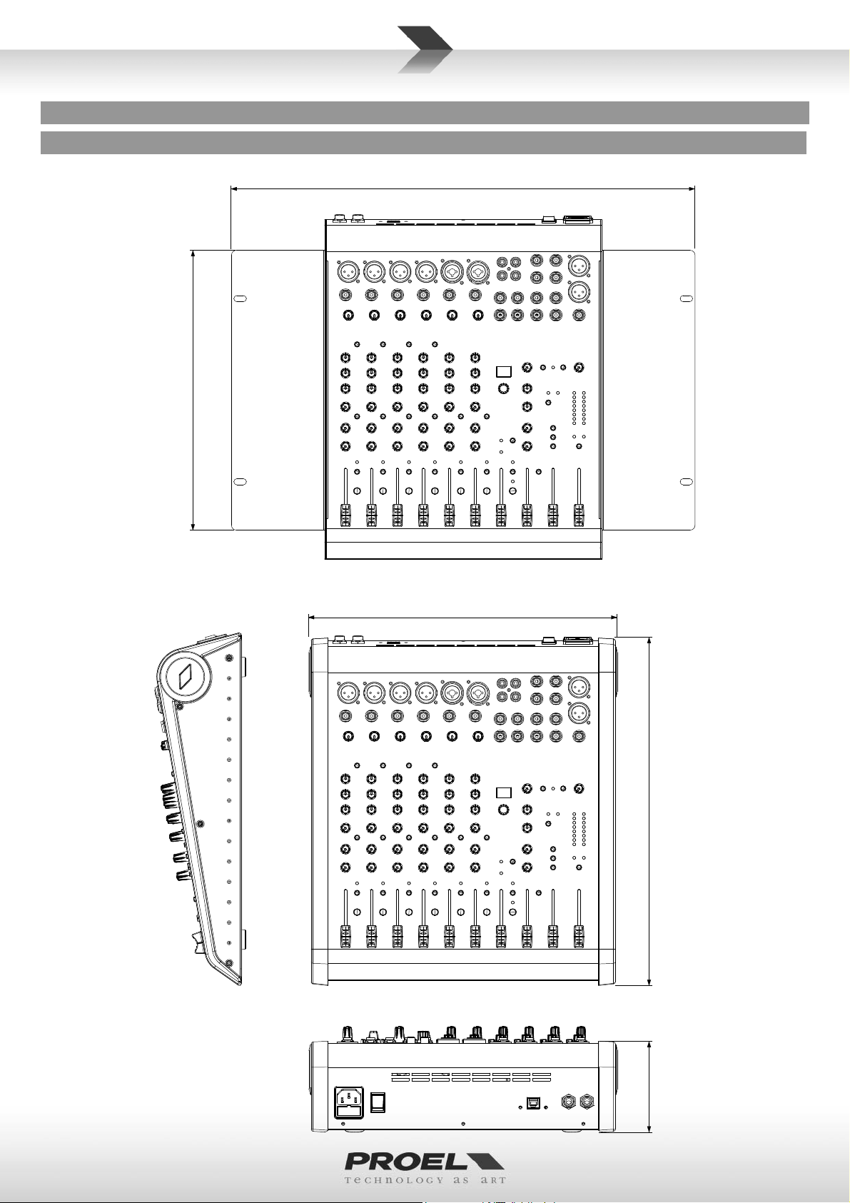
MECHANICAL DIMENSIONS
DIMENSIONI MECCANICHE
MECHANISCHE ABMESSUNGEN
DIMENSIONS MÉCANIQUES DIMENSIONES MECÁNICAS
48.3 cm
11. 5"
29.0 cm
(7U RACK)
ﺔﻳﻛﻳﻧﺎﻛﻳﻣﻟﺍ ﺩﺎﻌﺑﻷﺍ
19.0"
31.5 cm
12.4"
14.3"
36.3 cm
3.60"
9.1 cm
8
LAYOUT
LAY-OUT
LAYOUT
LAY-OUT
LAY-OUT
ﻡﻳﻣﺻﺗﻟﺍ
9
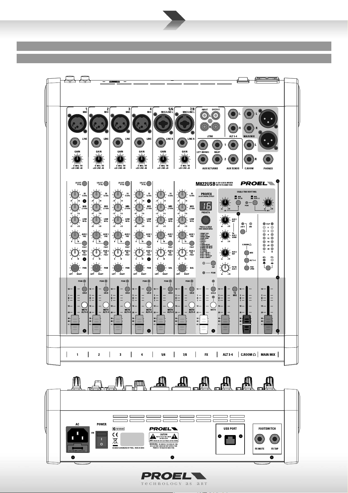
CONTROL PANEL (FIG.1)
PANNELLO DI CONTROLLO (FIG.1)
REGLER (ABB.1)
PANNEAU DE COMMANDE (FIG.1)
1
2
3
16
17
18
4
5
5
PANEL DE CONTROL (FIG.1)
36
29
32
39
45 47
34
35
37
(1 ﻝﻛﺷﻟﺍ) ﻡﻛﺣﺗﻟﺍ ﺔﺣﻭﻟ
53
54
47
40
6
7
8
9
10
11
12
13
14
6
7
8
9
10
19
12
13
14
20
21
22
23
24
30
31
33
28
46
58
57
50
51
52
38
41 42
56
49
10
15
15
25
44
55
48
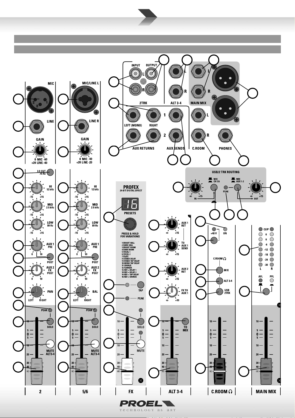
CONTROL PANEL (FIG.2)
PANNELLO DI CONTROLLO (FIG.2)
REGLER (ABB.2)
PANNEAU DE COMMANDE (FIG.2)
61
60
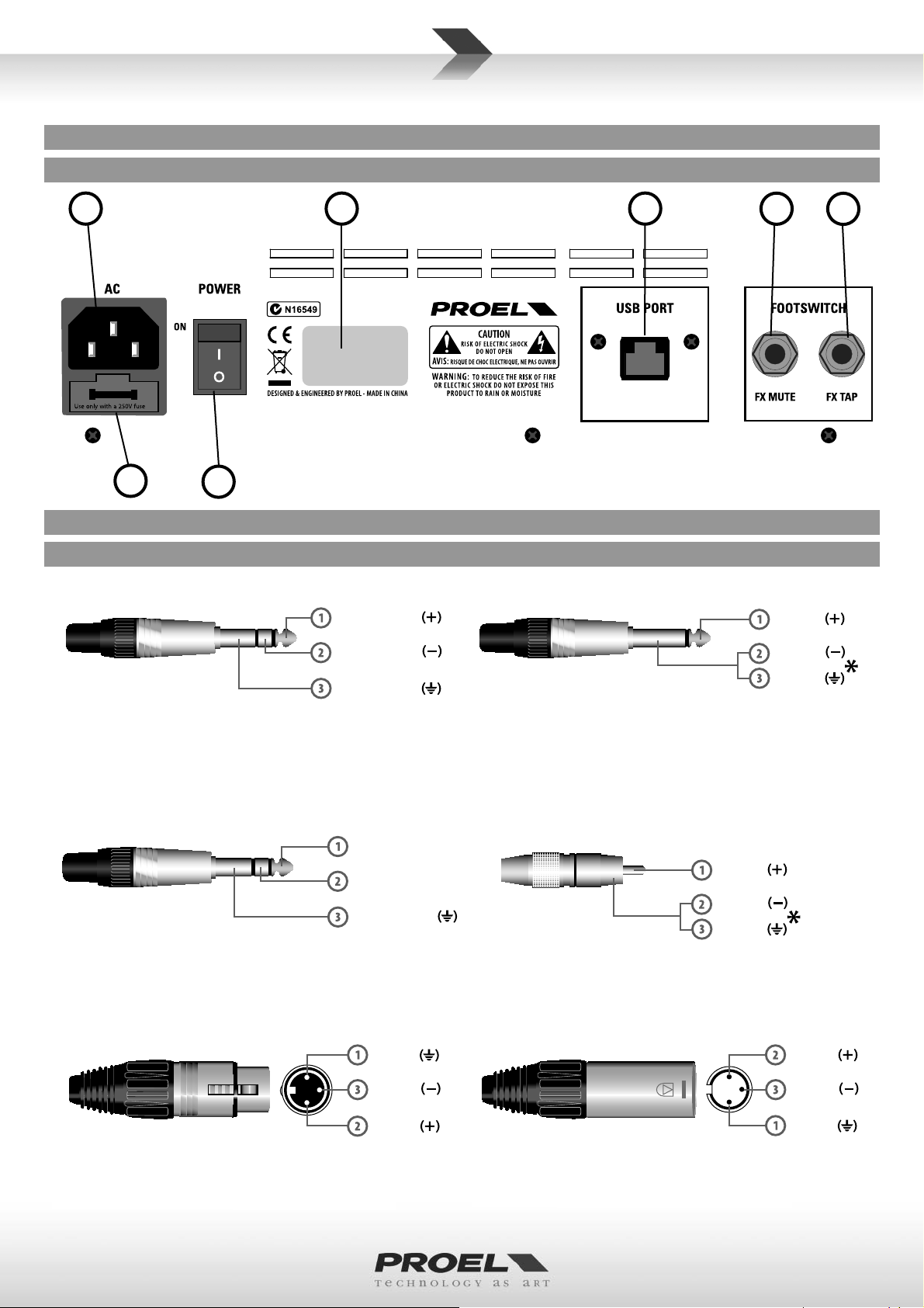
CONNECTIONS
CONNEXIONS
59
PANEL DE CONTROL (FIG.2)
62
CONNESSIONI
CONEXIONES
Ɵp - hot
(2 ﻝﻛﺷﻟﺍ) ﻡﻛﺣﺗﻟﺍ ﺔﺣﻭﻟ
43
ANSCHLÜSSE
ﺕﻼﻳﺻﻭﺗﻟﺍ
27
26
Ɵp - hot
LINE IN, various OUT
LINE IN, various OUT
Jack (balanced)
LINE IN, OUT vari
Jack (balanced)
Jack (bilanciato)
verschiedene LINE IN und OUT
Klinkenstecker (symmetrisch)
PHONES
Stereo Jack
PHONES
Jack stereo
PHONES
Stereo Jack
PHONES
Stereo-Klinkenstecker
PHONES
Jack stéréo
LINE IN, OUT divers
Jack (symétrique)
LINE IN, OUT varios
Jack (balanceado)
PHONES
Jack estéreo
ﻑﺗﺍﻭﻫ
ﻭﻳﺭﻳﺗﺳ ﺕﻭﺻ ﻝّﺻﻭﻣ
ﺓﺩﺩﻌﺗﻣ ﺝﻭﺭﺧ ﻁﺧ ،ﻝﻭﺧﺩ ﻁﺧ
LINE IN, OUT vari
(ﻥﺯﺍﻭﺗﻣ) ﺕﻭﺻ ﻝّﺻﻭﻣ
Jack (bilanciato)
PHONES
Jack stereo
ring - cold
sleeve - ground
Ɵp - leŌ
ring - right
sleeve - ground
ground
cold
LINE IN, various OUT
LINE IN, various OUT
Jack (unbalanced)
Jack (unbalanced)
*note: connect both cold and ground to
make cable from balanced to unbalanced
*note: connect both cold and ground
LINE IN, OUT vari
to make cable from balanced to unbalanced
Jack (sbilanciato)
*nota: conne ere insieme cold e ground
per cavi da bilanciato a sbilanciato
2TRK IN, OUT
TRK IN, OUT
Jack (unbalanced)
*note: connect both cold e ground to
ack (unbalanced)
make cable from balanced to unbalanced
*note: connect both cold and ground to
2TRK IN, OUT
make cable from balanced to unbalanced
Jack (sbilanciato)
*nota: conne ere insieme cold e ground
per cavi da bilanciato a sbilanciato
verschiedene LINE IN und OUT
Klinkenstecker (unsymmetrisch)
*hinweis: bei Verbindung von symmetrisch zu
unsymmetrisch Cold und Masse zusammen anschließen
LINE IN, OUT divers
Jack (asymétrique)
*note : brancher ensemble cold et ground
pour câbles de symétrique à asymétrique
2TRK IN, OUT
Klinkenstecker (unsymmetrisch)
*hinweis: bei Verbindung von symmetrisch zu
unsymmetrisch Cold und Masse zusammen anschließen
2TRK IN, OUT
Jack (asymétrique)
*note : brancher ensemble cold et ground
pour câbles de symétrique à asymétrique
cold
ground
LINE IN, OUT vari
Jack (sbilanciato)
*nota: conneƩere insieme cold e ground
per cavi da bilanciato a sbilanciato
2TRK IN, OUT
Jack (sbilanciato)
*nota: conneƩere insieme cold e ground
per cavi da bilanciato a sbilanciato
LINE IN, OUT varios
Jack (desbalanceado)
*nota: conecte juntos cold y ground para
cables de balanceado a desbalanceado
ﺓﺩﺩﻌﺗﻣ ﺝﻭﺭﺧ ﻁﺧ ،ﻝﻭﺧﺩ ﻁﺧ
(ﻥﺯﺍﻭﺗﻣﺭﻳﻏ) ﺕﻭﺻﻠّﺻﻭﻣ
ً
ﺎﻌﻣ ﻲﺿﺭﻷﺍ ﻭ ﺩﺭﺎﺑﻟﺍ ﻁﺑﺭﺍ :*!ﻪﺑﺗﻧﺍ
ﻥﺯﺍﻭﺗﻣﻟﺍ ﺭﻳﻏ ﻰﺗﺣﻭ ﻥﺯﺍﻭﺗﻣﻟﺍ ﻥﻣ ﺔﻳﺍﺩﺑ ﺕﻼﺑﺎﻛﻠﻟ
hot
cold
ground
2TRK IN, OUT
Jack (desbalanceado)
*nota: conecte juntos cold y ground para
cables de balanceado a desbalanceado
ﺝﺭﺧﻣ ،ﻝﺧﺩﻣ TRK 2
(ﻥﺯﺍﻭﺗﻣﺭﻳﻏ) ﺕﻭﺻﻠ
ً
ﺎﻌﻣ ﻲﺿﺭﻷﺍ ﻭ ﺩﺭﺎﺑﻟﺍ ﻁﺑﺭﺍ :*!ﻪﺑﺗﻧﺍ
ﻥﺯﺍﻭﺗﻣﻟﺍ ﺭﻳﻏ ﻰﺗﺣﻭ ﻥﺯﺍﻭﺗﻣﻟﺍ ﻥﻣ ﺔﻳﺍﺩﺑ ﺕﻼﺑﺎﻛﻠﻟ
hot
cold
ﺻﻭﻣ
ّ
MAIN MIX OUT
MAIN MIX OUT
Balanced female XLR
MAIN MIX OUT
Balanced female XLR
XLR bilanciato femmina
MAIN MIX OUT
XLR symmetrisch, weiblich
MAIN MIX OUT
XLR symétrique femelle
MAIN MIX OUT
MAIN MIX OUT
XLR balanceado hembra
ﻲﺳﻳﺋﺭﻟﺍ ﻲﺟﺭﺎﺧﻟﺍ ﺝﺯﻣﻟﺍ
XLR bilanciato femmina
ﻰﺛﻧﺃ ﻥﺯﺍﻭﺗﻣ XLR
hot
MIC INPUT
MIC INPUT
Balanced male XLR
MIC INPUT
Balanced male XLR
XLR bilanciato maschio
MIC INPUT
XLR symmetrisch, männlich
MIC INPUT
XLR symétrique mâle
MIC INPUT
MIC INPUT
XLR balanceado macho
ﻝﺎﺧﺩﺇ ﻥﻭﻓﻭﺭﻛﻳﻣ
XLR bilanciato maschio
ﺭﻛﺫ ﻥﺯﺍﻭﺗﻣ XLR
ground
11
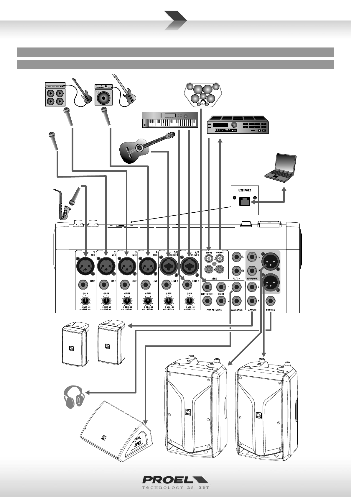
CONFIGURATION EXAMPLE
ESEMPIO DI CONFIGURAZIONE
KONFIGURATIONSBEISPIEL
EXEMPLE DE CONFIGURATION
ELECTRIC GUITAR ELECTRIC BASS
VOCAL MIC
SAX MIC
EJEMPLO DE CONFIGURACION
KEYBOARD
ACOUSTIC
GUITAR
with amplified
pickup
DRUM MACHINE
ﺔﺋﻳﻬﺗﻟﺍ ﻭﺃ ﻥﻳﻭﻛﺗﻟﺍ ﻥﻋ ﻝﺎﺛﻣ
CD / MP3 / DVD RECORDER
AND PLAYER WITH AUDIO IN/OUT
PERSONAL COMPUTER
WITH USB 2.0 PORT
12
FLASH5A desktop monitors
or other AUDIO SYSTEM
HEADPHONES
WEDGE MONITOR
or other AUDIO SYSTEM
FLASH12HDA
acƟve processed speaker
or other AUDIO SYSTEM
ENGLISH LANGUAGE
SAFETY AND PRECAUTIONS
• CAUTION: before using this product read carefully the following safety instruc ons. Take a look of this manual en rely and preserve it for
future reference.
When using any electric product, basic precau ons should always be taken, including the following:
– To reduce the risk, close supervision is necessary when the product is used near children.
– Protect the apparatus from atmospheric agents and keep it away from water, rain and high humidity places.
– This product should be site away from heat sources such as radiators, lamps and any other device that generate heat.
– Care should be taken so that objects and liquids do not go inside the product.
– The product should be connected to a power supply mains line only of the type described on the opera ng instruc ons or as marked on the
product. Connect the apparatus to a power supply using only power cord included making always sure it is in good condi ons.
–
WARNING: The mains plug is used as disconnect device, the disconnect device shall remain readily operable.
– Power supply cord should be unplugged from the outlet during strong thunderstorm or when le unused for a long period of me.
– Do not place objects on the product’s power cord or place it in a posi on where anyone could trip over, walk on or roll anything over it. Do not
allow the product to rest on or to be installed over power cords of any type. Improper installa ons of this type create the possibility of fi re hazard
and/or personal injury.
IN CASE OF FAULT
• In case of fault or maintenance this product should be inspected only by qualifi ed service personnel when:
– There is a fl aw either in the connec ons or in the supplied connec ng cables.
– Liquids have spilled inside the product.
– The product has fallen and been damaged.
– The product does not appear to operate normally or exhibits a marked change in performance.
– The product has been lost liquids or gases or the enclosure is damaged.
• Do not operate on the product, it has no user-serviceable parts inside, refer servicing to an authorized maintenance centre.
CE CONFORMITY
• Proel products comply with direc ve 2004/108/EC (EMC), as stated in EN 55013 standard and with direc ve 2006/95/CE (LVD), as stated in EN
60065 standard.
• Under the EM disturbance, the ra o of signal-noise will be changed above 10dB.
PACKAGING, SHIPPING AND COMPLAINT
• This unit package has been submi ed to ISTA 1A integrity tests. We suggest you control the unit condi ons immediately a er unpacking it.
• If any damage is found, immediately advise the dealer. Keep all unit packaging parts to allow inspec on.
• Proel is not responsible for any damage that occurs during shipment.
• Products are sold “delivered ex warehouse” and shipment is at charge and risk of the buyer.
• Possible damages to unit should be immediately no fi ed to forwarder. Each complaint for package tampered with should be done within eight
days from product receipt.
WARRANTY AND PRODUCTS RETURN
• Proel products have opera ng warranty and comply their specifi ca ons, as stated by manufacturer.
• Proel warrants all materials, workmanship and proper opera on of this product for a period of two years from the original date of purchase. If
any defects are found in the materials or workmanship or if the product fails to func on properly during the applicable warranty period, the owner
should inform about these defects the dealer or the distributor, providing receipt or invoice of date of purchase and defect detailed descrip on.
This warranty does not extend to damage resul ng from improper installa on, misuse, neglect or abuse. Proel S.p.A. will verify damage on returned
units, and when the unit has been properly used and warranty is s ll valid, then the unit will be replaced or repaired. Proel S.p.A. is not responsible
for any "direct damage" or "indirect damage" caused by product defec veness.
INSTALLATION AND DISCLAIMER
• Proel products have been expressly designed for audio applica on, with signals in audio range (20Hz to 20kHz). Proel has no liability for damages
caused in case of lack of maintenance, modifi ca ons, improper use or improper installa on non-applying safety instruc ons.
• Proel S.p.A. reserves the right to change these specifi ca ons at any me without no ce.
• Proel S.p.A. declines any liability for damages to objects or persons caused by lacks of maintenance, improper use, installa on not performed
with safety precau ons and at the state of the art.
POWER SUPPLY AND MAINTENANCE
• Clean only with dry cloth.
• Before connec ng the product to the mains outlet make certain that the mains line voltage matches that shown on the rear of the product, a
tolerance of up to ±10% is acceptable.
• CHECK THE CONDITION OF THE PROTECTION FUSE, ACCESSIBLE OUTWARD, ONLY WITH THE APPARATUS SWITCHED OFF AND
DISCONNECTED FROM THE MAINS LINE OUTLET.
• REPLACE THE PROTECTION FUSE ONLY WITH SAME TYPE AS SHOWN ON THE PRODUCT.
• IF AFTER THE SUBSTITUTION, THE FUSE INTERRUPTS AGAIN THE APPARATUS WORKING, DO NOT TRY AGAIN THEN CONTACT THE
PROEL SERVICE CENTER.
13

GENERAL INFORMATION
Thank you for having chosen a PROEL product.
The new models in the M Series have been updated with new and improved features, repacked into a new stylish
package. While keeping the superior audio quality, the full set of features and the highest number of MIC inputs in the
category that have been the hallmarks of the previous M Series, the M models feature the new PROEL 24bit PROFEX
DSP, one of the fi nest digital eff ect of its class, providing 256 studio-grade algorithms (including mono and stereo TAP
DELAY) and a convenient 2 digit LED display.
Designed and engineered in Italy by PROEL, M mixers are hosted in an ultra-rugged stylish metal case with ABS sides,
providing extended durability for a stage-proof use. As in the previous series, all the models include both a padded
carrying bag and metal brackets for 19” rack moun ng.
The 8-in, 6-mic M822USB now includes a versa le USB rou ng sec on, for a complete control of the signals to and from
the PC and a built-in universal power supply.
OPERATING INSTRUCTIONS (FIG. 1 / 2)
1. MIC Input
This is a female XLR connector, which accepts a balanced microphone input from almost any type of microphone. The
XLR inputs are wire as follows:
Pin 1 = shield or ground
Pin 2 = + posi ve or “hot”
Pin 3 = - nega ve or “cold”
2. LINE Input
This is a ¼” (6.3mm) jack connector, which accepts a balanced or unbalanced line level input signal from almost any
source. When connec ng a balanced signal, wire them as follows:
Tip = + posi ve or “hot”
Ring = - nega ve or “cold”
Sleeve = shield or ground
When connec ng an unbalanced signal, wire them as follows:
Tip = + posi ve or “hot”
Sleeve = shield or ground
3. MONO CHANNEL GAIN Control
The gain control adjusts the input sensi vity of the mic and line inputs. This allows the signal from mics and instruments
to be adjusted to op mal internal levels. If the signals are plugged into the XLR input there is a 0 dB of gain with the
knob turned all way down, rising up to 60 dB of gain fully up. When connected to the jack input of any channels, there
is 20 dB of a enua on all way down and 40 dB of gain fully up, with a unity gain (0 dB) if centered.
4. LO CUT switch
This switch cuts bass frequencies below 75 Hz at a rate of 18 dB per octave. We recommend that you use the LO CUT
fi lter on every microphone applica on except kick drum, bass guitar, bassy synth patches, or recordings. These aside,
there isn’t much down there that you want to hear, and fi ltering it out makes the low stuff you do want much more
crisp and tasty. Not only that, but the LO CUT fi lter can help reduce the possibility of feedback in live situa ons and
it helps to conserve the amplifi er power. Another way to use the LO CUT fi lter is in combina on with the LOW EQ on
vocals during live performances. Many mes, bass shelving EQ can really benefi t voices. Trouble is, adding LOW EQ also
boosts stage rumble, mic handling clunks, and breath pops. LO CUT removes all those problems so you can add LOW
EQ without losing a woofer.
5. EQ sec on HIGH control
This control gives you up to 15dB boost or cut at 12KHz with a “SHELVING” curve shape. Use it to increase or reduce
the sound “clarity” or “brightness”.
6. EQ sec on MID control
This control gives you up to 15 dB boost or cut at 2.5 KHz with a “PEAKING” curve shape. Use it to add or reduce the
sound “presence”.
7. EQ sec on LOW control
This control gives you up to 15dB boost or cut at 80Hz with a “SHELVING” curve shape. Use it to increase or reduce the
sound “punch”.
8. AUX 1 control (pre/post)
This control sends the signal to the AUX 1 output. This signal is normally pre-fader, but it could be set post-fader pressing
the POST switch: in this case the signal level depends on the posi on of the channel FADER.
14

9. POST switch
Push this switch to set the AUX 1 control post-fader or release it to set the AUX 1 pre-fader. The pre-fader se ng is
preferable if you want to use the AUX 1 send as stage monitor, in order to have your stage mix independent from MAIN
MIX.
10. AUX 2 control (send to FX post)
This control sends the signal to the AUX 2 output and to the internal DIGITAL EFFECT PROCESSOR. This signal is postfader, in other words it depends on the posi on of the channel FADER.
11. PAN control
It adjusts the amount of channel signal sent to the le versus the right outputs. Use it to posi on the sound origin in a
panoramic stereo scene.
12. PEAK detector and SOLO ac ve
This LED has two func ons:
If the PEAK LED lights permanently this means that you have ac vated the SOLO switch of this channel.
If the PEAK LED fl ashes this means that the input signal is near to the CLIPPING point.
IMPORTANT: if the LED PEAK fl ashes reduce the level of the input signal using the GAIN control.
13. SOLO switch
This switch allows you to hear signals through your headphones or control room outputs and to display the level on LED
meters. Use the SOLO in live sets to pre-listen channels before they are fed into the mix or just to check out a par cular
channel any me during a session. You can solo as many channels at a me as you like.
IMPORTANT: The solo signal is pre-fader if SOLO MODE is in PFL posi on, so what you check is the signal entering the
channel. The solo signal is post-fader if SOLO MODE is in AFL posi on, so what you check is the signal sent from the
channel fader to the MAIN MIX.
14. MUTE/ALT 3-4 switch
The dual-purpose MUTE/ALT 3-4 switch serves two func ons: mu ng and as an extra stereo bus:
If you want to mute the channel switch this bu on, disengage the ALT 3-4 (51) switch and TO MIX (46) switch and don’t
use the ALT 3-4 outputs.
If you want to create an alternate mix switch this bu on to assign the channels to the ALT 3-4 mix, connect the ALT3-
4 outputs (45) to whatever des na on you desire, the ALT3-4 fader (44) will control the level of your alternate mix,
engaging the ALT 3-4 switch (51), the signals will appear also at the CONTROL ROOM and PHONES outputs.
If you want to create a subgroup with several channels (when doing live sound or mixdown, it’s o en handy to control
the level of several channels with one knob), switch this bu on to simply assigning these channels to the ALT 3-4 mix
and engaging the TO MIX switch (46), the ALT3-4 fader (44) will control the level of your sub-group.
15. FADER LEVEL control
It adjusts the level of the channel signal and sends it to the MAIN MIX and to the CTRL ROOM/PHONES outputs.
16. MIC LINE L MONO Input
This is a female JACK/XLR combo connector that accepts a balanced microphone XLR input from almost any type of
microphone, or a line JACK input that accepts a balanced or unbalanced line level input signal from almost any line
source. If the LINE R jack is not inserted, this channel operates like a MONO channel with this input as a single signal
source. Wiring is the same of previous paragraphs.
17. LINE R Input
This is a ¼” (6.3mm) jack connector, which accepts a balanced or unbalanced line level input signal from almost any line
source. This is used only in presence of LINE L jack input to use the channel as STEREO.
18. STEREO CHANNEL GAIN Control
The gain control adjusts the input sensi vity of the mic and line inputs. This allows the signal from mics and instruments
to be adjusted to op mal internal levels. If the signals are plugged into the XLR input there is a 0 dB of gain with the
knob turned all way down, rising up to 40 dB of gain fully up. When connected to the jack input of any channels, there
is 20 dB of a enua on all way down and 20 dB of gain fully up, with a unity gain (0 dB) if centered.
19. BAL control
It adjusts the amount of channel signal sent to the le versus the right outputs if the channel is used as MONO, or it
fades the LEFT or RIGHT signal amount if the channel is used as STEREO.
20. PRESETS selector and display
The internal PROFEX digital eff ect processor is built around a powerful DSP and 24bit AD/DA converters. It includes 16
di
ff erent presets of studio-grade eff ect algorithm, each one featuring 16 diff erent varia ons of the internal parameters,
for a total of 256 eff ects available.
15

HOW TO USE THE PROFEX EFFECT:
- rotate the SELECTOR knob to choose the type of eff ect (preset) you want to use;
- to select a varia on of the preset, press and hold the knob un l the display fl ashes;
- rotate the knob and choose one of the 16 varia ons available;
- press and hold again the knob un l the display stops fl ashing to confi rm the selec on and to return back to the
preset selec on;
- send the signal to the eff ect with the AUX control (10) of the channel you want to add the eff ect to;
- rotate the FX LEVEL (25) knob un l you hear the eff ect added to the original signal;
- adjust the AUX controls (10) just before the signal input clipping indicated by the peak led (22);
- re-adjust the FX LEVEL (25) knob to combine the wet eff ected signal with the natural dry signal.
NOTE: the preset and the varia on selected in the PROFEX eff ect are kept in the memory even if you turn off the
mixer.
PRESET DESCRIPTION:
p 1. BRIGHT HALL - This type of reverb simulates the ambience of a grand concert hall. Dense, smooth reverb with
long pre delay and a lot of high frequency refl ec ons. Works well with vocals, electric and acous c guitars, strings.
The VARIATIONS vary the decay me and the hall size from bigger [1] to smallest [16].
p 2. DARK HALL - This type of reverb simulates the ambience of a grand concert hall. Dense, smooth reverb with long
pre delay and a few of high frequency refl ec ons. Works well with vocals, guitars, woodwinds.
The VARIATIONS vary the decay me and the hall size from bigger [1] to smallest [16].
p 3. BRIGHT ROOM - This type of reverb reproduces the more in mate ambience of natural room acous cs. Feature
a lot of early refl ec ons with a lot of high frequency. Works well with vocals, woodwinds, strings, drums.
The VARIATIONS vary the decay me and the room size from bigger [1] to smallest [16].
p 4. DARK ROOM - This type of reverb reproduces the more in mate ambience of natural room acous cs. Feature a
lot lot of early refl ec ons with a few of high frequency. Works well with vocals, fi ngered guitars, drums.
The VARIATIONS vary the decay me and the room size from bigger [1] to smallest [16].
p 5. VOCAL 1 (STAGE REVERB) - Amazing reverb designed for vocals with a long tail.
The VARIATIONS vary the decay me from long tail [1] to short tail [16], alterna ng plate, spring or hall types of
reverb.
p 6. VOCAL 2 (CLUB REVERB) - Amazing reverb designed for vocals with a dense tail.
The VARIATIONS vary the decay me from long tail [1] to short tail [16], alterna ng tape, hall or spring types of
reverb.
p 7. PLATE - This is a simula on of metal plate reverb, as used on classic recordings from the ‘70s and ‘80s.
The VARIATIONS vary the decay me from long tail [1] to short tail [16].
p 8. STEREO DELAY - Echo eff ect with ping-pong of le and right channels.
The VARIATIONS vary from long delay mes [1] to short delay mes [16].
p 9. STEREO TAP DELAY - Like STEREO DELAY above with me set by the user TAP bu on (22) just below.
The VARIATIONS vary from 5% [1] to 90% [16] of feedback quan ty.
p 10. MONO TAP DELAY - Typical mono delay with me set by the user TAP bu on (22) just below.
The VARIATIONS vary from 0% [1] to 75% [16] of feedback quan ty.
p 11. CHORUS - Typical modula on eff ect, provides a so , ethereal sweeping eff ect. Perfect for enhancement of
electric and acous c guitar and bass. Also adds a drama c eff ect to vocals, par cularly group harmonies and choirs.
The VARIATIONS increase the modula on frequency from 0.5Hz [1] to 5Hz [16].
p 12. FLANGER - Typical modula on eff ect, creates a strong sweeping eff ect, par cularly eff ec ve on rock electric
guitar, lead and rhythm.
The VARIATIONS increases the modula on frequency from 0.2Hz [1] to 3Hz [16].
p 13. REVERB+DELAY 1 - Typical vocal hall reverb and stereo delay combined together.
The VARIATIONS vary from long tail [1] to short tail [16].
p 14. REVERB+DELAY 2 - Typical vocal hall reverb and mono delay combined together.
The VARIATIONS vary from long tail [1] to short tail [16].
p 15. REVERB+TAP DELAY - Typical vocal hall reverb and mono TAP delay combined together.
The mono delay me is set by the user TAP bu on (22) just below.
The VARIATIONS vary from long tail [1] to short tail [16] and from 0% to 75% of feedback quan ty [1-16].
p 16. REV+CHORUS - Typical vocal reverb and chorus eff ect combined together.
The VARIATIONS vary from long tail [1] to short tail [16] and increases the modula on frequency from 0.5Hz to 5Hz
[1-16].
21. TAP bu on and LED
When “TAP DELAY” eff ects (p 9, 10, 15) are selected, by pushing at least two mes this bu on it’s possible to set the
desired delay me, according to music rhythm. The TAP LED fl ashes in sync with the delay me set.
16

22. PEAK detector
If the peak LED fl ashes this means that the signal is too high, near to the clipping of the eff ect input stage. In this case,
reduce the level of the AUX / FX sends.
23. FX SOLO switch and LED
This switch allows you to hear the signals of FX send (PFL) or FX return (AFL) through your headphones or control room
outputs and to display the level on LED meters.
24. MUTE bu on
Engage this switch if you want to mute the signal from the internal eff ect.
NOTE: the eff ect can be turned on/off also by means of a footswitch connected to the FX MUTE jack socket.
25. FX LEVEL control
It adjusts the level of the internal eff ect signal sent to the MAIN MIX outputs.
26. FX TAP jack input
¼” (6.3mm) unbalanced (TS) jack for temporary, normally open footswitch (not supplied - suggested footswitch is the
PROEL model GF29). When “TAP DELAY” eff ects (p 9, 10, 15) are selected, by pressing at least two mes the footswitch
it’s possible to set the desired delay me, according to music rhythm.
27. FX MUTE jack input
You can connect a footswitch to MUTE the mixer internal eff ect (suggested footswitch is PROEL model GF29).
28. FX TO AUX1 level control
It adjusts the level of the internal eff ect signal sent to the AUX 1 output.
29. AUX RET 1 jack input
Unbalanced jack connectors of the auxiliary stereo input (note: the L input can be used as MONO if R input is le
unconnected). This input can be used for the return signal from outboard eff ects or for connec ng any instrument or
equipment with a line output.
30. AUX RET 1 level control
It adjusts the level of the AUX RET 1 inputs and send it to the MAIN MIX and to the CTRL ROOM/PHONES outputs on
master sec on.
31. TO AUX 1 SEND level control
It adjusts the level of the AUX RET 1 inputs and send it to the AUX 1 output.
32. AUX RET 2 jack input
Unbalanced jack connectors of the auxiliary stereo input (note: the L input can be used as MONO if R input is le
unconnected). This input can be used for the return signal from outboard eff ects or for connec ng any instrument or
equipment with a line output.
33. AUX RET 2 level control
It adjusts the level of the AUX RET 1 inputs and send it to the MAIN MIX and to the CTRL ROOM/PHONES outputs on
master sec on.
34. AUX SEND 1 jack output
This jack connector sends out unbalanced line-level signals made of the sum of the input channel’s AUX 1 sends, usually
for connec ng to the inputs of an external eff ect devices or stage monitor amplifi ers.
35. AUX SEND 2 jack output
This jack connector sends out unbalanced line-level signals made of the sum of the input channel’s AUX 2 sends, usually
for connec ng to the inputs of an external eff ect devices or stage monitor amplifi ers. This signal is post-fader, or in other
words it depends on the posi on of the channel’s FADER.
36. 2TRK inputs
Use these unbalanced RCA connectors to patch the output of a player, such as an analog tape deck, MP3 player, CD/DVD
player or a Personal Computer.
37. USB/2TRK IN level control
It adjusts the level of the 2TRK INPUT and USB input (audio signal from PC).
38. MIX - CH7/8 switch
This switch routes the 2TRK IN or USB input signal directly to MAIN MIX outputs or to the channel 7/8. Rou ng the signal
to channel 7/8, you can use all features of the stereo channel before sending the signal to the MAIN MIX: equaliza
aux sends and the internal eff ect processor.
39. 2TRK outputs
Use these unbalanced RCA connectors to send out the MAIN MIX or AUX 1/2 signals to a recorder, such as an analog
on,
17
 Loading...