


USER’S MANUAL
ENGLISH
www.proel.com

2

Index |
|
FCC COMPLIANCE NOTICE. . . . . . . . . . . . . . . . . . . . |
. 4 |
WARNING . . . . . . . . . . . . . . . . . . . . . . . . . . . . . . . . . . |
.4 |
SAFETY AND PRECAUTIONS . . . . . . . . . . . . . . . . . . |
. 6 |
IN CASE OF FAULT . . . . . . . . . . . . . . . . . . . . . . . . . . . |
. 6 |
TROUBLESHOOTING . . . . . . . . . . . . . . . . . . . . . . . . . |
. 6 |
CE CONFORMITY. . . . . . . . . . . . . . . . . . . . . . . . . . . . . |
6 |
PACKAGING, SHIPPING AND COMPLAINT . . . . . . |
. 7 |
WARRANTY AND PRODUCTS RETURN.. . . . . . . . . . |
7 |
INSTALLATION AND DISCLAIMER. . . . . . . . . . . . . . |
7 |
POWER SUPPLY AND MAINTENANCE. . . . . . . . . . |
. 7 |
OVERVIEW. . . . . . . . . . . . . . . . . . . . . . . . . . . . . . . . . . |
9 |
INTRODUCTION . . . . . . . . . . . . . . . . . . . . . . . . . . . . . |
10 |
CONTROLS AND CONNECTIONS. . . . . . . . . . . . . . . |
10 |
FRONT PANEL. . . . . . . . . . . . . . . . . . . . . . . . . . . . |
10 |
1.. USB port.. . . . . . . . . . . . . . . . . . . . . . . . . . . . . . |
10 |
2.. Display . . . . . . . . . . . . . . . . . . . . . . . . . . . . . . . . |
10 |
3.. Preset buttons.. . . . . . . . . . . . . . . . . . . . . . . . . |
10 |
4.. DATA entry knob. . . . . . . . . . . . . . . . . . . . . . . . |
10 |
5.. PG UP - PG DW buttons. . . . . . . . . . . . . . . . . . |
10 |
6.. ESC button. . . . . . . . . . . . . . . . . . . . . . . . . . . . . |
11 |
7.. Processing menu buttons . . . . . . . . . . . . . . . . |
11 |
8.. Input meters. . . . . . . . . . . . . . . . . . . . . . . . . . . |
11 |
9.. A - B input MUTE buttons. . . . . . . . . . . . . . . . |
11 |
10.. A - B input EDIT buttons. . . . . . . . . . . . . . . . |
11 |
11.. Output meters . . . . . . . . . . . . . . . . . . . . . . . . . |
11 |
12.. Output MUTE buttons. . . . . . . . . . . . . . . . . . . |
11 |
13.. Output EDIT buttons. . . . . . . . . . . . . . . . . . . . |
11 |
14.. RTA MIC input . . . . . . . . . . . . . . . . . . . . . . . . . |
12 |
REAR PANEL . . . . . . . . . . . . . . . . . . . . . . . . . . . . . |
12 |
15.. AC ~. . . . . . . . . . . . . . . . . . . . . . . . . . . . . . . . . |
12 |
16.. FUSE holder. . . . . . . . . . . . . . . . . . . . . . . . . . . |
12 |
17.. POWER switch. . . . . . . . . . . . . . . . . . . . . . . . |
12 |
18.. AES/EBU Digital Input. . . . . . . . . . . . . . . . . . |
12 |
19.. TERMINATE switch. . . . . . . . . . . . . . . . . . . . |
12 |
20.. PRONET Network OUT connector. . . . . . . . |
12 |
21.. PRONET Network IN connector. . . . . . . . . . |
12 |
22.. Balanced XLR Output connectors. . . . . . . . |
12 |
23.. Balanced XLR Input connectors.. . . . . . . . . |
12 |
24.. Balanced XLR Thru connectors . . . . . . . . . . |
12 |
25.. – 6dB PAD switch. . . . . . . . . . . . . . . . . . . . . . |
12 |
26.. GND LIFT switch. . . . . . . . . . . . . . . . . . . . . . . |
12 |
CABLE CONNECTIONS. . . . . . . . . . . . . . . . . . . . . . . |
13 |
Audio Cables. . . . . . . . . . . . . . . . . . . . . . . . . . . . . |
13 |
Balanced Input / Output Connections |
|
(Recommended) . . . . . . . . . . . . . . . . . . . . . . . . . . |
13 |
Un-balanced Input / Output Connections (Not |
|
recommended) . . . . . . . . . . . . . . . . . . . . . . . . . . . |
13 |
Digital Input AES/EBU Connection. . . . . . . . . . . |
13 |
USB Cable . . . . . . . . . . . . . . . . . . . . . . . . . . . . . . . |
13 |
PRONET Cable.. . . . . . . . . . . . . . . . . . . . . . . . . . . |
13 |
OPERATING MODE.. . . . . . . . . . . . . . . . . . . . . . . . . . |
14 |
REMOTE MODE using PRONET software. . . . . |
14 |
RUN TIME MODE. . . . . . . . . . . . . . . . . . . . . . . . . |
14 |
PRESETS . . . . . . . . . . . . . . . . . . . . . . . . . . . . . . . . . . . |
14 |
DEAFAULT Presets . . . . . . . . . . . . . . . . . . . . . . . . |
14 |
FACTORY Presets . . . . . . . . . . . . . . . . . . . . . . . . . |
14 |
PROTECTED Presets.. . . . . . . . . . . . . . . . . . . . . . |
14 |
USER Presets. . . . . . . . . . . . . . . . . . . . . . . . . . . . |
14 |
Recall a Preset. . . . . . . . . . . . . . . . . . . . . . . . . . . . . . |
15 |
Save a Preset . . . . . . . . . . . . . . . . . . . . . . . . . . . . . . . |
15 |
Delete a Preset.. . . . . . . . . . . . . . . . . . . . . . . . . . . . . |
15 |
SETUP. . . . . . . . . . . . . . . . . . . . . . . . . . . . . . . . . . . . . |
16 |
MISCELLANEOUS. . . . . . . . . . . . . . . . . . . . . . . . . |
16 |
TIME. . . . . . . . . . . . . . . . . . . . . . . . . . . . . . . . . . . . |
16 |
GANGING.. . . . . . . . . . . . . . . . . . . . . . . . . . . . . . . |
16 |
DEVICE NAME.. . . . . . . . . . . . . . . . . . . . . . . . . . . |
16 |
CHANNEL NAME. . . . . . . . . . . . . . . . . . . . . . . . . |
16 |
FIRMWARE UPDATE.. . . . . . . . . . . . . . . . . . . . . . |
17 |
LOCK. . . . . . . . . . . . . . . . . . . . . . . . . . . . . . . . . . . . |
17 |
PROCESSING MENU . . . . . . . . . . . . . . . . . . . . . . . . . |
18 |
EDITING processing menu parameters. . . . . . . . . |
18 |
ROUTING - signal routing. . . . . . . . . . . . . . . . . . |
18 |
LEVEL - levels and phase polarity. . . . . . . . . . . |
18 |
XOVER - crossover filters. . . . . . . . . . . . . . . . . . |
18 |
DELAY. . . . . . . . . . . . . . . . . . . . . . . . . . . . . . . . . . . |
19 |
GEQ - graphic equalizer.. . . . . . . . . . . . . . . . . . . |
20 |
PEQ - parametric equalizer. . . . . . . . . . . . . . . . . |
21 |
DEQ - dynamic equalizer . . . . . . . . . . . . . . . . . . . |
23 |
DYN - dynamic processor . . . . . . . . . . . . . . . . . . |
25 |
SPL MANAGEMENT. . . . . . . . . . . . . . . . . . . . . . . . . |
27 |
RTA. . . . . . . . . . . . . . . . . . . . . . . . . . . . . . . . . . . . . . . . |
28 |
TYPICAL CONFIGURATIONS. . . . . . . . . . . . . . . . . . . |
29 |
PC260 2 x 3 xover |
|
(advanced live or disco system).. . . . . . . . . . . . |
29 |
PC260 2 x 2 xover + 1 zone |
|
(advanced live or disco pub system). . . . . . . . . |
29 |
PRONET NETWORK . . . . . . . . . . . . . . . . . . . . . . . . . . |
30 |
The PRONET philosophy. . . . . . . . . . . . . . . . . . . |
30 |
Connecting devices . . . . . . . . . . . . . . . . . . . . . . . |
30 |
Connecting devices to a PRONET NETWORK.. |
30 |
Assign the ID number.. . . . . . . . . . . . . . . . . . . . . |
31 |
Working with PRONET. . . . . . . . . . . . . . . . . . . . . |
31 |
USB2CAN converter.. . . . . . . . . . . . . . . . . . . . . . |
32 |
CLOCK BATTERY REPLACEMENT.. . . . . . . . . . . . . . |
33 |
TECHNICAL SPECIFICATION.. . . . . . . . . . . . . . . . . . |
34 |
Appendix A (signal to power). . . . . . . . . . . . . . . . . . |
35 |
3

FCC COMPLIANCE NOTICE
This is a class A digital device, which is marked for use in a commercial, industrial or business environment, exclusive of used by the general public or used in the home..
This device complies with Part 15 of the FCC Rules.. Operation is subject to the following two conditions:
(1)this device may not cause harmful interference, and
(2)this device must accept any interference received, including interference that may cause undesired operation..
CAUTION: Changes or modications to this product not expressly approved by the manufacturer could void the user's authority to operate this product.
NOTE: This equipment has been tested and found to comply with the limits for a Class A digital device, pursuant to Part 15 of FCC Rules.. These limits are designed to provide reasonable protection against harmful interference when the equipment is operated in a commercial environment.. This equipment generates, uses and can radiate radio frequency energy and, if not installed and used in accordance with the instruction manual, may cause harmful interference to radio communications.. Operations of this equipment in a residential area is likely to cause harmful interference in which case the user will be required to correct the interference at his own expense..
WARNING
This is a class A product. In a domestic environment this product may cause radio interference in which case the user may be required to take adequate measure.
Under the EM disturbance, the ratio of signal-noise will be changed above 10dB..
4

This marking shown on the product or its literature, indicates that it should not be disposed with other household wastes at the end of its working life.. To prevent possible harm to the enviroment or human health from uncontrolled waste disposal, please separate this from other types of wastes and recycle it responsibly to promote the sustainable reuse of material resources.. Household users should contact either the retailer where they purchased this product, or their local government office, for details of where and how they can take this item for environmentally safe recycling.. Business users should contact their supplier and check the terms and conditions of the purchase contract.. This product should not be mixed with other commercial wastes for disposal..
The lightning flash with arrowhead symbol within an equilateral triangle is intended to alert the user to the presence of uninsulated “dangerous voltage” within the product’s enclosure, that may be of sufficient magnitude to constitute a risk of electric shock to persons..
The exclamation point within an equilateral triangle is intended to alert the user to the presence of important operating and maintenance (servicing) instructions in the literature accompanying the appliance..
The information contained in this publication has been carefully prepared and checked.. However no responsibility will be taken for any errors.. All rights are reserved and this document cannot be copied, photocopied or reproduced in part or completely without written consent being obtained in advance from PROEL.. PROEL reserves the right to make any aesthetic, functional or design modification to any of its products without any prior notice.. PROEL assumes no responsibility for the use or application of the products or circuits described herein..
5
SAFETY AND PRECAUTIONS
•  CAUTION: Before using this product read carefully the following safety instructions.. Take a look of this manual entirely and preserve it for future reference..
When using any electric product, basic precautions should always be taken, including the following:
– To reduce the risk, close supervision is necessary when the product is used near children..
– Protect the apparatus from atmospheric agents and keep it away from water, rain and high humidity places..
– This product should be site away from heat sources such as radiators, lamps and any other device that generate heat..
– This product should be located so that its location or position does not interfere with its proper ventilation and heating dissipation..
– Care should be taken so that objects and liquids do not go inside the product..
– The product should be connected to a power supply mains line only of the type described on the operating instructions or as marked on the product.. Connect the apparatus to a power supply using only power cord included making always sure it is in good conditions..
–  WARNING: The mains plug is used as disconnect device, the disconnect device shall remain readily operable..
– Do not cancel the safety feature assured by means of a polarized line plug (one blade wider than the other) or with a earth connection..
– Make sure that power supply mains line has a proper earth connection..
– Power supply cord should be unplugged from the outlet during strong thunderstorm or when left unused for a long period of time..
– Do not place objects on the product’s power cord or place it in a position where anyone could trip over, walk on or roll anything over it.. Do not allow the product to rest on or to be installed over power cords of any type.. Improper installations of this type create the possibility of fire hazard and/or personal injury..
– This product in combination with loudspeakers may be capable of producing |
Duration Per Day |
Sound Level dBA |
Typical |
|
sound levels that could cause permanent hearing loss.. Exposure to extremely |
In Hours |
Slow Response |
Example |
|
8 |
90 |
Duo in small club |
||
high noise levels may cause permanent hearing loss. . Individuals vary |
||||
|
|
|
||
considerably in susceptibility to noise-induced hearing loss, but nearly everyone |
6 |
92 |
|
|
will lose some hearing if exposed to sufficiently intense noise for a period of time.. |
|
|
|
|
4 |
95 |
Subway Train |
||
The U..S.. Government’s Occupational Safety and Health Administration (OSHA) |
|
|
|
|
3 |
97 |
|
||
has specified the permissible noise level exposures shown in the following chart.. |
|
|||
|
|
|
||
2 |
100 |
Very loud classical music |
||
According to OSHA, any exposure in excess of these permissible limits could |
||||
|
|
|
||
result in some hearing loss.. To ensure against potentially dangerous exposure |
1..5 |
102 |
|
|
to high sound pressure levels, it is recommended that all persons exposed |
|
|
|
|
1 |
105 |
Traffic noise |
||
to equipment capable of producing high sound pressure levels use hearing |
|
|
|
|
0..5 |
110 |
|
||
protectors while the equipment is in operation.. Ear plugs or protectors in the ear |
|
|||
|
|
|
||
0..25 or less |
115 |
Loudest parts at a rock concert |
||
canals or over the ears must be worn when operating the equipment in order to |
||||
|
|
|
||
prevent permanent hearing loss if exposure is in excess of the limits set forth |
|
|
|
|
here.. Keep your's attention that childrens and pets are more suscetible to excessive noise levels.. |
|
|
||
IN CASE OF FAULT
•In case of fault or maintenance this product should be inspected only by qualified service personnel when:
– There is a flaw either in the connections or in the supplied connecting cables..
– Liquids have spilled inside the product..
– The product has fallen and been damaged..
– The product does not appear to operate normally or exhibits a marked change in performance..
– The product has been losted liquids or gases or the enclosure is damaged..
•Do not operate on the product, it has no user-serviceable parts inside, refer servicing to an authorized maintenance centre.
TROUBLESHOOTING
No Power |
• The device's "POWER" switch is off. |
|
• Make sure the mains AC outlet is live (check if LED PWR lights up). |
|
• Make sure the mains plug is securely plugged into mains AC outlet. |
No Sound |
• Is the MUTE buttons dis-engaded? |
|
• Is the INPUT METER LED illuminated? If not check if your signal level is too low or check the signal cable, mixer and |
|
other equipment setting and cabling.. |
|
• Are you sure your signal cables works properly? check it using a cable tester or replacing with a new one. |
Distorted Sound |
• Input signal level is too high. Engage the -6dB PAD button on rear panel and/or turn down your level controls.. |
|
|
Different channel |
• Check if are using a balanced cable for one channel and an unbalanced one for the other, as this would cause a |
level |
considerable difference in channel levels.. |
Noise / Hum |
• Enable GND LIFT button on rear panel. |
|
• Whenever possible, preferably use only balanced cables. Unbalanced lines may also be used but may result in noise |
|
over long cable runs.. |
|
• Sometimes it helps to plug all audio equipment into the same AC circuit so they share a common ground. |
CE CONFORMITY
• Proel PC260 complies with directive 2004/108/EC (EMC), as stated in EN 55103-1 and EN 55103-2 standards and with directive 2006/95/CE (LVD), as stated in EN 60065 standard.
6

PACKAGING, SHIPPING AND COMPLAINT
•This unit package has been submitted to ISTA 1A integrity tests. We suggest you control the unit conditions immediately after unpacking it.
•If any damage is found, immediately advise the dealer. Keep all unit packaging parts to allow inspection.
•Proel is not responsible for any damage that occurs during shipment.
•Products are sold “delivered ex warehouse” and shipment is at charge and risk of the buyer.
•Possible damages to unit should be immediately notified to forwarder. Each complaint for manumitted package should be done within eight days from product receipt..
WARRANTY AND PRODUCTS RETURN
•Proel products have operating warranty and comply their specifications, as stated by manufacturer.
•Proel warrants all materials, workmanship and proper operation of this product for a period of two years from the original date of purchase. If any defects are found in the materials or workmanship or if the product fails to function properly during the applicable warranty period, the owner should inform about these defects the dealer or the distributor, providing receipt or invoice of date of purchase and defect detailed description.. This warranty does not extend to damage resulting from improper installation, misuse, neglect or abuse.. Proel S..p..A.. will verify damage on returned units, and when the unit has been properly used and warranty is still valid, then the unit will be replaced or repaired.. Proel S..p..A.. is not responsible for any "direct damage" or "indirect damage" caused by product defectiveness.
INSTALLATION AND DISCLAIMER
•Proel products have been expressly designed for audio application, with signals in audio range (20Hz to 20kHz). Proel has no liability for damages caused in case of lack of maintenance, modifications, improper use or improper installation non-applying safety instructions..
•These amplifiers are adapted in a properly ventilated, standard professional 19" rack. These units feature ventilation holes on the front and back panels.. Absolutely do not obstruct the ventilation holes.. Blocked ventilation can cause damages and fire..
•Do not locate sensitive high-gain equipment such as mixer, preamplifiers, recorders or AD/DA conversion units directly above or below these amplifiers.. Because these amplifiers have a high power density, it ha a strong magnetic field which can induce hum into unshielded devices that are located nearby.. If an equipment rack is used, we recommend locating the amplifier in the bottom of the rack and the mixer, preamplifier or other sensitive equipment at the top..
•Locate the speakers as far away as possible from radio or television receivers or other sensitive equipment. These amplifiers have a strong magnetic field which can induce hum and noise into unshielded devices that are located nearby with consequent deterioration of reception of image and sound..
•Proel S.p.A. reserves the right to change these specifications at any time without notice.
•Proel S.p.A. declines any liability for damages to objects or persons caused by lacks of maintenance, improper use, installation not performed with safety precautions and at the state of the art..
POWER SUPPLY AND MAINTENANCE
•Clean only with dry cloth.
•Check periodically that the slots for its proper ventilation and heating dissipation are not obstructed by dust, remove the dust using a dry brush or a compressed air gun..
•These devices have been designed with CLASS I construction and must be connected always to a mains socket outlet with a proctetive earth connection (the third grounding prong)..
•Before connecting the product to the mains outlet make certain that the mains line voltage matches that shown on the rear of the product, a tolerance of up to ±15% is acceptable..
•To disconnect these equipment from the AC Mains, disconnect the power supply cord plug from the AC receptacle.
• CHECK THE CONDITION OF THE PROTECTION FUSE, ACCESSIBLE OUTWARD, ONLY WITH THE APPARATUS SWITCHED OFF AND DISCONNECTED FROM THE MAINS LINE OUTLET.
• REPLACE THE PROTECTION FUSE ONLY WITH SAME TYPE AS SHOWN ON THE PRODUCT.
• IF AFTER THE SUBSTITUTION, THE FUSE INTERRUPTS AGAIN THE APPARATUS WORKING, DO NOT TRY AGAIN THEN CONTACT THE PROEL SERVICE CENTER.
7
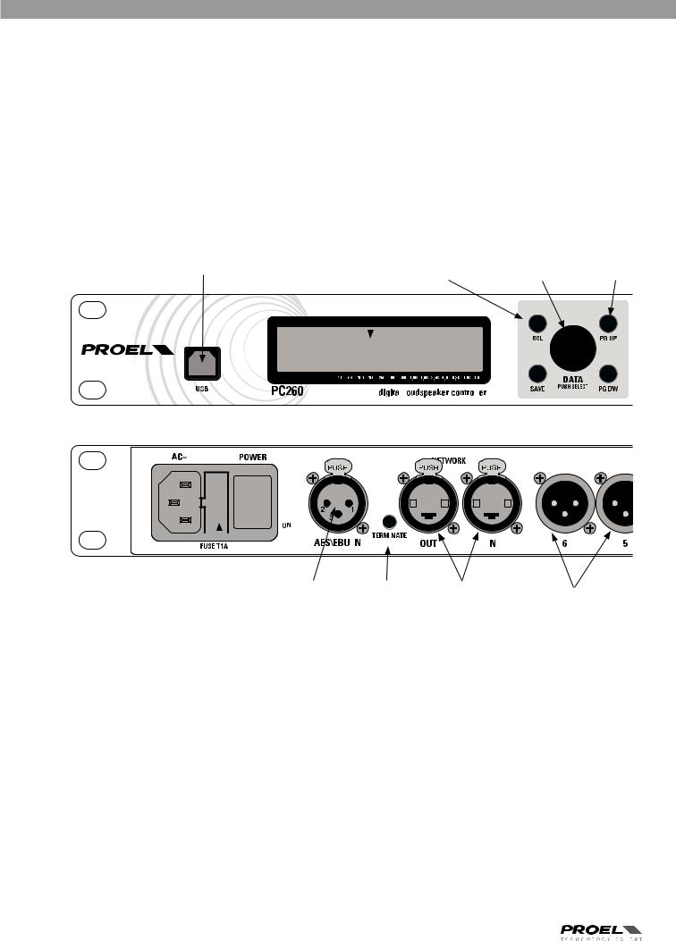
OVERVIEW
USB PORT |
display |
preset recall |
|
data value select |
page |
||||||||||||||||||||||||
|
|
and save |
|
|
|
and input |
scroll |
||||||||||||||||||||||
|
|
|
|
|
|
|
|
|
|
|
|
|
|
||||||||||||||||
|
|
|
|
|
|
|
|
|
|
|
|
|
|
|
|
|
|
|
|
|
|
|
|
|
|
|
|
|
|
|
|
|
|
|
|
|
|
|
|
|
|
|
|
|
|
|
|
|
|
|
|
|
|
|
|
|
|
|
|
|
|
|
|
|
|
|
|
|
|
|
|
|
|
|
|
|
|
|
|
|
|
|
|
|
|
|
|
|
|
|
|
|
|
|
|
|
|
|
|
|
|
|
|
|
|
|
|
|
|
|
|
|
|
|
|
|
|
|
|
|
|
|
|
|
|
|
|
|
|
|
|
|
|
|
|
|
|
|
|
|
|
|
|
|
|
|
|
|
|
|
|
|
|
|
|
|
|
|
|
|
|
|
|
|
|
|
|
|
|
|
|
|
|
|
|
|
|
|
|
|
|
|
|
|
|
|
|
|
|
|
|
|
|
|
|
|
|
|
|
|
|
|
|
|
|
|
|
|
|
|
|
|
|
|
|
|
|
|
|
|
|
|
|
|
|
|
|
|
|
|
|
|
|
|
|
|
|
|
|
|
|
|
|
|
|
|
|
|
|
|
|
|
|
|
|
|
|
|
|
|
|
|
|
|
|
|
|
|
|
|
|
|
|
|
|
|
|
|
|
|
|
|
|
|
|
|
|
|
|
|
|
|
|
|
|
|
|
|
|
|
|
|
|
|
|
|
|
|
|
|
|
|
|
|
|
|
|
|
|
|
|
|
|
|
|
|
|
|
|
|
|
|
|
|
|
|
|
|
|
|
|
|
|
|
|
|
|
|
|
|
|
|
|
|
|
|
|
|
|
|
|
|
|
|
|
|
|
|
|
|
|
|
|
|
|
|
|
|
|
|
|
|
|
|
|
|
|
|
|
|
|
|
|
|
|
|
|
|
|
|
|
|
|
|
|
|
|
|
|
|
|
|
|
|
|
|
|
|
|
|
digital audio |
|
|
terminate |
|
pronet network |
|
|
|||
mains ac power |
output connections |
||||||||||||||||
|
input |
|
button |
connections |
|||||||||||||
|
|
|
|
|
|
|
|
|
|||||||||
8

ESCAPE BUTTON PROCESSING MENU |
CHANNEL SELECT |
LED METERS |
|
|
CHANNEL MUTE |
|
|
|
EXTERNAL MIC |
|||||||||||||||||||||||||||||||
|
|
|
|
|
|
|
BUTTONS |
|
|
|
|
|
|
|
|
|
|
BUTTONS |
|
|
INPUT FOR RTA |
|||||||||||||||||||
|
|
|
|
|
|
|
|
|
|
|
|
|
|
|
||||||||||||||||||||||||||
|
|
|
|
|
|
|
|
|
|
|
|
|
|
|
|
|
|
|
|
|
|
|
|
|
|
|
|
|
|
|
|
|
|
|
|
|
|
|
|
|
|
|
|
|
|
|
|
|
|
|
|
|
|
|
|
|
|
|
|
|
|
|
|
|
|
|
|
|
|
|
|
|
|
|
|
|
|
|
|
|
|
|
|
|
|
|
|
|
|
|
|
|
|
|
|
|
|
|
|
|
|
|
|
|
|
|
|
|
|
|
|
|
|
|
|
|
|
|
|
|
|
|
|
|
|
|
|
|
|
|
|
|
|
|
|
|
|
|
|
|
|
|
|
|
|
|
|
|
|
|
|
|
|
|
|
|
|
|
|
|
|
|
|
|
|
|
|
|
|
|
|
|
|
|
|
|
|
|
|
|
|
|
|
|
|
|
|
|
|
|
|
|
|
|
|
|
|
|
|
|
|
|
|
|
|
|
|
|
|
|
|
|
|
|
|
|
|
|
|
|
|
|
|
|
|
|
|
|
|
|
|
|
|
|
|
|
|
|
|
|
|
|
|
|
|
|
|
|
|
|
|
|
|
|
|
|
|
|
|
|
|
|
|
|
|
|
|
|
|
|
|
|
|
|
|
|
|
|
|
|
|
|
|
|
|
|
|
|
|
|
|
|
|
|
|
|
|
|
|
|
|
|
|
|
|
|
|
|
|
|
|
|
|
|
|
|
|
|
|
|
|
|
|
|
|
|
|
|
|
|
|
|
|
|
|
|
|
|
|
|
|
|
|
|
|
|
|
|
|
|
|
|
|
|
|
|
|
|
|
|
|
|
|
|
|
|
|
|
|
|
|
|
|
|
|
|
|
|
|
|
|
|
|
|
|
|
|
|
|
|
|
|
|
|
|
|
|
|
|
|
|
|
|
|
|
|
|
|
|
|
|
|
|
|
|
|
|
|
|
|
|
|
|
|
|
|
|
|
|
|
|
|
|
|
|
|
|
|
|
|
|
|
|
|
|
|
|
|
|
|
|
|
|
|
|
|
|
|
|
|
|
|
|
|
|
|
|
|
|
|
|
|
|
|
|
|
|
|
|
|
|
|
|
|
|
|
|
|
|
|
|
|
|
|
|
|
|
|
|
|
|
|
|
|
|
|
|
|
|
|
|
|
|
|
|
|
|
|
|
|
|
|
|
|
|
|
|
|
|
|
|
|
|
|
|
|
|
|
|
|
|
|
|
|
|
|
|
|
|
|
|
|
|
|
|
|
|
|
|
|
|
|
|
|
|
|
|
|
|
|
|
|
|
output connections |
|
input pad button |
|
ground lift button |
|
input connections |
|
9

INTRODUCTION
The PROEL PC260 digital loudspeaker controller is based on the CORE DSP platform and features state-of-the-art signal processing, advanced functions and a very intuitive user interface, with a direct access to all the editing functions and remote control capability.. The 40bit floating point resolution and the 24bit AD/DA converters ensure a perfect signal integrity with a dynamic range in excess of 110dB, for a superior sonic performance..
PC260 includes a full set of functions and features 2 inputs (with AES digital input) and 6 outputs..
Each INPUT features 5 bands of full PARAMETRIC EQ (including parametric, shelving, notch, res.. HP and LP, allpass and bandpass), 28 bands of GRAPHIC EQ and 3 bands of an extremely versatile and powerful DYNAMIC EQ.. A fully programmable COMPRESSOR/ LIMITER and up to 600ms of delay are also available..
The OUTPUTS include any kind of crossover filters with slope up to 48dB per octave, together with 5 bands of PEQ, fully programmable COMPRESSOR/LIMITER and up to 600ms of delay..
Additional features include a fully assignable input/output routing and ganging, enviromental temperature compensation of delays, a GROUPING function and a 1/3 oct.. RTA with dedicated MIC input with phantom power..
The SPL Manager, specifically designed for the application in fixed installations, is a very powerful tool that allows to schedule, in 4 different scenes, 16 events on each input and output, including MUTE, level change, COMPRESSOR threshold change and PRESET change.. These events can be then performed automatically according to the internal real-time clock of the unit..
PC260 can be remotely controlled with PRONET software through the USB port on the front panel and it can be included in a PRONET network through the two RJ-45 connectors on the rear panel..
IMPORTANT
To achieve optimum performance and guard against damage to the processor, your sound system or yourself, please read, understand and follow all of the directions contained in this manual. Failure to do so may result in improper performance, loss or injury.
CONTROLS AND CONNECTIONS
FRONT PANEL
1. USB port
USB port for connection to a PC running Windows XP, Vista, Seven 32 or 64 bit.. Using the PRONET application, the PC260 can be operated, edited and configured for installation with an easy to use, intuitive interface..
Any available firmware updates downloadable from www..proel..com can be loaded via the USB port as well, allowing for easy in-field updates..
2. Display
The display allows for operation and editing of the PC260 without the need of a connected PC.. It works in conjunction with the buttons to operate, navigate and edit the parameters..
In Run time mode the top line it shows the model name, the network operation mode, the lock status, the battery status and the real time clock.. in The rest of the screen it displays the machine name, the name of the currently selected factory or user preset, the SPLM status and the routing..
Pressing the RCL or SAVE buttons switches to their respective preset menus..
Pressing a processing menu button switches the display to their respective parameters page..
The contrast is set automatically.
3. Preset buttons RCL (Recall)
Press the RCL button to enter the Recall Preset menu (the RCL button lights).. Use the DATA knob to scroll the any factory or user preset and push it to recall the selected preset into current memory.. Pushing the DATA knob completes the preset load operation and returns the LCD display to Run time mode.. To exit without recalling a preset, press ESC..
SAVE
Press the SAVE button to enter the Save Preset manu (the SAVE button lights).. In this menu edited presets can be named and saved to a user preset location.. Use the DATA knob to choose the user memory location, to enter the preset name, then complete the saving operation pressing SAVE again.. To exit without storing the current preset, press ESC..
4. DATA entry knob
The DATA knob is used to scroll and select presets and to scroll and edit data parameters and values..
5. PG UP - PG DW buttons
Use these buttons to navigate through the menus pages.. The number of the page is diplayed in the right upper corner of the screen (the button cycles through all available pages)..
10
6. ESC button
Press this button to exit from the current menu and return to the Run time mode screen..
7. Processing menu buttons ROUTING
Use the ROUTING button to enter the routing menu (the ROUTING button lights).. In this menu you can set the signal path for each output..
LEV - level setting
Use the LEV button to enter the levels menu (the LEV button lights).. In this menu you can set the level and phase for each input and output..
XOVER - crossover filters
Use the XOVER button to enter the crossover menu (the XOVER button lights).. In this menu you can set the HP or LP filter parameters for each output..
DELAY
Use the DELAY button to enter the delay menu (the DELAY button lights).. In this menu you can set the delay time for each input and output..
SETUP
Use the SETUP button to enter the setup menu (the SETUP button lights).. In this menu you can set the various general parameters..
GEQ - graphic equalizer
Use the GEQ button to enter the graphic equalizer menu (the GEQ button lights).. In this menu you can set the equalization of each input..
PEQ - parametric equalizer
Use the PEQ button to enter the parametric equalizer screen (the PEQ button lights).. In this screen you can set the equalization of each input and output..
DEQ - dynamic equalizer
Use the DEQ button to enter the dynamic equalizer screen (the DEQ button lights).. In this screen you can set the dynamic equalization of each input..
DYN - dynamic processors
Use the DYN button to enter the dynamic menu (the DYN button lights).. In this menu you can set the signal dynamic processing, compression and limiting, of each input and output..
SPLM - level manager
Use the SPLM button to enter the level manager menu (the SPLM button lights).. In this menu you can set the level management for each input and output..
RTA - real time analyzer
Use the RTA button to enter the analyzer menu (the RTA button lights).. In this menu you can set the level for the RTA MIC input..
8. Input meters
The input meters monitor the input level of either analog or AES-EBU inputs, depending on the input mode set in the Setup Menu.. Optimal signal-to-noise performance is obtained when the average input level consistently lights the -12dBu (green) and intermittently lights the -6dBu (Yellow) LED indicators.. As the PC260 is a digital audio device, the digital clipping produces very unpleasant results, so the Clip (red) LED should never light.. If the PC260's input does clip, reduce the output level of the connected mixer.. The -6dB PAD button at the rear panel can be used for adjusting the input level also..
9. A - B input MUTE buttons
Each input channel has a lighted Mute button.. Pressing the Mute button turns off the input of that channel.. The button lights red as an alert.. Press the Mute button again to restore the output channel’s signal..
10. A - B input EDIT buttons
Use these buttons to access the editing of the input's parameter (the buttons light blue when pressed). . Pressing these buttons while in Run time mode, you enter the LEVEL menu (the LEV button also lights) where you can adjust the level of the selected input.. If a processing button, such as DELAY, GEQ, PEQ, DEQ, DYN, has been previuosly selected, pressing the edit button you choose the channel to process..
11. Output meters
Each output channel has a four-segment VU meter.. Meter withdrawal point can be pre or post mute, as set on SETUP page.. The red segment indicates that limiting is being applied to the output channel if the limiter is engaged or, if the limiter is disabled, indicates clipping of the D/A converters, which should be avoided by adjusting the Output Level..
It is important to understand how the meters work and what they are displaying.. The Output Levels are displayed as “dB to Limiter Threshold”.. In other words, the meters will display the headroom between the output level and the limiter threshold.. When viewed in conjunction with the gain reduction meters in the dynamic menu of the selected channel (use DYN button), this provides a complete display of level and headroom before and after limiting has been engaged to allow system levels to be optimized.. This also means that the output metering will be displayed differently depending on the limiter threshold setting..
12. Output MUTE buttons
Each output channel has a lighted Mute button.. Pressing the Mute button turns off the output of that channel.. The button lights red as an alert.. Press the Mute button again to restore the output channel’s signal..
13. Output EDIT buttons
Use these buttons to access the editing of the output's parameter (the buttons light blue when pressed).. Pressing these buttons while in Run time mode, you enter the LEVEL menu (the LEV button also lights) where you can adjust the level of the selected channel.. If a processing button, such as XOVER, DELAY, PEQ, DYN, has been previuosly selected, pressing the edit button you choose the channel to process..
11
 Loading...