

Prince Castle DHB-DDB Installation Manual
OPERATING
INSTRUCTIONS
Dunkin Donuts Holding Bin
DHB-DDB
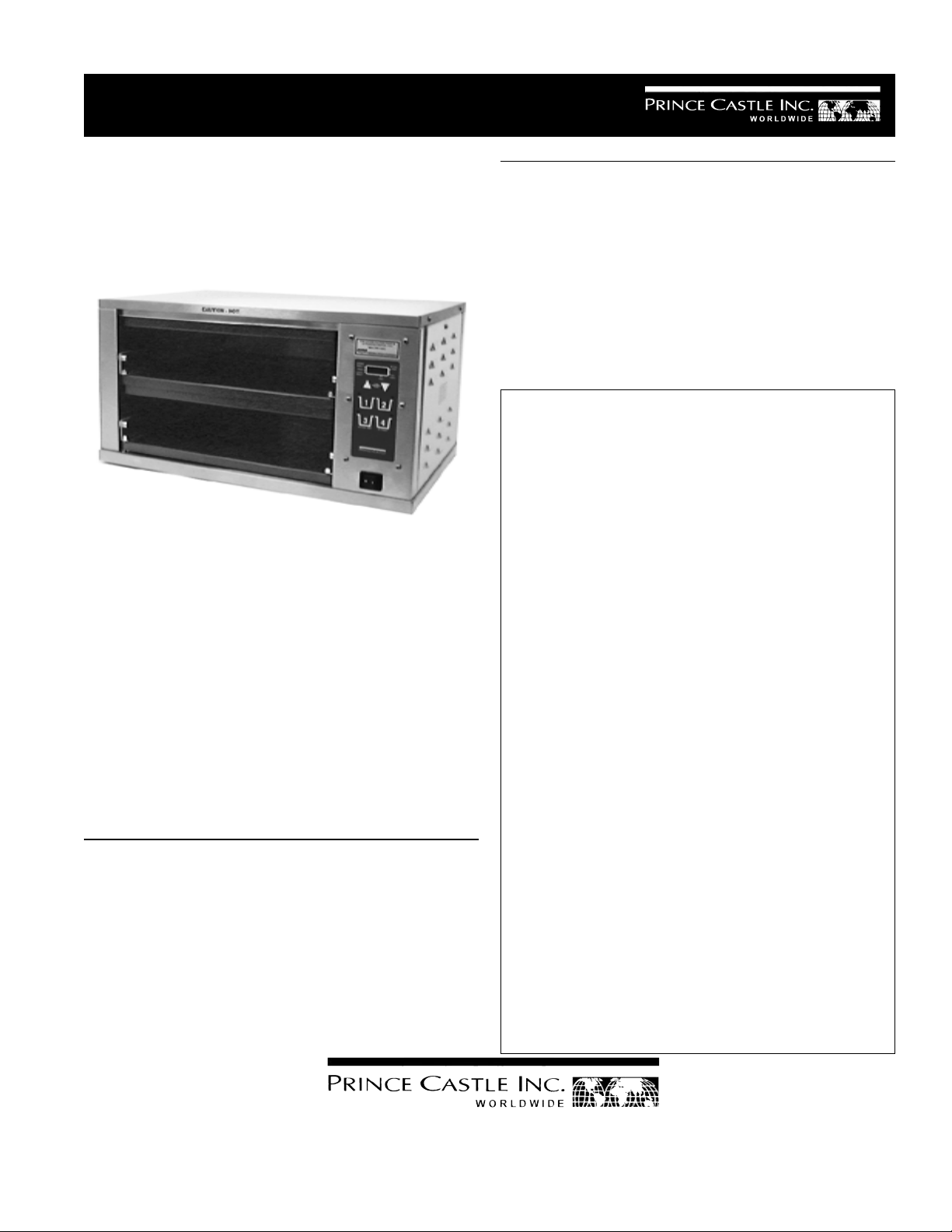
Prince Castle Food Holding Bins provide the capacity required for large foodservice operations while performing at
peak energy efficiency. Each unit features two individually
controlled holding chambers. New Reli-A-Temp™ infrared
heater technology holds product temperatures more consistent within the designated holding time than other types of
heating systems. This exclusive heater design spreads the
heat evenly over the entire food holding area, eliminating
edge drop off. Food is kept at the desired serving temperature.
TABLE OF CONTENTS PAGE
Installation..................................................................... 2
Controller Identification ................................................ 2
Operation ....................................................................... 3
Programming................................................................. 3
Calibration & Cleaning ................................................. 4
Troubleshooting Guide ................................................. 5
Exploded View & Parts List ........................................ 6
Wiring Diagram ............................................................. 8
LIMITED WARRANTY
This product is warranted to be free from defects in
material and/or workmanship for a period of two (2)
years from date of original installation not to exceed
30 months from date of shipment from our factory .
P.C. Boards and Heaters are warranted for three (3)
years from date of installation, not to exceed 42
months from date of shipment from our factory.
This warranty covers on-location service (i.e., trip
charges and/or mileage). Travel mileage is limited
to 100 miles round trip (one trip per warranty) from
an authorized service agency or its sub-service
agency.
Any component which proves to be faulty in material
and/or workmanship will be replaced or repaired (at
the option of Prince Castle, Inc.) without cost to the
customer for parts or labor.
This warranty is subject to the following exceptions/
conditions:
z Any use of non-genuine Prince Castle spare
parts voids this warranty.
ELECTRICAL SPECIFICATIONS
Voltage 120
Watts 1550
Hertz 50/60
Amps 12.9
355 East Kehoe Blvd. z Carol Stream, IL 60188
Printed in 1999
Prince Castle Inc.
Tel: (630) 462-8800 z Fax: (630) 462-1460
Toll Free: 1-800-PCASTLE
z All labor shall be performed by an authorized
Prince Castle Service Agent during regular working hours. Overtime premium will not be covered.
z Damage caused by carelessness, neglect, and/
or abuse (e.g., dropping, tampering or altering
parts), equipment damaged in shipment, by fire,
flood or an act of God is not covered under this
warranty.
542-508
INSTALLATION
1. After you have removed the bin from the carton,
inspect the unit for signs of damage. If there is
damage to the unit:
z Notify carrier within 24 hours after delivery.
TEMPERATURE MODE FUNCTIONS
UPPER SHELF LED: When lit, indicates that the
temperature displayed is for one of the upper shelf
heaters, a U will appear in the display for the upper
heater, a L for the lower heater.
z Save carton and packaging materials for inspec-
tion purposes.
z Contact your local dealer, or if purchased
directly,the Prince Castle Customer Sales Depart ment at 1-800-722-7853 to arrange for a replace ment to be sent.
2. Verify that all parts have been received. A rack kit
should be received with bin.
3. Remove all packaging and the white protective
covering from the bin.
3. Insert the racks into the appropriate heater compartment.
4. Plug unit into an appropriate 120 Volt outlet (NEMA
L5-15P).
NOTE: When installing this bin, it should be confirmed
that the ambient temperatures at the mounting
site do not exceed 110 F.
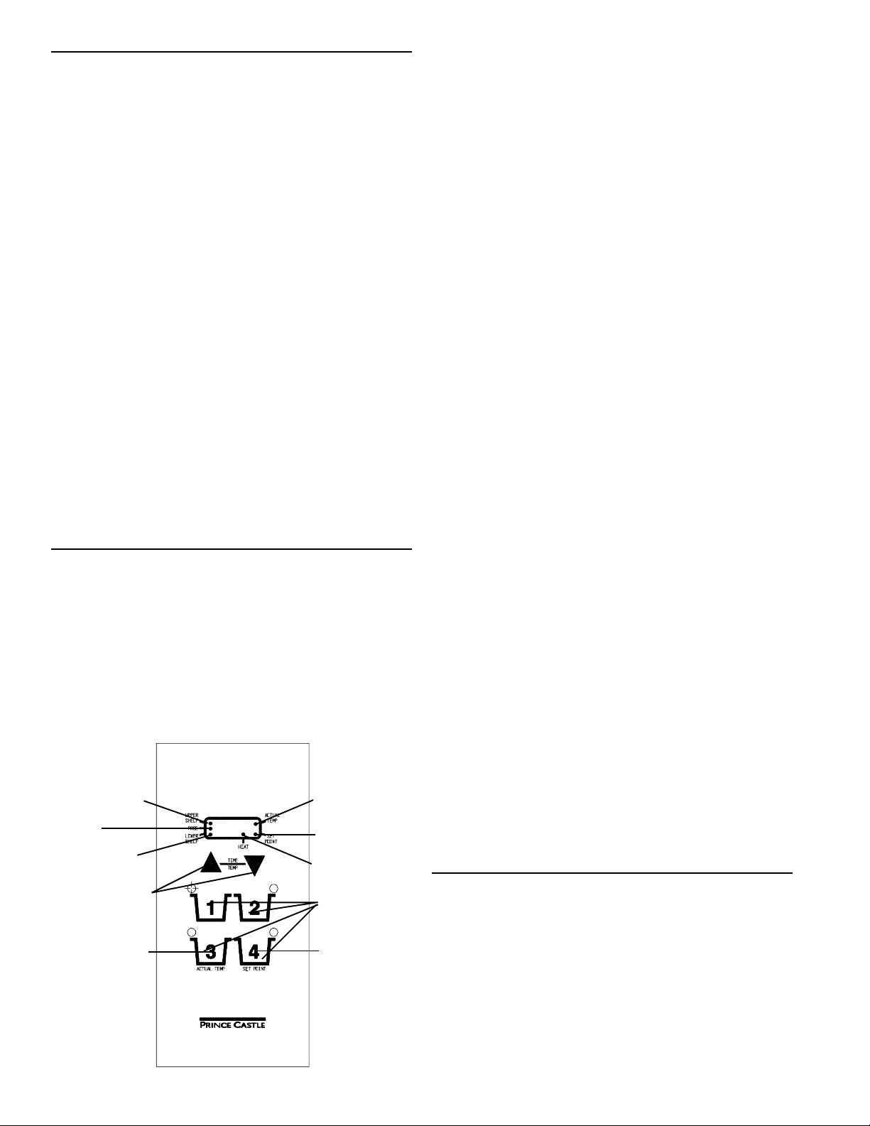
CONTROL PANEL IDENTIFICATION
LOWER SHELF LED:When lit, indicates that the
temperature displayed is for one of the lower shelf
heaters, a U will appear in the display for the upper
heater, a L for the lower heater.ACTUAL TEMP LED:
When lit, indicates that the actual temperaure for the
selected heater is displayed.
SET POINT LED: When lit, indicates that the Set
Point Temeparure for the selected heater is displayed.
PROG LED: When lit, indicates the controller is in
the Program Mode.
HEAT LED: When lit, indicates that the selected
heater is cycling on.
UP ARROW or DOWN ARROW: Pressing either
button will allow the operator to select another
heater assembly for display or programming purposes.
ACTUAL TEMP BUTTON: When pressed, the actual
temperature for the selected heater will appear in the
display.
The DHB-DDA Dedicated Holding Bin has two
different modes of operation, the Time Mode and
the Temperature Mode. The individual buttons on
the control panel will have different functions dependant upon which mode the unit is in. The unit will be
in the Temperature Mode when initially switched on.
Program
LED
Up & Down
Actual Temp
Upper
Shelf
LED
Lower
Shelf
LED
Arrows
Button
Actual Temp
LED
Set Point
LED
Heat LED
Pan Timer
Buttons
Set Point
Button
SET POINT BUTTON: When pressed, the set point
temperature for the selected heater will appear in the
display.
SET POINT BUTTON and DOWN ARROW: When
pressed simultaneously, will enter the program mode
for changing the set point temperature for the selected heater assembly.
UP ARROW and DOWN ARROW: When pressed &
held simultaneously, will switch controller from
Temperature Mode to Time Mode or Time Mode to
Temperature Mode.
OPERATION
1. Turn on power switch.
2. Allow heater assemblies to reach operating
temperatures. The four heater assemblies are
factory preset at 160 F.
3. Press and hold both the UP ARROW and DOWN
ARROW to change the controller to the Time
Mode. “----” will appear in the display.
2

4. Place a pan of product into the appropriate rack
location.
5. Press the appropriate Pan Timer Button. The red
LED for the Pan Timer Button will flash and the
programmed holding time for that product will
begin to countdown. Note: All four Pan Timer
Buttons are preset for 30 minutes. The countdown
time will be displayed in hours and minutes, until
the time reaches 10 minutes. At that point, the
display will change to minutes and seconds.
2. Press either the UP ARROW or the DOWN
ARROW to select the proper heater assembly.
3. Press either the ACTUAL TEMP or SET POINT
BUTTON to display the desired temperature.
4. Press and hold both the UP ARROW and DOWN
ARROW for 5 seconds to return to the Time
Mode.
PROGRAMMING
6. If more than one Pan Timer Button is activated,
the active pan timer with the least amount of
countdown time remaining will flash its LED
indicator and the time remaining will appear in the
display. The other active pan timers will have a
solid red LED.
7. Remove product from the pan as necessary.
8. At the end of the countdown sequence, an audio
alarm will sound and the display will flash “END”.
Press the Pan Timer Button with the flashing LED
to cancel the audio alarm.
9. Remove that pan and discard the remaining
product in it.
Note: Pan Timers can only be activated or deactivated when the controller is in the Time Mode.
To Cancel An Active Pan Timer When Pan Is
Empty:
Press the Pan Timer Button three times. The Pan
Timer LED will shut off and the display will revert
back to show the Pan Timer with the least amount of
countdown time remaining.
To Program A Set Point Temperature Change:
1. Change the controller to the Temperature Mode, if
it is not already in it, by pressing and holding
both the UP ARROW and DOWN ARROW for 5
seconds. The display will change to show the
currently selected heater assembly, indicated by
the LED being lit next to either the UPPER
SHELF or LOWER SHELF and a U or L
appearring in the display.
2. Press either the UP ARROW or DOWN ARROW
until the appropriate heater assmbly is selected.
3. Press and hold the SET POINT Button and then
the DOWN ARROW for 5 seconds. The PROG
LED will light up, indicating the controller is in
the program mode.
4. Press either the UP ARROW or DOWN ARROW
until the desired temperaure is reached.
5. Press the SET POINT button to store the change
and return to the Temperature mode.
6. Follow the same steps to change any other Set
Point Temperatures.
To View The Remaining Countdown Time For An
Active Pan Timer:
The countdown time for the pan timer with the least
amount of time remaining will appear in the display.
To view the time remaining for another active pan
timer, press the pan timer button. The remaining
countdown time for that pan timer will appear in the
display. When the button is released the display will
revert back to the least remaining countdown time.
To View the Actual Or Set Point Temperature
For A Selected Heater:
1. When in the Time Mode, press and hold both
theDOWN ARROW and the UP ARROW for 5
seconds to change the controller to the Temperature Mode. The display will change to show the
actual temperature for the currently selected
heater.
Note: Each heater assembly can be programmed to
be off or from 150 F to 275 F.
To Program A Pan Timer Change:
NOTE: To program pan timer changes, the controller
must be in the Timer Mode. If the controller is in the
Temperature Mode, press and hold the UP ARROW
and DOWN ARROW for 5 seconds. (Times can be
programmed From “0” to 9:59 Hours.)
PAN TIMER #1
1. Press and hold Pan Timer Button #1 and then
the UP ARROW for approximately 6 seconds. The
program LED will light up and the display will
show the current countdown time for the channel.
3
 Loading...