

Pioneer x-rsm410dvh, x-rsm400dvh Service Manual
PIONEER CORPORATION 4-1, Meguro 1-chome, Meguro-ku, Tokyo 153-8654, Japan
PIONEER ELECTRONICS (USA) INC. P.O. Box 1760, Long Beach, CA 90801-1760, U.S.A.
PIONEER EUROPE NV Haven 1087, Keetberglaan 1, 9120 Melsele, Belgium
PIONEER ELECTRONICS ASIACENTRE PTE. LTD. 253 Alexandra Road, #04-01, Singapore 159936
PIONEER CORPORATION
2009
X-RSM400DV
For details, refer to "Important Check Points for good servicing".
DVD MINI COMPONENT SYSTEM
X-RSM400DV
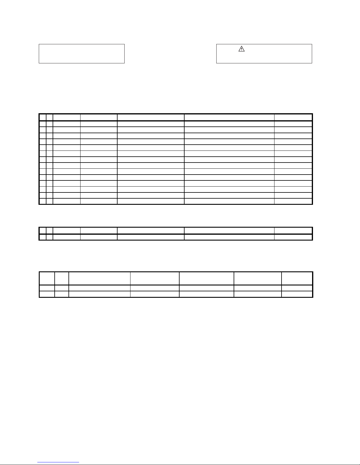
THIS MANUAL IS APPLICABLE TO THE FOLLOWING MODEL(S) AND TYPE(S).
ORDER NO.
RRV4011
Model Type Power Requirement
X-RSM400DV LXCN AC 110 V to 240 V 3 &&&&######LE LE : ASEAN
X-RSM400DV
X-RSM400DV
DXCN AC 110 V to 240 V 4 &&&&######ME ME : LATIN AMERICA
DXCNRI AC 110 V to 240 V 2 &&&&######RB RB : MIDDLE EAST
DVD
Region No.
Serial No. Remarks
T-ZZV NOV.
2009 Printed in Japan
1
A
B
2 3 4
LASER DIODE CHARACTERISTICS
C
D
E
For DVD Wave Length: 656 nm
Operating output: 0.1 mW CW, Class 1
Maximum output: Class 1
For CD Wave Length: 789 nm
Operating output: 0.15 mW CW, Class 1
Maximum output: Class 1
F
2
1
X-RSM400DV
2 3 4
5
[Important Check Points for Good Servicing]
In this manual, procedures that must be performed during repairs are marked with the below symbol.
Please be sure to confirm and follow these procedures.
1. Product safety
Please conform to product regulations (such as safety and radiation regulations), and maintain a safe servicing environment by
following the safety instructions described in this manual.
1 Use specified parts for repair.
Use genuine parts. Be sure to use important parts for safety.
2 Do not perform modifications without proper instructions.
Please follow the specified safety methods when modification(addition/change of parts) is required due to interferences such as
radio/TV interference and foreign noise.
3 Make sure the soldering of repaired locations is properly performed.
When you solder while repairing, please be sure that there are no cold solder and other debris.
Soldering should be finished with the proper quantity. (Refer to the example)
4 Make sure the screws are tightly fastened.
Please be sure that all screws are fastened, and that there are no loose screws.
5 Make sure each connectors are correctly inserted.
Please be sure that all connectors are inserted, and that there are no imperfect insertion.
6 Make sure the wiring cables are set to their original state.
Please replace the wiring and cables to the original state after repairs.
In addition, be sure that there are no pinched wires, etc.
7 Make sure screws and soldering scraps do not remain inside the product.
Please check that neither solder debris nor screws remain inside the product.
8 There should be no semi-broken wires, scratches, melting, etc. on the coating of the power cord.
Damaged power cords may lead to fire accidents, so please be sure that there are no damages.
If you find a damaged power cord, please exchange it with a suitable one.
9 There should be no spark traces or similar marks on the power plug.
When spark traces or similar marks are found on the power supply plug, please check the connection and advise on secure
connections and suitable usage. Please exchange the power cord if necessary.
a Safe environment should be secured during servicing.
When you perform repairs, please pay attention to static electricity, furniture, household articles, etc. in order to prevent injuries.
Please pay attention to your surroundings and repair safely.
2. Adjustments
To keep the original performance of the products, optimum adjustments and confirmation of characteristics within specification.
Adjustments should be performed in accordance with the procedures/instructions described in this manual.
4. Cleaning
For parts that require cleaning, such as optical pickups, tape deck heads, lenses and mirrors used in projection monitors, proper
cleaning should be performed to restore their performances.
3. Lubricants, Glues, and Replacement parts
Use grease and adhesives that are equal to the specified substance.
Make sure the proper amount is applied.
5. Shipping mode and Shipping screws
To protect products from damages or failures during transit, the shipping mode should be set or the shipping screws should be
installed before shipment. Please be sure to follow this method especially if it is specified in this manual.
6 7 8
A
B
C
D
5
X-RSM400DV
6 7 8
E
F
3
SECTION 5. DIAGNOSIS CONNECTION ………………………...….…..…………….. 5-1
1-1
SECTION 1. GENERAL
SERVICING PRECAUTIONS
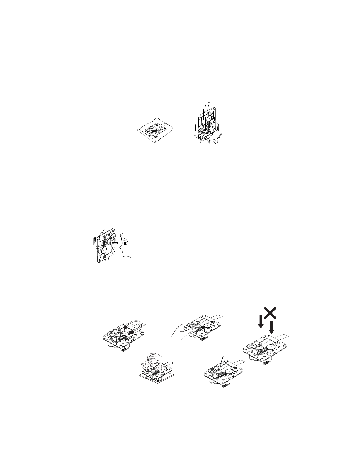
NOTES REGARDING HANDLING OF THE PICK-UP
1. Notes for transport and storage
1) The pick-up should always be left in its conductive bag until immediately prior to use.
2) The pick-up should never be subjected to external pressure or impact.
Storage in conductive bag
2. Repair notes
1) The pick-up incorporates a strong magnet, and so should never be brought close to magnetic mate-
rials.
2) The pick-up should always be handled correctly and carefully, taking care to avoid external pressure
and impact. If it is subjected to strong pressure or impact, the result may be an operational malfunction and/or damage to the printed-circuit board.
3) Each and every pick-up is already individually adjusted to a high degree of precision, and for that
reason the adjustment point and installation screws should absolutely never be touched.
4) Laser beams may damage the eyes!
Absolutely never permit laser beams to enter the eyes!
Also NEVER switch ON the power to the laser output part (lens, etc.) of the pick-up if it is damaged.
NEVER look directly at the laser beam, and don’t allow
contact fingers or other exposed skin.
5) Cleaning the lens surface
If there is dust on the lens surface, the dust should be cleaned away by using an air bush (such as
used for camera lens). The lens is held by a delicate spring. When cleaning the lens surface, therefore, a cotton swab should be used, taking care not to distort this.
Drop impact
Magnet
6) Never attempt to disassemble the pick-up.
Spring by excess pressure. If the lens is extremely dirty, apply isopropyl alcohol to the cotton swab.
(Do not use any other liquid cleaners, because they will damage the lens.) Take care not to use too
much of this alcohol on the swab, and do not allow the alcohol to get inside the pick-up.
Pressure
Pressure
How to hold the pick-up
Cotton swab
Conductive Sheet
1-2
NOTES REGARDING COMPACT DISC PLAYER REPAIRS
1. Preparations
nents are sensitive to, and easily affected by, static electricity. If such static electricity is high voltage,
components can be damaged, and for that reason components should be handled with care.
must be taken, therefore, to avoid repair or storage where the temperature of humidity is high, where
strong magnetism is present, or where there is excessive dust.
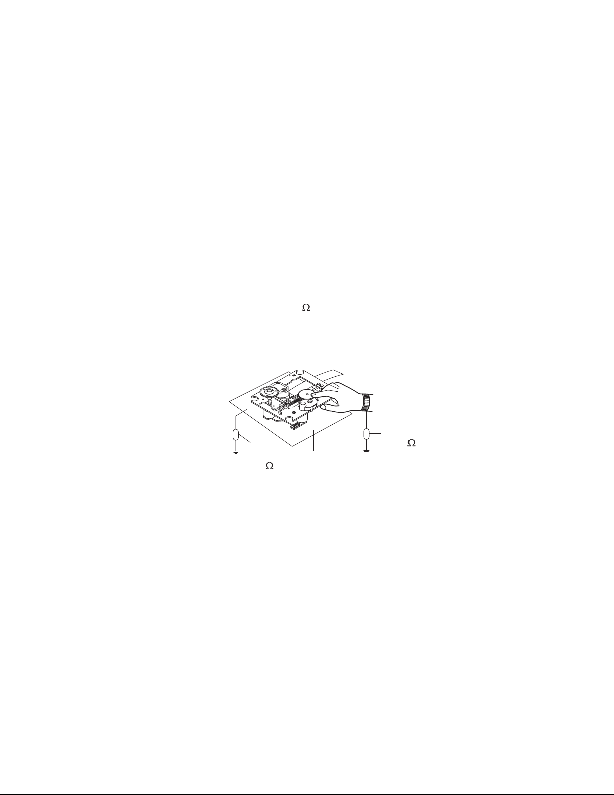
2. Notes for repair
1) Before replacing a component part, first disconnect the power supply lead wire from the unit
2) All equipment, measuring instruments and tools must be grounded.
.dednuorg dna teehs evitcudnoc a htiw derevoc eb dluohs hcnebkrow ehT )3
When removing the laser pick-up from its conductive bag, do not place the pick-up on the bag.
(This is because there is the possibility of damage by static electricity.)
4) To prevent AC leakage, the metal part of the soldering iron should be grounded.
5) Workers should be grounded by an armband (1M
prevent static electricity changes in the clothing to escape from the armband.
7) The laser beam from the pick-up should NEVER be directly facing the eyes or bare skin.
)
Armband
-opmoc esehT .)edoid resal( pu-kcip eht sa llew sa sCI ynam taerg a etaroprocni sreyalp csid tcapmoC )1
eraC .stnenopmoc noisicerp-hgih rehto dna stnenopmoc lacitpo ynam fo desopmoc si pu-kcip ehT )2
ot redro ni ,gnihtolc htiw tcatnoc ni emoc ot pu-kcip resal eht timrep ot ton nekat eb dluohs eraC )6
Resistor
)
(1 M
Conductive
Sheet
Resistor
(1 M
)
1-3
SAFETY PRECAUTIONS
Electrostatically Sensitive Devices (ESD)
Some semiconductor (solid state) devices can be damaged easily by static electricity. Such components
commonly are called E lectrostatically Sensitive Devices (ESD). E xamples of typical E SD devices are integrated
circuits and some field-effect transistors and semiconductor chip components. The following techniques should
be used to help reduce the incidence of component damage caused by static electricity.
1. Immediately before handling any semiconductor component or semiconductor-equipped assembly, drain off
any electrostatic charge on your body by touching a known earth ground. Alternatively, obtain and wear a
commercially available discharging wrist strap device, which should be removed for potential shock reasons
prior to applying power to the unit under test.
2. After removing an electrical assembly equipped with ESD devices, place the assembly on a conductive
surface such as aluminum foil, to prevent electrostatic charge buildup or exposure of the assembly.
3. Use only a grounded-tip soldering iron to solder or unsolder ESD devices.
4. Use only an anti-static solder removal device. Some solder removal devices not classified as " anti-static" can
generate electrical charges sufficient to damage ESD devices.
5. Do not use freon-propelled chemicals. These can generate electrical charges sufficient to damage ESD
devices.
6. Do not remove a replacement ESD device from its protective package until immediately before you are
ready to install it. (Most replacement ESD devices are packaged with leads electrically shorted together by
conductive foam, aluminum foil or comparable conductive materials).
7. Immediately before removing the protective material from the leads of a replacement E SD device, touch the
protective material to the chassis or circuit assembly into which the device will by installed.
CAUTION : BE SURE NO POWER IS APPLIED TO THE CHASSIS OR CIRCUIT, AND OBSERVE ALL OTHER
SAFETY PRECAUTIONS.
8. Minimize bodily motions when handing unpackaged replacement ESD devices. (Otherwise harmless motion
such as the brushing together of your clothes fabric or the lifting of your foot from a carpeted floor can generate
static electricity sufficient to damage an ESD device).
CAUTION. GRAPHIC SYMBOLS
THE LIGHTNING FLASH WITH APROWHEAD SYMBOL. WITHIN AN EQUILATERAL TRIANGLE, IS
INTENDED TO ALERT THE SERVICE PERSONNEL TO THE PRESENCE OF UNINSULATED
“DANGEROUS VOLTAGE” THAT MAY BE OF SUFFICIENT MAGNITUDE TO CONSTITUTE A RISK OF
ELECTRIC SHOCK.
THE EXCLAMATION POINT WITHIN AN EQUILATERAL TRIANGLE IS INTENDED TO ALERT THE
SERVICE PERSONNEL TO THE PRESENCE OF IMPORTANT SAFETY INFORMATION IN SERVICE
LITERATURE.
1-4
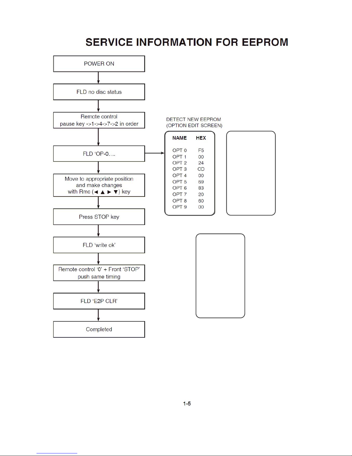
When Option Code Assembly
is replaced, perform this
Option Code setting.
NAME HEX
OPT 0 F5
OPT 1 00
OPT 2 A4
OPT 3 AD
OPT 4 00
OPT 5 09
OPT 6 83
OPT 7 20
OPT 8 60
OPT 9 00
X-RSM400DV/DXCN
NAME HEX
OPT 0 F5
OPT 1 00
OPT 2 A4
OPT 3 BD
OPT 4 00
OPT 5 69
OPT 6 83
OPT 7 20
OPT 8 60
OPT 9 00
X-RSM400DV/LXCN
X-RSM400DV/DXCNRI

PROGRAM DOWNLOAD GUIDE
Caution) Do not perform any other work such as disconnecting USB device, switching to the Function
and turning off the power while downloading it to the set.
The USB device should be disconnected after completing the download.
• AUDIO USB DOWNLOAD GUIDE
1. When the USB device is inserted on the USB function, is displayed on the screen after a while.
“File : MDT404_YYMMDDX.HEX” * x: version.
2. The message “Upgrade” is displayed while downloading.
3. The power is automatically turned off when downloading is completed.
• DVD USB DOWNLOAD GUIDE
The program file to download should be named as LG_MDT404XXX_YYMMDDX.rom.
- The downloaded file should be modified as LG_MDT404XXX_YYMMDDX.rom.
- After safely storing LG_MDT404XXX_YYMMDDX.rom at the USB device, perform the following steps.
1. When the USB device is inserted at the USB function, the screen is changed into downloading
screen.
2. When downloading is completed, the message “Completed” is displayed at the top left on the screen.
3. Turn on the power, press the SETUP button of the remote controller on the USB FUCTION. When
the SETUP window is displayed on the screen, move down once to select the DISPLAY menu. Go
to the TV Aspect on the right menu, move to “16:9”, enter “1397139” by using the numeric key of the
remote controller, and press the Enter key.
Then, the System Information screen is displayed. If not, retry the steps at the above.
4. When Step 3 is completed, press the Pause key of the remote controller.
5. Disconnect the power cord, and reconnect it after 5 seconds to complete downloading.
6. When the power is turned on, the language selection menu is initially displayed.
After selecting the desired language, press the SELECT/ENTER.
1-6

SPECIFICATIONS
General
Power supply AC 110 V~240 V, 50 Hz/60 Hz
Power consumption 65 W
gk 8.5 thgieW teN
External dimensions (WxHxD) 273 x 336 x 372 mm
Operating temperature 5 °C to 35 °C
Operating humidity 5% to 85 %
Tuner
FM Tuning Range 87.5 ~ 108.0 MHz
AM Tuning Range 530 ~ 1 700 KHz (DXCN), 531 ~ 1 602 KHz (LXCN/DXCNRI)
Amplifier
Output Power Front : 110 W x 2, Sub Woofer : 180 W
% 01 D.H.T
Frequency Response 42 ~ 20000 Hz
Signal-to-noise ratio 75 dB
DVD / CD player
Frequency response (audio) 40 ~ 20,000 Hz
Signal-to-noise ratio (audio) More than 75 dB (1 KHz)
Signal-to-noise ratio (video) More than 55 dB (1 KHz)
Dynamic range (audio) More than 80 dB
Video output 1.0 V (p-p), 75
Component Video output (Y) 1.0 V (p-p), 75
(Pb)/(Pr) 0.7 V (p-p), 75
Cassette tape player
F.F/REW Time 120 sec (C-60)
Frequency Response 250 ~ 8000 Hz
Signal to Noise Ratio 43 dB
Channel Separation 45 dB (P/B) / 45 dB (R/P)
)1155-TTM( Bd 05 oitaR esarE
Speakers
Input Power 110 W
Max. Input Power 200 W
Net Dimensions (W x H x D) 220 x 336 x 296 mm
Net Weight (1EA) 4.5 kg
FRONT SPEAKER
rekaepS 2 yaW 2 epyT
4 ecnadepmI
SUBWOOFER SPEAKER
rekaepS 1 yaW 1
3
180 W
300 W
274 x 336 x 336 mm
6.0 kg
Designs and specifications are subject to change without pior notice.
1-7

1-8
EQUILATERAL TRIANGLE IS INTENDED
TO ALERT THE SERVICE PERSONNEL
TO THE PRESENCE OF IMPORTANT
SAFETY INFORMATION IN SERVICE
LITERATURE.
NOTES) THE EXCLAMATION POINT WITHIN AN
295
J
K
A26
273
267
250
270L
272B
271
464
272A
464
464
264
272D
270R
N
263
455
291
290
O
464
464
292
T
H
J
463
C
G
A41
K
464
F
E
D
293
294
DVD
N
482
L
M
L
B
M
CABLE2
A46
I
O
MAIN
A
464
B
CABLE3
272C
464
265
263
464
464
U
T
USB
CABLE1
464
253
451
CABLE7
E
P
A47
300
SMPS
CABLE8
D
A
289
P
277
R
275
464
S
2-1 2-2
277
274
S
F
Q
U
MIC
260
R
I
H
CABLE5
G
CABLE6
259
464
258
256
252
FRONT
A43
C
CABLE4
454
464
268
269
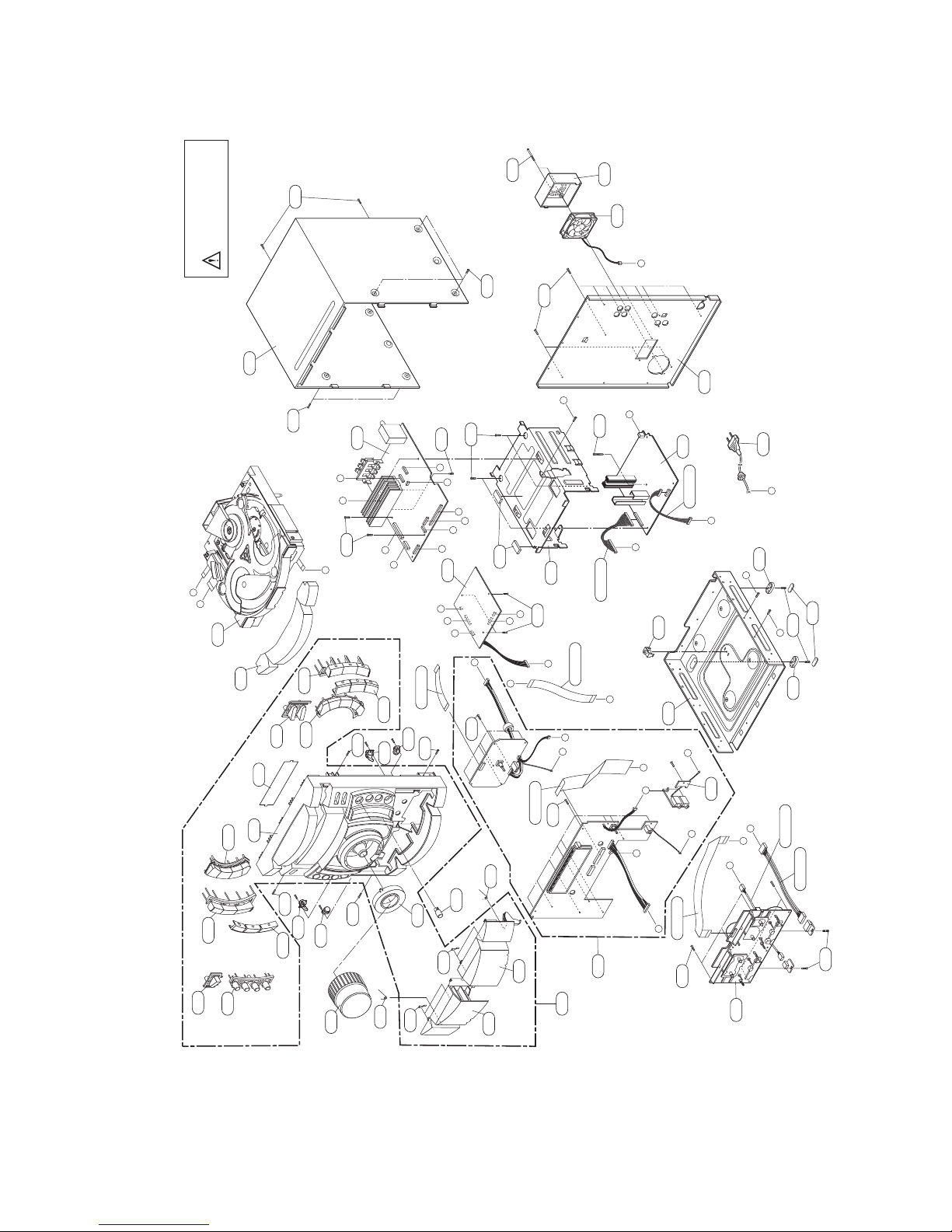
SECTION 2. EXPLODED VIEWS
1. CABINET AND MAIN FRAME SECTION
257
253
256
251
A42
A00
NOTES) Warning
NOTES) Parts that are shaded are critical
NOTES) With respect to risk of fire or
NOTES) electricial shock.
CABLE
455 1SZZR-0081B Screw,Customized 1SZZR-0081B FH + 300UM 25MM MS
NSP : Non SVC Parts
RUN DATE : 25-September-2009
CABLE4 EAD36212304 Cable,FFC AT12513260C03 260MM 1.25MM 13P
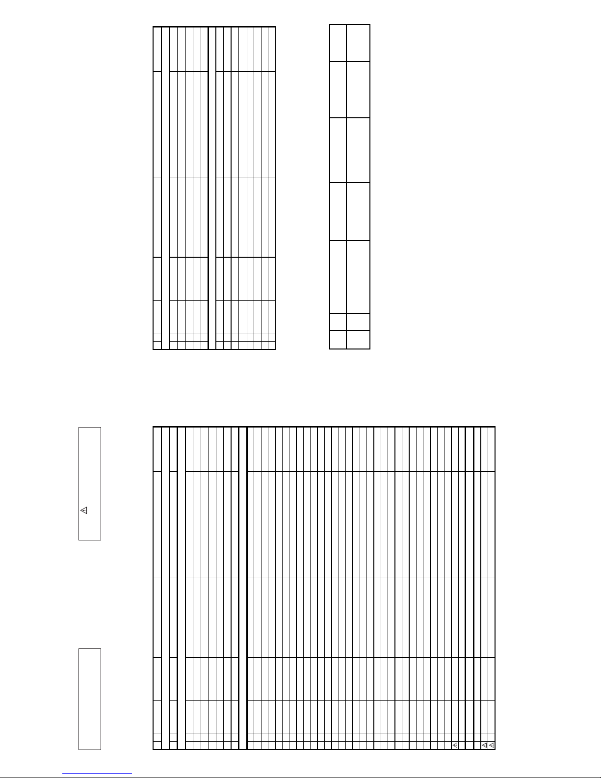
CONTRAST TABLE
X-RSM 400DV/DXCN, X-RSM40 0DV/DXCNRI and X -RSM400DV /LXCN a re co nstructed the same ex ce pt
A41 PCB Ass embly EBR64618201 EBR64618201 EBR64618202
A43 PCB Assembly, Front EBR64580201 EBR64580202 EBR64580202
A46 Option Code As sembly EBR64582101 EBR64582103 EBR64582102
Mark No. Symbol and Des cription X-RSM400DV/DXCN X-RSM400 DV/DXCNRI X-RSM400DV/LXCN Rem ark
for the follo win g :
2-3 2-4
EEPROM (OPTION HEX CODE) SCREW
/DXCN ( Latin America)
/LXCN ( ASEAN)
/DXCNRI ( Middle East)
NOTES) If you want to purchase
Flash memory, you must order
"IC100A, IC503A"
MODEL: X-RSM400DV
. CABINET & MAIN FRAME SECTION
ASSEMBLY PARTS SECTION
EBR64582101 Option Code Assembly F5 00 24 CD 00 69 83 20 60 00 451 353-025HAAA Screw,Customized TAPTITE 3X16 FZMY
A00 EAZ35771801 Audio Deck CWP42FF601 07 year Double A/S+ 463 1SZZR-0098G Screw,Customized 1SZZR-0098G FH + 3MM 8MM MSWR
A26 AFP70034802 Mechanism Assembly DVM-H1713 LG 3- DVD Short Dept NSP 464 1SZZR-0097K Screw,Customized 1SZZR-0097K BH + 3MM 10MM MSWR
S AL LOCA. NO. PART NO. DESCRIPTION SPECIFICATION REMARK S AL LOCA. NO. PART NO. DESCRIPTION SPECIFICATION REMARKS
PARTS SECTION
A43 EBR64580201 PCB Assembly,Front MDT404 FRONT TTL ASSY pioneer DXCN CABLE1 EAD43284604 Cable,FFC AT12536200C04 200MM 1.25MM 36P
A46 EBR64582101 Option Code Assembly F5 00 24 CD 00 69 83 20 60 00 DXCN CABLE2 EAD42219405 Cable,FFC AT10018180C03 180MM 1.00MM 18P
250 MGC61875802 Panel,Front MOLD HIPS 60HR HOME MDT404 MOL CABLE5 563-935H Harness,Single GIL-G-03 GIL-G-03 GIL-G-03 340
A47 EBR40198721 PCB Assembly,Power MDT404 HZ(450V) SMPS TTL ASSY CABLE3 6850R-HP06J Cable,FFC AT12516120C02 150MM 1.25MM 16P
251 MCV61851001 Door MOLD HIPS 60HR HOME MCT404 MOL CABLE6 EAD36203001 Harness,Single 8P-300mm, MCT352 A2507H02-08 A
252 MCV61851101 Door MOLD HIPS 60HR HOME MCT404 MOL CABLE7 EAD42218201 Harness,Single 15P-140MM (XD123) GIL-G GIL-G
253 442-085E Spring EXTRUSION STS 301 SPRIAL AUDIO CABLE8 EAD60517002 Harness,Single HS-LG08-006 A2507H02-08 A2507H
A41 EBR64618201 PCB Assembly MDT404 DVD TTL pioneer 482 353-025G Screw,Customized TAPTITE 3X10 FZMY
A42 AGL72950202 Panel Assembly,Audio HOME MDT404 FRONT ASSY(FOR PQ
256 MHY57751001 Spring PRESS SUS 0.3 PLATE MCV904 [TA
270R MBG62154801 Button MOLD ABS XG-568 HOME MCT404 MO
263 4901R-0002C Damper Assembly HOME HE902 NO
264 4974R-0041B Guide MOLD ABS HOME EJECT ASSY-L MOL
265 4974R-0042B Guide MOLD ABS HOME EJECT ASSY-R MOL
257 MEY61851101 Knob MOLD ABS MP-211 HOME MCT404 MO
258 MFB61870801 Lens MOLD PMMA HOME MCT404 LENS VOL
259 MEY61851201 Knob MOLD ABS MP-211 HOME MCT404 MO
267 MHK61843101 Sheet PRESS PC 0.5 CDT 118 39 0.5 FL
260 EAX61426702 PCB 1 MDT404/MCT404 JACK FR-1 1 1.
271 MBG62154501 Button MOLD ABS HF-380 HOME MCT404 MO
268 MBG62154401 Button MOLD ABS HF-380 HOME MCT404 MO
269 MBG62154601 Button MOLD ABS HF-380 HOME MCT404 MO
270L MBG62154701 Button MOLD ABS XG-568 HOME MCT404 MO
273 MCV61850901 Door MOLD HIPS 60HR HOME MCT404 MOL
274 MBS57893102 Chassis PRESS SECC 0.8 MCT354 PRESS CH NSP
275 MDP30320003 Foot CUTTING URETHANE HOME J10HD OT
277 MEG61846901 Holder MOLD ABS HF380 HOME RDD263(MCT
289 4930RC0033A Holder MOLD HIPS HOME [empty]LM-D6960
290 EAL60700902 Fan Module XRL4099007 3.5KRPM DC 12V 110M
291 MCK61994901 Cover MOLD HIPS HOME MCV904, MDS704
292 MGC57893209 Panel,Rear PRESS SECC 0.6 HOME MDT404 PRE
272A MFB61870601 Lens MOLD PMMA HOME MCT404 LENS AUX
272B MBG62154901 Button MOLD ABS HOME MCT404 MOLD BUTT
272C MFB61870702 Lens MOLD PMMA HOME MDT404 LENS TAP
272D MBG62155001 Button MOLD ABS HOME MCT404 MOLD BUTT
293 MCQ32777518 Damper CUTTING EVA HOME MDS714 OTHER
294 4810RL0696A Bracket PRESS SECC T0.8 HOME LX-D6960
295 MBN57893003 Case PRESS PCM 0.5 MDS714'S PRESS T
300 6410RCHZ05C Power Cord Assembly CE-503+H03VVH2-F 0.75/2C BLK 1
S AL LOCA. NO. PART NO. DESCRIPTION SPECIFICATION REMARKS
001 6768R-BP01P Deck Mechanism Parts 02-083-4257 02-083-4257 PIGEON
002 6768R-BP01N Deck Mechanism Parts 02-083-4258 02-083-4258 PIGEON
003 6768R-PP03A Deck Mechanism Parts 33-160-4309 PIGEON PRESS CASSE
A00 EAZ35771801 Audio Deck CWP42FF601 07 year Double A/S+
A01 6768RZUP01B Deck Mechanism Parts 50-093-31584 50-093-31584 PIGE
A02 6768R-EP05B Deck Mechanism Parts 50-093-41232 50-093-41232 PIGE
LOCA. NO. PART NO. DESCRIPTION SPECIFICATION
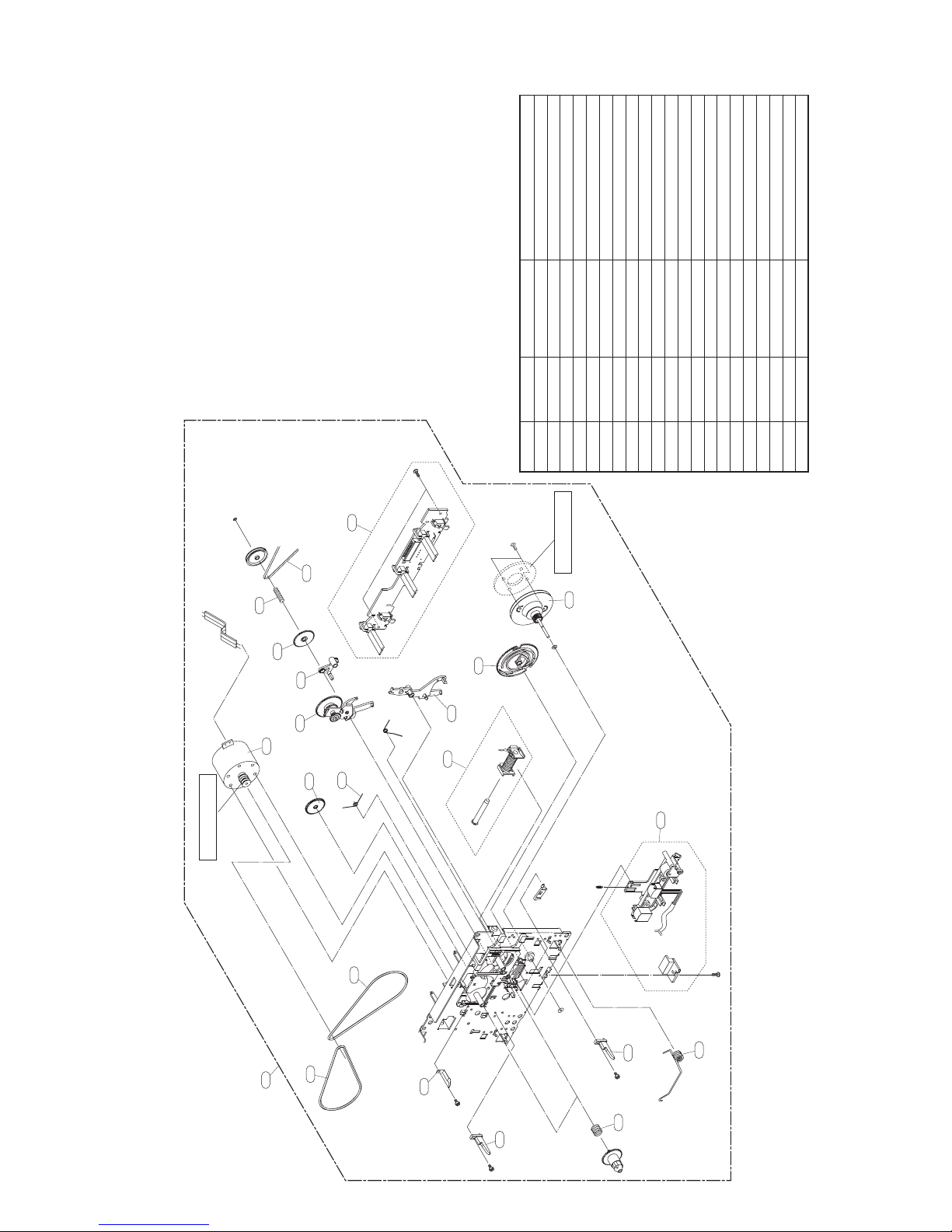
TAPE DECK (RIGHT A/S DECK) PARTS LIST
A01
RING FW MAYBE ADDED
020
FOR WOW FLUTTER WHEN NECESSARY
006 6768R-QP04B Deck Mechanism Parts 50-093-41585 50-093-41585 PIGE
011 6768R-SP01A Deck Mechanism Parts 01-081-4601 PIGEON SPRING CWL4
007 6768RZGP03A Deck Mechanism Parts 50-222-41226 PIGEON GEAR IDLER
008 6768R-SP01F Deck Mechanism Parts 01-082-4598 PIGEON SPRING CWL4
009 6768R-MP01C Deck Mechanism Parts 50-219-4014 PIGEON MOLD CWL44
013 6768RZSP02A Deck Mechanism Parts 01-082-4688 PIGEON SPRING
015 6768R-AP01A Deck Mechanism Parts 50-268-3016 PIGEON ARM CWL44
016 6768RZGP04B Deck Mechanism Parts 50-093-31582 50-093-31582 PIGE
017 6768R-AP01C Deck Mechanism Parts 50-239-4072 PIGEON ARM CWL44
018 6768R-GP01J Deck Mechanism Parts 50-222-4428 PIGEON GEAR CRL442
019 6768R-SP01P Deck Mechanism Parts 01-081-4678 PIGEON SPRING CRL4
020 6768R-BP01M Deck Mechanism Parts 02-083-4276 02-083-4276 PIGEON
022 6768RZVP03C Deck Mechanism Parts 50-093-4748 50-093-4748 PIGEON
023 6768RZGP05A Deck Mechanism Parts 50-221-31320 PIGEON GEAR ASSY
025 6768R-JP01J Deck Mechanism Parts 50-093-41518 50-093-41518 PIGE
BRASS MOTOR PULLEY MAYBE CHANGED
FOR WOW FLUTTER WHEN NECESSARY
019
006
A00
018
017
016
008
007
002
001
003
023
015
022
025
2-5 2-6
A02
009
013
2. TAPE DECK MECHANISM EXPLODED VIEW
2-1. TAPE DECK MECHANISM (A/S & A/S : RIGHT A/S DECK)
011
009
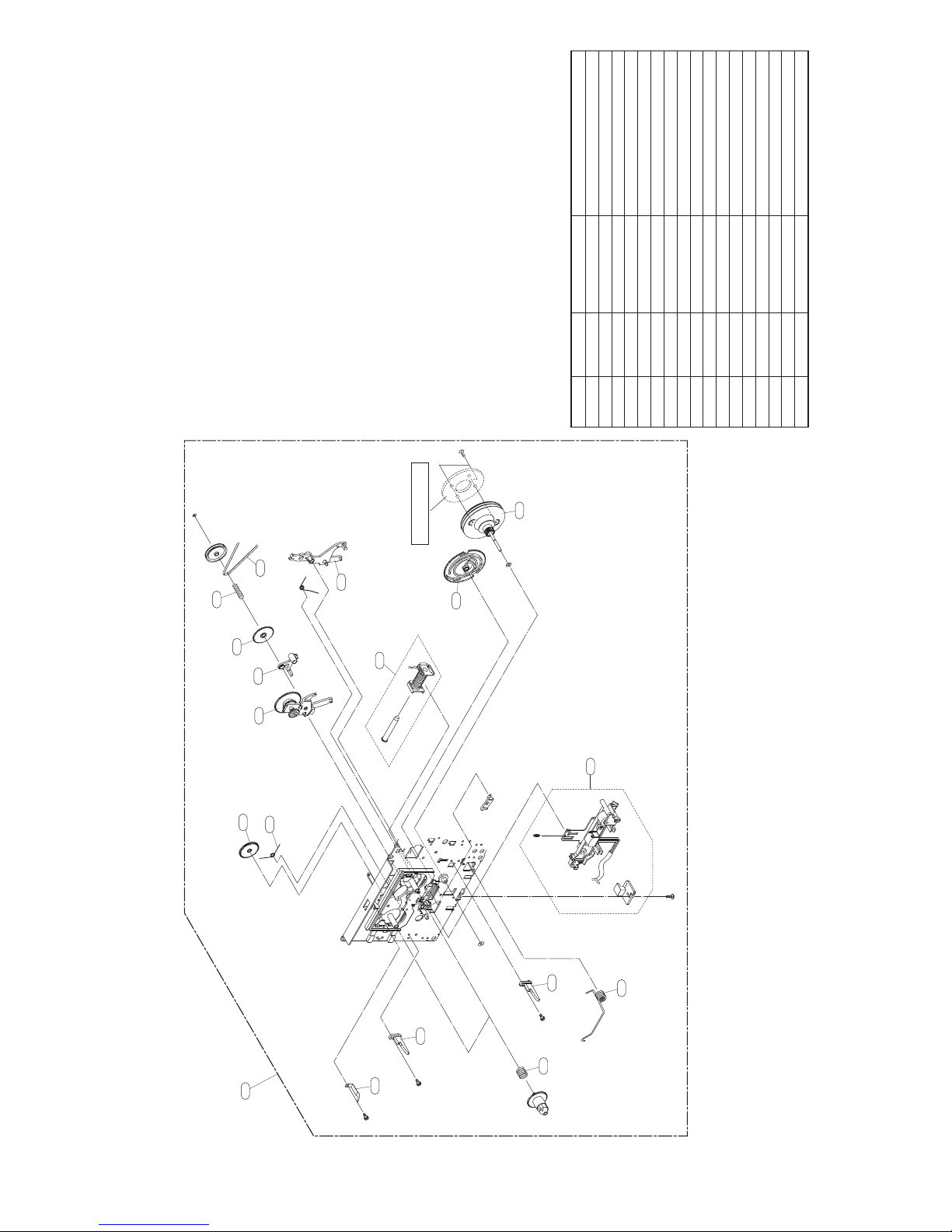
RING FW MAYBE ADDED
FOR WOW FLUTTER WHEN NECESSARY
003 6768R-PP03A Deck Mechanism Parts 33-160-4309 PIGEON PRESS CASSE
A00 EAZ35771801 Audio Deck CWP42FF601 07 year Double A/S+
A03 6768RZHP02C Deck Mechanism Parts 50-093-41236 50-093-41236 pige
LOCA. NO. PART NO. DESCRIPTION SPECIFICATION
TAPE DECK (LEFT A/S DECK) PARTS LIST
024
011 6768R-SP01A Deck Mechanism Parts 01-081-4601 PIGEON SPRING CWL4
007 6768RZGP03A Deck Mechanism Parts 50-222-41226 PIGEON GEAR IDLER
008 6768R-SP01F Deck Mechanism Parts 01-082-4598 PIGEON SPRING CWL4
009 6768R-MP01C Deck Mechanism Parts 50-219-4014 PIGEON MOLD CWL44
013 6768RZSP02A Deck Mechanism Parts 01-082-4688 PIGEON SPRING
015 6768R-AP01A Deck Mechanism Parts 50-268-3016 PIGEON ARM CWL44
016 6768RZGP04B Deck Mechanism Parts 50-093-31582 50-093-31582 PIGE
017 6768R-AP01C Deck Mechanism Parts 50-239-4072 PIGEON ARM CWL44
018 6768R-GP01J Deck Mechanism Parts 50-222-4428 PIGEON GEAR CRL442
019 6768R-SP01P Deck Mechanism Parts 01-081-4678 PIGEON SPRING CRL4
020 6768R-BP01M Deck Mechanism Parts 02-083-4276 02-083-4276 PIGEON
022 6768RZVP03C Deck Mechanism Parts 50-093-4748 50-093-4748 PIGEON
023 6768RZGP05A Deck Mechanism Parts 50-221-31320 PIGEON GEAR ASSY
024 6768RZJP02D Deck Mechanism Parts 50-093-41586 50-093-41586 PIGE
020
019
018
017
016
007
008
015
023
022
A03
009
013
2-7 2-8
A00
2-2. TAPE DECK MECHANISM (A/S & A/S : LEFT A/S DECK)
009
011
003
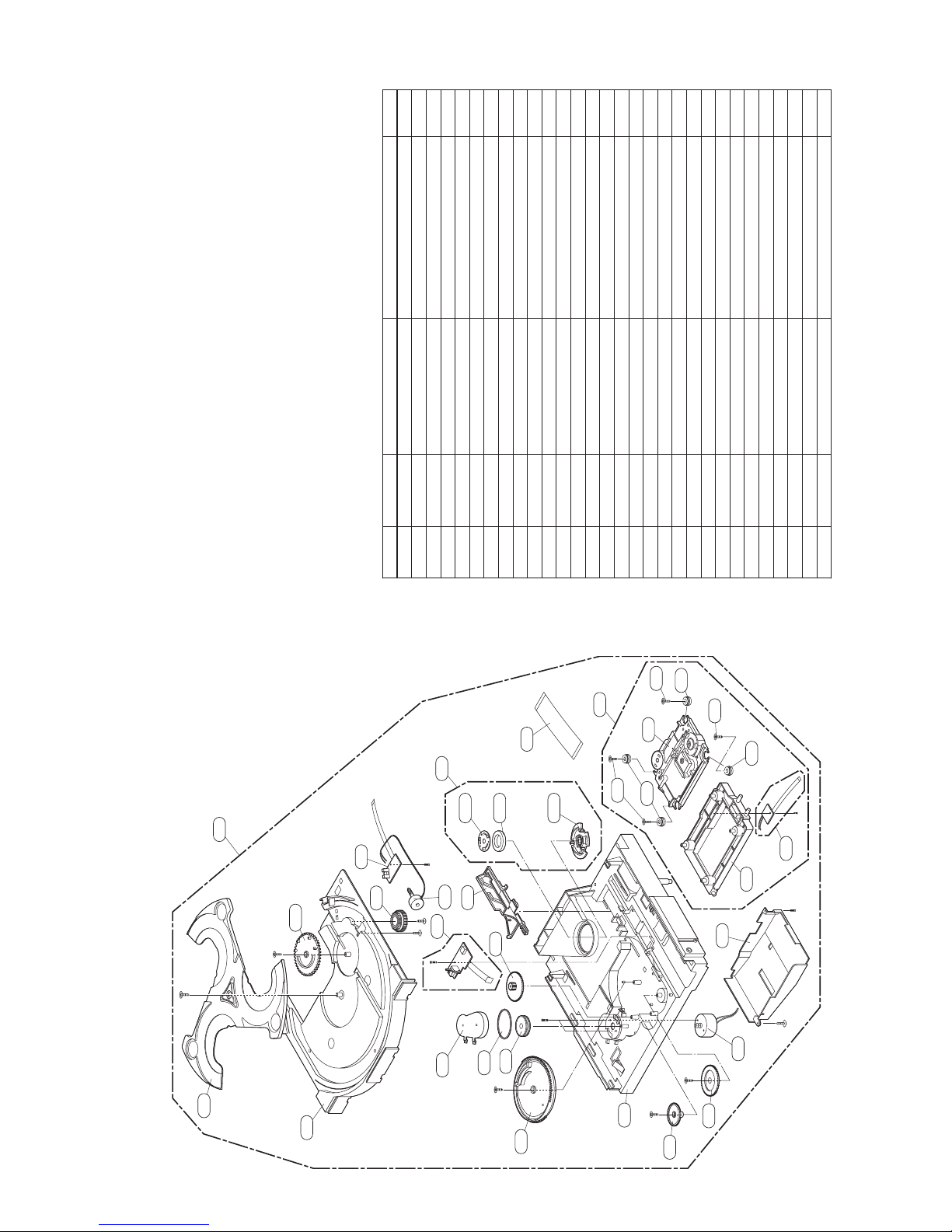
NSP : Not Service Part
LOCA. NO. PART NO. DESCRIPTION SPECIFICATION REMARK
A26 AFP70034802 Mechanism Assembly DVM-H1713 LG 3- DVD Short Dept NSP
A01 AAN70062601 Base Assembly DVM-H1713 IM TRVS
A02 4861RB0002C Clamp Assembly HOME DVM-H1573 CLAMP UPPER ASS
010 6850R-JW16B Cable,FFC 1.0-23-160-E-5x10x5x10-0.035x0
012 MCQ41263801 Damper MOLD BUTYL RUBBER DECK/MECHA D
035 EBR58632901 PCB Assembly,Deck DVM-H1713 DVM-H1713 3 changer
137 EAZ60002301 Pick Up Assembly CMS-S79RFVC1 CMS-S79RFVC1 IM 3
151 MJS41755901 Tray MOLD ABS XR-401 DECK/MECHA Dis
153 MDT41756101 Gear MOLD POM KEPITAL F20-03 DECK/M
153A MDT41756201 Gear MOLD POM KEPITAL F20-03 DECK/M
155 EAU48897301 Motor Assembly,DC RF-500TB AUDIO cdm-h1703 - MA
156 EBR60797401 PCB Assembly,Deck 3 CHANGER CDM-H1713 DVM-H1713
159 MJS57233701 Tray MOLD ABS HF-380 DECK/MECHA DVM
162 4400R-0012A Belt MOLD RUBBER DECK/MECHA MAIN C
163 4470R-0190A Gear MOLD POM DECK/MECHA PULLEY CD
164 4470RB0003A Gear MOLD POM HOME LOADING (CDM-H15
165 EBR48757901 PCB Assembly CDM-H1703 main -
166 4470RB0007A Gear MOLD POM HOME PU DOWN (CDM-H15
167 4470RB0006A Gear MOLD POM HOME PU UP (CDM-H1503
169A MGJ38556601 Plate PRESS SECC 0.8 dp-13 PRESS upp
169B RAB30611501 Magnet,Ferrite FERRITE 50G
169C MBU39672101 Clamp MOLD POM F20-03 DECK/MECHA DVM
170 MCK41756701 Cover MOLD ABS HF-380 DECK/MECHA bel
172 MAM57233502 Base MOLD ABS HF-380 DVM-H1713 MOLD
173 MEA41756501 Guide MOLD LUMAX GN-5006FC DECK/MECH
175 EAU48897601 Motor Assembly,DC RF-300EA AUDIO cmd-h1703 Loadi
177 MDT57234001 Gear MOLD POM KEPITAL F20-03 DECK/M
180 MDQ57233801 Frame MOLD LUMAX GN-5006FC DVM-H1713
181 MCK57621801 Cover MOLD ABS HF380 DECK/MECHA Dust
430 FAB30124101 Screw,Taptite 1szzr-0064 PWH + B 2.6MM 7MM S
151
A26
153A
159
156
153
A02
165
155
170
169A
173
162
169B
164
163
177
010
169C
A01
430
172
137
012
430
167
012
166
430
2-9 2-10
012
035
180
181
175
3. MECHANISM DECK EXPLODED VIEW (DVM-H1713)
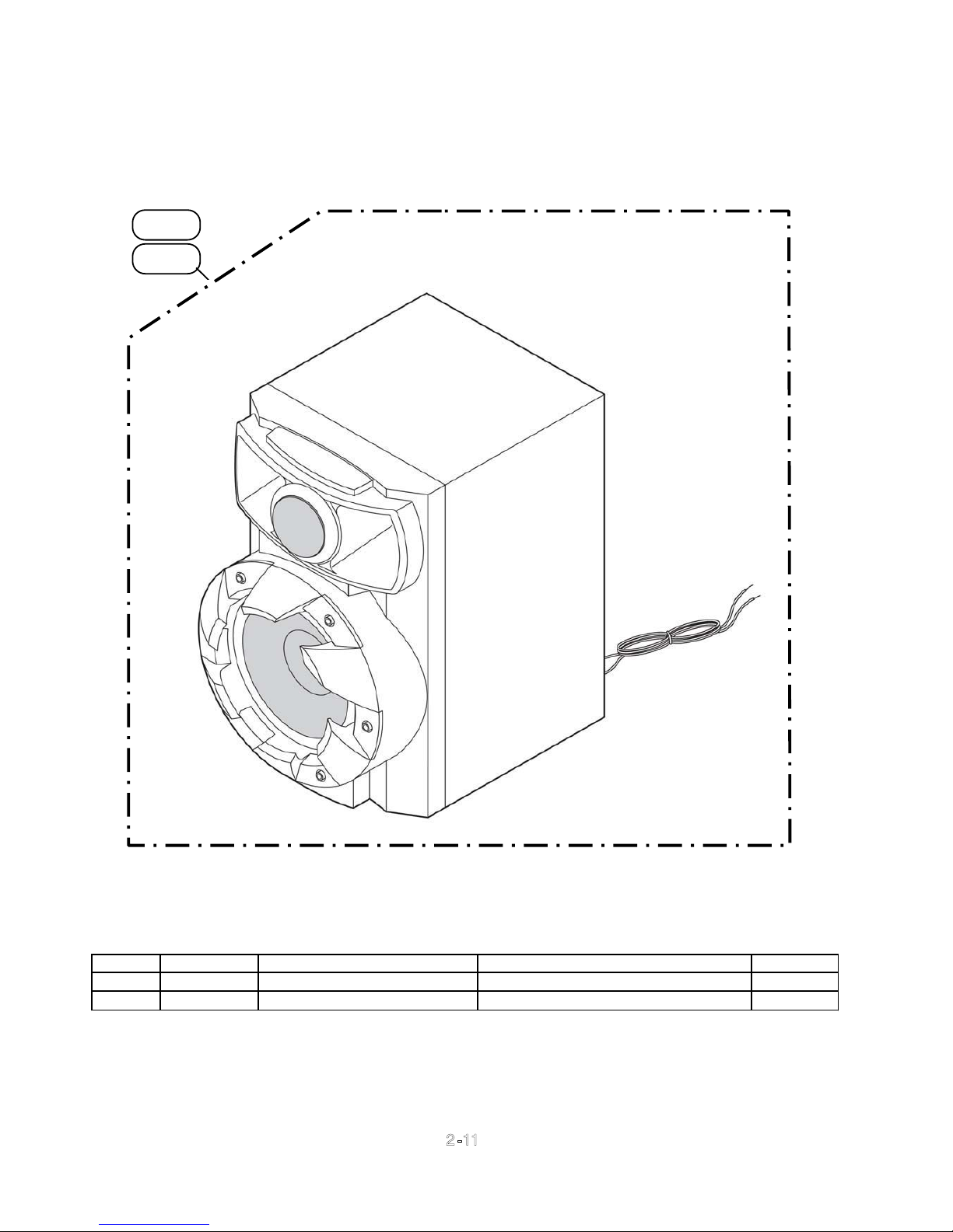
4. SPEAKER SECTION
(1) FRONT SPEAKER
A60L
A60R
LOCA. NO PART NO. DESCRIPTION SPECIFICATION REMARKS
A60L
A60R
EAB61030301 Speaker Assembly MCS404 049-01368-07 EAW MCS404
EAB61030201 MCS404F 049-01368-07 EAW MCS40
Speaker Assembly
2-11
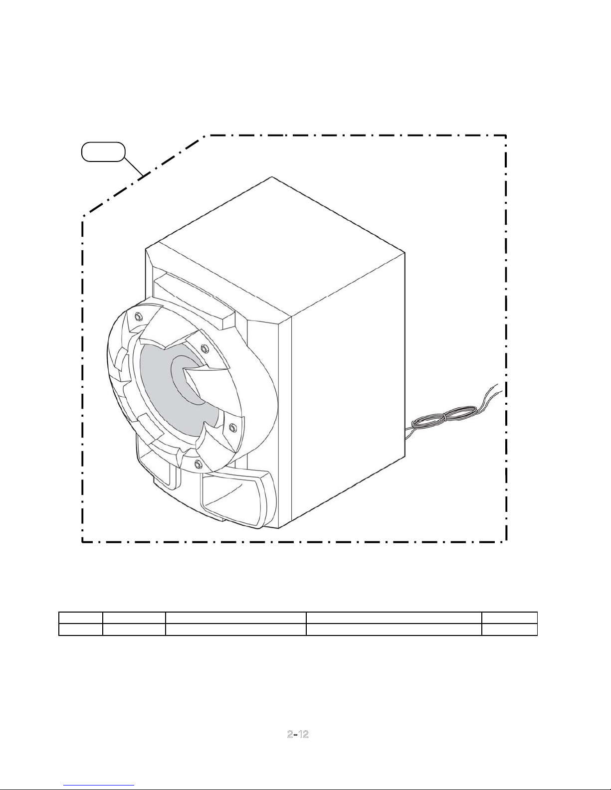
(2) PASSIVE SUBWOOFER
A90
LOCA. NO PART NO. DESCRIPTION SPECIFICATION REMARKS
A90
EAB61030401 Speaker Assembly MCS404W 049-01368-07 EAW MCS40
2-12
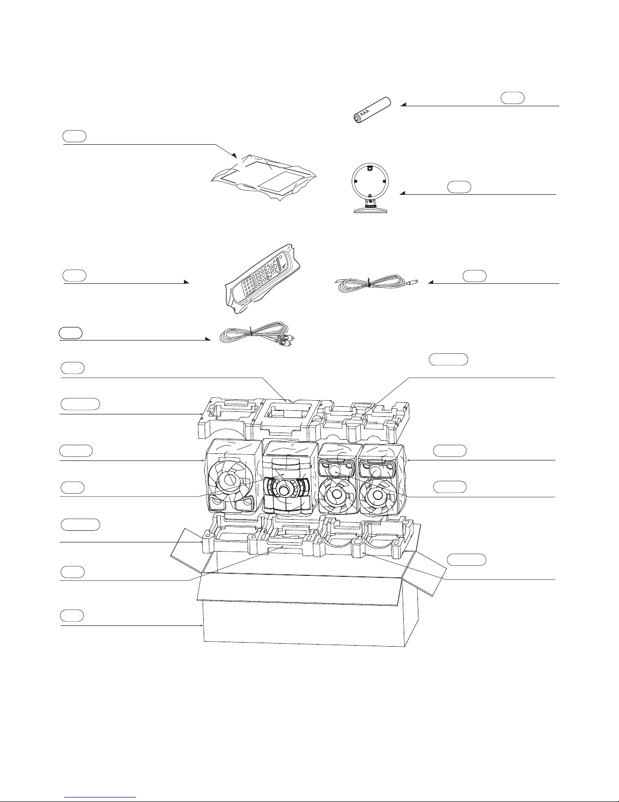
4. PACKING ACCESSORY SECTION
Instruction Ass'y
801
Remote Controller
900
811 RCA Cable, 1Pin(Black)
Antenna, Loop (AM)
824
Antenna, T (FM)
825
808
Battery
803 Packing, Main Set
803WT Packing, Woofer Top
804W Bag, Woofer 804F Bag, Front Speaker
804 Bag, Main Set
803WB Packing,
Woofer Bottom
803 Packing, Main Set
Box
802
803FT Packing,
Front Speaker Top
804F Bag, Front Speaker
803FB Packing,
Front Speaker Bottom
2-13
/
)
NOTES) If you want to purchase
Flash memory, you must order
"IC100A, IC503A"
NOTES) Warning
NOTES) Parts that are shaded are critical
NOTES) With respect to risk of fire or
NOTES) electricial shock.
/DXCN ( Latin America)
MODEL: X-RSM400DV
/LXCN ( ASEAN)
DXCNRI( Middle East
. PACKING & ACCESSORY SECTION
SALLOCA. NO. PART NO. DESCRIPTION SPECIFICATION REMARKS
801 AFN37125930 Manual Assembly,Owners HOME MDT404-A0.DPERPPK LG DXCN
802 MAY62411401 Box,Master BOX DW2 1141 414 442 3 COLOR M DXCN
803 MFZ47047395 Packing CUTTING EPS HOME THEATER MDT40
803WT MFZ61796892 Packing WOOF_TOP
803WB MFZ61796893
803FT MFZ61796894
803FB MFZ61796895
804 MAF37454613 Bag CUTTING EPE 630 600 0.5 EPE+HD
804W MAF61968002
804F MAF61968001
808 EAC42053701 Primary Cell Battery,Carbon Zi R03G(1EA Packing) R03 1.5V 0AH NSP
811 6850R-PAA8H Cable,Assembly 061104 RCA PLUG(3.2) RCA PLUG(
824 EAA56672101 Antenna,Loop SN080113AM SINGLE 4DB 10UH HW
825 5010R-T001D Antenna,T T13021F-2 SINGLE 0DB 0OHM 0 1.
Packing
Packing
Packing
Bag
Bag
WOOF_BOT
FRONT_TOP
FRONT_BOT
WOOF
FRONT
. REMOTE CONTROLLER
SALLOCA. NO. PART NO. DESCRIPTION SPECIFICATION REMARKS
900 AKB72913811 Remote Controller Assembly CB1 MDT404 MINI DVD Pioneer
CONTRAST TABLE
X-RSM400DV/DXCN, X-RSM400DV/DXCNRI and X-RSM400DV/LXCN are constructed the same except
for the following:
Ma rk No .
Symbol and Description
801 Manual Assembly, Owners AFN3 7125930 AFN37125932 AFN37125931
802 Box,Mas ter
X-RSM400DV/DXCN X-RS M400 DV/DXCNRI X-RS M400DV/LXCN Remark
MAY62411401
MAY62411405 MAY62411404
2-14

2-12
 Loading...