

Page 1

AUDIO/VIDEO MULTI-CHANNEL
RECEIVER
VSX-D814
VSX-D914
Operating Instructions
Page 2
Thank you for buying this Pioneer product.
Please read through these operating instructions
so you will know how to operate your model
properly. After you have finished reading the
instructions, put them away in a safe place for future
reference.
CAUTION – PREVENT ELECTRIC SHOCK DO
NOT USE THIS (POLARIZED) PLUG
WITH AN EXTENSION CORD.
RECEPTACLE OR OTHER OUTLET
UNLESS THE BLADES CAN BE
FULLY INSERTED TO PREVENT
BLADE EXPOSURE.
If the socket outlets on the associated equipment
are not suitable for the plug supplied with the
product, the plug must be removed and appropriate
one fitted. Replacement and mounting of an AC plug
on the power supply cord of this unit should be
perfomed only by qualified service personnel. The
cut-off plug must be disposed of as an electrical
shock hazard could exist if connected to a socket
outlet.
D3-4-2-2-1a_En
WARNING – TO PREVENT FIRE OR SHOCK
HAZARD, DO NOT EXPOSE THIS
APPLIANCE TO RAIN OR MOISTURE.
D1-4-2-1_En
ATTENTION –
WARNING: Handling the cord on this product or
cords associated with accessories sold with the
product will expose you to lead, a chemical known to
the State of California and other governmental
entities to cause cancer and birth defects or other
POUR PREVENIR LES CHOCS
ELECTRIQUES NE PAS UTILISER
CETTE FICHE POLARISEE AVEC UN
PROLONGATEUR UNE PRISE DE
COURANT OU UNE AUTRE SORTIE
DE COURANT, SAUF SI LES LAMES
PEUVENT ETRE INSEREES A FOND
SANS EN LAISSER AUCUNE PARTIE
A DECOUVVERT.
D2-4-4-1_EF
reproductive harm.
Wash hands after handling
D36-P4_En
IMPORTANT NOTICE – THE SERIAL NUMBER FOR THIS EQUIPMENT IS LOCATED IN THE REAR.
PLEASE WRITE THIS SERIAL NUMBER ON YOUR ENCLOSED WARRANTY CARD AND
KEEP IN A SECURE AREA. THIS IS FOR YOUR SECURITY.
D1-4-2-6-1_En
NOTE: This equipment has been tested and found to comply with the limits for a Class B digital device, pursuant to
Part 15 of the FCC Rules. These limits are designed to provide reasonable protection against harmful interference in
a residential installation. This equipment generates, uses, and can radiate radio frequency energy and, if not
installed and used in accordance with the instructions, may cause harmful interference to radio communications.
However, there is no guarantee that interference will not occur in a particular installation. If this equipment does
cause harmful interference to radio or television reception, which can be determined by turning the equipment off
and on, the user is encouraged to try to correct the interference by one or more of the following measures:
– Reorient or relocate the receiving antenna.
– Increase the separation between the equipment and receiver.
– Connect the equipment into an outlet on a circuit different from that to which the receiver is connected.
– Consult the dealer or an experienced radio/TV technician for help.
D8-10-1-2_En
This Class B digital apparatus complies with Canadian ICES-003.
Cet appareil numérique de la Classe B est conforme à la norme NMB-003 du Canada.
D8-10-1-3_EF
Information to User
Alteration or modifications carried out without appropriate authorization may invalidate the user’s right to operate
the equipment.
D8-10-2_En
CAUTION: This product satisfies FCC regulations when shielded cables and connectors are used to connect the
unit to other equipment. To prevent electromagnetic interference with electric appliances such as radios and
televisions, use shielded cables and connectors for connections.
Manufactured under license from Dolby
For U.S. and Australia Model
D8-10-3a_En
Laboratories. "Dolby", "Pro Logic",
"Surround EX", and the double-D symbol
are trademarks of Dolby Laboratories.
"DTS" ,"DTS-ES Extended Surround" and
"Neo:6" are trademarks of Digital Theater
Systems, Inc.
C67-7-3_En
Page 3
The lightning flash with arrowhead, within
an equilateral triangle, is intended to alert
the user to the presence of uninsulated
"dangerous voltage" within the product's
enclosure that may be of sufficient
magnitude to constitute a risk of electric
shock to persons.
CAUTION
RISK OF ELECTRIC SHOCK
DO NOT OPEN
CAUTION:
TO PREVENT THE RISK OF ELECTRIC
SHOCK, DO NOT REMOVE COVER (OR
BACK). NO USER-SERVICEABLE PARTS
INSIDE. REFER SERVICING TO QUALIFIED
SERVICE PERSONNEL.
The exclamation point within an equilateral
triangle is intended to alert the user to the
presence of important operating and
maintenance (servicing) instructions in the
literature accompanying the appliance.
D1-4-2-3_En
READ INSTRUCTIONS — All the safety and
operating instructions should be read before the
product is operated.
RETAIN INSTRUCTIONS — The safety and
operating instructions should be retained for
future reference.
HEED WARNINGS — All warnings on the product
and in the operating instructions should be
adhered to.
FOLLOW INSTRUCTIONS — All operating and use
instructions should be followed.
CLEANING — The product should be cleaned only
with a polishing cloth or a soft dry cloth. Never
clean with furniture wax, benzine, insecticides
or other volatile liquids since they may corrode
the cabinet.
ATTA CHMENTS — Do not use attachments not
recommended by the product manufacturer as
they may cause hazards.
WATER AND MOISTURE — Do not use this
product near water — for example, near a
bathtub, wash bowl, kitchen sink, or laundry
tub; in a wet basement; or near a swimming
pool; and the like.
ACCESSORIES — Do not place this product on an
unstable cart, stand, tripod, bracket, or table.
The product may fall, causing serious injury to a
child or adult, and serious damage to the
product. Use only with a cart, stand, tripod,
bracket, or table recommended by the
manufacturer, or sold with the product. Any
mounting of the product should follow the
manufacturer’s instructions, and should use a
mounting accessory recommended by the
manufacturer.
CART — A product and cart combination should be
moved with care. Quick stops, excessive force,
and uneven surfaces may cause the product
and cart combination to overturn.
VENTILATION — Slots and openings in the cabinet
are provided for ventilation and to ensure
reliable operation of the product and to protect
it from overheating, and these openings must
not be blocked or covered. The openings should
never be blocked by placing the product on a
bed, sofa, rug, or other similar surface. This
product should not be placed in a built-in
installation such as a bookcase or rack unless
proper ventilation is provided or the
manufacturer’s instructions have been adhered
to.
POWER SOURCES — This product should be
operated only from the type of power source
indicated on the marking label. If you are not
sure of the type of power supply to your home,
consult your product dealer or local power
company.
LOCATION – The appliance should be installed in a
stable location.
NONUSE PERIODS – The power cord of the
appliance should be unplugged from the outlet
when left un-used for a long period of time.
GROUNDING OR POLARIZATION
• If this product is equipped with a polarized
alternating current line plug (a plug having one
blade wider than the other), it will fit into the
outlet only one way. This is a safety feature. If
you are unable to insert the plug fully into the
outlet, try reversing the plug. If the plug should
still fail to fit, contact your electrician to replace
your obsolete outlet. Do not defeat the safety
purpose of the polarized plug.
• If this product is equipped with a three-wire
grounding type plug, a plug having a third
(grounding) pin, it will only fit into a grounding
type power outlet. This is a safety feature. If you
are unable to insert the plug into the outlet,
contact your electrician to replace your obsolete
outlet. Do not defeat the safety purpose of the
grounding type plug.
POWER-CORD PROTECTION — Power-supply
cords should be routed so that they are not likely
to be walked on or pinched by items placed
upon or against them, paying particular
attention to cords at plugs, convenience
receptacles, and the point where they exit from
the product.
OUTDOOR ANTENNA GROUNDING — If an
outside antenna or cable system is connected to
the product, be sure the antenna or cable
system is grounded so as to provide some
protection against voltage surges and built-up
static charges. Article 810 of the National
Electrical Code, ANSI/NFPA 70, provides
information with regard to proper grounding of
the mast and supporting structure, grounding of
the lead-in wire to an antenna discharge unit,
size of grounding conductors, location of
antenna-discharge unit, connection to
grounding electrodes, and requirements for the
grounding electrode. See Figure A.
LIGHTNING — For added protection for this
product during a lightning storm, or when it is
left unattended and unused for long periods of
time, unplug it from the wall outlet and
disconnect the antenna or cable system. This
will prevent damage to the product due to
lightning and power-line surges.
POWER LINES — An outside antenna system
should not be located in the vicinity of overhead
power lines or other electric light or power
circuits, or where it can fall into such power
lines or circuits. When installing an outside
antenna system, extreme care should be taken
to keep from touching such power lines or
circuits as contact with them might be fatal.
OVERLOADING — Do not overload wall outlets,
extension cords, or integral convenience
receptacles as this can result in a risk of fire or
electric shock.
ELECTRIC
SERVICE
EQUIPMENT
Fig. A
OBJECT AND LIQUID ENTRY — Never push
objects of any kind into this product through
openings as they may touch dangerous voltage
points or short-out parts that could result in a
fire or electric shock. Never spill liquid of any
kind on the product.
SERVICING — Do not attempt to service this
product yourself as opening or removing covers
may expose you to dangerous voltage or other
hazards. Refer all servicing to qualified service
personnel.
DAMAGE REQUIRING SERVICE — Unplug this
product from the wall outlet and refer servicing
to qualified service personnel under the
following conditions:
• When the power-supply cord or plug is
damaged.
• If liquid has been spilled, or objects have fallen
into the product.
• If the product has been exposed to rain or water.
• If the product does not operate normally by
following the operating instructions. Adjust only
those controls that are covered by the operating
instructions as an improper adjustment of other
controls may result in damage and will often
require extensive work by a qualified technician
to restore the product to its normal operation.
• If the product has been dropped or damaged in
any way.
• When the product exhibits a distinct change in
performance — this indicates a need for service.
REPLACEMENT PARTS — When replacement parts
are required, be sure the service technician has
used replacement parts specified by the
manufacturer or have the same characteristics
as the original part. Unauthorized substitutions
may result in fire, electric shock, or other
hazards.
SAFETY CHECK — Upon completion of any service
or repairs to this product, ask the service
technician to perform safety checks to
determine that the product is in proper
operating condition.
WALL OR CEILING MOUNTING — The product
should not be mounted to a wall or ceiling.
HEAT — The product should be situated away from
heat sources such as radiators, heat registers,
stoves, or other products (including amplifiers)
that produce heat.
ANTENNA
LEAD IN
GROUND
CLAMP
WIRE
ANTENNA
DISCHARGE UNIT
(NEC SECTION 810-20)
GROUNDING CONDUCTORS
(NEC SECTION 810-21)
GROUND CLAMPS
POWER SERVICE GROUNDING
ELECTRODE SYSTEM
(NEC ART 250, PART H)
NEC — NATIONAL ELECTRICAL CODE
D1-4-2-2_En
Page 4

Contents
01 Before you start
Checking what’s in the box. . . . . . . . . . . . . . 6
Installing the receiver . . . . . . . . . . . . . . . . . . 6
Making cable connections . . . . . . . . . . . . . . 6
Loading the batteries. . . . . . . . . . . . . . . . . . . 6
Operating range of remote control unit. . . . 7
02 5 minute guide
Introduction to home theater . . . . . . . . . . . . 8
Listening to Surround Sound . . . . . . . . . . . . 9
Using the Quick Setup . . . . . . . . . . . . . . . . 12
03 Quick surround sound setup
Automatically calibrating your listening
area (MCACC) . . . . . . . . . . . . . . . . . . . . . . . 14
04 Connecting up
Audio/Video cords . . . . . . . . . . . . . . . . . . . . 16
S-video cables . . . . . . . . . . . . . . . . . . . . . . . 16
Component video cords . . . . . . . . . . . . . . . 16
Digital audio coaxial cords/
Optical cables . . . . . . . . . . . . . . . . . . . . . . . 16
Connecting digital components . . . . . . . . . 17
Connecting audio components . . . . . . . . . 18
Connecting DVD 5.1 channel
components . . . . . . . . . . . . . . . . . . . . . . . . . 18
Connecting video components. . . . . . . . . . 19
Connecting to the front panel
video terminal . . . . . . . . . . . . . . . . . . . . . . 19
Connecting antennas . . . . . . . . . . . . . . . . . 20
FM wire antenna . . . . . . . . . . . . . . . . . . . . 20
AM loop antenna. . . . . . . . . . . . . . . . . . . . 20
Using external antennas . . . . . . . . . . . . . 20
Connecting the speakers . . . . . . . . . . . . . . 21
Speaker terminals . . . . . . . . . . . . . . . . . . . 22
A and B speaker systems . . . . . . . . . . . . . 22
Hints on speaker placement . . . . . . . . . . 22
Connecting additional amplifiers . . . . . . . . 24
AC outlet . . . . . . . . . . . . . . . . . . . . . . . . . . . . 25
Operating other Pioneer components . . . . 25
Using this receiver with a Pioneer
plasma display . . . . . . . . . . . . . . . . . . . . . . . 26
05 Controls and displays
Front panel . . . . . . . . . . . . . . . . . . . . . . . . . . 27
Display . . . . . . . . . . . . . . . . . . . . . . . . . . . . . 29
Remote control. . . . . . . . . . . . . . . . . . . . . . . 31
06 Listening to your system
Listening in surround sound. . . . . . . . . . . . 35
Using the Advanced surround effects. . . 35
Listening in stereo . . . . . . . . . . . . . . . . . . . . 36
Choosing the input signal . . . . . . . . . . . . . . 37
Using the Surround Back Channel
(SB CH) . . . . . . . . . . . . . . . . . . . . . . . . . . . . . 38
Using the Virtual Surround Back
mode (VSB). . . . . . . . . . . . . . . . . . . . . . . . . . 39
Using Loudness and Midnight listening . . 40
Using the tone controls . . . . . . . . . . . . . . . . 40
Playing other sources . . . . . . . . . . . . . . . . . 40
Selecting the multi-channel analog
inputs . . . . . . . . . . . . . . . . . . . . . . . . . . . . . . 41
Using the sleep timer . . . . . . . . . . . . . . . . . 41
07 Setting up the receiver
Choosing your receiver setup . . . . . . . . . . . 42
Speaker setting . . . . . . . . . . . . . . . . . . . . . 43
Surround back speaker setting . . . . . . . . 44
Subwoofer setting . . . . . . . . . . . . . . . . . . . 44
Crossover frequency setting. . . . . . . . . . . 44
LFE attenuator setting. . . . . . . . . . . . . . . . 45
Front left speaker distance setting . . . . . 45
Center speaker distance setting . . . . . . . 45
Front right speaker distance setting . . . . 46
Surround right speaker distance
setting. . . . . . . . . . . . . . . . . . . . . . . . . . . . . 46
Surround back speaker distance
setting. . . . . . . . . . . . . . . . . . . . . . . . . . . . . 46
Page 5

Surround left speaker distance setting . . 46
Subwoofer distance setting . . . . . . . . . . . 46
Dynamic range control setting. . . . . . . . . 47
Dual mono setting . . . . . . . . . . . . . . . . . . . 47
Component video input settings . . . . . . . 47
Digital input settings . . . . . . . . . . . . . . . . . 47
SR+ control for Pioneer plasma
displays. . . . . . . . . . . . . . . . . . . . . . . . . . . . 48
Manually calibrating your listening
area (MCACC). . . . . . . . . . . . . . . . . . . . . . . . 49
Setting separate channel levels for
listening modes . . . . . . . . . . . . . . . . . . . . . . 50
Using the SR+ mode with a Pioneer
plasma display . . . . . . . . . . . . . . . . . . . . . . . 51
08 Using the tuner
Listening to the radio . . . . . . . . . . . . . . . . . . 53
Improving FM stereo sound . . . . . . . . . . . 53
Tuning directly to a station . . . . . . . . . . . . 53
Saving station presets . . . . . . . . . . . . . . . . . 54
Naming station presets. . . . . . . . . . . . . . . 54
Listening to station presets. . . . . . . . . . . . 55
09 Making recordings
Making an audio or a video recording . . . . 56
10 Controlling the rest of your
system
Setting the remote to control other
components . . . . . . . . . . . . . . . . . . . . . . . . . 57
Selecting preset codes directly . . . . . . . . . . 57
Programming signals from other
remote controls. . . . . . . . . . . . . . . . . . . . . . . 58
Erasing one of the remote control
button settings . . . . . . . . . . . . . . . . . . . . . . . 59
Erasing all of the remote control
presets . . . . . . . . . . . . . . . . . . . . . . . . . . . . . . 60
Direct function . . . . . . . . . . . . . . . . . . . . . . . 60
Confirming preset codes . . . . . . . . . . . . . . . 60
Controls for TVs. . . . . . . . . . . . . . . . . . . . . . . 61
Controls for other components . . . . . . . . . . 62
11 Additional information
Troubleshooting . . . . . . . . . . . . . . . . . . . . . . 65
Resetting the main unit . . . . . . . . . . . . . . . . 67
Switching the speaker impedance . . . . . . . 67
Specifications . . . . . . . . . . . . . . . . . . . . . . . . 68
Cleaning the unit . . . . . . . . . . . . . . . . . . . . . 69
Page 6
01
Before you start
Chapter 1:
Before you start
Checking what’s in the box
Please check that you've received the
following supplied accessories:
• AM loop antenna
• FM wire antenna
• AA/LR6 dry cell batteries x2
• Remote control
• These operating instructions
•
Warranty Card
VSX-D914 model only:
• Microphone
• Microphone stand
Installing the receiver
Please note the following points:
• Do not place objects directly on top of this
unit. This prevents proper heat dispersal.
• When installing on a rack, shelf, etc., be
sure to leave more than 8 inches (20 cm.)
of space above the receiver.
Making cable connections
Make sure not to bend the cables over the top
of this unit (as shown in the illustration). If this
happens, the magnetic field produced by the
transformers in this unit may cause a
humming noise from the speakers.
Loading the batteries
Incorrect use of batteries may result in such
hazards as leakage and bursting. Observe the
following precautions:
• Never use new and old batteries together.
• Insert the plus and minus sides of the
batteries properly according to the marks
in the battery case.
• Batteries with the same shape may have
different voltages. Do not use different
batteries together.
6
En
Page 7
Before you start
• When disposing of used batteries, please
comply with governmental regulations or
environmental public instruction’s rules
that apply in your country or area.
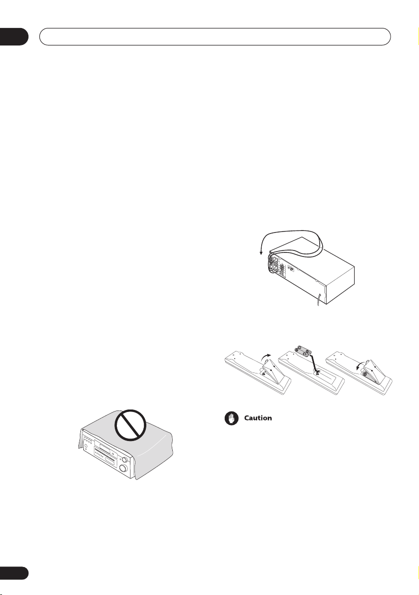
Operating range of remote
control unit
The remote control may not work properly if:
• There are obstacles between the remote
control and the receiver's remote sensor.
• Direct sunlight or fluorescent light is
shining onto the remote sensor.
• The receiver is located near a device that
is emitting infrared rays.
• The receiver is operated simultaneously
with another infrared remote control unit.
01
30
30
23ft (7m)
7
En
Page 8

02
5 minute guide
Chapter 2:
5 minute guide
Introduction to home theater
You are probably used to using stereo equipment to listen to music, but may not be used to
home theater systems that give you many more options (such as surround sound) when
listening to soundtracks.
Home theater refers to the use of multiple audio tracks to create a surround sound effect,
making you feel like you're in the middle of the action or concert. The surround sound you get
from a home theater system depends not only on the speakers you have set up in your room, but
also on the source and the sound settings of the receiver.
DVD-Video has become the basic source material for home theater due to its size, quality, and
ease of use. Depending on the DVD, you can have up to seven different audio tracks coming
from one disc, all of them being sent to different speakers in your system. This is what creates
a surround sound effect and gives you the feeling of ‘being there’.
This receiver will automatically decode Dolby Digital, DTS, or Dolby Surround DVD-Video discs,
according to your speaker setup. In most cases, you won’t have to make changes for realistic
surround sound, but other possibilities (like listening to a CD with multi-channel surround
sound) are explained in
Listening to your system
on page 35.
8
En
Page 9
5 minute guide
A
Listening to Surround Sound
This receiver was designed with the easiest possible setup in mind, so with the following quick
setup guide, you should have your system hooked up for surround sound in no time at all. In
most cases, you can simply leave the receiver in the default settings.
Be sure to complete all connections before connecting this unit to the AC power source.
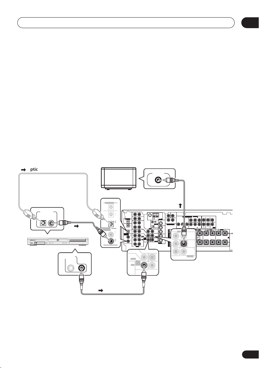
1 Hook up your DVD player.
For surround sound, you’ll want to hook up using a digital connection from the DVD player to
the receiver. You can do this with either a coaxial, or an optical connection (you don’t need to
connect both). If you hook up using an optical cable, you should refer to
on page 47 to assign the optical input to
DVD
.
Use a video cord to connect the video output on your DVD player to the receiver using the jacks
shown below.
2 Hook up your TV.
Use a video cord to connect your receiver to the TV using the jacks as shown below.
Digital input settings
02
Optical cable
DIGITAL OUT
STANDBY/ON
0
DVD player
TV
VIDEO IN
DIGITAL OUT
OPT
ASSIGNABLE
DIGITAL IN
OPT
2
(DVR/VCR)
OPT
1
(TV /
SA T)
COAX
2
(CD)
COAX
1
(DVD
/LD)
DIGITAL OUT
ASSIGNABLE
DIGITAL IN
(DVR/VCR)
AUX
IN
FM UNBAL
AM
Ω
75
LOOP
ANTENNA
CD
IN
OPT
OPT
OUT
2
IN
OPT
1
(TV/
IN
SAT)
COAX
2
IN
(CD)
COAX
1
OUT
(DVD
/LD)
IN
R
L
AUDIO
IN
DVD
/ LD
FRONT
D V D
5.1CH
INPUT
REC
IN
CD-R
/TAPE
/ MD
MONITOR OUT
OUT
CONTROL
DVR/
VCR
IN
VIDEO
IN
TV/
OUT
SAT
IN
DVD
MONITOR
/LD
OUT
FRONT
D V D
5.1CH
SUB
INPUT
REC
WOOFER
IN
CD-R
PREOUT
/ TAPE
/ MD
S-VIDEO
PLAY
Coaxial
cable
DVD PLAYER
Î
8
¡¢41
7
3
VIDEO OUT
S
Video cord
CEN-
SUB WOOFER
TER
COMPONENT VIDEO
MONITOR OUT
LR
SURROUND
DVD 5.1CH INPUT
BPRYPBPR
YP
OUT
DVR/
FRONT
RL R
VCR
S
VIDEO
IN
P
E
TV/
SAT
A
IN
A
K
DVD
/LD
E
IN
IN
R
S
ASSIGNABLE
LL
(
)
DVD/ LD
IN
¥
RR
(
)
TV / SAT
FRONT
IN
ø
SURROUND BACK
RL
OUT
SINGLE
SEE INSTRUCTION
MANUAL
MONITOR
OUT
SUB
WOOFER
PREOUT
SURROUND
BACK
CENTER
PREOUT
SURROUND
LR L
FRONTCENTER SURROUND
B
Video cord
9
En
Page 10
02
E
UNBAL
COMPONENT VIDEO
CEN-
R
SURROU
BA
INPUT
A
N
SW
subwoofer
surround
bac
r
5 minute guide
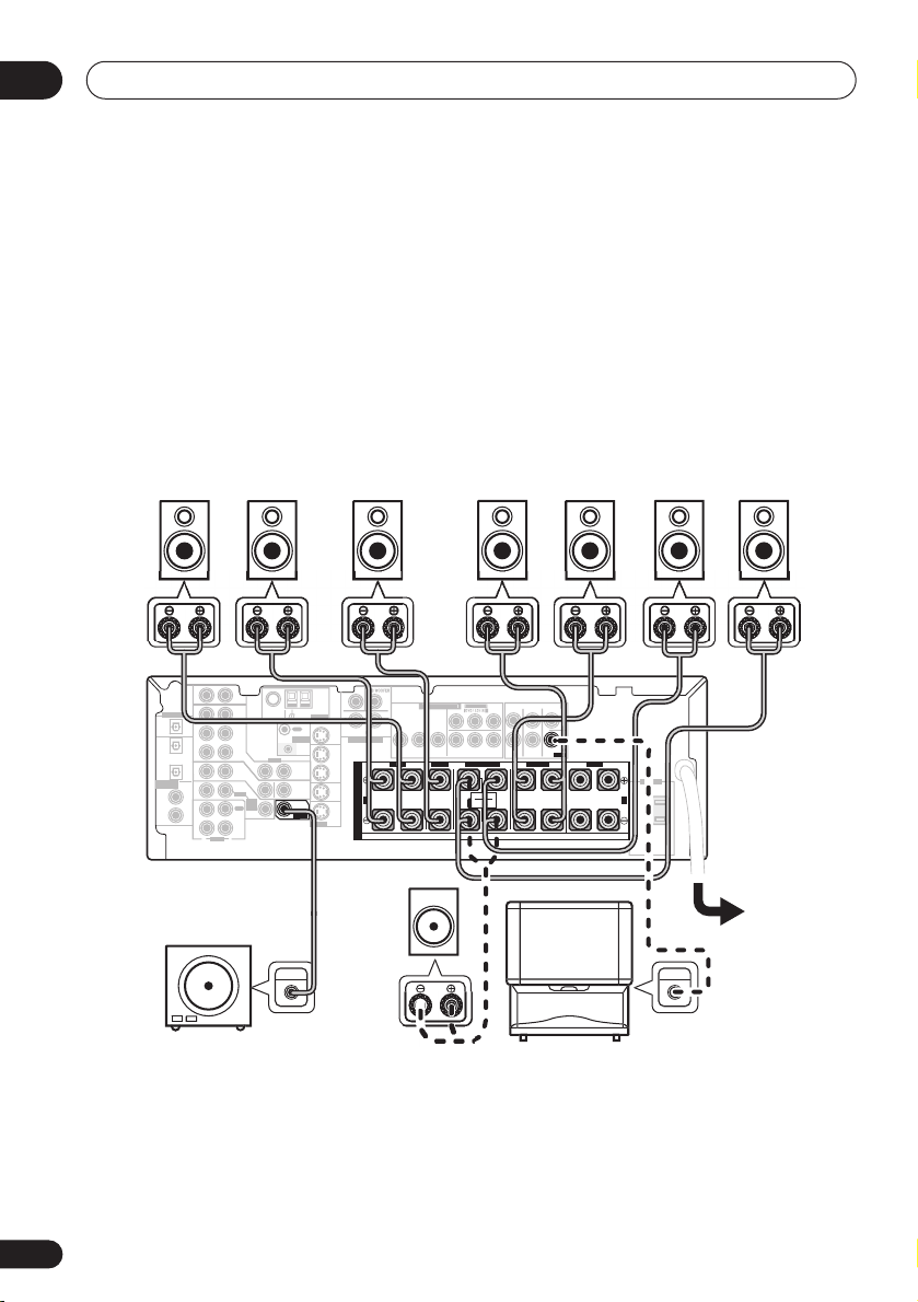
3 Connect your speakers.
A complete setup of eight speakers (including the subwoofer) is shown here but everyone’s
home setup will vary. Simply connect the speakers you have in the manner shown below. The
receiver will work with just two stereo speakers (the front speakers in the diagram) but using at
least three speakers is recommended, and a complete setup is best.
Make sure you connect the speaker on the right to the right terminal and the speaker on the left
to the left terminal. Also make sure the positive and negative (
match those on the speakers. You can use speakers with a nominal impedance between 6–16
(please see
impedance of less than 8
Switching the speaker impedance
Ω
).
on page 67 if you plan to use speakers with an
+/–
) terminals on the receiver
Ω
Front speakers
Center speaker
Surround speakers
LR C LSRS
DIGITAL OUT
IN
OPT
OPT
OUT
2
(DVR/VCR)
IN
OPT
1
(TV/
IN
SAT)
ASSIGNABLE
COAX
DIGITAL IN
2
IN
(CD)
COAX
1
OUT
(DVD
/LD)
IN
Powered
AUX
75
Ω
CD
DVR/
VCR
VIDEO
IN
TV/
SAT
IN
DVD
/LD
FRONT
D V D
5.1CH
INPUT
REC
IN
CD-R
/ TAPE
/ MD
PLAY
R
L
AUDIO
OUT
CONTROL
OUT
MONITOR
OUT
SUB
WOOFER
PREOUT
LOOP
IN
ANTENNA
MONITOR OUT
OUT
DVR/
VCR
TV/
SAT
DVD
/LD
S-VIDEO
Passive
TE
MONITOR OUT
LR
SURROUND
DVD 5.1CH INPUT
IN
IN
IN
BPR
YP
FRONT
RL R
S
P
E
A
A
K
E
R
S
ASSIGNABL
YPBP
R
RR
(
)
TV / SAT
FRONT
SURROUND
IN
ø
SURROUND BACK
RL
SINGLE
SEE INSTRUCTION
MANUAL
CENTER
PREOUT
LR L
Surround back speakers
SBL SBR
FRONTCENTER SURROUND
AC OUTLET
B
subwoofer
or single
k
speake
• If you’re not using a subwoofer, change the front speaker setting (see
TV
UDIO I
Speaker setting
page 43) to large.
• To use the speaker on your TV as the center speaker (
C
), connect the
CENTER PREOUT
on this unit to the audio input jack on your TV. In this case the center speaker shown is
unnecessary.
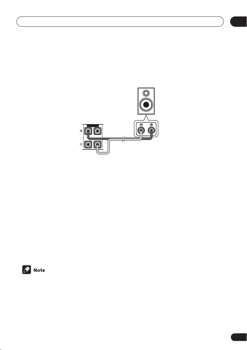
• If you are using only one surround back speaker, connect the positive wire to the right
channel (
+
) terminal, and the negative wire to the left channel (–) terminal (shown below).
on
jack
10
En
Page 11
5 minute guide
02
• If you select subwoofer (
SB SW
) in the
Surround back speaker setting
on page 44 you can
hook up a subwoofer instead of speakers to the surround back speaker terminals. Connect
the wires just as above (and as shown below), connecting the positive wire to the right
channel (
+
) terminal, and the negative wire to the left channel (–) terminal.
Surround back
speaker (or
subwoofer)
SURROUND BACK
RL
4 Plug in the receiver and switch it on, followed by your DVD player, your subwoofer
and the TV.
Make sure you’ve set the video input on your TV to this receiver. Check the manual that came
with the TV if you don’t know how to do this.
Also make sure that
is selected. If it isn’t, press
DVD/LD
is showing in the receiver’s display, indicating that the DVD input
DVD
on the remote control to set the receiver to the DVD input.
5 Press QUICK SETUP on the front panel to specify your speaker setup, room size and
listening position.
Use the
Setup
VSX-D914 model only
automatic MCACC setup in the
MULTI JOG
dial to select and
ENTER
to confirm your selection. See
on page 12 if you’re unsure about the settings.
– For a more complete surround sound setup, we recommend using the
Quick surround sound setup
Using the Quick
on page 14.
6 Play a DVD, and adjust the volume to your liking.
There are several other sound options you can select. See
for more on this. See also
Choosing your receiver setup
Listening to your system
on page 35
on page 42 for more setup options.
• Depending on your DVD player or source discs, you may only get digital 2 channel stereo
and analog sound. In this case, the listening mode must be set to
already be set—see
Listening in surround sound
on page 35 if you need to do this) if you
STANDARD
(it should
want multi-channel surround sound.
11
En
Page 12

02
5 minute guide
Using the Quick Setup
You can use the Quick Setup to get your
system up and running with just a few button
presses. The receiver automatically makes
the necessary settings after you have selected
your speaker setup, room size and listening
position.
If you want to make more specific settings,
refer to
Choosing your receiver setup
page 42.
Use the front panel controls for the steps
below.
VSX-D914 model only
– Note that you don’t
have to make these settings if you use the
automatic MCACC setup instead (in this
case, go straight to the
setup
on page 14).
SB CH
TONE
MODE
SPEAKERS
VIDEO INPUT
S-VIDEO VIDEO
L AUDIO R
Quick surround sound
ENTER
MULTI JOG
QUICK SETUP
MASTER VOLUME
on
MULTI JOG
UPDOWN
3 Use the MULTI JOG dial to choose your
speaker setup.
When a subwoofer was detected in step 2, you
can cycle between the following choices:
2.1ch 3.1ch
7.1ch
4.1ch
6.1ch 5.1ch
If a subwoofer wasn’t detected in step 2, you
can cycle between the following choices:
2.0ch 3.0ch
7.0ch
4.0ch
6.0ch 5.0ch
• Check the table below to find the speaker
setup that corresponds with your system.
12
En
1 If the receiver is off, press
STANDBY/ON to turn the power on.
2 Press QUICK SETUP.
SW DET
flashes in the display while the
receiver checks your setup for a subwoofer.
SW YES
or
SW NO
confirms the subwoofer
check, then the display prompts you to select
your speaker setup.
4 Press ENTER.
5 Use the MULTI JOG dial to choose your
room size.
Depending on the distance of your speakers
from the listening position, choose between
small, medium, or large (
S, M
or L), M being
an average-sized room.
Page 13

5 minute guide
6 Press ENTER.
7 Use the MULTI JOG dial to choose your
listening position.
You can cycle between the following choices:
FWD
MID
BACK
FWD
– If you are nearer to the front
speakers than the surround speakers
MID
– If you are equal distance from the
front and surround speakers
BACK
– If you are nearer to the surround
speakers than the front speakers
8 Press ENTER to confirm your setup.
The display shows the speaker setup, room
size and listening position that you have
selected.
02
13
En
Page 14
03
Quick surround sound setup
Chapter 3:
Quick surround sound setup
VSX-D914 model only
14
En
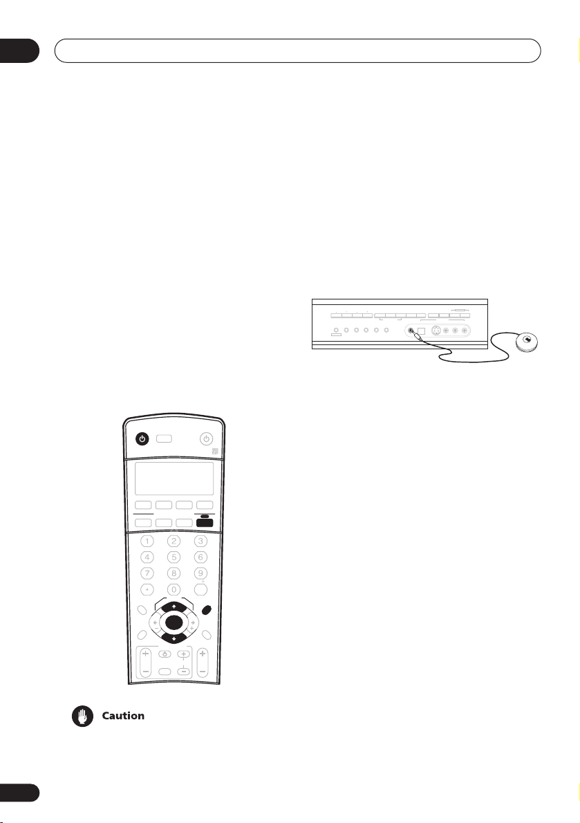
Automatically calibrating
your listening area (MCACC)
The Multi-Channel Acoustic Calibration
(MCACC) system measures the acoustic
characteristics of your listening area, taking
into account ambient noise, speaker size and
distance, and tests for both channel delay and
channel level. After you have set up the
microphone provided with your system, the
receiver uses the information from a series of
test tones to optimize the speaker settings
and equalization for your particular room.
INPUT
RECEIVER
DVD/LD TV/SAT DVR/VCR TV CONT
CD
INPUT ATT FL DIMMER SR
+
D.ACCESS
TOP MENU
ST ST
DTV MENU
T.EDIT
GUIDE
TV VOL
• These test tones can be loud, so take care
that there is no one in the room who will
be startled by the noise.
SELECT
MULTI CONTROL
CD-R/TAPE
10
SETUP
TUNE
ENTER
TUNE
TV CONTROL
INPUT
SELECT
SOURCE
TUNER RECEIVER
ENTER
CLASS
MENU
MCACC
BAND
RETURN
TV CH
VOL
DISC
SETUP
• Make sure the mic and speakers are not
moved during the MCACC setup.
1 Connect the microphone to the
MCACC SETUP MIC jack on the front panel.
ADVANCED
STEREO/
TUNING
STATION
MPX
TUNER EDIT
BAND
CLASS
MULTI JOG
SIGNAL
SURROUND
DIRECT
SELECT
STANDARD SPEAKERS
LISTENING MODE
MCACC
FL DIMMER
INPUT ATT
MULTI JOG
MIDNIGHT/
SB CH
LOUDNESS
MODE
TONE
QUICK SETUP
VIDEO INPUT
S-VIDEODIGITAL INSETUP MIC VIDEO
L AUDIO R
2 Place the microphone at your normal
listening position.
Place the mic about ear level at your normal
listening position using the supplied microphone stand on a table or chair.
Make sure there are no obstacles between the
speakers and the microphone.
3 If the receiver is off, press
STANDBY/ON to turn the power on.
4 If you have a subwoofer, turn it on.
5 Press RECEIVER.
6 Press MCACC SETUP.
Try to be as quiet as possible after pressing
MCACC SETUP
. The system outputs a series
of test tones to establish the ambient noise
level.
If the noise level is too high,
NOISY!
blinks in
the display for five seconds. To exit and check
the noise levels again, press
MCACC SETUP
(see the notes regarding ambient noise levels
below) or press
to
GO NEXT?
ENTER
when you’re prompted
The system now checks the microphone and
your speaker setup.
Page 15
Quick surround sound setup
03
If you see an
there may be a problem with your mic or the
speaker connections.
Turn off the power, and check the problem
indicated by the
then try the auto surround setup again.
•
ERR MIC
connection.
•
ERR Fch
connections.
•
ERR Sch
surround back speaker connections.
•
ERR SW
been switched on and volume on the
subwoofer is turned up.
7 Use and to select the speaker
system that corresponds to your setup.
Cycle between the following choices:
ERR
message in the display,
ERR
message (see below),
– Check the microphone
– Check the front speaker
– Check the surround or
– Make sure the subwoofer has
2.0ch 2.1ch* 3.1ch*3.0ch
7.1ch*
7.0ch
4.0ch
4.1ch*
6.1ch* 6.0ch 5.0ch5.1ch*
* Indicates a subwoofer is included in your
speaker setup
See the table on page 12 if you’re unsure
which speaker system to select.
8 If you selected a speaker system that
includes a subwoofer, press ENTER to
check the subwoofer output level.
If the subwoofer output level is too high/low,
SW.VOL.DWN/SW.VOL.UP
display for five seconds. To exit and check
your subwoofer output level, press
SETUP
(see the notes regarding noise levels
below) or simply press
prompted to
GO NEXT?
blinks in the
ENTER
MCACC
when you’re
9 Press ENTER to finish the auto
surround setup.
The system checks for speaker size, channel
delay and channel level. If you have
connected a subwoofer, it will check for
ambient noise once again.
When the auto surround setup is complete,
the volume level returns to normal and
COMPLETE
display. The MCACC indicator then lights to
show that MCACC setup is complete.
• If the room environment is not optimal for
• Some older TVs may interfere with the
• Using the MCACC system to set up your
• When the
• Depending on the characteristics of your
, then
RESUME
the auto surround setup (too much
ambient noise, echo off the walls, obstacles blocking the speakers from the
microphone) the final settings may be
incorrect. Check for household appliances (air conditioner, fridge, fan, etc.),
that may be affecting the environment
and switch them off if necessary.
operation of the mic. If this seems to be
happening, switch off the TV when doing
the auto surround setup.
speaker system overwrites any previous
settings you had for the
ADVANCED SURROUND
SURROUND
check the settings made with MCACC by
using
levels) or by going through the steps in
Choosing your receiver setup
to check other settings.
room, sometimes identical speakers with
cone sizes of around 5 inches (12cm) will
end up with different size settings. You
can correct the setting manually using
the receiver setup on page 42.
STANDARD
mode is selected, you can
CH SELECT
shows in the
STANDARD
modes.
or
ADVANCED
(to check channel
on page 42
or
15
En
Page 16
04
Connecting up
Chapter 4:
Connecting up
• Before making or changing any connections, switch off the power and disconnect the power cord from the AC outlet.
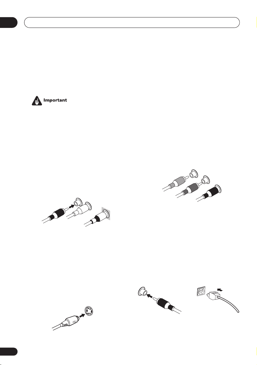
Audio/Video cords
Use audio/video cords (not supplied) to
connect the audio/video components and a
video cord to connect the monitor TV.
Connect red plugs to R (right), white plugs to
L (left), and the yellow plugs to
Be sure to insert completely.
R
L
VIDEO
VIDEO
.
Component video cords
Use component video cords to get the best
possible color reproduction of your video
source. The color signal of the TV is divided
into the luminance (
(
PB
and PR) signals and then output. In this
way, interference between the signals is
avoided. Connect from the component video
jacks on the rear of the receiver to the component video jacks on the video component you
are hooking up.
Green
Y
) signal and the color
Y
P
B
Blue
Red
P
R
16
En
S-video cables
Use S-video cables (not supplied) to get
clearer picture reproduction than regular
video cords.
Connect from an S-video jack on the rear of
the receiver to an S-video jack on the video
component you are hooking up.
Be sure to insert completely.
S VIDEO
Digital audio coaxial cords/
Optical cables
Commercially available digital audio coaxial
cords (standard video cords can also be used)
or optical cables (not supplied) are used to
connect digital components to this receiver.
Be sure to insert completely.
Digital audio coaxial cord
(or standard video cord)
Optical cable
Page 17
Connecting up
O
P
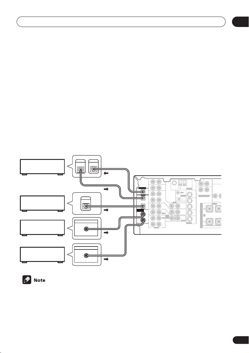
Connecting digital components
The easiest way to hook up this receiver for surround sound is to use a digital input. You can do
this by either coaxial or optical connections (you do not need to do both). The quality of these
two types of connections is the same but since some digital components only have one type of
digital terminal, it is a matter of matching like with like (for example, the coaxial output from the
component to coaxial input on the receiver). This receiver has four digital inputs (two coaxial
inputs and two optical inputs) on the rear panel. Connect your digital components as shown
below.
There is one digital output jack which is marked
input on a digital recorder (for example an MD, DAT or CD-R) you can make direct digital recordings with this unit.
When connecting your equipment, always make sure the power is turned off and the power cord
is disconnected from the AC outlet.
• The arrows indicate the direction of the signal.
DIGITAL
CD recorder
Satellite tuner
CD player
OUT
DIGITAL
OUT
DIGITAL OUT
COAX
DIGITAL
IN
DIGITAL OUT
DIGITAL OUT
OPT
OPT
2
(DVR/VCR)
OPT
1
(TV/
SAT)
ASSIGNABLE
COAX
DIGITAL IN
2
(CD)
COAX
1
(DVD
/LD)
. If you connect this to the optical
CEN-
SUB WOOFER
AUX
IN
IN
OUT
IN
IN
IN
OUT
IN
R
AUDIO
FM UNBAL
Ω
75
CD
DVR/
VCR
TV/
SAT
DVD
/LD
FRONT
REC
CD-R
/ TAPE
/ MD
PLAY
L
OUT
CONTROL
IN
VIDEO
IN
OUT
IN
MONITOR
OUT
D V D
5.1CH
SUB
INPUT
WOOFER
IN
PREOUT
TER
AM
LOOP
ANTENNA
MONITOR OUT
S-VIDEO
OUT
DVR/
VCR
IN
TV/
SAT
IN
DVD
/LD
IN
SURROUND
DVD 5.1CH INPUT
RL
S
P
E
A
A
K
E
R
S
LR
FRONT
MONIT
Y
04
DVD player
DIGITAL OUT
COAX
• If you have an LD player, you need to make special connections to ensure you can play
RF format LDs on your system. If this is the case, hook up your DVD or LD player directly to
an RF demodulator using both the
2
RF output and either a coaxial or optical digital
connection. We also recommend hooking up your digital components to analog audio jacks
as well. Make sure the RF demodulator digital in switch is set correctly (optical or coaxial
depending on the connection). See the component's instruction manual if you are unsure
about its input and output jacks.
2
17
En
Page 18
04
F
C
PLAY
OUTPUT
Connecting up
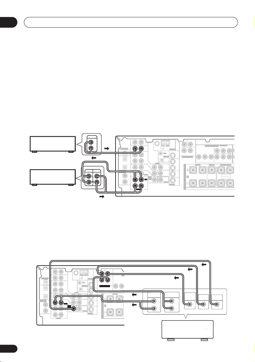
Connecting audio components
To begin set up, connect your analog audio components (such as a cassette deck) to the jacks.
For components you want to record with, you need to hook up four plugs to the receiver (a set
of stereo inputs and a set of stereo outputs), but for components that only play, you only need
to hook up one set of stereo plugs. You must also hook up your digital components to analog
audio jacks if you want to record to/from digital components (like an MD) to/from analog components. See page 17 for more on digital connections.
When connecting your equipment, always make sure the power is turned off and the power cord
is disconnected from the AC outlet.
• The arrows indicate the direction of the audio signal.
CEN-
SUB WOOFER
CD player
CD-R/Tape/MD deck
AUX
IN
DIGITAL OUT
IN
OPT
OPT
OUT
2
(DVR/VCR)
IN
OPT
1
(TV/
IN
SAT)
RE
ASSIGNABLE
DIGITAL IN
COAX
2
IN
(CD)
COAX
1
OUT
(DVD
/LD)
IN
R
AUDIO
FM UNBAL
Ω
75
CD
DVR/
VCR
TV/
SAT
DVD
/LD
FRONT
REC
CD-R
/ TAPE
/ MD
PLAY
L
LOOP
OUT
CONTROL
IN
VIDEO
IN
OUT
IN
MONITOR
OUT
D V D
5.1CH
SUB
INPUT
WOOFER
IN
PREOUT
TER
AM
ANTENNA
MONITOR OUT
S-VIDEO
OUT
DVR/
VCR
IN
TV/
SAT
IN
DVD
/LD
IN
DVD 5.1CH INPUT
LR
SURROUND
FRONT
RL
S
P
E
A
A
K
E
R
S
MONITOR OUT
YP
ASSIGNABLE
COMPONENT VIDEO
(
)
DVD/ LD
IN
BPR
YPBP
(
)
TV / SAT
IN
ø
CENTER
SURROUND BACK
RL
SINGLE
SEE INSTRUCTION
MANUAL
¥
R
18
En
Connecting DVD 5.1 channel components
If you prefer to use a seperate component for decoding DVDs, you can connect a decoder or a
DVD player with multi-channel analog outputs to the multi-channel inputs of this receiver. Note
that the multi-channel input can only be used when
When connecting your equipment, always make sure the power is turned off and the power cord
is disconnected from the AC outlet.
• The arrows indicate the direction of the signal.
CEN-
SUB WOOFER
TER
AM
LOOP
ANTENNA
MONITOR OUT
SURROUND
DVD 5.1CH INPUT
IN
OUT
DVR/
VCR
S
IN
P
E
TV/
SAT
A
IN
A
K
DVD
/LD
E
IN
S-VIDEO
R
S
COMPONENT VIDEO
MONITOR OUT
LR
YP
BPR
FRONT
RL R
DIGITAL OUT
(DVR/VCR)
ASSIGNABLE
DIGITAL IN
AUX
IN
IN
OPT
OPT
OUT
2
IN
OPT
1
(TV/
IN
SAT)
COAX
2
IN
(CD)
COAX
1
OUT
(DVD
/LD)
IN
R
AUDIO
FM UNBAL
75
Ω
CD
OUT
DVR/
VCR
TV/
SAT
/ TAPE
PLAY
L
CONTROL
VIDEO
IN
OUT
IN
DVD
MONITOR
/LD
OUT
FRONT
D V D
5.1CH
SUB
INPUT
REC
WOOFER
IN
CD-R
/ MD
PREOUT
DVD 5.1 ch
ASSIGNABLE
(
)
DVD/ LD
IN
¥
YPBP
(
)
TV / SAT
IN
ø
SURROUND BACK
RL
SINGLE
SEE INSTRUCTION
MANUAL
LL
R
RR
FRONT
FRONT
OUTPUT
SURROUND
BACK
CENTER
PREOUT
SURROUND
SURROUND
LR L
L
R
DVD/multi-channel decoder
with multi-channel analog
output jacks
is selected (see page 41).
FRONTCENTER SURROUND
OUTPUT
SUB
CENTER
WOOFER
OUTPUT
AC OUTLET
L
B
R
OUTPUT
VIDEO
OUTPUT
Page 19
Connecting up
E
N
O
B
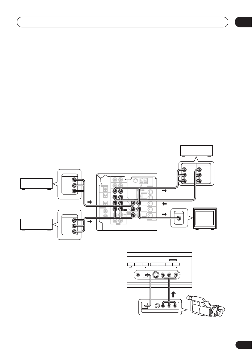
Connecting video components
Connect your video components to the jacks as shown below. With digital video components
(like a DVD player), you must use the connections shown on this page for the video signal, but
in order to hear a digital source (like a DVD) you should hook up the audio to a digital input (see
page 17). It is also a good idea to hook up your digital components with analog audio connections (see page 18).
For better quality video, you can hook up using the component video jacks or the S-video jacks
(quality descends in this order) on the rear of the receiver instead of the regular video jacks.
Make sure they are connected to the video component using the same kind of connection.
When connecting your equipment, always make sure the power is turned off and the power cord
is disconnected from the AC outlet.
• The arrows indicate the direction of the signal
Video deck
INPUT
OUTPUT
VIDEO
VIDEO
L
L
R
R
ASSIGNABLE
LL
(
)
DVD/ LD
IN
¥
YPBP
R
RR
(
)
TV / SAT
FRONT
SURROUND
IN
ø
SURROUND BACK
CENTER SURROUND
RL
SINGLE
SEE INSTRUCTION
MANUAL
TV (monitor)
SURR
TV tuner
(or Satellite tuner)
DVD or LD player
OUTPUT
VIDEO
OUTPUT
VIDEO
CEN-
SUB WOOFER
AUX
IN
L
R
L
DIGITAL OUT
(DVR/VCR)
ASSIGNABLE
DIGITAL IN
IN
OPT
OPT
OUT
2
IN
OPT
1
(TV/
IN
SAT )
COAX
2
IN
(CD)
COAX
1
OUT
(DVD
/LD)
IN
R
FM UNBAL
75
Ω
CD
DVR/
VCR
TV/
SAT
DVD
/LD
FRONT
REC
CD-R
/ TAPE
PLAY
L
AUDIO
OUT
CONTROL
VIDEO
IN
OUT
IN
MONITOR
OUT
D V D
5.1CH
SUB
INPUT
WOOFER
IN
PREOUT
/ MD
TER
AM
LOOP
ANTENNA
MONITOR OUT
SURROUND
DVD 5.1CH INPUT
IN
OUT
DVR/
VCR
S
IN
P
E
TV/
SAT
A
IN
K
DVD
/LD
E
IN
S-VIDEO
R
S
COMPONENT VIDEO
MONITOR OUT
LR
BPR
YP
FRONT
RL R
A
INPUT
VIDEO
R
04
CE
PR
L
Connecting to the front panel video
terminal
Front video connections are accessed via the
front panel using the
standard audio/video jacks as well as an
S-video jack and an optical input. Hook them
up the same way you made the rear panel
connections.
VIDEO
button. There are
STEREO/
SIGNAL
DIRECT
SELECT
DE
MCACC
VSX-D914
MIDNIGHT/
LOUDNESS
DIGITAL OUT
SPEAKERS
S-VIDEODIGITAL INSETUP MIC VIDEO
SB CH
MODE
VIDEO INPUT
VIDEO OUTPUT
TONE
LAUDIOR
LV
MULTI JOG
QUICK SETUP
R
Video
camera
(etc.)
19
En
Page 20
04
Connecting up
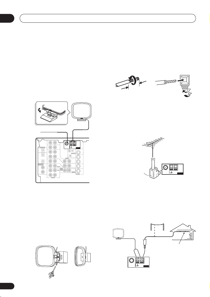
Connecting antennas
Connect the AM loop antenna and the FM
wire antenna as shown below. To improve
reception and sound quality, connect external
antennas (see
below). Always make sure that the receiver is
switched off and unplugged from the wall
outlet before making or changing any
connections.
FM wire antenna
Connect the FM wire antenna and fully extend
vertically along a window frame or another
suitable place that gives good reception.
AM loop antenna
Assemble the antenna and connect to the
receiver. Attach (if necessary) and face in the
direction that gives the best reception.
Using external antennas
FM wire antenna
AUX
DIGITAL OUT
ASSIGNABLE
DIGITAL IN
OPT
OPT
(DVR/VCR)
OPT
(TV/
SAT)
COAX
(CD)
COAX
(DVD
/LD)
IN
IN
OUT
2
IN
1
IN
2
IN
1
OUT
IN
FM UNBAL
Ω
75
CD
DVR/
VCR
VIDEO
IN
TV/
SAT
IN
DVD
/LD
FRONT
D V D
5.1CH
INPUT
REC
IN
CD-R
/ TAPE
/ MD
PLAY
R
L
AUDIO
AM loop
antenna
AM
LOOP
ANTENNA
MONITOR OUT
OUT
CONTROL
IN
OUT
MONITOR
OUT
SUB
WOOFER
PREOUT
S-VIDEO
OUT
DVR/
VCR
IN
TV/
SAT
IN
DVD
/LD
IN
Antenna snap connectors
Twist the exposed wire strands together and
insert into the hole, then snap the connector
shut.
3/8 in. (10mm)
Using external antennas
To improve FM reception
Use an F connector to connect an external FM
antenna.
F connector
To improve AM reception
Connect a 15–18 feet length of vinyl-coated
wire to the AM antenna terminal without
disconnecting the supplied AM loop antenna.
For the best possible reception, suspend horizontally outdoors.
Outdoor
antenna
FM UNBAL
75
15–18 ft. (5–6m)
Indoor antenna
(vinyl-coated wire)
AM
Ω
LOOP
ANTENNA
20
En
FM UNBAL
75
AM
Ω
LOOP
ANTENNA
Page 21
Connecting up
E
UNBAL
COMPONENT VIDEO
CEN-
R
SURROU
BA
INPUT
A
N
SW
subwoofer
surround
bac
p
r
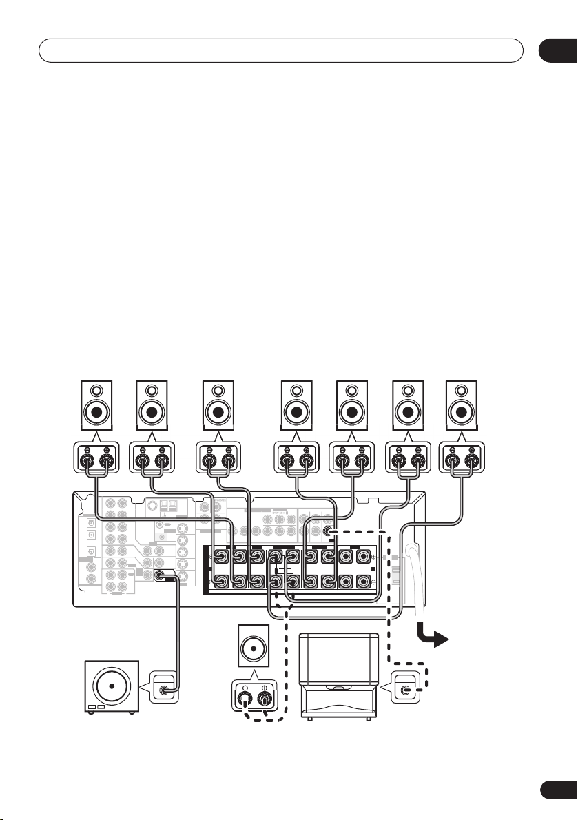
Connecting the speakers
A complete setup of eight speakers (including the subwoofer) is shown below, but everyone’s
home setup will vary. Simply connect the speakers you have in the manner shown below. The
receiver will work with just two stereo speakers (the front speakers in the diagram) but using at
least three speakers is recommended, and a complete setup is best for surround sound. If
you’re not using a subwoofer, change the front speaker setting (see
to large.
Make sure you connect the speaker on the right to the right terminal and the speaker on the left
to the left terminal. Also make sure the positive and negative (
match those on the speakers. You can use speakers with a nominal impedance between 6–16
(please see
impedance of less than 8
Switching the speaker impedance
Ω
).
on page 67 if you plan to use speakers with an
Be sure to complete all connections before connecting this unit to the AC power source.
Speaker setting
+/–
) terminals on the receiver
on page 43)
04
Ω
Front speakers
Center speaker
Surround speakers
LR C LSRS
DIGITAL OUT
IN
OPT
OPT
OUT
2
(DVR/VCR)
IN
OPT
1
(TV/
IN
SAT)
ASSIGNABLE
COAX
DIGITAL IN
2
IN
(CD)
COAX
1
OUT
(DVD
/LD)
IN
Powered
AUX
75
Ω
CD
DVR/
VCR
VIDEO
IN
TV/
SAT
IN
DVD
/LD
FRONT
D V D
5.1CH
INPUT
REC
IN
CD-R
/ TAPE
/ MD
PLAY
R
L
AUDIO
OUT
CONTROL
OUT
MONITOR
OUT
SUB
WOOFER
PREOUT
LOOP
IN
ANTENNA
MONITOR OUT
OUT
DVR/
VCR
TV/
SAT
DVD
/LD
S-VIDEO
Passive
TE
MONITOR OUT
LR
SURROUND
DVD 5.1CH INPUT
IN
IN
IN
BPR
YP
FRONT
RL R
S
P
E
A
A
K
E
R
S
ASSIGNABL
R
RR
FRONT
CENTER
PREOUT
SURROUND
LR L
YPBP
(
)
TV / SAT
IN
ø
SURROUND BACK
RL
SINGLE
SEE INSTRUCTION
MANUAL
FRONTCENTER SURROUND
subwoofer
or single
k
eake
s
TV
Surround back speakers
SBL SBR
AC OUTLET
B
UDIO I
21
En
Page 22
04
Connecting up
• When using the speaker on your TV as the
center speaker (
PREOUT
input jack on your TV. In this case the
center speaker shown is unnecessary.
• If you are using only one surround back
speaker, connect the positive wire to the
right channel (
tive wire to the left channel (
(see illustration on page 10).
• If you select subwoofer (
Surround back speaker setting
you can hook up a subwoofer instead of
speakers to the surround back speaker
terminals. Connect the positive wire to the
right channel (
tive wire to the left channel (
(see illustration on page 11).
C
), connect the
jack on this unit to the audio
+
) terminal, and the nega-
+
) terminal, and the nega-
–
) terminal
SB SW
on page 44
–
) terminal
CENTER
) in the
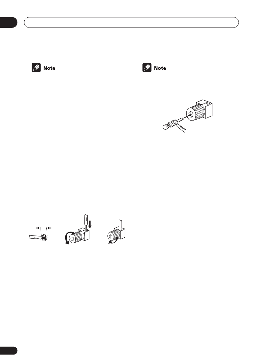
Speaker terminals
12 3
3/8 in. (10mm)
1 Twist exposed wire strands together.
2 Loosen speaker terminal and insert
exposed wire.
Make sure that all the bare speaker wire is
twisted together and inserted fully into the
speaker terminal. If any of the bare speaker
wire is touching the back panel when you
switch the unit on, the power may cut off as a
safety measure. Use good quality speaker
wire to connect the speakers to the receiver.
3 Tighten terminal.
• The speaker terminals also accept single
banana plugs. (Refer to speaker manual
for details.)
A and B speaker systems
The receiver has two speaker systems: A and
B. A is the main system supporting the full
speaker setup. If you switch on both A and B
speaker systems, only the front speakers and
the (active) subwoofer will be audible. No
sound will come from the center, surround, or
surround back speakers, but multi-channel
sources will be down-mixed to the active
speakers so no sound will be lost. Similarly, if
you choose just the B system you‘ll only hear
the front speakers connected to the B system
and multi channel sources will be downmixed to these two speakers.
• Press the SPEAKERS button on the
front panel to switch between speaker
systems (A, B or both).
Hints on speaker placement
Speakers are usually designed with a particular placement in mind. Some are designed
to be floorstanding, while others should be
placed on stands to sound their best. Some
should be placed near a wall; others should
be placed away from walls. We have provided
a few tips on getting the best sound from your
speakers (following), but you should also
follow the guidelines on placement that the
speaker manufacturer provided with your
particular speakers to get the most out of
them.
22
En
Page 23

Connecting up
04
• Place the front left and right speakers at
equal distances from the TV.
• When placing speakers near the TV, we
recommend using magnetically shielded
speakers to prevent possible interference,
such as discoloration of the picture when
the TV is switched on. If you do not have
magnetically shielded speakers and
notice discoloration of the TV picture,
move the speakers farther away from the
TV.
• Place the center speaker above or below
the TV so that the sound of the center
channel is localized at the TV screen.
• If possible, place the surround speakers
slightly above ear level.
• Try not to place the surround speakers
farther away from the listening position
than the front and center speakers. Doing
so can weaken the surround sound effect.
• To achieve the best possible surround
sound, install your speakers as shown
below. Be sure all speakers are installed
securely to prevent accidents and
improve sound quality.
Overhead view of speaker setup
Front
Left
Surround
Left
Listening Position
Surround Back Surround Back
3-D view of
Left Right
Single Surround Back Speaker
6.1 channel
Front
RightCenter
Subwoofer
Surround
Right
speaker setup
• If you choose to install the center speaker
on top of the TV, be sure to secure it with
putty, or by other suitable means, to
reduce the risk of damage or injury
resulting from the speaker falling from the
TV in the event of external shocks such as
earthquakes.
• Make sure no exposed speaker wire is
touching the rear panel, this may cause
the receiver to turn off automatically.
3-D view of
7.1 channel
speaker setup
23
En
Page 24

04
R
Connecting up
Connecting additional amplifiers
This receiver has more than sufficient power for any home use, however it is possible to add
additional amplifiers to every channel on this receiver. Make the connections shown below to
add amplifiers to power your speakers. Always make sure that the receiver is switched off and
unplugged from the wall outlet before making or changing any connections.
• The arrows indicate the direction of the audio signal.
DIGITAL OUT
(DVR/VCR)
ASSIGNABLE
DIGITAL IN
ANALOG IN
L R
ANALOG IN
AUX
IN
IN
OPT
OPT
OUT
2
IN
OPT
1
(TV/
IN
SAT)
COAX
2
IN
(CD)
COAX
1
OUT
(DVD
/LD)
IN
R
FM UNBAL
Ω
75
CD
DVR/
VCR
VIDEO
IN
TV/
SAT
IN
DVD
/LD
FRONT
D V D
5.1CH
INPUT
REC
IN
CD-R
/ TAPE
/ MD
PLAY
L
AUDIO
LOOP
OUT
CONTROL
IN
OUT
MONITOR
OUT
SUB
WOOFER
PREOUT
IGNABLE
)
/ LD
IN
¥
AM
ANTENNA
MONITOR OUT
PBP
)
SAT
IN
ø
OUT
DVR/
ROUND BACK
VCR
IN
TV/
SAT
SINGLE
IN
SEE INSTRUCTION
MANUAL
DVD
/LD
IN
S-VIDEO
LL
R
RR
FRONT
L
SURROUND
BACK
CENTER
PREOUT
SURROUND
R
LR L
L
FRONTSURROUND
AC OUTLET
ANALOG IN
B
ANALOG IN
Front channel
amplifier
Surround channel
amplifier
R
Surround back
channel amplifier
Center channel
amplifier
INPUT
Powered
subwoofer
• To hear sound only from the pre-outs, disconnect any speakers that are connected directly
to the receiver.
• If you’re not using a subwoofer, change the front speaker setting (see
Speaker setting
on
page 43) to large.
24
En
Page 25

Connecting up
04
AC outlet
Power supplied through this outlet is turned
on and off by the receiver's power switch.
Total electrical power consumption of
connected equipment should not exceed 100
W (0.8 A).
AC OUTLET
SWITCHED
100 W MAX
0.8 A MAX
• Do not connect a monitor, TV set, heater,
or similar appliance to this unit’s AC
outlet.
• Do not connect appliances with high
power consumption to the AC outlet in
order to avoid overheating and fire risk.
This can also cause the receiver to
malfunction.
Power cord caution
Handle the power cord by the plug. Do not
pull out the plug by tugging the cord and
never touch the power cord when your hands
are wet as this could cause a short circuit or
an electric shock. Do not place the unit, a
piece of furniture, etc., on the power cord, or
pinch the cord. Never make a knot in the cord
or tie it with other cords. The power cords
should be routed such that they are not likely
to be stepped on. A damaged power cord can
cause a fire or give you an electrical shock.
Check the power cord once in a while. When
you find it damaged, ask your nearest Pioneer
authorized service center or your dealer for a
replacement.
Operating other Pioneer
components
By connecting a control cord (optional), you
can point the remote controls of other Pioneer
components at the receiver’s remote sensor.
The remote control signals are received by the
remote sensor of this unit, and sent to the
other devices via the
on the receiver.
OUT
CONTROL
IN
CONTROL OUT
CONTROL
IN
OUT
terminal
• This unit should be disconnected by
removing the power plug from the wall
socket when not in regular use (ex. when
on vacation).
Receiver
Remote
control
unit
Other Pioneer products
with CONTROL terminals
Connect to CONTROL
terminal of other
Pioneer products
25
En
Page 26

04
DVD
N
STANDBY
Connecting up
Using this receiver with a
Pioneer plasma display
If you have a Pioneer plasma display (models
PRO-1110HD, PRO-910HD, PDP-5040HD,
PDP-4340HD), you can use an SR+ cable
(see note below) to connect it to this unit and
take advantage of various convenient
features, such as automatic video input
switching of the plasma display when the
input is changed.
CONTROL
OUT
Pioneer plasma
DIGITAL OUT
(DVR/VCR)
ASSIGNABLE
DIGITAL IN
IN
IN
OPT
OPT
OUT
2
IN
OPT
1
(TV /
IN
SAT )
COAX
2
IN
(CD)
COAX
1
OUT
(DVD
/LD)
IN
R
AUDIO
FM UNBAL
Ω
75
CD
DVR/
VCR
VIDEO
IN
TV /
SAT
IN
DVD
/LD
FRONT
D V D
5.1CH
INPUT
REC
IN
CD-R
/ TAPE
/ MD
PLAY
L
AUX
• If you connect to a Pioneer plasma display
using an SR+ cable, you will need to point
the remote control at the plasma display
remote sensor to control the receiver. In
this case, you won’t be able to to control
the receiver using the remote control if
you switch the plasma display off.
LOOP
OUT
CONTROL
IN
OUT
MONITOR
OUT
SUB
WOOFER
PREOUT
AM
ANTENNA
MONITOR OUT
S-VIDEO
display
OUT
DVR/
VCR
IN
TV/
SAT
IN
DVD
/LD
IN
CEN-
SUB WOOFER
TER
SURROUND
DVD 5.1CH INPUT
S
P
E
A
A
K
E
R
S
LR
R
• Use a 3-ringed miniplug SR+ cable to
connect the CONTROL IN jack of this
receiver with the CONTROL OUT of your
plasma display.
Before you can use the extra SR+ features,
you need to make a few settings in the
receiver. See
displays
DVD player
AUDIO I
SR+ control for Pioneer plasma
on page 48 for detailed instructions.
VIDEO
INPUT 1
Pioneer plasma
display
VIDEO
INPUT 2
Satellite receiver, etc
TV/SAT
AUDIO IN
VSX-D914
AUDIO/VIDEOMULTI-CHANNEL RECEIVER
MULTI JOG
ENTER
MASTER VOLUME
MULTI JOG
ADVANCED
STEREO/
SIGNAL
MIDNIGHT/
SB CH
TUNING
MPX
BAND
PHONES
MULTI JOG
STANDARD SPEAKERS
SURROUND
DIRECT
LISTENING MODE
MCACC
INPUT ATTFL DIMMER
TONE
QUICK SETUP
SELECT
LOUDNESS
MODE
VIDEO INPUT
S-VIDEODIGITAL INSETUP MIC VIDEO
UPDOWN
LAUDIOR
VSX-D814/914
To make the most of the SR+ features, you
should connect your source components
(DVD player, etc.) in a slightly different way to
that described in this chapter. For each
component, connect the video output directly
to the plasma display, and just connect the
audio (analog and/or digital) to this receiver.
• The 3-ringed SR+ cable from Pioneer is
commercially available under the part
number ADE7095. Contact the Pioneer
Customer Support division for more information on obtaining an SR+ cable.
26
En
Page 27

Controls and displays
O
C
C
/
R
UX
Chapter 5:
Controls and displays
Front panel
05
TV/SATDVR/VCRVIDE
D-R
A
TUNE
D
STANDBY/ON
PHONES
8
10 11 12 13 14 15 16 17
9
ADVANCED
STANDARD SPEAKERS
SURROUND
LISTENING MODE
INPUT ATT FL DIMMER
TUNER EDIT
MULTI JOG
STATION
TUNING
MPX
BAND
CLASS
26 25 24 23 22 21 18
1 STANDBY/ON
Switches the receiver between on and
standby.
2 Input select buttons
Press to select an input source (selected
source button will light).
3 Remote sensor
Receives the signals from the remote control.
4 MCACC indicator
Lights after MCACC setup (page 49,
model only –
page 14).
VSX-D914
3 4
5 6
AUDIO/VIDEO MULTI-CHANNEL RECEIVER
ENTER
MASTER VOLUME
VSX-D914
MULTI JOG
UPDOWN
7
STEREO/
DIRECT
SIGNAL
MIDNIGHT/
SELECT
LOUDNESS
MCACC
DIGITAL INSETUP MIC VIDEO
S-VIDEO
SB CH
MODE
VIDEO INPUT
TONE
L AUDIO R
MULTI JOG
QUICK SETUP
1920
5 ENTER
6 MULTI JOG dial
The
MULTI JOG
dial performs a number of
tasks. Use it to select options after pressing
TONE, QUICK SETUP
or
TUNER EDIT
7 MASTER VOLUME
8 PHONES jack
Use to connect headphones. When the headphones are connected, there is no sound
output from the speakers.
.
27
En
Page 28

05
Controls and displays
9 STATION +/– buttons
Selects station presets when using the tuner
(page 54).
10 TUNING +/– buttons
Selects the frequency when using the tuner
(page 53).
11 LISTENING MODE buttons
STANDARD
Press for Standard decoding and to
switch between the various Pro Logic IIx
and Neo:6 options (page 35).
ADVANCED SURROUND
Use to switch between the various
surround modes
STEREO/DIRECT
Switches between direct and stereo playback. Direct playback bypasses the tone
controls and channel levels for the most
accurate reproduction of a source
(page 36).
12 SIGNAL SELECT
Use to select an input signal (page 37).
13 MIDNIGHT/LOUDNESS
Use Midnight when listening to movie
soundtracks at low volume. Use Loudness to
boost the bass and treble at low volume
(page 40).
14 SPEAKERS
Use to cycle through the speaker system:
A B A+B
change the speaker impedence (
the speaker impedance
15 SB CH MODE
Selects the Surround back channel mode
(page 38).
16 TONE
Press this button to access the bass and
treble controls, which you can then adjust
with the
(page 22). Also used to
MULTI JOG
(page 35).
on page 67).
dial.
Switching
17 QUICK SETUP
See
Using the Quick Setup
18 VIDEO INPUT
See
Connecting to the front panel video
terminal
19 DIGITAL IN
See
terminal
20 MCACC SETUP MIC
(VSX-D914 model only)
Connect the microphone supplied with your
system to the
using the auto surround setup (MCACC)
(page 14).
21 FL DIMMER
Use this button to make the fluorescent
display (FL) dimmer or brighter.
22 INPUT ATT
Use to attenuate (lower) the level of an analog
input signal to prevent distortion.
23 MPX
Press to receive a radio broadcast in mono
(page 53).
24 BAND
Switches between AM and FM radio bands
(page 53).
25 CLASS
Switches between the three banks (classes)
of station presets
26 TUNER EDIT
Press to memorize and name a station for
recall
on page 19.
Connecting to the front panel video
on page 19.
MCACC SETUP MIC
(page 54).
(page 54).
on page 12.
jack when
28
En
Page 29

Controls and displays
Display
123456789 10
x
05
11
12 15
1 SIGNAL SELECT indicators
Lights to indicate the type of input signal
assigned for the current component:
AUTO
Lights when
SB
Depending on the source, this lights
when a signal with surround back
channel encoding is detected.
DIGITAL
Lights when a digital audio signal is
detected.
2
DIGITAL
Lights when a Dolby Digital encoded
signal is detected.
ANALOG
Lights when an analog signal is detected.
DTS
Lights when a source with DTS encoded
audio signals is detected.
2
When the
on, this lights to indicate decoding of a DTS
signal.
AUTO
STANDARD
signal select is on.
mode of the receiver is
13
32 DIGITAL
When the
on, this lights to indicate decoding of a Dolby
Digital signal.
42 PRO LOGIC II (x
When the (
the receiver is on, this lights to indicate Pro
Logic II decoding. The
Logic IIx decoding (see
sound
5 VIR.SB
Lights during Virtual surround back
processing.
6 DIRECT
Lights when source direct playback is
selected. Direct playback bypasses the tone
controls and channel levels for the most accurate reproduction of a source.
7 MIDNIGHT
Lights during Midnight listening.
8 SLEEP
Lights when the receiver is in sleep mode.
9 ATT
Lights when
(reduce) the level of the analog input signal.
10 Speaker indicator
Shows the speaker system currently in use.
STANDARD
STANDARD
on page 35 for more on this).
INPUT ATT
mode of the receiver is
x
1614
)
) Pro Logic II mode of
lights to indicate Pro
Listening in surround
is used to attenuate
29
En
Page 30

05
Controls and displays
11 Character display
12 Neo:6
When the (
receiver is on, this lights to indicate NEO:6
processing.
13 ADV.SURR. (Advanced Surround)
Lights when one of the Advanced Surround
modes has been selected.
14 LOUDNESS
Lights when
15 TUNER indicators
16 Master volume level
Shows the overall volume level.
cates the minimum level, and
the maximum level.
Depending on your level settings for each
channel, the maximum volume can range
between –10 dB and –0 dB.
STANDARD
LOUDNESS
STEREO
Lights when a stereo FM broadcast is
being received in auto stereo mode.
MONO
Lights when the mono mode is set using
the
MPX
button.
TUNED
Lights when a broadcast is being
received.
) NEO:6 mode of the
has been selected.
---dB
indi-
- 0 dB
indicates
30
En
Page 31

Controls and displays
05
Remote control
INPUT
RECEIVER
1
SELECT
2
DVD/LD TV/SAT
CD
MULTI CONTROL
CD-R/TAPE
3
4
INPUT ATT FL DIMMER SR
+
10
D.ACCESS
TOP MENU
5
6
7
8
9
10
DTV MENU
T.EDIT
GUIDE
TV VOL
DTV ON/OFF
TUNER
DISPLAY
MPX
AUDIO
STANDRAD
MIDNIGHT/
LOUDNESS
SHIFT
ST ST
TV CONTROL
INPUT
SELECT
CH RETURN
SUBTITLE
RECEIVER CONTROL
ADV. SURR STEREO SLEEP
TEST TONE
CH SELECT
RECEIVER
1 RECEIVER
This switches between standby and on for this
receiver.
2 INPUT SELECT
Use to select the input source.
SETUP
TUNE
ENTER
TUNE
DTV INFOREC MUTE
REC STOP
SOURCE
DVR/VCR
TV CONT
TUNER
RECEIVER
ENTER
CLASS
RETURN
TV CH
VOL
HDD
DVD
CH
CH
LEVEL EFFECT
DISC
MENU
MCACC
SETUP
BAND
11
12
13
14
3 MULTI CONTROL buttons
Press to select control of other components
(see
Controlling the rest of your system
on
page 57).
4 Number buttons and other receiver/
component controls
Use the number buttons to directly select a
radio frequency (page 53) or the tracks on a
CD, DVD, etc.
DISC (ENTER)
can be used to enter
commands for TV or DTV, and can also be
used to select a disc in a multi-CD player.
The following are accessed by pressing the
RECEIVER
button first:
INPUT ATT
Attenuates (lowers) the level of an analog
input signal to prevent distortion.
FL DIMMER
Dims or brightens the display.
SR+
Switches the SR+ mode on/off.
5 Tuner/component control buttons/
MCACC
The following button controls (except
SETUP
) can be accessed after you have
selected the corresponding
CONTROL
button (
TUNER, DVD, TV/SAT
MULTI
MCACC
,
etc.)
D. ACCESS
After pressing, you can access a radio
station directly using the number buttons
(page 53).
TOP MENU
Displays the disc ‘top’ menu of a DVD.
DTV MENU
Displays menus on a digital TV.
T. EDIT
Press to memorize and name a station for
recall (page 54).
31
En
Page 32

05
32
En
Controls and displays
GUIDE
Displays the guides on a digital TV.
CLASS
Switches between the three banks
(classes) of radio station presets
(page 54).
MENU
Displays the disc menu of DVD-Video
discs. It also displays TV and DTV menus.
MCACC SETUP
(Press
RECEIVER
Use to setup your speaker system using
Multi-Channel Acoustic Calibration
(MCACC) (page 49,
page 14).
BAND
Switches between the tuner AM and FM
bands (page 53).
RETURN
Press to return to the previous menu with
DVDs or to select closed captioning with
DTV.
6
Use the arrow buttons when setting up your
surround sound system (see page 42). Also
used to control DVD menus/options and for
deck 1 of a double cassette deck player. Use
the
TUNE +/–
cies and use
(page 54).
7 TV CONTROL buttons
These buttons are dedicated to control the TV
assigned to the
only have one TV to hook up to this system
assign it to the
button. If you have two TVs, assign the main
TV to the
TV
Use to turn on/off the power of the TV.
TV VOL +/–
Use to adjust the volume on your TV.
TV CONT
first to access)
VSX-D914 model only –
(TUNE/ST +/–) /ENTER
buttons to find radio frequen-
ST +/–
to find preset stations
TV CONT
TV CONT MULTI CONTROL
button. Thus if you
button.
INPUT SELECT
Use to select the TV function.
TV CH +/–
Use to select channels.
8 Component control buttons
The main buttons (, , etc.) are used to
control a component after you have selected
it using the
The controls above these buttons can be
accessed after you have selected the corresponding
example
(when connected to a DTV)).
MULTI CONTROL
MULTI CONTROL
DVD/LD, DVR/VCR
DTV ON/OFF
Switches a digital TV on/off.
DTV INFO
Use to bring up information screens on a
digital TV.
MUTE
Mutes the sound (or restores the sound if
it has been muted).
TUNER DISPLAY
Displays TV information on-screen.
MPX
(Press
Switches between stereo and mono
reception of FM broadcasts. If the signal
is weak then switching to mono will
improve the sound quality (page 53).
AUDIO
Changes the audio language or channel
on DVD discs.
CH RETURN
Returns to the last channel selected with
DTV, SAT and some TVs.
SUBTITLE
Displays/changes the subtitles included
in multilingual DVD-Video discs.
CH +/–
Use to select channels when using a TV,
VCR, DVR, etc.
TUNER
buttons.
button (for
or
TV/SAT
first to access)
Page 33

Controls and displays
05
The following DVR controls can be accessed
by pressing
Starts recording.
REC STOP
Stops recording.
HDD/DVD
These buttons switch between the hard
disk and DVD controls for DVD/HDD
recorders.
9 RECEIVER CONTROL buttons
STANDARD
Press for Standard decoding and to
switch between the various Pro Logic IIx
and Neo:6 options (page 35).
ADV. SURR.
Use to switch between the various
surround modes
STEREO
Switches between direct and stereo playback. Direct playback bypasses the tone
controls and channel levels for the most
accurate reproduction of a source
(page 36).
SLEEP
Use to put the receiver in sleep mode and
select the amount of time before the
receiver turns off (page 41).
MIDNIGHT/LOUDNESS
Switches to Midnight or Loudness
listening
TEST TONE
Sounds the test tone when setting up the
surround sound of the receiver (page 50).
CH SELECT
Selects a speaker when setting up the
surround sound of the receiver (page 50).
REC
SHIFT
:
(page 40).
(page 35).
LEVEL +/–
Adjusts the levels of the surround sound
of the receiver (page 50).
EFFECT +/–
Adds or subtracts the amount of effect
with different advanced surround modes
(page 35).
10 SHIFT
Press to access the DVR controls above the
component control butttons.
11SOURCE
Press to turn on/off other components
connected to the receiver.
12 Character display (LCD)
This display shows preset codes and other
information when transmitting control
signals.
The following commands are shown when
you’re setting the remote to control other
components (see
system
on page 57):
SETUP
Indicates the setup mode, from which you
choose the options below.
PRESET
See
Selecting preset codes directly
page 57.
LEARN
See
Programming signals from other
remote controls
DIRECT F
See
Direct function
ERASE
See
Erasing one of the remote control
button settings
RESET
See
Erasing all of the remote control
presets
READ ID
See
Confirming preset codes
Controlling the rest of your
on
(VSX-D914 model only)
on page 58.
on page 60.
(VSX-D914 model only)
on page 59.
on page 60.
on page 60.
33
En
Page 34

05
Controls and displays
13 RECEIVER
Switches the remote to control the receiver
(used to select the features above the number
buttons (
button to set up surround sound (page 42,
page 49, page 50).
14 MASTER VOLUME +/–
Use to set the listening volume.
INPUT ATT
, etc). Also use this
34
En
Page 35

Listening to your system
MPX
CH RETURN
HDD
DVD
Chapter 6:
Listening to your system
•
Listening in surround sound
Using this receiver, you can listen to any
source in surround sound. However, the
options available will depend on your speaker
setup and the type of source you’re listening
to.
If you connected surround back speakers, see
also
Using the Surround Back Channel (SB
CH)
on page 38.
AUDIO
SUBTITLE
CH CH
RECEIVER CONTROL
STANDRAD
ADV. SURR STEREO SLEEP
MIDNIGHT/
LOUDNESS
TEST TONE
LEVEL EFFECT
SHIFT
CH SELECT
RECEIVER
• While listening to a source, press
STANDARD.
If the source is Dolby Digital, DTS, or Dolby
Surround encoded, the proper decoding
format will automatically be selected and
shows in the display.
With two channel sources
repeatedly to select from:
2
Pro Logic IIx MOVIE
•
channel sound, especially suited to movie
sources
•
2
Pro Logic IIx MUSIC
channel sound, especially suited to music
sources
•
2
PRO LOGIC
sound (sound from the surround
speakers is mono)
•
NEO:6 CINEMA
especially suited to movie sources
, press
STANDARD
– Up to 6.1
– Up to 6.1
– 4.1 channel surround
– 6.1 channel sound,
NEO:6 MUSIC
cially suited to music sources
• You can’t use the
96kHz PCM or DTS 96kHz/24-bit stereo
sources.
• During playback of a Dolby Digital multichannel source with the
switched
select
MUSIC
Channel (SB CH)
this.
Using the Advanced surround effects
The Advanced surround effects can be used
for a variety of additional surround sound
effects. Most Advanced Surround modes are
designed to be used with film soundtracks,
but some modes are also suited for music
sources. Try different settings with various
soundtracks to see which you like.
• Press ADV. SURR. (ADVANCED
SURROUND) repeatedly to select a
listening mode.
•
ADV. MOVIE
environment of a movie theater, and is
suitable for watching movies.
– 6.1 channel sound, espe-
STANDARD
ON
, you will only be able to
DOLBY EX
. See
or 2 Pro Logic IIx
Using the Surround Back
on page 38 for more on
MPX
CH RETURN
HDD
AUDIO
SUBTITLE
CH
RECEIVER CONTROL
STANDRAD
ADV. SURR STEREO SLEEP
MIDNIGHT/
LOUDNESS
TEST TONE
LEVEL
SHIFT
CH SELECT
RECEIVER
– Simulates the relaxed
mode with
SB CH MODE
DVD
CH
EFFECT
06
35
En
Page 36

06
Listening to your system
•
ADV. MUSIC
– Simulates the acoustic
environment of a large concert hall and is
suitable for music or musical sources.
•
TV SURR.
– This mode produces surround
sound for both mono and stereo TV
sources. It is useful for older movies
recorded with mono soundtracks.
•
SPORTS
– This is designed for sports
programs with alot of action, adding to
the excitement by bringing background
action to the forefront.
•
GAME
– Useful when playing video
games. It works especially well with
sound moving from left to right in game
software with alot of movement.
•
EXPANDED
– This mode is especially
designed to give sound depth to stereo
sources, and lets you hear two-channel
(stereo) signals as simulated multichannel surround sound. Use with Dolby
Pro Logic for a stereo surround effect. You
can also use with Dolby Digital sources
for a wider stereo field than the Standard
modes.
•
6-STEREO
– This can be selected to give
multi-channel sound to a stereo source,
using all of the speakers in your setup.
•
PHONES SURROUND
– When listening
through headphones, you can still get the
effect of overall surround.
• Depending on the source and the sound
mode you have selected, you may not get
sound from the surround back speakers
in your setup. For more on this, refer to
Using the Surround Back Channel (SB CH)
on page 38.
• If you press
phones are connected, the
SURROUND
ADV. SURR.
when the head-
PHONES
mode will automatically be
selected.
• You can’t use the Advanced Surround
listening modes with 96kHz PCM or DTS
96kHz/24 bit sources.
• The Advanced Surround effects can be
adjusted in the range of 10 to 90 by
pressing
EFFECT +/–
. The effect level can
be set for each Advanced Surround mode.
The Standard mode cannot be changed.
Listening in stereo
When you select
hear the source through just the front left and
right speakers (and possibly your subwoofer
depending on your speaker settings). Dolby
Digital and DTS multichannel sources are
downmixed to stereo.
• While listening to a source, press
STEREO for stereo playback.
Press repeatedly to switch between:
•
STEREO
surround settings and you can still use
the Midnight, Loudness, and Tone control
functions.
•
DIRECT
settings so that the audio remains as
close to the source audio signal as
possible.
STEREO
MPX
AUDIO
STANDRAD
MIDNIGHT/
LOUDNESS
SHIFT
or
CH RETURN
HDD
SUBTITLE
CH
RECEIVER CONTROL
ADV. SURR STEREO SLEEP
TEST TONE
LEVEL EFFECT
CH SELECT
RECEIVER
DIRECT
DVD
CH
– The audio is heard with your
– Bypass all effects and surround
, you will
36
En
Page 37

Listening to your system
• If you switch on Midnight listening, Loudness, or the Tone controls when
DIRECT
selected, the receiver automatically
switches to
STEREO
.
Choosing the input signal
• Default setting:
You need to hook up a component to both
analog and digital inputs on the rear of the
receiver to select between input signals.
AUTO
• You may get digital noise when a LD or CD
player compatible with DTS is playing an
analog signal. To prevent noise, make the
is
proper digital connections (page 17) and
set the signal input to
DIGITAL
• Some DVD players don’t output DTS
signals. For more details, refer to the
instruction manual supplied with your
DVD player.
06
.
TUNER EDIT
MULTI JOG
ADVANCED
STEREO/
SIGNAL
TUNING
STATION
CLASS
STANDARD SPEAKERS
LISTENING MODE
MPX
FL DIMMER
INPUT ATT
BAND
MIDNIGHT/
SURROUND
DIRECT
SELECT
LOUDNESS
MCACC
VIDEO INPUT
S-VIDEODIGITAL INSETUP MIC VIDEO
MULTI JOG
SB CH
TONE
QUICK SETUP
MODE
L AUDIO R
• Press SIGNAL SELECT on the front
panel to select the input signal corresponding to the source component.
Each press cycles through the options as
follows:
•
AUTO
– This automatically switches to
DIGITAL
otherwise it remains on
DVD 5.1ch
•
inputs (only appears when
if a digital source is detected,
ANALOG
.
– Selects the multichannel
DVD/LD
is
selected).
•
ANALOG
•
DIGITAL
When set to
– Selects the analog inputs.
– Selects the digital input.
DIGITAL
or
AUTO, 2 DIGITAL
lights when a Dolby Digital signal is input,
and
DTS
lights when a DTS signal is input.
• This receiver can only play back Dolby
Digital, PCM (32kHz–96 kHz) and DTS
digital signal formats (including DTS
96kHz/24 bit). With other digital signal
formats, set to
ANALOG
.
37
En
Page 38

06
Listening to your system
Using the Surround Back
Channel (SB CH)
• Default setting:
You can have the receiver automatically
switch to Dolby Digital EX or DTS-ES
decoding for 6.1 encoded sources (
AUTO
), or you can choose to listen to other
kinds of sources (for example, 5.1 encoded
material) with 6.1 encoding (
encoded sources, a surround back channel
will be generated, but the material may sound
better in the 5.1 format for which it was originally encoded, in which case you can simply
switch the surround back channel off (
OFF
).
The table indicates when you will hear the
surround back channel.
Type of source
DTS-ES/Dolby Digital
Matrix encoded
multi-channel sources
with 6.1 surround
Dolby Digital/DTS
encoded multi-channel
sources
SB ON
SB CH
MODE
ON
AUTO
ON
AUTO
SB ON
STANDARD
decoding
SB
). With 5.1
SB
• Press SB CH MODE (front panel)
repeatedly to cycle the surround back
channel options.
Each press cycles through the options as
follows:
SB ON
SB OFF
SB AUTO
• You can’t use the surround back channel
with headphones, the
mode, or if the
on page 44 is
setting
STEREO
Surround back speaker
SB SW
• You can’t hear the surround back channel
with DTS 96kHz/24 bit sources.
STANDARD
PRO LOGIC IIx
MOVIE/MUSIC
(Dolby Digital)
NEO:6 CINEMA/
NEO:6 MUSIC
ADVANCED SURROUND
All modes
/
DIRECT
or SB .
38
En
Dolby Digital/DTS
encoded stereo sources,
Stereo sources
Analog 2-channel
(stereo) source
ON
AUTO
ON
AUTO
Page 39

Listening to your system
06
Using the Virtual Surround
Back mode (VSB)
Selecting this mode allows you to hear a
virtual back channel through your surround
speakers. For example, you can choose to
listen to sources with no surround back
channel information (for example, 5.1
encoded material) with emulated 6.1
encoding (
may sound better in the 5.1 format for which
it was originally encoded. In this case you can
have the receiver only apply this effect to 6.1
encoded sources like Dolby Digital EX or DTSES (
off (
The table indicates when you will hear the
virtual surround back channel.
• Press SB CH MODE (front panel)
repeatedly to cycle the virtual surround
back channel options.
DTS-ES/Dolby Digital
Matrix encoded
multi-channel sources
with 6.1 surround
VSB ON
VSB AUTO
VSB OFF
Type of source
).
). Sometimes the material
), or you can simply switch it
Virtual
Surround
Back mode
ON
AUTO
STANDARD
decoding
Each press cycles through the options as
follows:
VSB ON
VSB OFF
VSB AUTO
• You can’t use the Virtual Surround Back
mode with headphones, the
DIRECT
mode, or if the
S
page 43 is set to
.
STEREO
Speaker setting
• You can only use the Virtual Surround
Back mode if the surround speakers are
on and the
on page 44 is set to
Surround back speaker setting
SB
or
SB SW
• You can’t adjust the surround back
channel level when you’re listening to the
virtual surround back channel.
STANDARD
PRO LOGIC IIx
MOVIE/MUSIC
NEO:6 CINEMA/
NEO:6 MUSIC
ADVANCED SURROUND
All modes
/
on
.
Dolby Digital/DTS
encoded multi-channel
sources
Dolby Digital/DTS
encoded stereo sources,
Stereo sources
Analog 2-channel
(stereo) source
ON
AUTO
ON
AUTO
ON
AUTO
39
En
Page 40

06
G
Listening to your system
Using Loudness and Midnight
listening
The Loudness listening feature can be used to
get good bass and treble from music sources
at low volume levels.
The Midnight listening feature allows you to
hear effective surround sound of movies at
low volume levels. The effect automatically
1 Press TONE to select the frequency you
want to adjust.
Each press switches between
TREBLE
.
BASS
and
2 Use the MULTI JOG dial to change the
amount of bass or treble as necessary.
Wait about five seconds for your changes to
be input automatically.
adjusts according to the volume at which
you’re listening.
MPX
CH RETURN
HDD
SUBTITLE
CH
ADV. SURR STEREO SLEEP
TEST TONE
LEVEL EFFECT
CH SELECT
RECEIVER
DVD
CH
• You can only use the tone controls when
STEREO/DIRECT
switch to
STEREO
is selected.
DIRECT
will
when the tone controls
are used.
• The tone controls affect
They can’t be used when
SPEAKER A
SPEAKER A
only.
is
switched off.
AUDIO
STANDRAD
MIDNIGHT/
LOUDNESS
SHIFT
RECEIVER CONTROL
• Press MIDNIGHT/LOUDNESS to switch
between MIDNIGHT, LOUDNESS, and OFF.
• You can’t use
when
MIDNIGHT/LOUDNESS
DVD 5.1 ch
has been selected, or
Playing other sources
INPUT
RECEIVER
SELECT
SOURCE
with DTS 96kHz/24 bit sources.
DVD/LD TV/SAT DVR/VCR TV CONT
Using the tone controls
CD
MULTI CONTROL
CD-R/TAPE
TUNER RECEIVER
Depending on what you are listening to, you
may want to adjust the bass or treble using
the front panel tone control.
1 Turn on the power of the playback
component.
2 Turn on the power of the receiver.
MULTI JOG
ENTER
MASTER VOLUME
UPDOWN
SPEAKERS
S-VIDEODIGITAL INUP MIC VIDEO
VIDEO INPUT
MULTI JOG
SB CH
TONE
QUICK SETUP
MODE
L AUDIO R
MIDNIGHT/
NAL
LECT
LOUDNESS
ACC
3 Select the source you want to playback.
Use the
SELECT
MULTI CONTROL
).
buttons (or
INPUT
4 Start playback of the component you
selected in step 1.
40
En
Page 41

Listening to your system
06
Selecting the multi-channel
analog inputs
If you have connected a decoder or a DVD
player with multi-channel analog outputs to
this receiver (page 18), you must select the
analog multi-channel inputs for surround
sound playback.
ADVANCED
STEREO/
SIGNAL
MIDNIGHT/
SURROUND
DIRECT
SELECT
LOUDNESS
MCACC
TUNER EDIT
MULTI JOG
TUNING
STATION
CLASS
STANDARD SPEAKERS
LISTENING MODE
MPX
FL DIMMER
INPUT ATT
BAND
1 Press DVD (DVD/LD on the front
panel).
2 Press SIGNAL SELECT on the front
panel repeatedly to select DVD 5.1ch.
To cancel playback from the multi-channel
inputs, use the
SIGNAL SELECT
select a different input signal.
• When playback from the multi-channel
inputs is selected, you can’t use the
INPUT ATT, TONE
LOUDNESS
DARD
,
ADVANCED SURROUND
STEREO/DIRECT
, and
MIDNIGHT/
buttons, as well as the
sound modes.
• When playback from the multi-channel
inputs is selected, only the volume and
channel levels can be set.
MULTI JOG
SB CH
TONE
QUICK SETUP
MODE
VIDEO INPUT
S-VIDEODIGITAL INSETUP MIC VIDEO
L AUDIO R
button to
, and
STAN-
Using the sleep timer
The sleep timer switches the receiver into
standby after a specified amount of time so
you can fall asleep without worrying about the
receiver being left on all night. Use the remote
control to set the sleep timer.
MPX
CH RETURN
HDD
SUBTITLE
CH
ADV. SURR STEREO SLEEP
TEST TONE
LEVEL EFFECT
CH SELECT
RECEIVER
30 min
DVD
CH
SLEEP
once.
AUDIO
RECEIVER CONTROL
STANDRAD
MIDNIGHT/
LOUDNESS
SHIFT
• Press SLEEP repeatedly to set the sleep
time.
90 min 60 min
Off
• You can check the remaining sleep time
at any time by pressing
Pressing repeatedly will cycle through the
sleep options again.
• You can also switch off the sleep timer
simply by switching off the receiver.
41
En
Page 42

07
Setting up the receiver
Chapter 7:
Setting up the receiver
Choosing your receiver setup
To ensure the best possible surround sound,
be sure to complete the following set up
operations. This is particularly important
when using DTS and Dolby surround. You
only need to make these settings once (unless
you change the placement of your current
speaker system or add new speakers, etc.).
Refer to the following pages for details on
each of the settings.
• If you are using the Pioneer S-FCRW730
speaker system, make sure the
setting
is set to
setting
is set to
to change the
to
200Hz
YES
and the
FS-CS-SS
Crossover frequency setting
.
DVD/LD TV/SAT DVR/VCR TV CONT
MULTI CONTROL
CD-R/TAPE
TUNER RECEIVER
CD
INPUT ATT FL DIMMER SR
+
10
D.ACCESS
SETUP
TOP MENU
DTV MENU
ENTER
T.EDIT
GUIDE
TV CONTROL
INPUT
TV CH
TV VOL
SELECT
Subwoofer
Speaker
. You’ll also have
DISC
ENTER
CLASS
MENU
MCACC
SETUP
BAND
RETURN
VOL
1 Press RECEIVER.
2 Use
or to choose the option you
want to adjust.
It will be easiest to adjust each of the settings
in turn, following the order below (and on the
following pages). The current setting is shown
for each option as you cycle through the
display.
Speaker setting
(page 43)
Specify the number and type of speakers
you have connected.
Surround back speaker setting
(page 44)
Specify your surround back speaker/
surround back subwoofer setup.
Subwoofer setting
(page 44)
Specify how the subwoofer is used.
Crossover frequency setting
(page 44)
Determine which frequencies will be sent
to the subwoofer (or large speakers).
LFE attenuator setting
(page 45)
Choose the attenuator level for the LFE
channel.
Front left speaker distance setting
(page 45)
Specify the distance from your listening
position to your front left speaker.
Center speaker distance setting
(page 45)
Specify the distance from your listening
position to your center speaker.
Front right speaker distance setting
(page 46)
Specify the distance from your listening
position to your front right speaker.
42
En
Page 43

Setting up the receiver
07
Surround right speaker distance
setting
Specify the distance from your listening
position to your surround right speaker.
Surround back speaker distance
setting
Specifies the distance from your listening
position to your surround back speakers.
Surround left speaker distance setting
(page 46)
Specify the distance from your listening
position to your surround left speaker.
Subwoofer distance setting
Specify the distance from your listening
position to your subwoofer.
Dynamic range control setting
(page 47)
Compress the dynamic range of the
sound track.
Dual mono setting
Isolate one channel when listening to
discs with dual mono encoding.
Component video input settings
(page 47)
Specify the components to be assigned to
the component video inputs (below).
• Component video 1 input setting
• Component video 2 input setting
Digital input settings
Specify the components to be assigned to
the digital inputs (below).
• Coaxial digital input 1 setting
• Coaxial digital input 2 setting
• Optical digital input 1 setting
• Optical digital input 2 setting
SR+ control settings
Specify how you want to control your
Pioneer plasma display.
• Control mode setting
(page 46)
(page 46)
(page 46)
(page 47)
(page 47)
(page 48)
• Volume control setting
• Function setting for
• Function setting for
• Function setting for
• Function setting for
3 Use or to adjust the setting.
The setting is entered automatically.
4 Repeat steps 2 and 3 to adjust other
setup options.
5 When you’re done, press ENTER to
exit.
• The setting display is automatically exited
after 3 minutes of inactivity.
DVD
TV
input
DVR
input
VIDEO
input
input
Speaker setting
• Default setting:
is detected when you turn the receiver on,
the default is
You must let the receiver know how many
speakers you have, and how big they are. The
size you choose (large or small) determines
how much bass is sent from the receiver to
the speakers.
In the display,
and surround speakers respectively. Speaker
size is denoted as
small speakers, and (asterisk) if no speaker
is connected.
• If the cone size (diameter) of the speaker
is larger than 5 inches, set the speaker
size to
L
• If you’re not using a subwoofer, we recommend setting the front speakers to
FL-CS-SS
FS-CS-SS
F, C
, and S refer to front, center,
L
for large speakers, S for
.
(If a subwoofer
.)
L
.
43
En
Page 44

07
Setting up the receiver
• Cycle through the available choices
using
that matches your speaker setup.
One of the following configurations should
match your setup:
or and choose a configuration
FS-CS-SS
FL-C -S
FL-C -SS
FL-C -SL
FL-CS-S
FL-CS-SS
FL-CS-SL
FS-CS-S
FS-C -SS
FS-C -S
FL-CL-SL
FL-CL-SS
FL-CL-S
• To select
in the
SB L
, you must have SL selected
Speaker setting
.
Subwoofer setting
You can choose whether the subwoofer is
used or not. Use the plus (
extra bass.
• Use or to select the subwoofer
setting.
•
YES
– The LFE channel and bass frequencies from the small (
to the subwoofer.
•
PLUS
– The LFE channel and bass
frequencies from all speakers are sent to
the subwoofer (
bass).
•
NO
– No bass frequencies are sent to the
subwoofer.
PLUS
) setting for
S
) speakers are sent
L
speakers will also output
44
En
Surround back speaker setting
• Default setting:
You must let the receiver know if surround
back speaker(s) have been connected, and
how big they are. The size you choose (large or
small) determines how much bass is sent
from the receiver to the speakers. If you have
connected a subwoofer to the surround back
terminals, you should select the surround
back subwoofer setting (
options. Choose (asterisk) if no speaker is
connected.
• Use or to select SB S, SB , SB SW
or SB L.
S
SB S SB
SB L
SB SW
SB SW
) from the
• If you chose the small front speaker
setting,
SW YES
locked.
is automatically set and
Crossover frequency setting
• Default setting:
Crossover frequency is the point where the
receiver divides the high and low sounds (the
frequencies) between the speakers. Since
most smaller speakers can’t handle deep
bass tones, you can send these sounds to the
subwoofer (or if you don’t have a subwoofer,
the large (
of the speakers set to small (
Choose the point at which you want the
frequency routed to the subwoofer (or
speakers).
L
) speakers in your system) instead
100 Hz
S
) in your setup.
L
Page 45

Setting up the receiver
07
We recommend setting this to
S
speakers are smaller bookshelf-type
speakers.
• Use or to specify the crossover
frequency for your small speakers (100 Hz,
150 Hz or 200 Hz).
200 Hz
if your
100Hz 150Hz
200Hz
100 Hz
Sends bass frequencies below 100 Hz to
the subwoofer (or
150 Hz
Sends bass frequencies below 150 Hz to
the subwoofer (or
200 Hz
Sends bass frequencies below 200 Hz to
the subwoofer (or
• If all speakers (front, center, and
surround) are set to
frequency can’t be set because there are
S
speakers ( appears in the
no
display).
L
speakers).
L
speakers).
L
speakers).
L
, the crossover
LFE attenuator setting
• Default setting:
Dolby Digital and DTS audio sources include
ultra-low bass tones. Set the LFE attenuator
as necessary to prevent the ultra-low bass
tones from distorting the sound from the
speakers.
0 dB
• Use or to set the attenuation
level (0 dB, 10 dB or
dB(∞)).
0 dB 10 dB
∞
(displays )
• When ∞ is selected ( appears in the
display), LFE is not available.
Front left speaker distance setting
• Default setting:
Sets the distance from the front left speaker to
the listening position.
• Use or to set the distance of the
front left speaker from the main listening
position (within the range of 0.5 ft. to 45
ft.).
10 ft.
Center speaker distance setting
• Default setting:
The center speaker is normally placed directly
in the front of the listening room and closer to
the listening position than the front speakers.
This means that the sound from the center
speaker will be heard before the front
speakers. To prevent this, set the center
speaker distance setting to delay the sound
from the center speaker so that the sound
from the front and center speakers will be
heard at the same time.
10 ft.
45
En
Page 46

07
Setting up the receiver
• Use or to set the distance of the
center speaker from the main listening
position (within the range of 0.5 ft. to 45
ft.).
• When C is selected in the speaker
setting, the center speaker distance can’t
be set.
Front right speaker distance setting
• Default setting:
Sets the distance from the front right speaker
to the listening position.
• Use or to set the distance of the
front right speaker from the main
listening position (within the range of 0.5
ft. to 45 ft.).
10 ft.
Surround right speaker distance
setting
• Default setting:
You should set the distance of the surround
speakers accurately to hear sounds coming
from all speakers at the same time.
• Use or to set the distance of the
surround right speaker from the main
listening position (within the range of 0.5
ft. to 45 ft.).
10 ft.
Surround back speaker distance
setting
• Default setting:
You should set the distance of the surround
back speakers accurately to hear sounds
coming from all speakers at the same time.
• Use or to set the distance of the
surround back speakers from the main
listening position (within the range of 0.5
ft. to 45 ft.).
• When SB or
surround back speaker setting, the
surround back speaker distance can’t be
set.
10 ft.
SB SW
is selected in the
Surround left speaker distance
setting
• Default setting:
You should set the distance of the surround
speakers accurately to hear sounds coming
from all speakers at the same time.
• Use or to set the distance of the
surround left speaker from the main
listening position (within the range of 0.5
ft. to 45 ft.).
10 ft.
46
En
• When S is selected in the speaker
setting, the surround speaker distance
can’t be set.
• When S is selected in the speaker
setting, the surround speaker distance
can’t be set.
Subwoofer distance setting
• Default setting:
Like your speakers, you should set the
distance of the subwoofer accurately to hear
sounds from all speakers at the same time.
10 ft.
Page 47

Setting up the receiver
07
• Use or to set the distance of the
subwoofer from the main listening position (within the range of 0.5 ft. to 45 ft.).
• When NO is selected in the subwoofer
setting, the subwoofer distance can’t be
set.
Dynamic range control setting
• Default setting:
Dynamic range is the difference between the
loudest and softest sounds in any given
signal. With this setting, you can compress
the dynamic range, so that low level sounds
can be heard more easily (sounding relatively
louder) yet louder sounds won’t be too overbearing.
• Use or to set the dynamic range
control (OFF, MAX, or MID).
• When listening at low volumes, set to
MAX
for maximum dynamic range
compression.
• Dynamic range control is effective only
when Dolby Digital and DTS signals are
being played back.
OFF
Dual mono setting
• Default setting:
The dual mono setting can only be used when
listening to Dolby Digital and DTS signals
with dual mono encoding. It is sometimes
used when it is necessary to have one
language on one channel and a different
language on the other. With this setting you
can choose which channel in the dual mono
setting you want to listen to.
ch1
If Dolby Digital mode is switched on, you will
hear the channel you have selected (either
ch1
or
ch2
Dolby Digital mode off, or if you don’t have a
center speaker, you will hear the channel you
have selected through both front speakers. In
the
will play channel 1 and the right front speaker
will play channel 2.
• Use or to cycle through the
possible dual mono settings.
) through your center speaker. With
Lch1.Rch2
setting, the left front speaker
Lch1.Rch2
ch2
ch1
Component video input settings
Here you tell the receiver what components
you have hooked up to the component video
jacks on the back of the receiver.
Component video 1:
• Default setting:
1 Use
video 1 input (DVD, TV, DVR or OFF).
or to assign the component
DVD
Component video 2:
• Default setting:
2 Use
video 2 input (DVD, TV, DVR or OFF).
or to assign the component
TV
Digital input settings
Here you tell the receiver what components
you have hooked up to the coaxial and optical
DIGITAL IN
After you assign a component to a digital jack,
whenever you select that component, (for
example, a DVD player) the receiver
automatically changes to the digital input
setting and
jacks on the back of the receiver.
DIGITAL
shows in the display.
47
En
Page 48

07
Setting up the receiver
Coaxial digital 1:
• Default setting:
• Use
digital 1 input (DVD, TV, CD, CDR, DVR or
OFF).
or to assign the coaxial
DVD
Coaxial digital 2:
• Default setting:
• Use
digital 2 input (DVD, TV, CD, CDR, DVR or
OFF).
or to assign the coaxial
CD
Optical digital 1:
• Default setting:
• Use
1 input (DVD, TV, CD, CDR, DVR or OFF).
or to assign the optical digital
TV
Optical digital 2
• Default setting:
• Use
2 input (DVD, TV, CD, CDR, DVR or OFF).
• You can’t assign two inputs to the same
or to assign the optical digital
function. For example, assigning input 1
to the default setting of input 2
automatically switches input 2 to
DVR
OFF
.
SR+ control for Pioneer plasma
displays
Make the following settings if you have
connected a Pioneer plasma display to this
receiver using an SR+ cable. Note that the
number of function settings available will
depend on the plasma display you’ve
connected.
See also
plasma display
mode with a Pioneer plasma display
page 51.
Using this receiver with a Pioneer
on page 26 and
Using the SR+
on
Control mode setting
This must be switched to
the settings below (default is
•
SR+ OFF
and plasma display work independently)
•
SR+ ON
sends control signals to the plasma
display)
– Switches SR+ off (the receiver
– Switches SR+ on (the receiver
SR+ ON
SR+ OFF
to access
).
Volume control setting
•
VOL C OFF
the volume of the plasma display
•
VOL C ON
switched to one of the inputs that use the
plasma display (
of functions listed below), the volume on
the plasma display is muted so only
sound from the receiver is heard.
– The receiver does not control
– When the receiver is
DVD/LD
, or another one
Function setting for DVD/LD input
•
DVD:1
–
DVD:5
or TV – Matches the
DVD/LD
numbered video input on the plasma
display. For example,
DVD/LD
plasma display.
function of the receiver with a
DVD:3
input with video input 3 on the
matches the
Function setting for TV/SAT input
•
TV:1
–
TV:5
function of the receiver with a numbered
video input on the plasma display. For
example,
with video input 1 on the plasma display.
or TV – Matches the
TV:1
matches the
TV/SAT
TV/SAT
input
Function setting for DVR/VCR input
•
DVR:1
–
VCR function of the receiver with a
numbered video input on the plasma
display. For example, DVR:2 matches the
DVR/VCR input with video input 2 on the
plasma display.
DVR:5 or TV – Matches the DVR/
48
En
Page 49

Setting up the receiver
Function setting for VIDEO input
•
VIDEO:1
VIDEO
–
VIDEO:5
or TV – Matches the
function of the receiver with a
numbered video input on the plasma
display. For example,
the
VIDEO
input with video input 4 on the
VIDEO:4
matches
plasma display.
Manually calibrating your
listening area (MCACC)
You can also use the Multi-Channel Acoustic
Calibration (MCACC) system to manually fine
tune your speaker levels and channel delay.
These are calibrated according to the
distance from your left front speaker to the
listening position. You will hear a series of test
tones that will allow you to set the speaker
levels and channel delay to your liking. The
advantage of doing this is that you can
achieve an overall balance defined by the
front speakers (the main speakers for home
theater).
• You must complete the
page 43 before using the MCACC setup.
Speaker setting
on
•
VSX-D914 model only –
The microphone
provided with your system must be
disconnected from the front panel to to
use the MCACC manual setup.
DVD/LD TV/SAT DVR/VCR TV CONT
MULTI CONTROL
CD-R/TAPE
TUNER RECEIVER
CD
INPUT ATT FL DIMMER SR
+
10
D.ACCESS
TOP MENU
TUNE
ST ST
DTV MENU
T.EDIT
TUNE
GUIDE
TV CONTROL
INPUT
TV VOL
SELECT
SETUP
ENTER
DISC
ENTER
CLASS
MENU
MCACC
SETUP
BAND
RETURN
TV CH
VOL
• These test tones can be loud, so take care
that there is no one in the room who will
be startled by the noise.
1 Press RECEIVER.
2 Press MCACC SETUP.
The MCACC system uses the left front
speaker as a reference point to calibrate the
speaker level and channel delay.
The front left speaker tone and the target
speaker (the one that you’re trying to adjust)
tone will sound in turns, so you can judge
which needs to be louder.
3 Use and to adjust each channel
level in turn, pressing ENTER to go to the
next channel when you’re done.
The test tone is output in the following order
(depending on the speaker setting):
07
RCRSLS
SW SB
49
En
Page 50

07
Setting up the receiver
4 Specify the distance from the front left
speaker to your listening position using
and
then press ENTER.
5 Use
and to adjust the delay for
each channel in turn, pressing ENTER to go
to the next channel when you’re done.
Listen to the reference channel and use it to
measure the target channel. Stand facing the
two speakers with your arms outstretched
pointing at each speaker. Try to make the two
tones sound as if they are arriving simultaneously at a position slightly in front of you
and between your arm span.
The test tone for channel delay is output in the
same order as step 5:
RCRSLS
SW SB
After you have completed all the channels in
your speaker setup, the volume level returns
to normal and
COMPLETE
, then
RESUME
shows in the display.
Setting separate channel
levels for listening modes
• Default setting:
0 dB
In addition to the MCACC setup, you can also
set relative channel levels from the listening
position using the method below. Using
SELECT
(see tip below), it is also possible to
set separate channel levels for each of the
listening modes.
DVD/LD TV/SAT DVR/VCR TV CONT
MULTI CONTROL
CD-R/TAPE
TUNER RECEIVER
CD
INPUT ATT FL DIMMER SR
+
10
D.ACCESS
TOP MENU
TUNE
ST ST
DTV MENU
T.EDIT
TUNE
GUIDE
TV CONTROL
INPUT
TV VOL
SELECT
DTV ON/OFF
TUNER
DISPLAY
MPX
CH RETURN
AUDIO
SUBTITLE
RECEIVER CONTROL
STANDRAD
ADV. SURR STEREO SLEEP
MIDNIGHT/
LOUDNESS
TEST TONE
SHIFT
CH SELECT
RECEIVER
SETUP
ENTER
TV CH
DTV INFOREC MUTE
REC STOP
HDD
CH
LEVEL EFFECT
ENTER
RETURN
VOL
DVD
CH
CLASS
MENU
BAND
MCACC
SETUP
DISC
CH
50
En
• Using the MCACC system to set up your
speaker system will overwrite any
previous settings you had for the
STANDARD
or
ADVANCED SURROUND
modes.
1 Press RECEIVER.
2 Press STANDARD or ADV. SURR.
(ADVANCED SURROUND).
Page 51

Setting up the receiver
3 Press TEST TONE to output the test
tone.
The test tone is output in the following order
(depending on the speaker setting):
LCRSR
SW SB
• If you don’t hear a test tone from one of
your speakers, please refer to
setting
on page 43 and
speaker setting
you have correctly specified your speaker
setup.
4 Press MASTER VOLUME +/– to adjust
the volume to an appropriate level.
5 Use LEVEL +/– to adjust the speaker
levels in turn.
You should hear the test tone at the same
volume from each speaker when seated in the
main listening position. The channel level
range is ± 10 dB.
6 When you’re done, press TEST TONE to
turn off the test tone.
The receiver returns to the Standard mode.
• The speaker volume can be adjusted
without outputting the test tone by
pressing
LEVEL +/–
the level of the speakers currently active
in the mode you’re listening to. You can
set separate levels for the
STEREO
as for each
mode.
and
LS
Speaker
Surround back
on page 44 to make sure
CH SELECT
. However, you can only adjust
ADVANCED SURROUND
and then using
DVD 5.1 ch
STANDARD
modes, as well
,
• Since the subwoofer transmits an ultralow frequency its sound may seem quieter
than it actually is.
• Using test tones to set up your speaker
system will overwrite any previous
settings you had for the
ADVANCED SURROUND
STANDARD
modes.
or
Using the SR+ mode with a
Pioneer plasma display
When connected using an SR+ cable, a
number of features become available to make
using this receiver with your Pioneer plasma
display even easier. These features include:
• On-screen displays when making receiver
settings, such as speaker setup, MCACC
setup, and so on.
• On-screen volume display.
• On-screen display of listening mode.
• Automatic video input switching on the
plasma display.
• Automatic volume muting on the plasma
display.
See also
plasma display
and
on page 48 for setting up the receiver.
1 Make sure that the plasma display and
this receiver are switched on and that
they are connected with the SR+ cable.
See
display
these components.
2 To switch SR+ mode on/off, press
RECEIVER, then the SR+ button.
The front panel display shows
then the new setting is displayed (
SR+ OFF
Using this receiver with a Pioneer
SR+ control for Pioneer plasma displays
Using this receiver with a Pioneer plasma
on page 26 for connecting up,
on page 26 for more on connecting
SR+ CHECK
SR+ ON
).
,
or
07
51
En
Page 52

07
Setting up the receiver
• The automatic volume muting feature is
enabled separately; see
Pioneer plasma displays
can also use the System Setup menu to
switch the SR+ mode of the receiver.)
• If you disconnect the SR+ cable or switch
the plasma display off while SR+ is on,
the receiver will automatically revert to
SR+ OFF
•
SR+ ERR
connection is detected (for example, the
cable isn’t connected).
.
shows in the display if no SR+
SR+ control for
on page 48. (You
52
En
Page 53

Using the tuner
Chapter 8:
Using the tuner
08
Listening to the radio
The following steps show you how to tune in
to FM and AM radio broadcasts using the
automatic (search) and manual (step) tuning
functions. If you already know the frequency
of the station you want, see
a station
below. Once you are tuned to a
station you can memorize the frequency for
recall later—see
Saving station presets
page 54 for more on how to do this.
DVD/LD TV/SAT DVR/VCR TV CONT
MULTI CONTROL
CD-R/TAPE
CD
INPUT ATT FL DIMMER SR
+
10
D.ACCESS
TOP MENU
ST ST
DTV MENU
T.EDIT
GUIDE
INPUT
TV VOL
SELECT
DTV ON/OFF
TUNER
DISPLAY
MPX
CH RETURN
AUDIO
SUBTITLE
RECEIVER CONTROL
STANDRAD ADV. SURR STEREO SLEEP
1 Press the TUNER button to select the
tuner.
2 Use the BAND button to change the
band (FM or AM), if necessary.
Each press switches the band between FM
and AM.
3 Tune to a station.
There are three ways to do this:
SETUP
TUNE
ENTER
TUNE
TV CONTROL
DTV INFOREC MUTE
REC STOP
TUNER RECEIVER
ENTER
RETURN
TV CH
VOL
DVD
HDD
CH
CH
Tuning directly to
on
DISC
CLASS
MENU
MCACC
SETUP
BAND
Automatic tuning
To search for stations in the currently
selected band, press and hold
TUNE +/–
for about a second. The receiver will start
searching for the next station, stopping
when it has found one. Repeat to search
for other stations.
Manual tuning
To change the frequency one step at a
time, press
TUNE +/–
.
High speed tuning
Press and hold
TUNE +/–
for high speed
tuning. Release the button at the
frequency you want.
Improving FM stereo sound
If the
TUNED
or
STEREO
indicators don't light
when tuning to an FM station because the
signal is weak, press the
MPX
button to
switch the receiver into mono reception
mode. This should improve the sound quality
and allow you to enjoy the broadcast.
Tuning directly to a station
Sometimes, you'll already know the frequency
of the station you want to listen to. In this
case, you can simply enter the frequency
directly using the number buttons on the
remote control.
1 Press the TUNER button to select the
tuner.
2 Use the BAND button to change the
band (FM or AM), if necessary.
Each press switches the band between FM
and AM.
53
En
Page 54

08
Using the tuner
3 Press D.ACCESS (Direct Access).
4 Use the number buttons to enter the
frequency of the radio station.
For example, to tune to
0, 6, 0, 0
.
106.00
STEREO
(FM), press 1,
TUNED
A
SP
FM 106.00
If you make a mistake halfway through, press
D.ACCESS
start over.
Saving station presets
If you often listen to a particular radio station,
it's convenient to have the receiver store the
frequency for easy recall whenever you want
to listen to that station. This saves the effort of
manually tuning in each time. This unit can
memorize up to 30 stations, stored in three
banks, or classes, (A, B and C) of 10 stations
each. When saving an FM frequency, the
MPX
the front panel controls to store station
presets.
twice to cancel the frequency and
setting (see page 53) is also stored. Use
MULTI JOG
ENTER
MASTER VOLUME
UPDOWN
SPEAKERS
VIDEO INPUT
S-VIDEO VIDEO
MULTI JOG
SB CH
TONE
QUICK SETUP
MODE
L AUDIO R
DVD/LD TV/SAT DVR/VCR TV CONT
MULTI CONTROL
CD-R/TAPE
TUNER RECEIVER
CD
INPUT ATT FL DIMMER SR
+
10
D.ACCESS
TOP MENU
TUNE
ST ST
DTV MENU
T.EDIT
TUNE
GUIDE
TV CONTROL
INPUT
TV VOL
SELECT
SETUP
ENTER
DISC
ENTER
CLASS
MENU
MCACC
SETUP
BAND
RETURN
TV CH
VOL
1 Tune to a station you want to memorize.
See
Listening to the radio
on page 53 for more
on this.
2 Press T.EDIT (TUNER EDIT).
The display shows
ST. MEMORY
, then a
blinking memory class.
TUNED
STEREO
A
SP
A - 99.50
3 Press CLASS to select one of the three
classes then press ST +/– (STATION +/–) to
select the station preset you want.
You can also use the the
(front panel) to select a station preset.
4 Press ENTER.
After pressing
ENTER
number stop blinking and the receiver stores
the station.
MULTI JOG
dial
, the preset class and
54
En
TUNER EDIT
Naming station presets
For easier identification, you can name your
station presets.
1 Choose the station preset you want to
name.
See
Listening to station presets
below for how
to do this.
ADVANCED
STEREO/
SIGNAL
TUNING
STATION
CLASS
MULTI JOG
STANDARD SPEAKERS
LISTENING MODE
MPX
FL DIMMER
INPUT ATT
BAND
MIDNIGHT/
SURROUND
DIRECT
SELECT
LOUDNESS
MCACC
VIDEO INPUT
S-VIDEODIGITAL INSETUP MIC VIDEO
MULTI JOG
SB CH
TONE
QUICK SETUP
MODE
L AUDIO R
Page 55

Using the tuner
08
2 Press T.EDIT (TUNER EDIT).
The display shows
cursor at the first character position.
3 Input the name you want.
Names can be up to four characters long.
• Use the
the
ST +/–
characters.
• Press
• The name is stored when
• To erase a station name, simply repeat
• Once you have named a station preset,
ENTER
character is input, a space is input.
pressed after choosing the fourth character.
steps 1-3 and input four spaces instead of
a name.
you can press
listening to a station to switch the display
between the name and the frequency.
ST. NAME
MULTI JOG
buttons (remote) to select
to confirm a character. If no
TUNER DISPLAY
, then a blinking
dial (front panel) or
ENTER
is
when
Listening to station presets
You will need to have some presets stored to
do this. See
if you haven’t done this already.
1 Press TUNER to select the tuner.
2 Press CLASS to select the class in which
the station is stored.
Press repeatedly to cycle through classes A,
B and C.
3 Press ST +/– (STATION +/–) to select
the station preset you want.
• If the receiver is left disconnected from
the AC power outlet for an extended
period, the station memories will be lost
and will have to be reprogrammed.
Saving station presets
on page 54
55
En
Page 56

09
Making recordings
Chapter 9:
Making recordings
Making an audio or a video
recording
You can make an audio or a video recording
from the built-in tuner, or from an audio or
video source connected to the receiver (such
as a CD player or TV).
Keep in mind you can’t make a digital
recording from an analog source or viceversa, so make sure the components you are
recording to/from are hooked up in the same
way (see
on connections).
If you want to record a video source, you also
need to use the same type of connection for
the source as for the recorder. For example,
you can’t record a component hooked up to Svideo jacks with a recorder hooked up to the
component video outputs (see page 19 for
more on video connections).
Connecting up
INPUT
RECEIVER
SELECT
DVD/LD TV/SAT DVR/VCR TV CONT
MULTI CONTROL
CD-R/TAPE
CD
on page 16 for more
SOURCE
TUNER RECEIVER
2 Select the input signal (if necessary).
Press
SIGNAL SELECT
on the front panel to
select the input signal corresponding to the
source component (see page 37 for more on
this).
3 Prepare the source you want to record.
Tune to the radio station, load the CD, video,
DVD etc.
4 Prepare the recorder.
Insert a blank tape, MD, video etc. into the
recording device and set the recording levels.
Refer to the instructions that came with the
recorder if you are unsure how to do this.
Most video recorders set the audio recording
level automatically—check the component’s
instruction manual if you’re unsure.
5 Start recording, then start playback of
the source component.
• The receiver's volume, balance, tone
(bass, treble, loudness), and surround
effects have no effect on the recorded
signal.
56
En
TUNER EDIT
MULTI JOG
ADVANCED
STEREO/
SIGNAL
TUNING
STATION
CLASS
STANDARD SPEAKERS
LISTENING MODE
MPX
FL DIMMER
INPUT ATT
BAND
MIDNIGHT/
SURROUND
DIRECT
SELECT
LOUDNESS
MCACC
VIDEO INPUT
S-VIDEODIGITAL INSETUP MIC VIDEO
MULTI JOG
SB CH
TONE
QUICK SETUP
MODE
L AUDIO R
1 Select the source you want to record.
Use the
SELECT
MULTI CONTROL
).
buttons (or
INPUT
Page 57

Controlling the rest of your system
Chapter 10:
Controlling the rest of your
system
10
Setting the remote to control
other components
Most components can be assigned to one of
the
MULTI CONTROL
component’s manufacturer preset code
stored in the remote.
However, please note that there are cases
where only certain functions may be controllable after assigning the proper preset code,
or the codes for the manufacturer in the
remote control will not work for the model that
you are using.
VSX-D914 only
– If you can’t find a preset code
that matches the component you want to
control, you can still teach the remote individual commands from another remote
control (page 58).
• TV codes (for example, codes for TV,
CATV, Satellite TV or DTV) can only be
assigned to the
button.
• You can cancel or exit any of the steps by
pressing
press
RECEIVER
RETURN
• After one minute of inactivity, the remote
automatically exits the operation.
buttons using the
TV/SAT
or
TV CONT
. To go back a step,
.
Selecting preset codes
directly
INPUT
RECEIVER
DVD/LD TV/SAT DVR/VCR TV CONT
CD
INPUT ATT FL DIMMER SR
+
D.ACCESS
TOP MENU
DTV MENU
T.EDIT
GUIDE
TV VOL
1 While pressing the RECEIVER button,
press and hold the 1 button.
The remote LCD display shows
2 Press the MULTI CONTROL button for
the component you want to control.
The LCD on the remote displays the component you want to control.
• You can’t assign the
3 Use and to select PRESET then
press ENTER.
SELECT
MULTI CONTROL
CD-R/TAPE
10
SETUP
ENTER
TV CONTROL
INPUT
SELECT
SOURCE
TUNER RECEIVER
DISC
ENTER
CLASS
MENU
MCACC
SETUP
BAND
RETURN
TV CH
VOL
RECEIVER
SETUP
button.
.
57
En
Page 58

10
Controlling the rest of your system
58
En
4 Use and to select the first letter of
the brand name of your component then
press ENTER.
This should be the manufacturer’s name (for
example,
P
for Pioneer).
5 Use and to select the manufacturer’s name from the list then press
ENTER
6 Use
and to select the proper code
from the list, then try using this remote
control with your component.
The code should start with the component
type (for example,
DVD_5305
). If there is
more than one, start with the first one.
To try out the remote control, switch the
component on or off (into standby) by
pressing
SOURCE . If it doesn’t seem to
work, select the next code from the list (if
there is one).
•
VSX-D914 model only –
If you can’t find or
properly enter a preset code, you can still
teach the remote individual commands
from another remote control (see
Programming signals from other remote
controls
below).
7 If your component is controlled
successfully, press ENTER to confirm.
The remote LCD display shows OK.
Programming signals from
other remote controls
VSX-D914 model only
If the preset code for your component is not
available, or the available preset codes do not
operate correctly, you can program signals
from the remote control of another component. This can also be used to program additional operations (buttons not covered in the
presets) after assigning a preset code.
1 While pressing the RECEIVER button,
press and hold the 1 button.
The remote LCD display shows
SETUP
.
2 Press the MULTI CONTROL button for
the component you want to control.
The LCD on the remote displays the component you want to control.
• You can’t assign the
RECEIVER
button.
3 Use and to select LEARN then
press ENTER.
PRES KEY
and the
LEARN
icon show in the
LCD display.
• To exit or cancel press
RECEIVER
.
4 Point the two remote controls
towards each other then press the button
that will be doing the learning on this
receiver’s remote control.
PRES KEY
and the
LEARN
icon start flashing
to indicate the remote is ready to accept a
signal.
• The remote controls should be 1–2 inches
apart.
1 – 2 inches
DISC
SETUP
MCACC
MENU
BAND
CLASS
RETURN
VOL
DVD
SOURCE
TUNER RECEIVER
INPUT
SELECT
MULTI CONTROL
CD-R/TAPE
CD
DVD/LD T V/SAT DVR/VCR TV CONT
RECEIVER
CH
ENTER
HDD
CH
LEVEL EFFECT
TV CH
DTV INFOREC MUTE
REC STOP
SETUP
ENTER
TUNE
TUNE
TV CONTROL
INPUT
SELECT
TEST TONE
CH SELECT
SUBTITLE
ADV. SURR STEREO SLEEP
CH RETURN
10
RECEIVER CONTROL
ST ST
+
MPX
SHIFT
TV VOL
TUNER
AUDIO
DISPLAY
LOUDNESS
MIDNIGHT/
STANDRAD
INPUT ATT FL DIMMER SR
T.EDIT
DTV ON/OFF
D.ACCESS
TOP MENU
GUIDE
DTV MENU
5 Press the corresponding button on the
other remote control that is sending
(teaching) the signal to this receiver’s
remote control.
For example, if you want to learn the playback
control signal, press
show
OK
if the operation has been learned.
. The LCD display will
If for some reasons the operation hasn’t been
learned the LCD will display
and then display
PRES KEY
ERROR
briefly
again. If this
happens, keep pressing the (teaching) button
as you vary the distance between the two
remotes, until the LCD display shows
OK
.
RECEIVER
Page 59

Controlling the rest of your system
Certain buttons represent operations that
cannot be learned from other remote
controls. The buttons available are shown
below:
INPUT
RECEIVER
DVD/LD TV/SAT DVR/VCR TV CONT
CD
INPUT ATT FL DIMMER SR
+
D.ACCESS
TOP MENU
ST ST
DTV MENU
T.EDIT
GUIDE
TV VOL
DTV ON/OFF
TUNER
DISPLAY
MPX
AUDIO
STANDRAD
MIDNIGHT/
LOUDNESS
SHIFT
SELECT
MULTI CONTROL
CD-R/TAPE
TUNER RECEIVER
10
SETUP
TUNE
ENTER
TUNE
TV CONTROL
INPUT
TV CH
SELECT
DTV INFOREC MUTE
REC STOP
CH RETURN
HDD
SUBTITLE
CH CH
RECEIVER CONTROL
ADV. SURR STEREO SLEEP
TEST TONE
LEVEL EFFECT
CH SELECT
RECEIVER
SOURCE
ENTER
CLASS
MENU
MCACC
SETUP
BAND
RETURN
VOL
DVD
DISC
6 To program additional signals for the
current component repeat steps 4 and 5.
To program signals for another component,
exit and repeat steps 1 through 5.
7 Press the RECEIVER button to exit and
store the operation(s).
• Some commands from other remote
controls cannot be learned, but in most
cases the remotes just need to be moved
closer together or farther apart.
• If the remote LCD shows
the memory is full. See
remote control button settings
erase a programmed button you’re not
using to free up more memory.
•
TV CONTROL
TV CH +/–
be learned after selecting
CONT
Erasing one of the remote
control button settings
VSX-D914 model only
This erases one of the buttons you have
programmed and restores the button to the
factory default.
1 While pressing the RECEIVER button,
press and hold the 1 button.
The remote LCD display shows
2 Press the the MULTI CONTROL button
corresponding to the button setting to be
erased.
The LCD on the remote displays the component.
3 Use and to select ERASE then
press ENTER.
The LCD display flashes
4 Press and hold the button to be erased
for two seconds.
The LCD display shows OK to confirm the
button has been erased.
displayed if there is nothing to erase.
Erasing one of the
buttons (TV,TV VOL +/–,
and
INPUT SELECT
.
PRES KEY
NO CODE
FULL
, it means
below to
) can only
TV/SAT or
SETUP
.
is
10
TV
.
59
En
Page 60

10
Controlling the rest of your system
5 Repeat step 4 to erase other buttons.
6 Press the RECEIVER button when
you’re done.
Erasing all of the remote
control presets
This will erase all preset remote control preset
codes and (VSX-D914 model only)
programmed buttons.
1 While pressing the RECEIVER button,
press and hold the 1 button.
The remote LCD display shows
2 Press any MULTI CONTROL button.
3 Use
press and hold ENTER for about two
seconds.
The LCD shows OK to confirm the remote
presets have been erased.
and to select RESET then
SETUP
.
Direct function
• Default setting:
You can use the direct function feature to
control one component using the remote
control while at the same time, using your
receiver to playback a different component.
This could let you, for example, use the
remote control to set up and listen to a CD on
the receiver and then use the remote control
to rewind a tape in your VCR while you
continue to listen to your CD player.
When direct function is on, any component
you select (using the
buttons ) will be selected by both the receiver
and the remote control. When you turn direct
function off, you can operate the remote
control without affecting the receiver.
1 While pressing the RECEIVER button,
press and hold the 1 button.
The remote LCD display shows
ON
MULTI CONTROL
SETUP
.
2 Press the MULTI CONTROL button for
the component you want to control.
The LCD on the remote displays the component you want to control.
3 Use and to select DIRECT F then
press ENTER.
The LCD on the remote displays the component you want to control.
4 Use and to switch direct function
ON or OFF then press ENTER.
The LCD shows OK to confirm the setting.
• You can’t use direct function with the
CONT
function.
TV
Confirming preset codes
Use this feature to check which preset code is
assigned to a
1 While pressing the RECEIVER button,
press and hold the 1 button.
The remote LCD display shows
2 Press the MULTI CONTROL button of
the component for which you want to
check the preset code.
3 Use
press ENTER.
The brand name and preset code appears in
the display for three seconds.
MULTI CONTROL
and to select READ ID then
button.
SETUP
.
60
En
Page 61

Controlling the rest of your system
Controls for TVs
This remote control can control components after entering the proper codes or teaching the
receiver the commands (see
on this). Use the
Button(s) Function Components
TV
INPUT
SELECT
TV CH +/–
TV VOL +/–
SOURCEPress to switch the component assigned to the
AUDIO
CH RETURN
DTV MENU
GUIDE
RETURN
Number
Buttons
+10
button Use to add a decimal point when selecting a specific TV
MULTI CONTROL
Switches the DTV on or off. DTV
Switches the TV or CATV between standby and on. Cable TV/Satellite TV/TV
Switches the TV input. (Not possible with all models.) TV
Selects channels. Cable TV/Satellite TV/TV/
Adjust the TV volume. Cable TV/Satellite TV/TV/
button on or off.
Switches the DTV on or off. DTV
Press to get information on DTV programs. DTV
Use to choose the BLUE commands on a DTV menu. DTV
Use to choose the YELLOW commands on a DTV menu. DTV
Use to choose the GREEN commands on a DTV menu. DTV
Use to choose the RED commands on a DTV menu. DTV
Use to switch DTV audio tracks. DTV
Use to return to the previously selected channel. Cable TV/Satellite TV/TV/
Press to display the DTV menu. DTV
Use as the
Use to select closed captioning with DTV. DTV
Use to select a specific TV channel. Cable TV/Satellite TV/TV/
channel.
Setting the remote to control other components
on page 57 for more
buttons to select the component.
DTV
DTV
TV CONT
GUIDE
button for navigating. Cable TV/Satellite TV/TV/
Cable TV/Satellite TV/TV/
DTV
DTV
DTV
DTV
DTV
10
61
En
Page 62

10
Controlling the rest of your system
62
En
Button(s)
ENTER/
DISC
MENU
ENTER
• The four
assigned to the
assign it to the
to the
Function Components
Use to enter a channel. Cable TV/Satellite TV/TV/
DTV
Select different menus from the DTV functions. DTV
Select the menu screen. Cable TV/Satellite TV/TV
&
Press to select or adjust and navigate items on the menu
screen.
TV CONTROL
TV CONT
buttons on the remote control are dedicated to control the TV
TV CONT
TV CONT MULTI CONTROL
button. Thus if you only have one TV to hook up to this system
button. If you have two TVs, assign the main TV
button.
Cable TV/Satellite TV/TV/
DTV
Controls for other components
This remote control can control these components after entering the proper codes or teaching
the receiver the commands (see
more on this). Use the
Button (s)
SOURCEPress to switch the component between standby and on. CD/MD/CD-R/VCR/DVD/LD/
Function Components
Press to return to the start of the current track.
Repeated presses skips to the start of previous tracks.
Go back channels (channel –). DVR/VCR
Press to advance to the start of the next track.
Repeated presses skips to the start of following tracks.
Go forward channels (channel +). VCR
Pause playback or recording. CD/MD/CD-R/VCR/DVD/LD/
Start playback. CD/MD/CD-R/VCR/DVD/LD/
Hold down for fast forward playback. CD/MD/CD-R/VCR/DVD/LD/
Hold down for fast reverse playback. CD/MD/CD-R/VCR/DVD/LD/
MULTI CONTROL
Setting the remote to control other components
buttons to select the component.
DVR player/Cassette deck
CD/MD/CD-R/DVD/LD
player
CD/MD/CD-R/DVD/LD
player
DVR player/Cassette deck
DVR player/Cassette deck
DVR player/Cassette deck
DVR player/Cassette deck
on page 57 for
Page 63

Controlling the rest of your system
10
Button (s)
Number
buttons
+10
button Selects tracks higher than 10. (For example, press
ENTER/
DISC
TOP MENU
MENU
ENTER
/
ENTER
GUIDE
CH +/–
AUDIO
Function Components
Stops playback (on some models, pressing this when the
disc is already stopped will cause the disc tray to open).
Starts recording. To prevent accidental recording, this
button must be pressed twice to take effect (the second
press must be within 10 seconds of the first).
Directly access tracks on a program source. CD/MD/CD-R/VCR/LD
Use the number buttons to navigate the on-screen
display.
then 3 to select track 13.)
Chooses the disc. Multiple CD player
Ejects the disc. MD player
Use as the
Use as the
Displays the setup screen for DVR players. DVR player
Changes sides of the LD. LD player
Displays the disc ‘top’ menu of a DVD player.
Displays menus concerning the current DVD or DVR you
are using.
Pauses the tape. Cassette deck
Stops the tape. Cassette deck
Starts playback. Cassette deck
Fast rewinds/fast forwards the tape. Cassette deck
&
Navigates DVD menu/options. DVD/DVR Player
Press to access the DVD player setup screen. DVD/DVR Player
Selects channels. VCR/DVD/DVR Player
Selects tracks. CD/MD/CD-R/Cassette
Changes the audio language or channel. DVD/DVR Player
ENTER
button. VCR
CLEAR
button. DVD
CD/MD/CD-R/VCR/DVD/LD/
DVR player/Cassette deck
MD/CD-R/VCR/ DVR player/
Cassette deck
player
DVD/DVR player
+10
CD/MD/CD-R/VCR/LD
player
DVD/DVR player
DVD/DVR player
deck
63
En
Page 64

10
Controlling the rest of your system
Button (s)
SUBTITLE
HDD
(SHIFT +
CH–)
DVD
(SHIFT +
CH+)
Function Components
Displays/changes the subtitles on multilingual DVDs. DVD/DVR Player
Switches to the hard disk controls when using a
DVD/HDD recorder.
Switches to the DVD controls when using a DVD/
HDD recorder.
DVR Player
DVR Player
64
En
Page 65

Additional information
Chapter 11:
Additional information
Troubleshooting
Incorrect operations are often mistaken for trouble and malfunctions. If you think that there is
something wrong with this component, check the points below. Sometimes the trouble may lie
in another component. Investigate the other components and electrical appliances being used.
If the trouble cannot be rectified even after exercising the checks listed below, ask your nearest
Pioneer authorized service center or your dealer to carry out repair work.
Problem Remedy
The power does not turn on. • Connect the power plug to the wall outlet.
• Disconnect the power plug from the outlet, and insert again.
• Make sure there are no loose strands of speaker wire touching the
rear panel. This could cause the receiver to shut off automatically.
• If the power repeatedly shuts off automatically, take the unit to
nearest Pioneer authorized service center or your dealer for
your
servicing.
No sound is output when a
function is selected.
No image is output when a
function is selected.
Considerable noise in radio
broadcasts.
• Make sure the component is connected correctly (refer to
necting up
• Press
• Make sure the component is connected correctly (refer to
necting up
• Select the correct component (use the
• Tune in the correct frequency.
• Connect the antenna (refer to page 20).
• Route any loose cables away from the antenna terminals and
wires.
• Fully extend the FM wire antenna, position for best reception, and
secure to a wall.
• Connect an outdoor FM antenna (refer to page 20).
• Adjust the direction and position for best reception.
• Connect an additional internal or external AM antenna (refer to
page 20).
• Turn off the equipment causing the noise or move it away from the
receiver.
• Place the antenna farther away from the equipment causing the
noise.
on page 16).
MUTE
on the remote control to turn muting off.
on page 16).
MULTI CONTROL
Con-
Con-
buttons).
11
65
En
Page 66

11
Additional information
Problem
Broadcast stations cannot be
selected automatically.
No sound from surround or
center speakers.
No sound from surround
back speakers.
No sound from subwoofer. • Make sure the subwoofer is switched on.
Noise during playback of a
cassette deck.
Sound is produced from
other components, but not
from LD or DVD player.
No sound is output or a noise
is output when software with
DTS is played back.
When a search is performed
by a DTS compatible CD
player during playback, noise
is output.
Remedy
• Connect an outdoor antenna (refer to page 20).
• Refer to
• Refer to
page 49 or the (VSX-D914 model only)
on page 14 to check the speaker levels.
• Connect the speakers properly (refer to page 21).
• Refer to
round back speaker settings.
• Refer to
page 49 or the (VSX-D914 model only)
on page 14 to check the speaker levels.
• Refer to
make sure the
round back sound.
• If the subwoofer has a volume knob, make sure it’s turned up.
• Switch the
• Switch the
• The Dolby Digital or DTS source you are listening to does not have
an LFE channel.
• Move the cassette deck further from your receiver, until the noise
disappears.
• Set the
ing to the type of connections made. (refer to page 37).
• Set the digital input settings correctly (refer to page 47).
• Make digital connections (refer to page 17) and set the
SELECT
• Refer to the instruction manual supplied with the DVD player.
• Set the digital volume level of the player to full, or to the neutral
position.
• This is not a malfunction, but be sure to turn the volume down to
prevent the output of loud noise from your speakers.
Speaker setting
Manually calibrating your listening area (MCACC)
Surround back speaker setting
Manually calibrating your listening area (MCACC)
Using the Surround Back Channel (SB CH)
SB CH MODE
Subwoofer setting
LFE attenuator setting
SIGNAL SELECT
to
DIGITAL
on page 43 to check the speaker settings.
Quick surround sound setup
on page 44 to check the sur-
Quick surround sound setup
and the sound mode are set for sur-
on page 44 to
on page 45 to
to
AUTO, DIGITAL
(refer to page 37).
YES
0 dB
or
ANALOG
or
on
on
on page 38 to
PLUS
.
or
10 dB
.
accord-
SIGNAL
66
En
Page 67

Additional information
11
Problem
Can’t operate the remote
control.
The display is dark or off. • Press
• If the unit does not operate normally due to external effects such as static electricity disconnect the power plug from the outlet and insert again to return to normal operating conditions.
Resetting the main unit
Use this procedure to reset all the receiver’s
settings to the factory default. Use the front
panel controls to do this.
1 Switch the receiver on.
2 While holding down the TONE button,
press and hold the
button for about three seconds.
3 When you see RESET? appear in the
display, press the TONE button.
OK?
shows in the display.
4 Press TONE once more to confirm.
OK
appears in the display to indicate that the
receiver has been reset to the factory default
settings.
Remedy
• Replace the batteries (refer to page 6).
• Operate within 23 feet ( 7 m), 30° of the remote sensor on the front
panel (refer to page 7).
• Remove the obstacle or operate from another position.
• Avoid exposing the remote sensor on the front panel to direct light.
FL DIMMER
the default.
on the remote control repeatedly to return to
Switching the speaker
impedance
We recommend using speakers of 8Ω with
this system, but it is possible to switch the
impedance setting if you plan to use speakers
with a 6
Ω
impedance rating.
STANDBY/ON
• With the receiver in standby, press
STANDBY/ON while holding down the
SPEAKERS button.
Each time you do this, you switch between the
impedance settings:
•
SP 6 OHM
speakers are rated at 6
SP 8 OHM
•
speakers are rated at 8
– Use this setting if your
Ω
– Use this setting if your
Ω
.
or more.
67
En
Page 68

11
Additional information
Specifications
Amplifier section
Continuous average power output of 110
watts (
VSX-D914)
/ 100 watts (
channel, min., at 8 ohms, from 20 Hz to 20,000
Hz with no more than 0.2 %** total harmonic
distortion (front).
Continuous power output (stereo)
VSX-D914 (Front). . . . . . . . . . . . . . . . . . . . 110 W
VSX-D814 (Front). . . . . . . . . . . . . . . . . . . . 100 W
(20–20,000 Hz, THD 0.2 %, 8 Ω)
(20–20,000 Hz, THD 0.2 %, 8 Ω)
Continuous power output (surround)
VSX-D914
Front. . . . . . . . . . . . . . . . . .110 W per channel
Center . . . . . . . . . . . 110 W (1kHz, 1.0 %, 8 Ω)
Surround . . . . . . . . . . . . . .110 W per channel
Surround Back . . . . . . . . . 110 W per channel
VSX-D814
Front. . . . . . . . . . . . . . . . . .100 W per channel
Center . . . . . . . . . . . 100 W (1kHz, 1.0 %, 8
Surround . . . . . . . . . . . . . .100 W per channel
Surround Back . . . . . . . . . 100 W per channel
Input (Sensitivity/Impedance)
CD, DVR/VCR, CD-R/TAPE/MD,
DVD/LD, TV/SAT . . . . . . . . . . . . . . 200 mV/47 k
Frequency response
CD, DVR/VCR, CD-R/TAPE/MD, DVD/LD,
TV/SAT . . . . . . . . . . . . . 5 Hz to 100,000 Hz dB
VSX-D814)
(1kHz, 1.0 %, 8
(1kHz, 1.0 %, 8 Ω)
(1kHz, 1.0 %, 8 Ω)
(1kHz, 1.0 %, 8
* per
Ω
Ω
Ω
(1kHz, 1.0 %, 8
(1kHz, 1.0 %, 8 Ω)
Ω
)
)
)
)
Ω
Output (Level/Impedance)
DVR/VCR REC, CD-R/TAPE/
MD REC . . . . . . . . . . . . . . . . . . . . 200 mV/2.2 k
Tone control
Bass . . . . . . . . . . . . . . . . . . . . . .± 6 dB (100 Hz)
Treble . . . . . . . . . . . . . . . . . . . . .± 6 dB (10 kHz)
Loudness . . . +6.5 dB/+3 dB (100 Hz/10 kHz)
(at volume level -50 dB)
Signal-to-Noise Ratio
(IHF, short circuited, A network)
CD, DVR/VCR, CD-R/TAPE/MD,
DVD/LD, TV/SAT. . . . . . . . . . . . . . . . . . . . . 96 dB
Signal-to Noise Ratio
[EIA, at 1 W (1 kHz)]
CD, DVR/VCR, CD-R/TAPE/MD,
DVD/LD, TV/SAT. . . . . . . . . . . . . . . . . . . . . 79 dB
Video Section
Input (Sensitivity/Impedance)
DVR/VCR, DVD/LD, TV/SAT . . . . . . 1 Vp-p/75
Output (Level/Impedance)
DVR/VCR, MONITOR OUT . . . . . . . 1 Vp-p/75
Frequency response
DVR/VCR, DVD/LD,
TV/SAT MONITOR. . . . . 5 Hz to 7 MHz dB
Signal-to-Noise Ratio. . . . . . . . . . . . . . . . . 55 dB
Component video section
Input (Sensitivity)
DVD/LD, TV/SAT. . . . . . . . . . . . . . . . 1 Vp-p/75
Output (Level/Impedance)
MONITOR OUT. . . . . . . . . . . . . . . . . 1 Vp-p/75
Ω
Ω
Ω
Ω
Ω
68
En
Page 69

Additional information
11
Frequency response
DVD/LD,
TV/SAT MONITOR . . . 5 Hz to 40 MHz dB
Signal-to-Noise Ratio. . . . . . . . . . . . . . . . . 55 dB
FM Tuner Section
Frequency Range. . . . . . . 87.5 MHz to 108 MHz
Usable Sensitivity . . . . . . . . Mono:13.2 dBf, IHF
50 dB Quieting Sensitivity. . . . . . Mono: 20.2 dB
. . . . . . . . . . . . . . . . . . . . . . . . . . .Stereo: 38.6 dBf
Signal-to-Noise Ratio. . . . . . . . . . . Mono: 73 dB
Stereo: 70 dB (at 85 dBf)
Distortion . . . . . . . . . . . . . .Stereo: 0.5 % (1 kHz)
Alternate Channel Selectivity . . . . . . . . . . 60 dB
Stereo Separation . . . . . . . . . . . . . 40 dB (1 kHz)
Frequency Response. . . . . . . . . 30 Hz to 15 kHz
Antenna Input (DIN) . . . . . . . .75 Ω unbalanced
(1.3 µV/ 75
(at 85 dBf)
(400 kHz)
(±1 dB)
Ω
AM Tuner Section
Frequency Range. . . . . . . .530 kHz to 1,700 kHz
Sensitivity (IHF, Loop antenna). . . . . . 350 µV/m
Selectivity . . . . . . . . . . . . . . . . . . . . . . . . . . 25 dB
Signal-to-Noise Ratio. . . . . . . . . . . . . . . . . 50 dB
Antenna . . . . . . . . . . . . . . . . . . . . .Loop antenna
Miscellaneous
Power Requirements. . . . . . . . . AC 120 V, 60Hz
Power Consumption . . . . . . . . . . .300W, 420 VA
In standby . . . . . . . . . . . . . . . . . . . . . . . . 0.5 W
AC Outlet . . . . . . . . . 100 W MAX. (SWITCHED)
Dimensions . . . 420 (W) x 158 (H) x 401 (D) mm
(16-9/16 (W) x 6-1/4 (H) x 15-13/16 (D) in.)
Weight (without package). . . . . 10.6 kg (23.4 lb)
Furnished Parts
AM loop antenna . . . . . . . . . . . . . . . . . . . . . . . .1
FM wire antenna. . . . . . . . . . . . . . . . . . . . . . . . . 1
AA/LR6 dry cell batteries
Remote control . . . . . . . . . . . . . . . . . . . . . . . . .1
Warranty Card. . . . . . . . . . . . . . . . . . . . . . . . . . . 1
Microphone (
VSX-D914 model only
Microphone stand
These operating instructions. . . . . . . . . . . . . . . 1
)
. . . . . . . . . . . . . . . . .2
VSX-D914 model only) . 1
(
• Specifications and the design are subject
to possible modifications without notice,
due to improvements.
* Measured pursuant to the Federal Trade
Commission’s Trade Regulation rule on Power
Output Claims for Amplifiers.
** Measured by Audio Spectrum Analyzer.
Cleaning the unit
• Use a polishing cloth or dry cloth to wipe
off dust and dirt.
• When the surface is dirty, wipe with a soft
cloth dipped in some neutral cleanser
diluted five or six times with water, and
wrung out well, and then wipe again with
a dry cloth. Do not use furniture wax or
cleansers.
• Never use thinners, benzine, insecticide
sprays or other chemicals on or near this
unit, since these will corrode the surface.
). . . . . . . 1
69
En
Page 70

11
Additional information
70
En
Page 71

Published by Pioneer Corporation
Copyright©2003 Pioneer Corporation
All rights reserved
PIONEER CORPORATION
4-1, Meguro 1-Chome, Meguro-ku, Tokyo 153-8654, Japan
PIONEER ELECTRONICS (USA) INC.
P.O. BOX 1540, Long Beach, California 90810-1540, U.S.A. TEL: (800) 421-1404
PIONEER ELECTRONICS OF CANADA, INC.
300 Allstate Parkway, Markham, Ontario L3R OP2, Canada TEL: (905) 479-4411
PIONEER EUROPE NV
Haven 1087, Keetberglaan 1, B-9120 Melsele, Belgium TEL: 03/570.05.11
PIONEER ELECTRONICS ASIACENTRE PTE. LTD.
253 Alexandra Road, #04-01, Singapore 159936 TEL: 656-472-1111
PIONEER ELECTRONICS AUSTRALIA PTY. LTD.
178-184 Boundary Road, Braeside, Victoria 3195, Australia, TEL: (03) 9586-6300
PIONEER ELECTRONICS DE MEXICO S.A. DE C.V.
Blvd.Manuel Avila Camacho 138 10 piso Col.Lomas de Chapultepec, Mexico,D.F. 11000 TEL: 55-9178-4270
<03L00001> Printed in <XRB3028-A>
K002E
 Loading...