

Pioneer VSX-D209 Service Manual
ORDER NO.
RRV2238
AUDIO/VIDEO MULTI-CHANNEL RECEIVER
VSX-D209
VSX-D209-G
THIS MANUAL IS APPLICABLE TO THE FOLLOWING MODEL(S) AND TYPE(S).
––
Model
Power Requirement
AC220-230V AC240V,
Type
BXJI AC110V/120-127V/220V/240V With the voltage selector
HLXJI
: Alter the wiring of the Power -supply block at the primary winding of Power -transformer referring to the "Line V oltage Selection" described
∗
in Service Manual.
VSX-D209 VSX-D209-G the following method.
The voltage can be converted by
∗
CONTENTS
1. SAFETY INFORMATION
2. EXPLODED VIEWS AND PARTS LIST
3. BLOCK DIAGRAM AND SCHEMATIC DIAGRAM
4. PCB CONNECTION DIAGRAM
5. PCB PARTS LIST
6. ADJUSTMENT
PIONEER CORPORATION 4-1, Meguro 1-chome, Meguro-ku, Tokyo 153-8654, Japan
PIONEER ELECTRONICS SERVICE, INC. P.O. Box 1760, Long Beach, CA 90801-1760, U.S.A.
PIONEER ELECTRONIC (EUROPE) N.V. Haven 1087, Keetberglaan 1, 9120 Melsele, Belgium
PIONEER ELECTRONICS ASIACENTRE PTE. LTD. 253 Alexandra Road, #04-01, Singapore 159936
c
PIONEER CORPORATION 1999
...............................................
....................................................
......................................
...............
.....
.........................
24
36
39
2
3
8
7. GENERAL INFORMATION
7.1 DISASSEMBLY
7.2 PARTS
7.2.1 IC
7.2.2 DISPLAY
8. PANEL FACILITIES AND SPECIFICATIONS
..........................................................
............................................................
.................................................
................................
............................................
.......
T – ZZK NOV. 1999 Printed in Japan
40
40
41
41
47
49
VSX-D209, VSX-D209-G
1. SAFETY INFORMATION
This service manual is intended for qualified service technicians ; it is not meant for the casual do-ityourselfer. Qualified technicians have the necessary test equipment and tools, and have been trained
to properly and safely repair complex products such as those covered by this manual.
Improperly performed repairs can adversely affect the safety and reliability of the product and may
void the warranty. If you are not qualified to perform the repair of this product properly and safely, you
should not risk trying to do so and refer the repair to a qualified service technician.
WARNING
This product contains lead in solder and certain electrical parts contain chemicals which are known to the state of California to cause
cancer, birth defects or other reproductive harm.
NOTICE
(FOR CANADIAN MODEL ONLY)
Fuse symbols (fast operating fuse) and/or (slow operating fuse) on PCB indicate that replacement parts must
be of identical designation.
REMARQUE
(POUR MODÈLE CANADIEN SEULEMENT)
Les symboles de fusible (fusible de type rapide) et/ou (fusible de type lent) sur CCI indiquent que les pièces
de remplacement doivent avoir la même désignation.
Health & Safety Code Section 25249.6 – Proposition 65
(FOR USA MODEL ONLY)
1. SAFETY PRECAUTIONS
The following check should be performed for the
continued protection of the customer and service
technician.
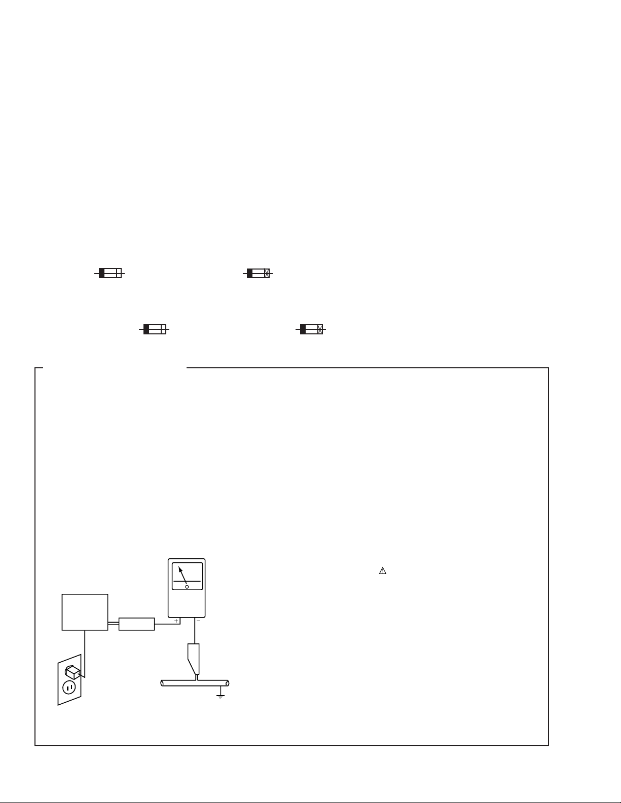
LEAKAGE CURRENT CHECK
Measure leakage current to a known earth ground (water
pipe, conduit, etc.) by connecting a leakage current tester
such as Simpson Model 229-2 or equivalent between the
earth ground and all exposed metal parts of the appliance
(input/output terminals, screwheads, metal overlays, control
shaft, etc.). Plug the AC line cord of the appliance directly
into a 120V AC 60Hz outlet and turn the AC power switch
on. Any current measured must not exceed 0.5mA.
Reading should
not be above
0.5mA
Earth
ground
Device
under
test
Also test with
plug reversed
(Using AC adapter
plug as required)
Test all
exposed metal
surfaces
Leakage
current
tester
ANY MEASUREMENTS NOT WITHIN THE LIMITS
OUTLINED ABOVE ARE INDICATIVE OF A POTENTIAL
SHOCK HAZARD AND MUST BE CORRECTED BEFORE
RETURNING THE APPLIANCE TO THE CUSTOMER.
2. PRODUCT SAFETY NOTICE
Many electrical and mechanical parts in the appliance
have special safety related characteristics. These are
often not evident from visual inspection nor the protection
afforded by them necessarily can be obtained by using
replacement components rated for voltage, wattage, etc.
Replacement parts which have these special safety
characteristics are identified in this Service Manual.
Electrical components having such features are identified
by marking with a
in this Service Manual.
The use of a substitute replacement component which does
not have the same safety characteristics as the PIONEER
recommended replacement one, shown in the parts list in
this Service Manual, may create shock, fire, or other hazards.
Product Safety is continuously under review and new
instructions are issued from time to time. For the latest
information, always consult the current PIONEER Service
Manual. A subscription to, or additional copies of, PIONEER
Service Manual may be obtained at a nominal charge from
PIONEER.
on the schematics and on the parts list
AC Leakage Test
2
VSX-D209, VSX-D209-G
2. EXPLODED VIEWS AND PARTS LIST
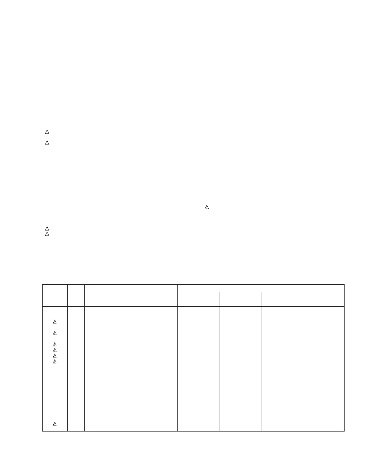
NOTES:• Parts marked by "NSP" are generally unavailable because they are not in our Master Spare Parts List.
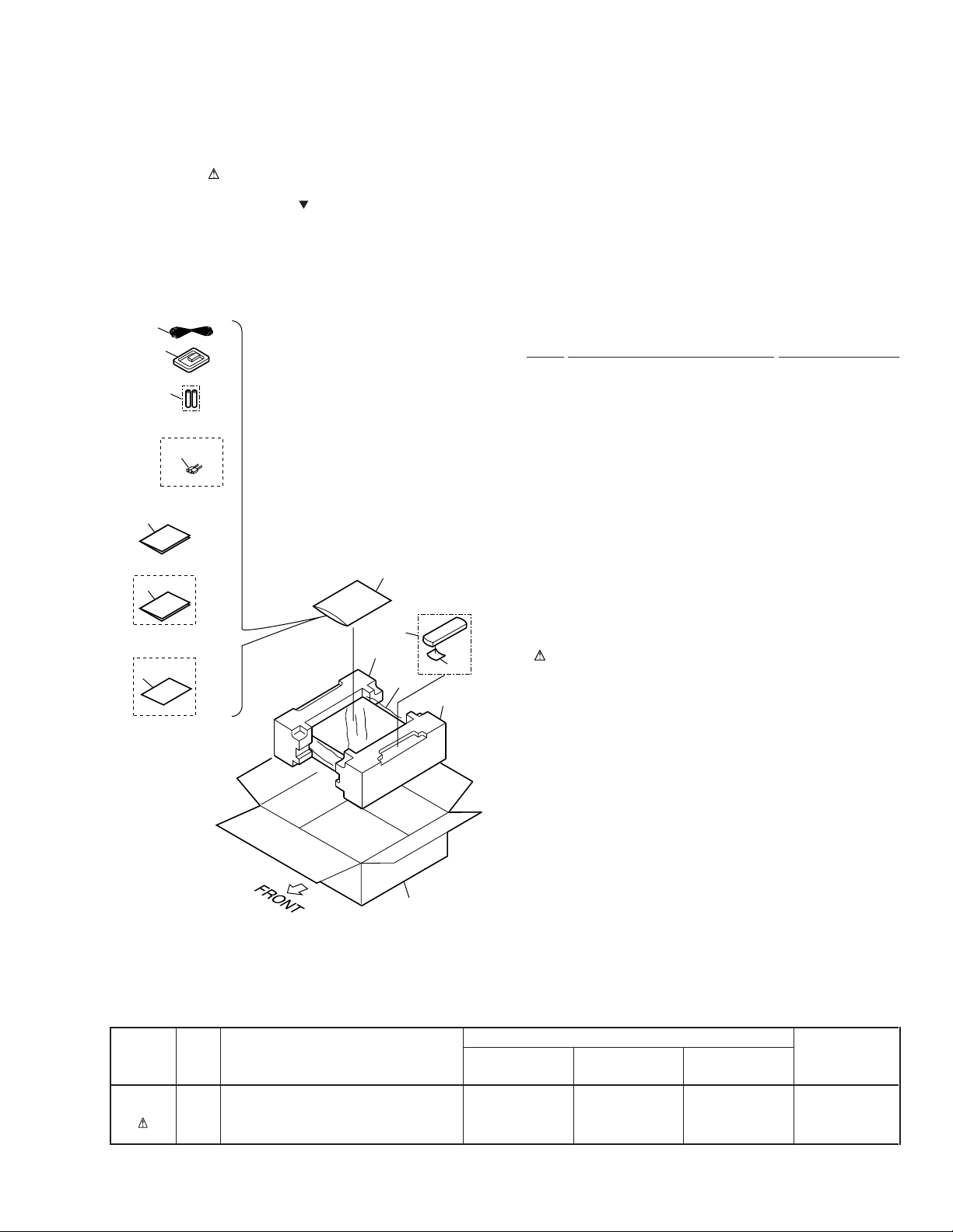
2.1 PACKING
The mark found on some component parts indicates the importance of the safety factor of the part.
•
Therefore, when replacing, be sure to use parts of identical designation.
Screws adjacent to mark on the product are used for disassembly.
•
1
2
7
BXJI Type Only
14
12
BXJI Type Only
13
BXJI Type Only
15
(1) PACKING PARTS LIST
Mark No. Description Part No.
1 FM Wire Antenna ADH7004
2 AM Loop Antenna ATB7009
3 Polyethylene Bag Z21-038
(0.03 × 230 × 340)
4 • • • • • •
5 Remote Control Unit AXD7245
(CU-VSX166)
NSP 7 Dry Cell Battery (R6P, AA) VEM-013
3
5
8
6
10
9
14 AC Plug Adapter See Contrast table (2)
6 Battery Cover RZN1156
8 Left Pad AHA7275
9 Right Pad AHA7276
10 Packing Sheet AHG7069
11 Packing Case See Contrast table (2)
12 Operating Instructions ARE7246
(English/Chinese)
13 Operating Instructions See Contrast table (2)
(Spanish)
15 Caution 220V Label See Contrast table (2)
11
(2) CONTRAST TABLE
VSX-D209/BXJI, VSX-D209-G/BXJI and VSX-D209-G/HLXJI are constructed the same except for the following :
Part No.
Mark No. Symbol and Description VSX-D209 VSX-D209-G VSX-D209-G Remarks
/BXJI /BXJI /HLXJI
11 Packing Case AHD7819 AHD7821 AHD7804
13 Operating Instructions (Spanish) ARC7278 ARC7278 Not used
14 AC Plug Adapter AKX7011 AKX7011 Not used
15 Caution 220V Label ARR1003 ARR1003 Not used
3
VSX-D209, VSX-D209-G
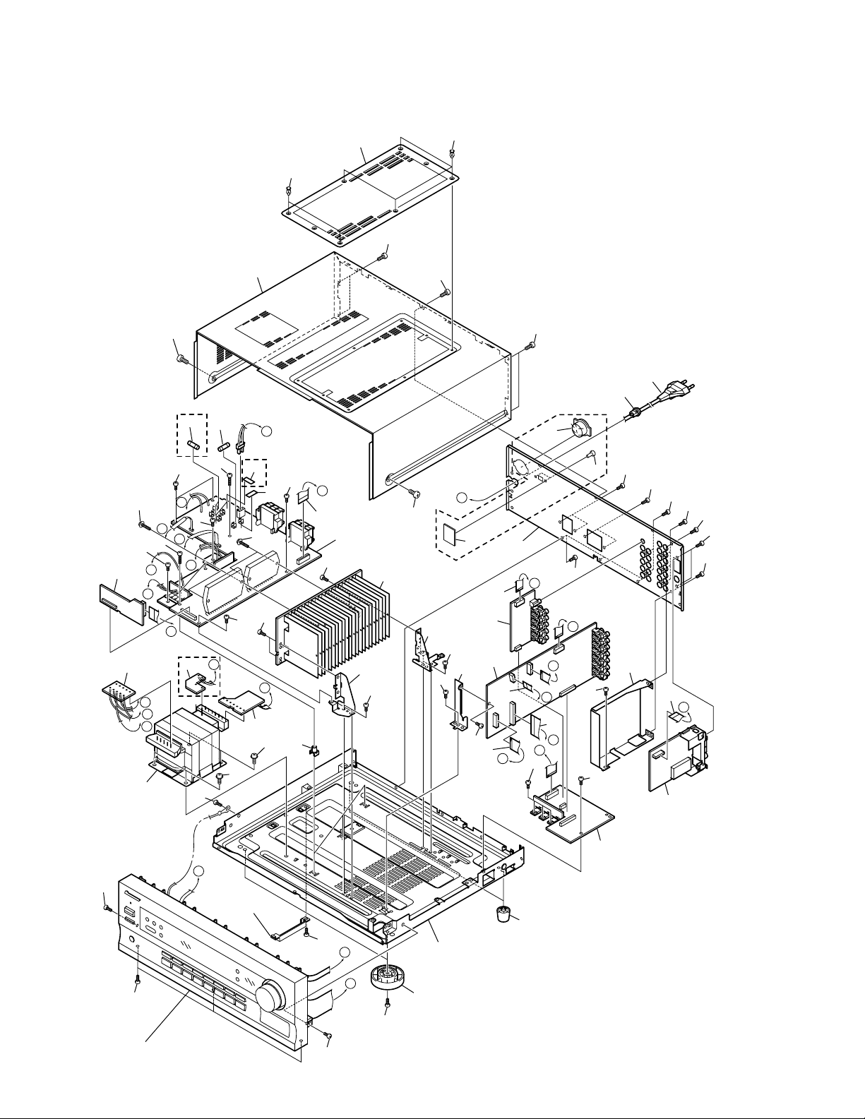
2.2 EXTERIOR SECTION
33
22
33
36
25
40
36
36
19
18
BXJI Type Only
41
BXJI
Type
Only
38
G
37
36
K
3
L
D
HLXJI
Type
9
Only
M
L
K
10
36
H
11
I
20
BXJI
42
38
Type
Only
35
36
17
36
36
C
I
40
4
21
24
36
30
36
E
36
36
36
36
36
36
37
J
36
M
14
36
36
29
2
F
36
8
J
H
28
36
36
6
34
39
39
36
26
36
16
1
13
E
A
36
27
15
F
12
B
C
D
36
36
7
5
G
36
Accessory of
Front Panel
32
36
A
B
36
23
31
36
Refer to
"2.3 FRONT PANEL SECTION".
36
4
VSX-D209, VSX-D209-G
(1) EXTERIOR SECTION PARTS LIST
Mark No. Description Part No. Mark No. Description Part No.
1 MAIN Assy AWX7471
2 VIDEO&6CH IN Assy AWX7383
NSP 3 AMP INPUT Assy AWX7382
4 AMP&PRIMARY Assy See Contrast table (2)
5 REGULATOR Assy AWX7389
6 TRANS 2 Assy AWX7391
7 FM/AM TUNER Unit AXX7047
NSP 8 TRANS 1 Assy See Contrast table (2)
NSP 9 TRANS 3 Assy AWX7392
10 Power Transformer See Contrast table (2)
11 Fuse (FU1) See Contrast table (2)
12 FFC (J31 : 30P/190 BD 60V) ADD7186
(MAIN CN102 ↔ FRONT CN402)
13 FFC (J32 : 8P/170 BD 60V) ADD7187
(MAIN CN103 ↔ FRONT CN401)
14 FFC (J33 : 12P/200 BD 60V) ADD7188
(MAIN CN104 ↔ VIDEO&6CH IN CN305)
15 FFC (J34 : 13P/80 BD 60V) ADD7189
(MAIN CN105 ↔ FM/AM TUNER CN1)
16 FFC (J35 : 17P/110 BD 60V) ADD7190
(MAIN CN106 ↔ AMP INPUT CN290)
17 FFC (J36 : 18P/80 BD 60V) ADD7191
(REGULATOR CN801 ↔ AMP&PRIMARY CN53)
18 Strain Relief CM-22B
19 AC Power Cord See Contrast table (2)
20 Voltage Selector See Contrast table (2)
NSP 21 VOLTAGE SELECT SW Assy See Contrast table (2)
22 Top Cover See Contrast table (2)
NSP 23 Under Base 409 ANA7094
24 R Panel See Contrast table (2)
25 Bonnet Case See Contrast table (2)
26 PCB Angle ANG7253
27 Shield R3 ANG7277
28 Heat Sink Angle F ANG7251
29 Heat Sink Angle R ANG7252
NSP 30 Heat Sink 0.8 ANH7110
31 Insulator See Contrast table (2)
32 Foot Assy REC1263
33 Push Rivet See Contrast table (2)
34 PCB Mold AMR2533
NSP 35 Fuse Card See Contrast table (2)
36 Screw BBZ30P080FMC
37 Screw BBZ30P200FMC
38 Screw ABA7043
39 Screw FBT40P080FZK
40 Screw See Contrast table (2)
41 Fuse (FU2, FU3) See Contrast table (2)
NSP 42 Fuse Card See Contrast table (2)
(2) CONTRAST TABLE
VSX-D209/BXJI, VSX-D209-G/BXJI and VSX-D209-G/HLXJI are constructed the same except for the following :
Part No.
Mark No. Symbol and Description VSX-D209 VSX-D209-G VSX-D209-G Remarks
/BXJI /BXJI /HLXJI
NSP 8 TRANS 1 Assy Not used Not used AWX7390
NSP 21 VOLTAGE SELECT SW Assy AWX7442 AWX7442 Not used
NSP 35 Fuse Card AAX7098 AAX7098 AAX7277
NSP 42 Fuse Card AAX7277 AAX7277 Not used
4 AMP&PRIMARY Assy AWX7473 AWX7473 AWX7388
10 Power Transformer ATS7261 ATS7261 Not used
(AC110V/120-127V/220V/240V)
10 Power Transformer (AC220-230V) Not used Not used ATS7259
11 Fuse (FU1 : T5A/250V) REK1029 REK1029 Not used
11 Fuse (FU1 : T2.5A/250V) Not used Not used REK1026
19 AC Power Cord VDG1080 VDG1080 VDG1061
20 Voltage Selector AKX-507 AKX-507 Not used
22 Top Cover AME7375 AME7376 AME7376
24 R Panel ANC7878 ANC7883 ANC7875
25 Bonnet Case AZN7779 AZN7819 AZN7819
31 Insulator AMR7198 PNW2766 PNW2766
33 Push Rivet AEC7025 AEC7205 AEC7205
40 Screw FBT40P080FZK FBT40P080FNI FBT40P080FNI
41 Fuse (FU2, FU3 : T2.5A/250V) REK1026 REK1026 Not used
5
VSX-D209, VSX-D209-G
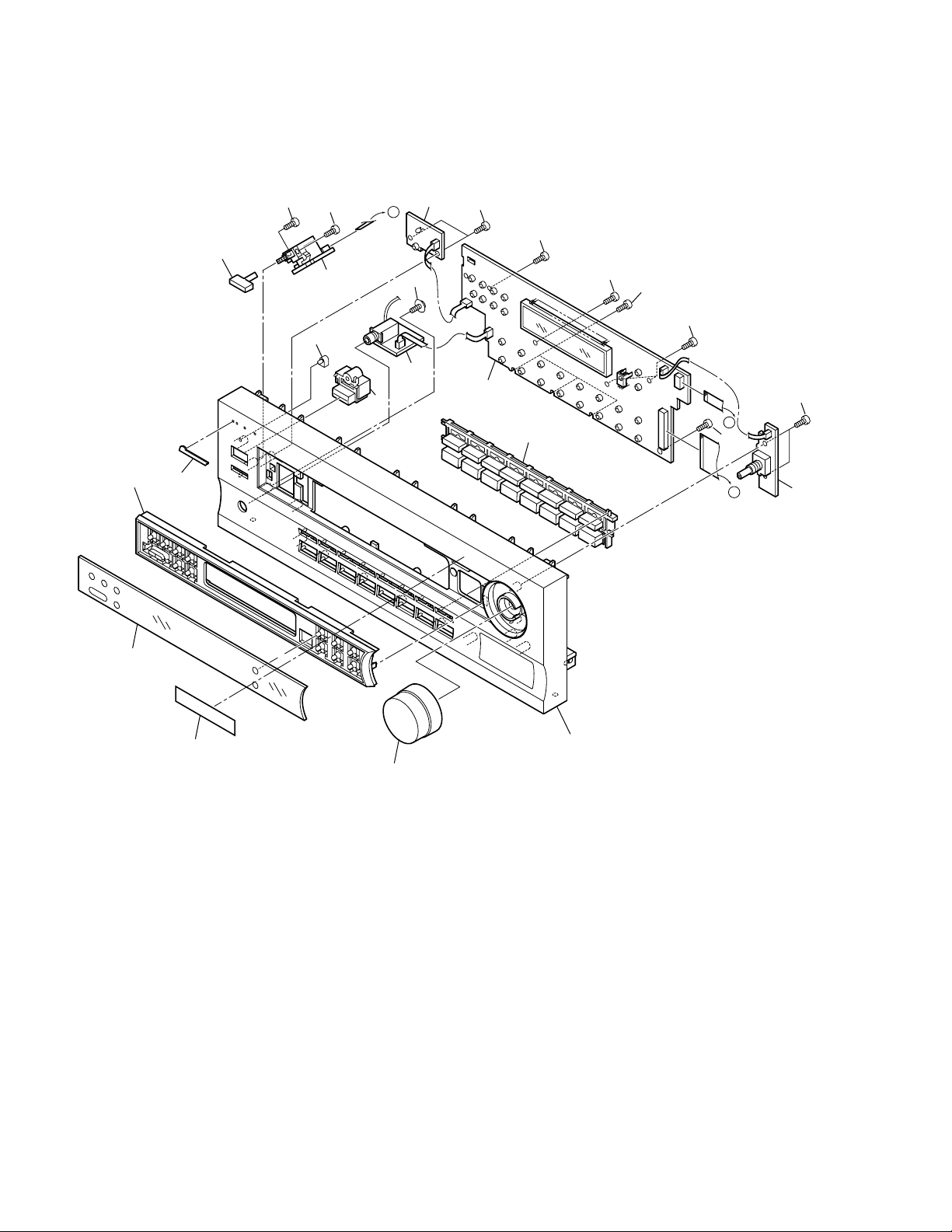
2.3 FRONT PANEL SECTION
11
13
16
16
8
5
14
7
2
G
17
4
16
16
16
16
16
1
10
A
16
B
16
3
9
15
6
12
6
(1) FRONT PANEL SECTION PARTS LIST
VSX-D209, VSX-D209-G
Mark No. Description Part No.
1 FRONT Assy AWX7472
2 POWER SW Assy AWX7385
NSP 3 R. ENCODER Assy AWX7386
NSP 4 H.P. Assy AWX7387
5 MECHA SW Assy AWX7443
6 Volume Knob See Contrast table (2)
7 Power Button See Contrast table (2)
8 Power Button M See Contrast table (2)
9 Window See Contrast table (2)
10 F Button See Contrast table (2)
Mark No. Description Part No.
11 Sub Panel 409RDS AAD7552
12 F Panel See Contrast table (2)
13 Name Plate See Contrast table (2)
14 LED Lens PNW2019
NSP 15 Getter D209HL AAX7744
16 Screw PPZ30P080FMC
17 Screw ABA7009
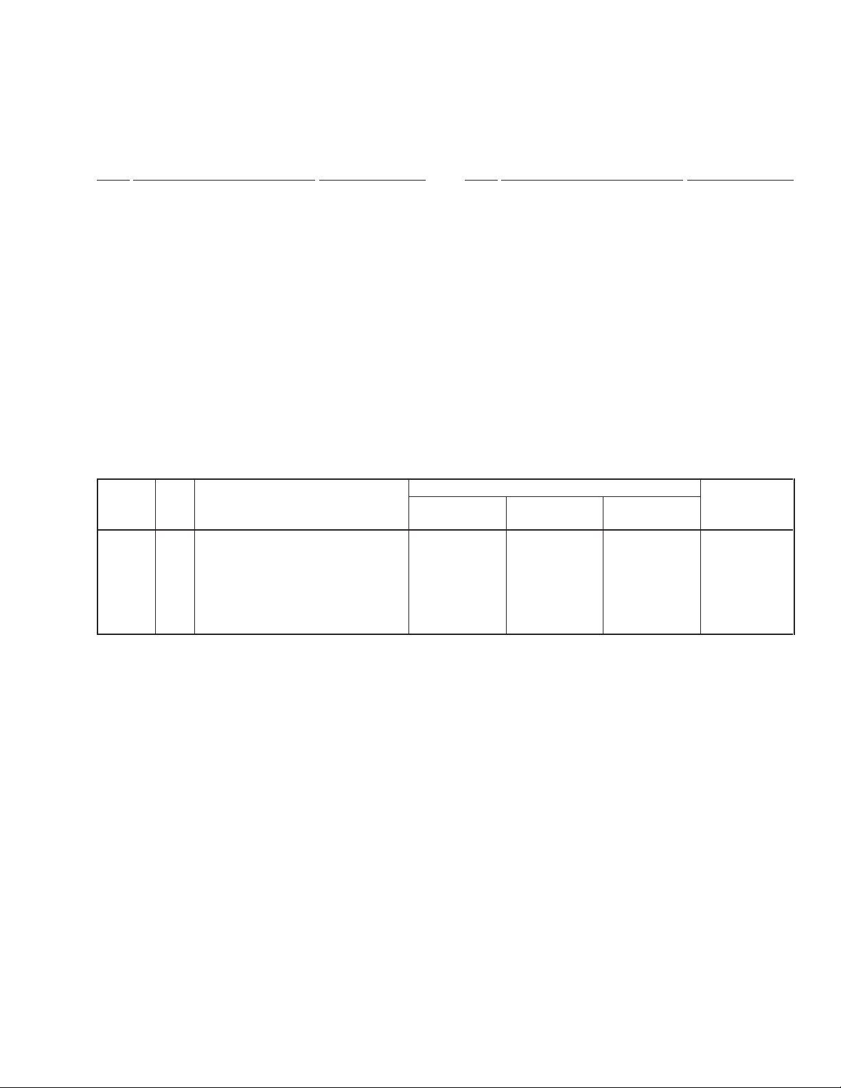
(2) CONTRAST TABLE
VSX-D209/BXJI, VSX-D209-G/BXJI and VSX-D209-G/HLXJI are constructed the same except for the following :
Part No.
Mark No. Symbol and Description VSX-D209 VSX-D209-G VSX-D209-G Remarks
/BXJI /BXJI /HLXJI
6 Volume Knob AAB7179 AAB7180 AAB7180
7 Power Button AAD7440 AAD7485 AAD7485
8 Power Button M AAD7442 AAD7491 AAD7491
9 Window AAK7709 AAK7714 AAK7714
10 F Button AAD7537 AAD7556 AAD7556
12 F Panel AMB7653 AMB7659 AMB7659
13 Name Plate PAM1776 PAM1779 PAM1779
7
1
23
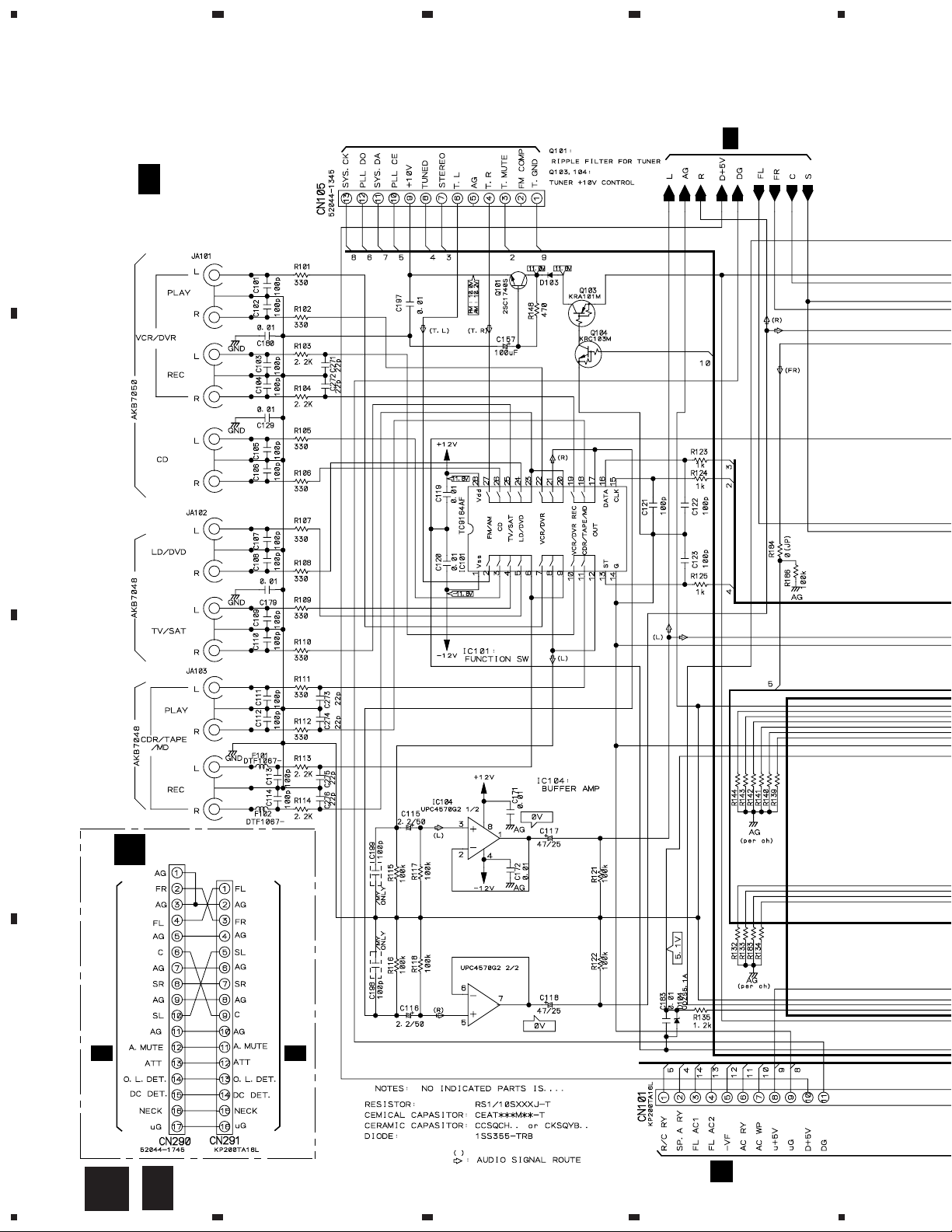
VSX-D209, VSX-D209-G
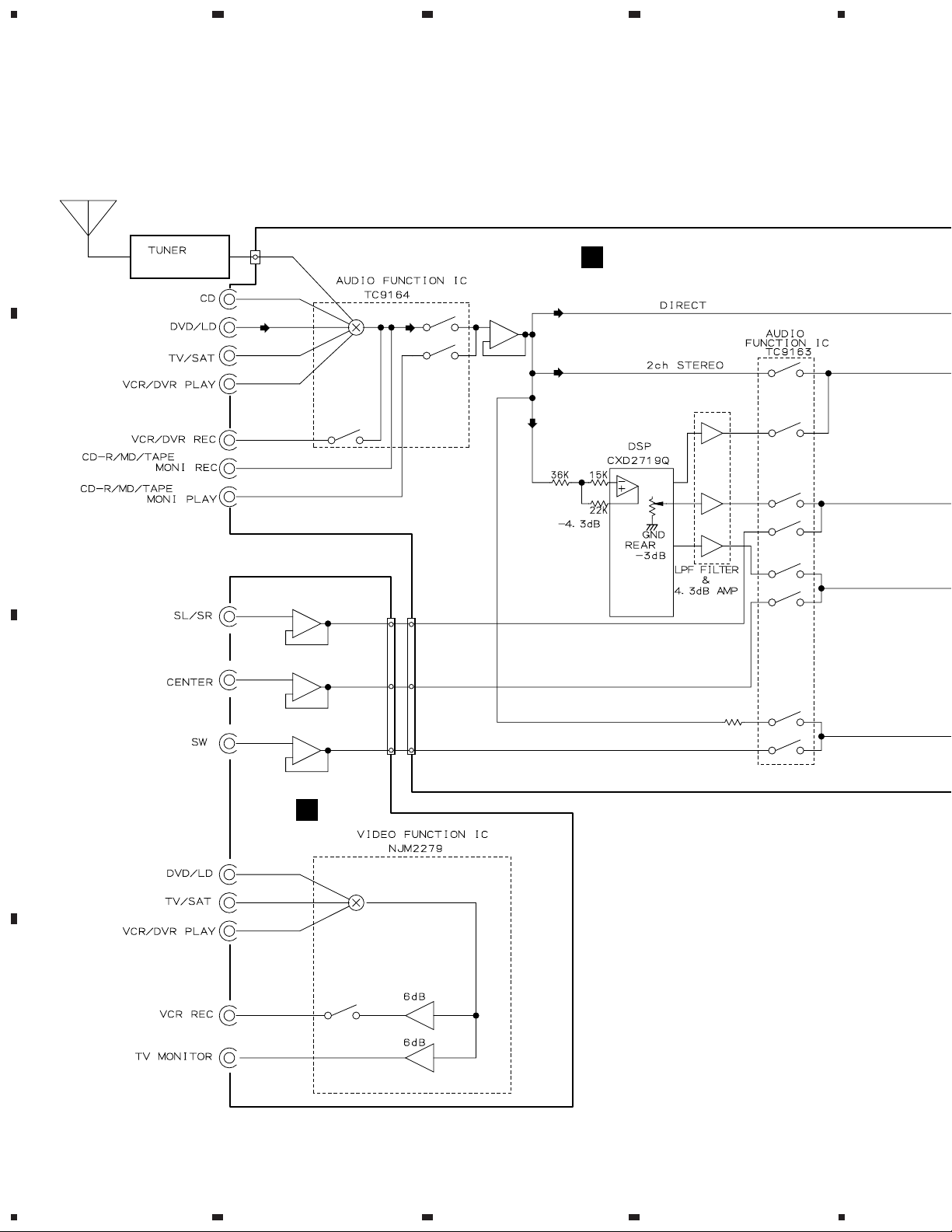
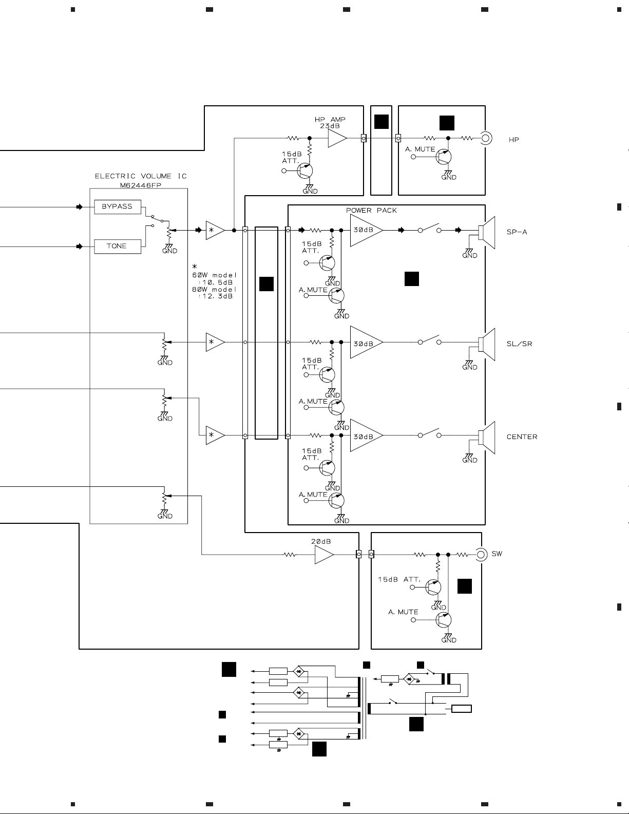
3. BLOCK DIAGRAM AND SCHEMATIC DIAGRAM
A
3.1 BLOCK DIAGRAM
4
UNIT
AXX7047
B
CN105
6
5
5
3
5
4
7
10
IC303
IC302
IC101
2
611
CN305
7
CN104
77
7
11
11
IC104
8
3
1
B
IC102
3
IC202
IC201
38
39
314
43
IC203
35
351
IC203
30
7
8
7
18
19
5
9
17
11
12
10
3
IC302
9
1
9
C
H
1
3
12
5
10
IC301
D
8
1234
5
678
VSX-D209, VSX-D209-G
IC108
J43
CN102
57
IC103
Q105
17
IC105
31
57
15
4
CN106
601
1
22
Q603
A
Q601
9
11
IC106
34
57
33
10 5
24
Q653
K
3
IC601
551
4
15
C
IC602
26
I
Q551
RY751
RY753
A
B
IC107
5 7
6
36
69
+B
-B
+B
-B
FL AC
FL AC
+12V
-12V
Q701
Q702
IC801
IC802
E
POWER AMP
IC601, IC602
CN402
K
CN101
B
Q651
18
Q632
Q631
CN1041CN305
31
IC107
D701
D702
D801–D804
F
IC602
14
1
CN101
B
U+5V
IC51
RY51
T1
POWER
TRANSFORMER
Q304
D51-D54
C
RY752
Q303
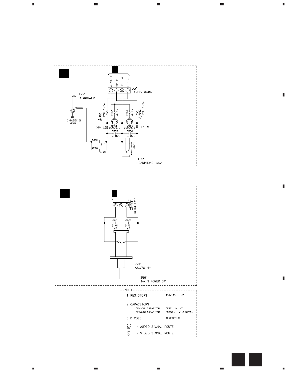
S591
J
T51
H
AC IN
C
D
9
5
6
7
8
1
23
VSX-D209, VSX-D209-G
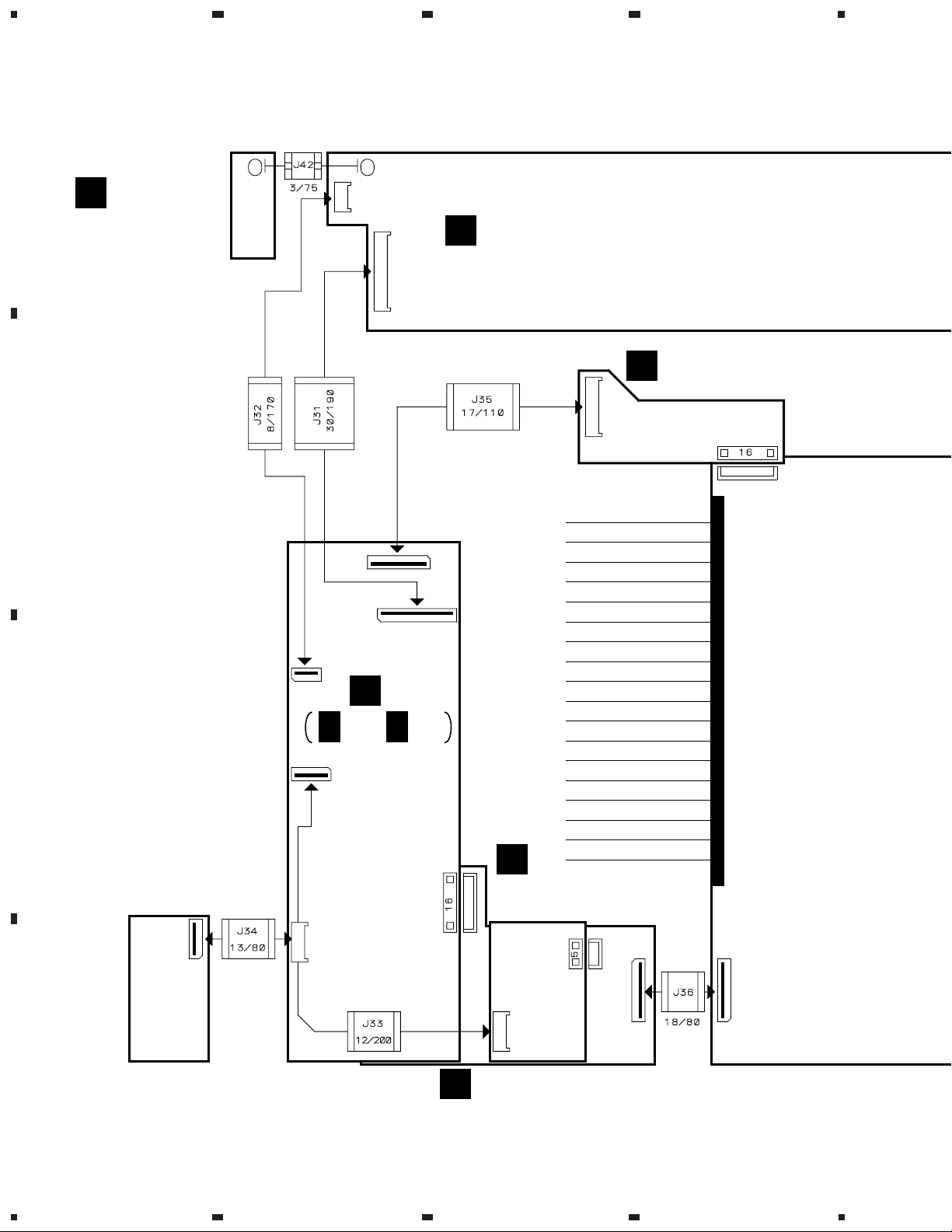
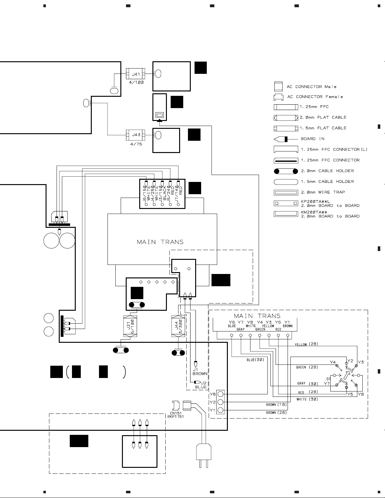
3.2 OVERALL WIRING CONNECTION DIAGRAM
4
A
R.ENCODER
L
511
ASSY
(AWX7386)
CN401
491
FRONT ASSY
K
(AWX7472)
CN402
AMP INPUT ASSY
A
(AWX7382)
CN290
CN291
B
CN601
CN106
CN102
CN103
B
B 1/2, B 2/2
C
CN104
MAIN ASSY
(AWX7471)
H
VIDEO&6CH IN ASSY
CN101
CN105
FM/AM
TUNER
UNIT
(AXX7047)
D
F
(AWX7383)
CN802
CN305
CN306
CN803
CN801
REGULATOR ASSY
(AWX7389)
CN53
10
1234
5
678
VSX-D209, VSX-D209-G
Note : When ordering service parts, be sure to refer to "EXPLODED VIEWS and P AR TS LIST" or "PCB PARTS LIST".
A
403
471
CN591
501
551
POWER SW ASSY
M
(AWX7385)
MECHA SW ASSY
J
(AWX7443)
I
H.P.
ASSY
(AWX7387)
E
TRANS3
ASSY
B
(AWX7392)
J6
J7
J3
TRANS2
ASSY
(AWX7391)
J5
J4
701
C
C 1/2, C 2/2
AMP&PRIMARY ASSY
(BXJI TYPE : AWX7473)
(HLXJI TYPE : AWX7388)
BXJI TYPE ONLY
D
J12 J11 J13
851
J44
HLXJI
TYPE
ONLY
GA
J1J2
TRANS1 ASSY
(AWX7390)
BXJI TYPE ONLY
VOLTAGE SELECT SW
(AKX-507)
C
D
GB
VOLTAGE SELECT
SW ASSY
(AWX7442)
5
J12 J11 J13
11
6
7
8
1
23
VSX-D209, VSX-D209-G
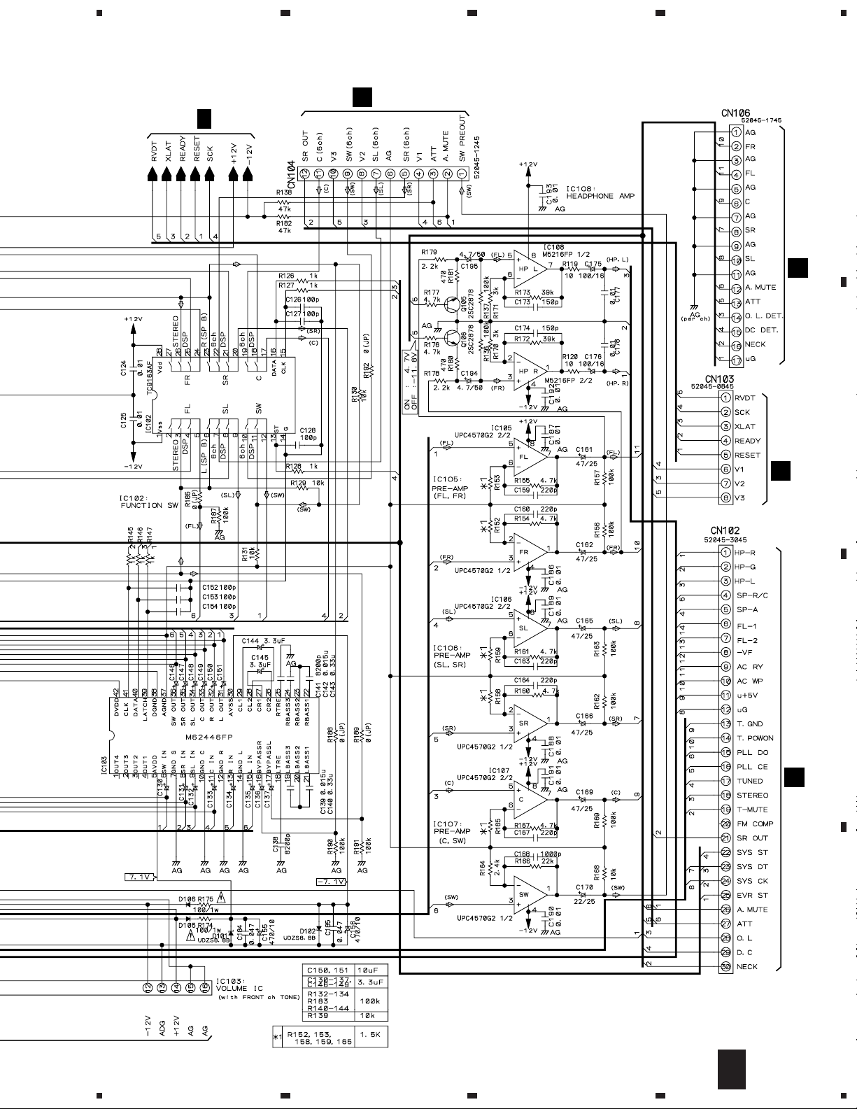
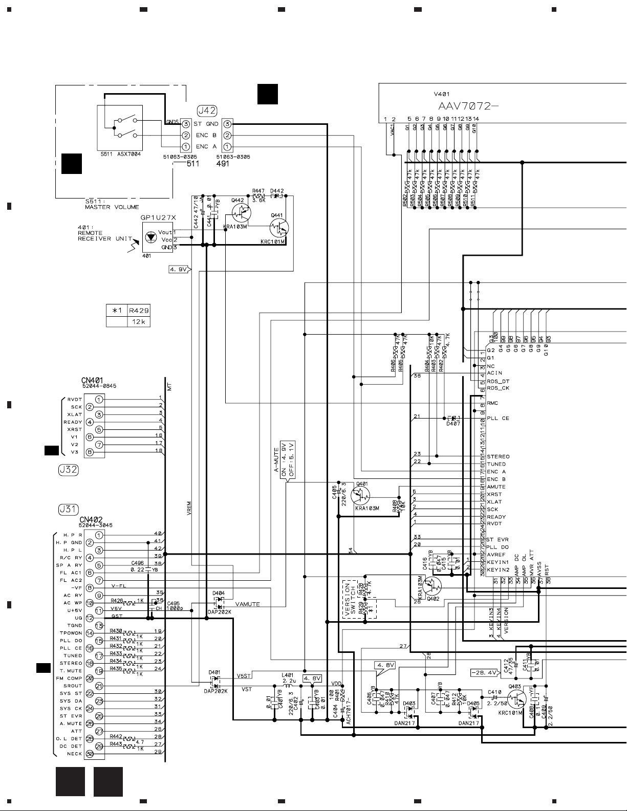
3.3 AMP INPUT and MAIN (1/2) ASSYS
4
FM/AM TUNER UNIT
A
B 1/2
B
MAIN ASSY
(AWX7471)
B 2/2
C
AMP INPUT ASSY
A
CN106
D
12
B 1/2
A
B
1234
(AWX7382)
1/2
CN601
C 1/2
F
CN802
5
B 2/2
678
VSX-D209, VSX-D209-G
CN305
H
A
CN290
A
B
CN401
K
CN402
K
C
D
1/2
B
5
6
7
8
13
1
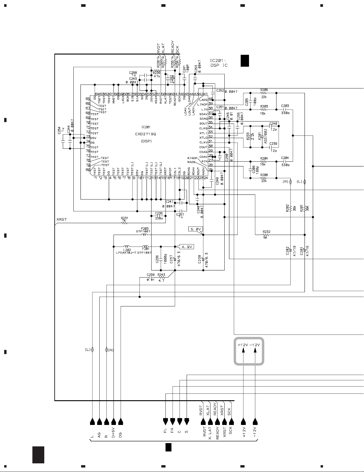
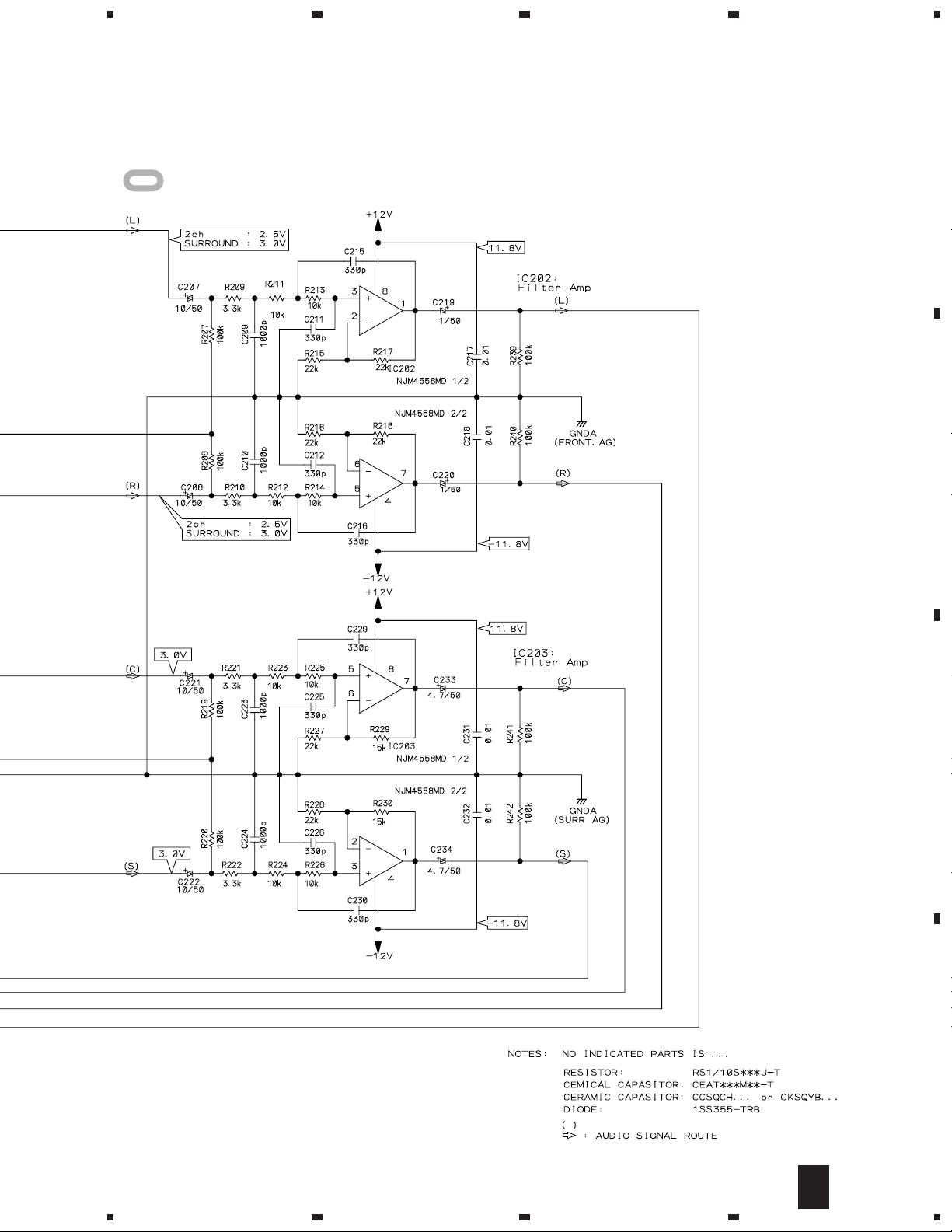
VSX-D209, VSX-D209-G
3.4 MAIN ASSY (2/2)
23
4
A
B
B 2/2
MAIN ASSY
(AWX7471)
C
D
B 1/2
14
2/2
B
1234
5
: The power supply is shown with the marked box.
678
VSX-D209, VSX-D209-G
A
B
C
D
2/2
B
5
6
7
8
15
1
23
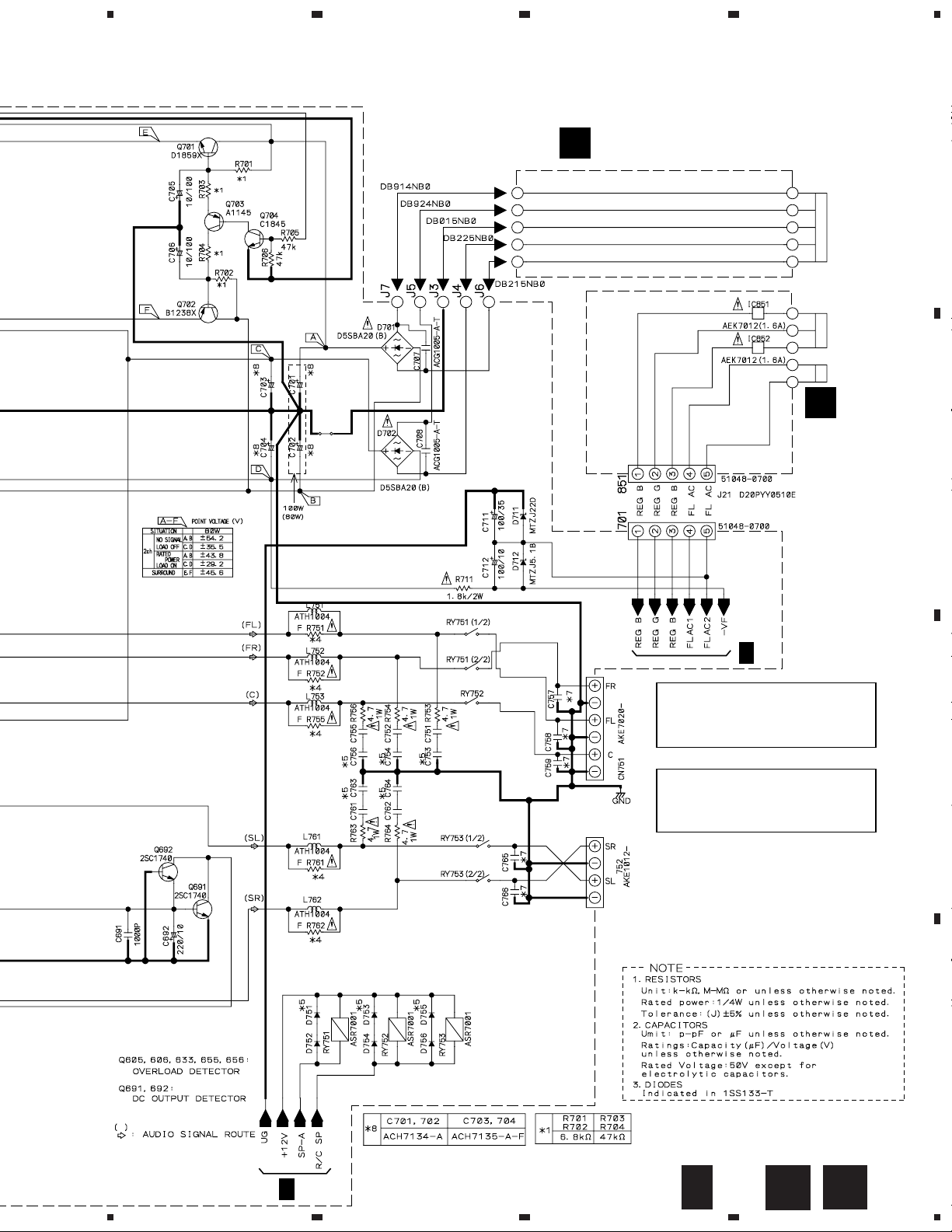
VSX-D209, VSX-D209-G
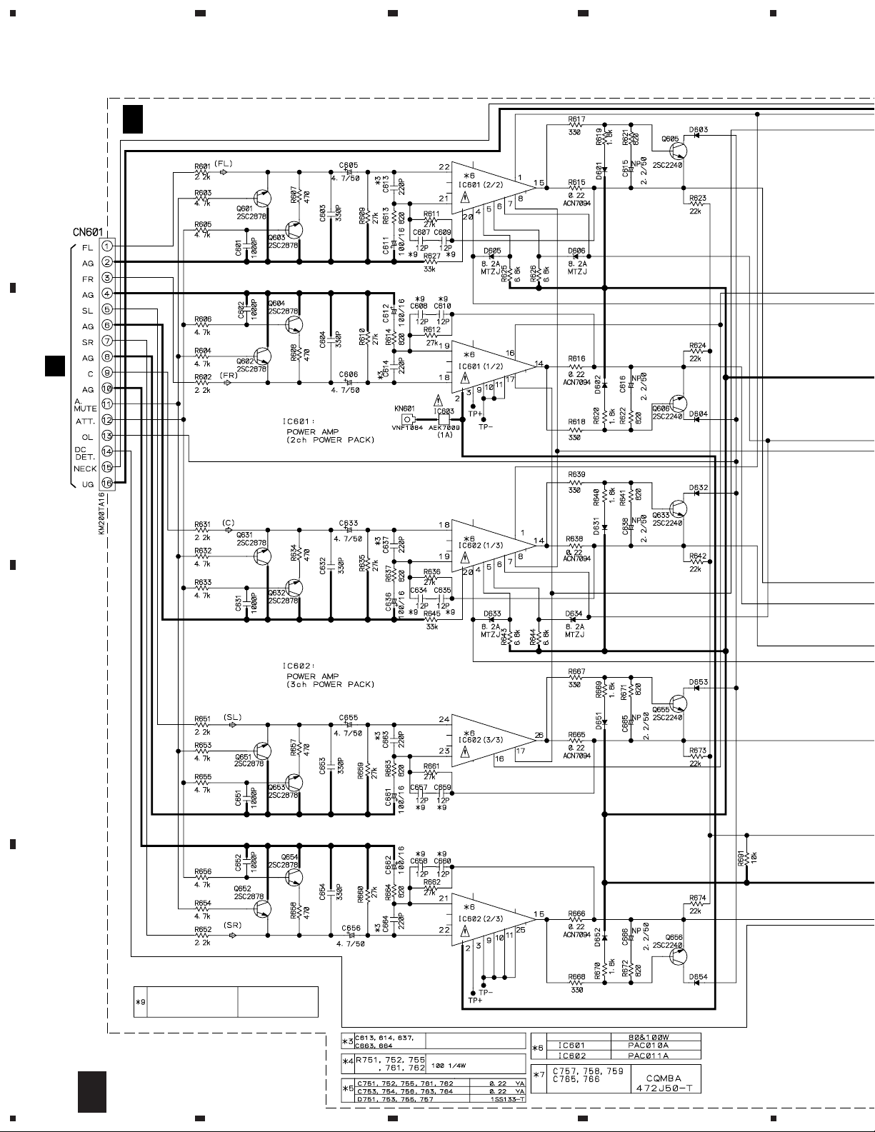
3.5 AMP&PRIMARY (1/2), TRANS2 and TRANS3 ASSYS
4
C 1/2
A
CN291
(BXJI : AWX7473) (HLXJI : AWX7388)
A
B
AMP&PRIMARY ASSY
C
D
16
C
1234
1/2
C607, C608, C609, C610,
C634, C635,
C657, C658, C659, C660
BXJI TYPE : 6P
HLXJI TYPE : 12P
HLXJI TYPE ONLY
HLXJI TYPE ONLY
5
678
VSX-D209, VSX-D209-G
TRANS3 ASSY
E
(AWX7392)
POWER TRANSFORMER
A
D
TRANS2
ASSY
(AWX7391)
B
C 2/2
CAUTION : FOR CONTINUED PROTECTION
CAUTION : FOR CONTINUED PROTECTION
AGAINST RISK OF FIRE.
REPLACE ONLY WITH SAME TYPE
NO. 49101.6 FOR IC851 AND IC852
MFD, BY LITTELFUSE INC.
AGAINST RISK OF FIRE.
REPLACE ONLY WITH SAME TYPE
NO. 491001 FOR IC603, 491.315 FOR
IC52 MFD, BY LITTELFUSE INC.
C
D
C 2/2
5
6
7
C
1/2
D
E
8
17
1
23
4
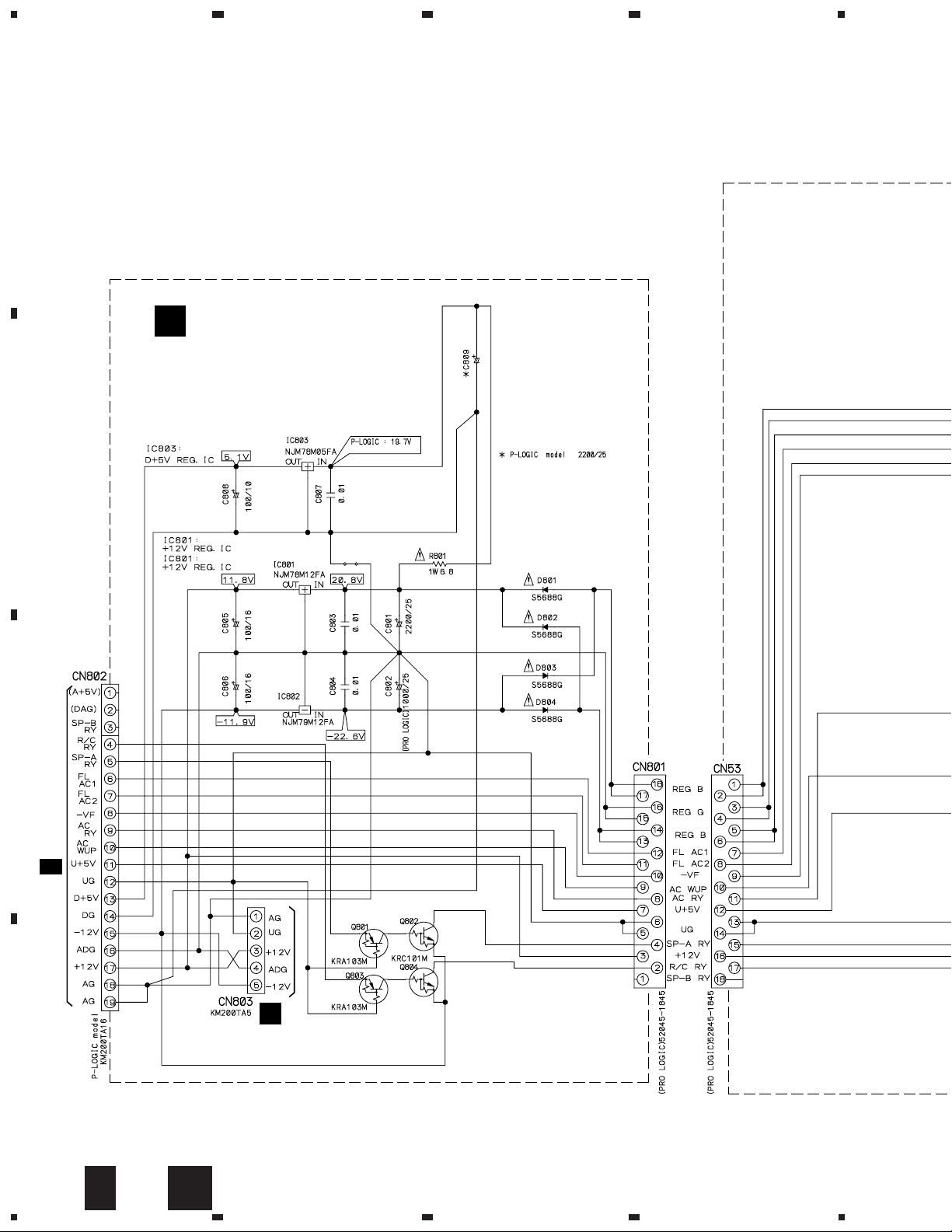
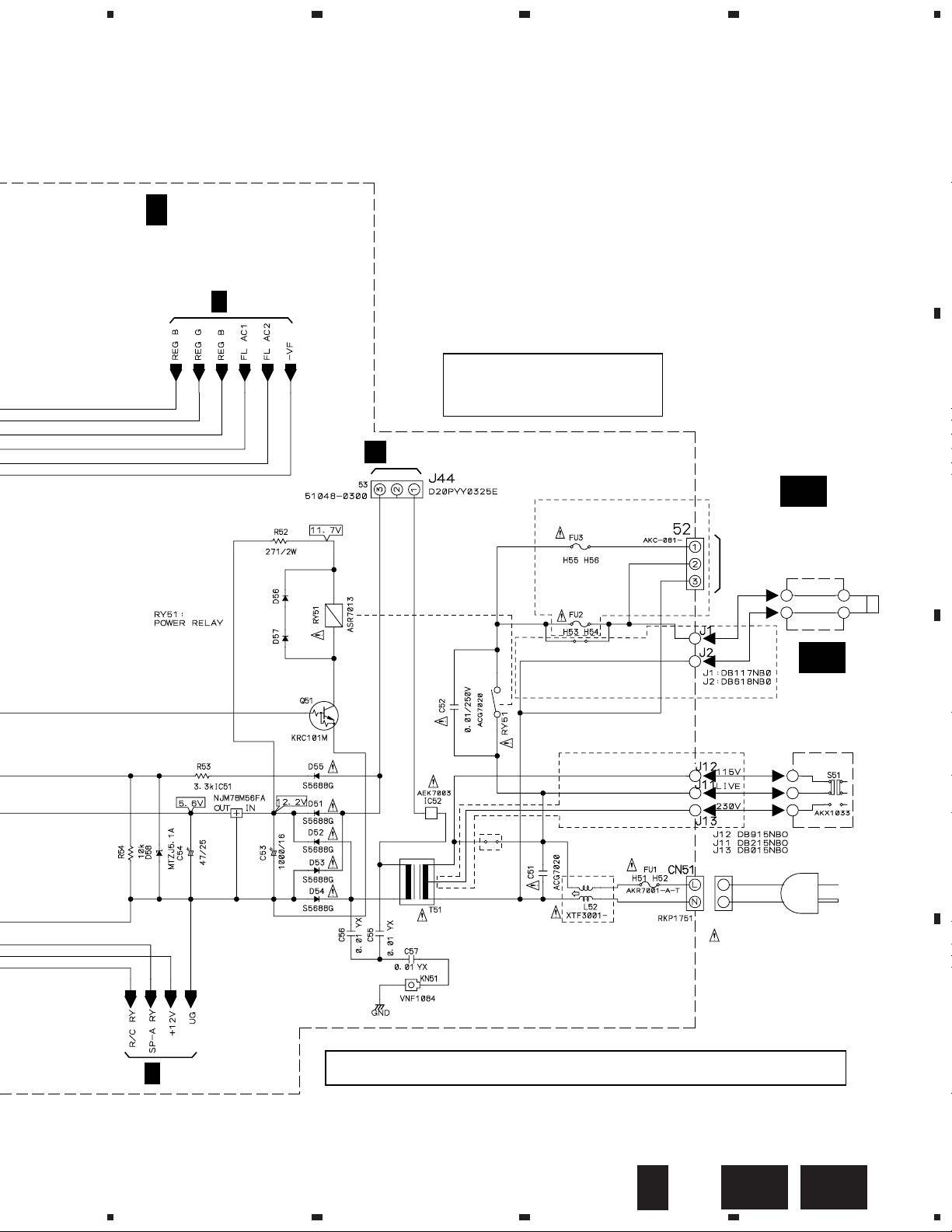
VSX-D209, VSX-D209-G
3.6 AMP&PRIMARY (2/2), REGULATOR, TRANS1 and VOLTAGE SELECT SW ASSYS
A
REGULATOR ASSY
F
(AWX7389)
B
C
CN101
B 1/2
H
CN306
D
18
2/2
C
1234
F
5
C 2/2
AMP&PRIMARY ASSY
(BXJI : AWX7473)
(HLXJI : AWX7388)
C 1/2
678
VSX-D209, VSX-D209-G
A
J
CN591
CAUTION : FOR CONTINUED PROTECTION
AGAINST RISK OF FIRE.
REPLACE ONLY WITH SAME TYPE
NO. 491.315 FOR IC52 MFD, BY
LITTELFUSE INC.
BXJI TYPE ONLY
REK1026 (T2.5A)
REK1026 (T2.5A)
HLXJI TYPE ONLY
GA
TRANS1
ASSY
(AWX7390)
HLXJI TYPE ONLY
VOLTAGE SELECT
SW (AKX-507)
VOLTAGE
SELECT SW
ASSY
BXJI TYPE ONLY
(AWX7442)
GB
BXJI TYPE ONLY
B
POWER TRANSFORMER
C
C 1/2
BXJI : REK1029 (T5.0A)
HLXJI
TYPE
ONLY
BXJI : ATT7038
HLXJI :ATT7037
• NOTE FOR FUSE REPLACEMENT
CAUTION -
5
FOR CONTINUED PROTECTION AGAINST RISK OF FIRE.
REPLACE WITH SAME TYPE AND RATINGS ONLY.
6
HLXJI : REK1026 (T2.5A)
2/2
C
7
LIVE
NEUTRAL
AC POWER CORD
BXJI : VDG1080
HLXJI : VDG1061
D
GBGA
8
19
1
23
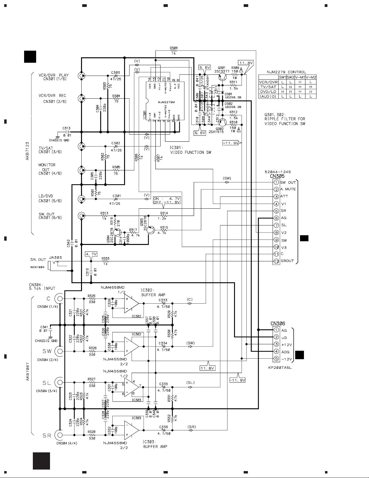
VSX-D209, VSX-D209-G
3.7 VIDEO&6CH IN, H. P. and MECHA SW ASSYS
VIDEO&6CH IN ASSY
H
A
B
(AWX7383)
4
CN104
B 1/2
C
CN803
F
D
20
H
1234
1
H.P. ASSY
I
(AWX7387)
234
VSX-D209, VSX-D209-G
A
403
K
B
J
MECHA SW ASSY
(AWX7443)
C 2/2
J44
C
D
JI
1
2
3
4
21
1
23
VSX-D209, VSX-D209-G
3.8 FRONT, R. ENCODER and POWER SW ASSYS
FRONT ASSY
A
R.ENCODER
L
ASSY
(AWX7386)
B
K
(AWX7472)
4
CN103
B 1/2
C
CN102
B 1/2
D
22
K
L
1234
5
678
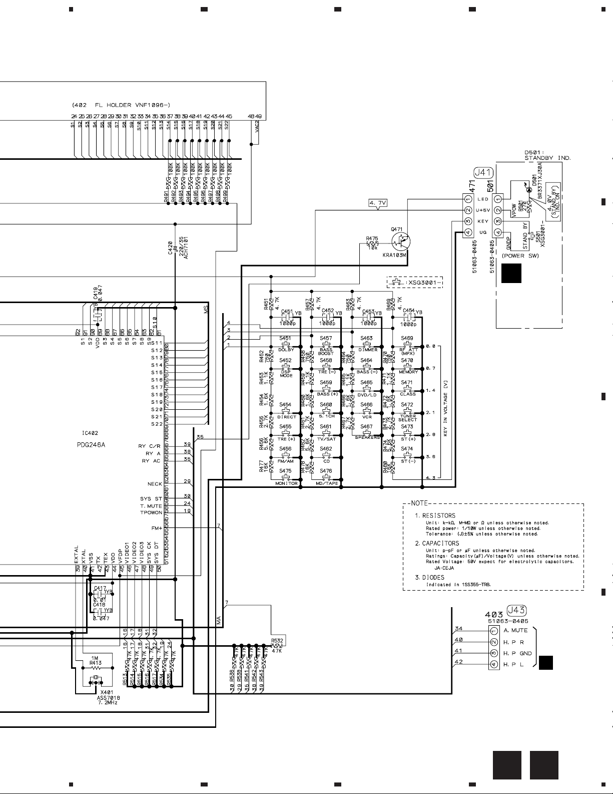
VSX-D209, VSX-D209-G
FRONT ASSY
S451 : DOLBY PRO LOGIC
S452 : DSP MODE
S454 : DIRECT
S455 : TREBLE (+)
S456 : FM/AM
S457 : S.BASS
S458 : TREBLE (–)
S459 : BASS (+)
S460 : DVD 5.1CH
S461 : TV/SAT
S462 : CD
S463 : FL DIMMER
S464 : BASS (–)
S465 : DVD/LD
S466 : VCR/DVR
S467 : SPEAKERS
S469 : RF ATT
S470 : MEMORY
S471 : CLASS
S472 : TUNING SELECT
S473 : STATION (+)
S474 : STATION (–)
S475 : MONITOR
S476 : CD-R/TAPE MD
A
M
POWER
SW ASSY
(AWX7385)
B
C
551
I
D
MK
5
6
7
8
23
1
23
VSX-D209, VSX-D209-G
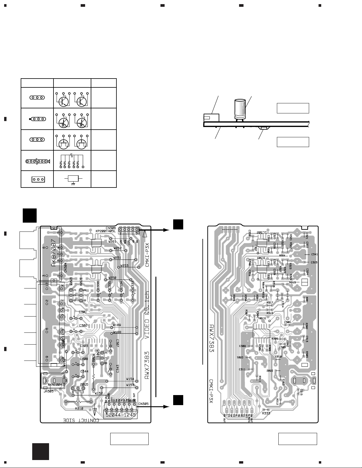
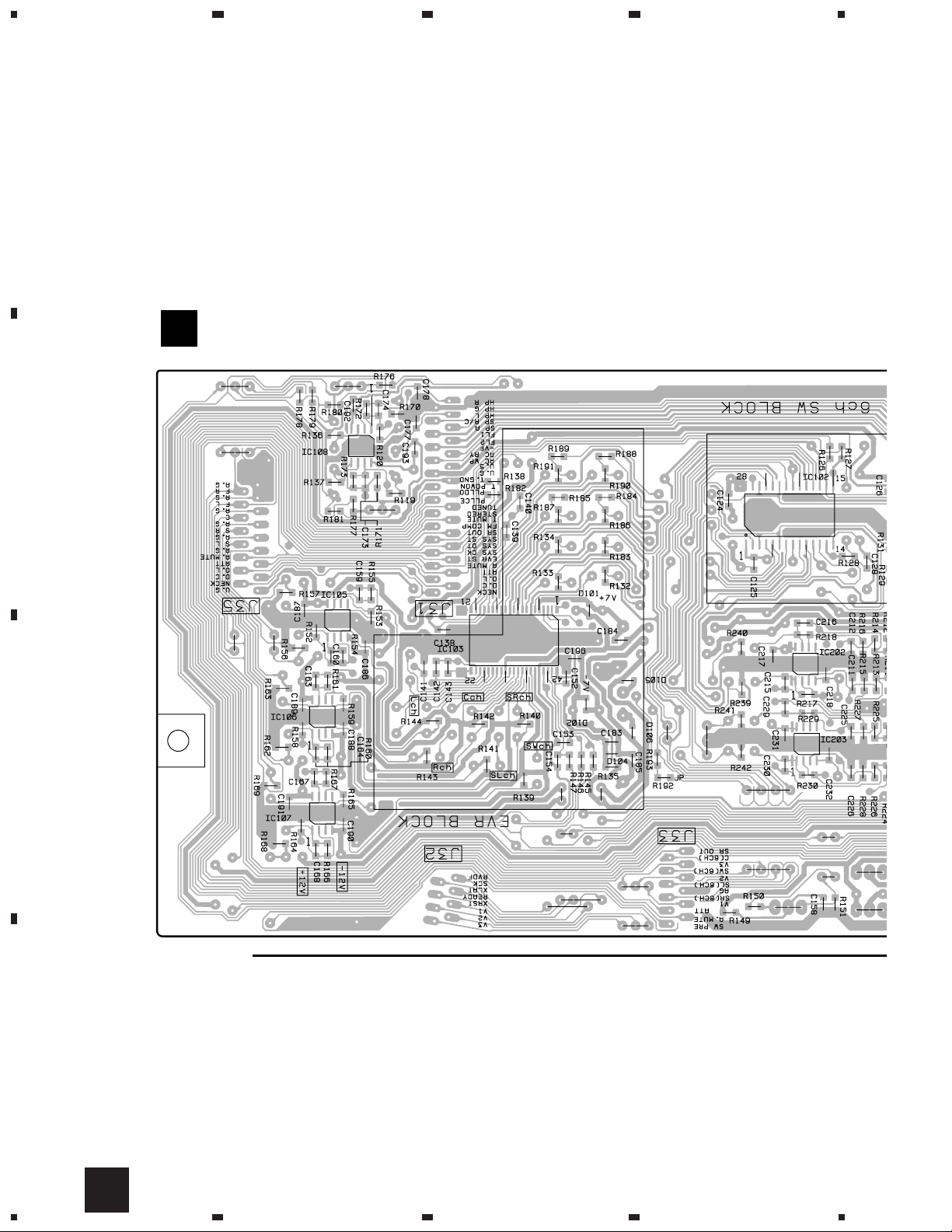
4. PCB CONNECTION DIAGRAM
NOTE FOR PCB DIAGRAMS :
1. Part numbers in PCB diagrams match those in the schematic
A
diagrams.
2. A comparison between the main parts of PCB and schematic
diagrams is shown below.
Symbol In PCB
Diagrams
BCE
BCE
D
Symbol In Schematic
Diagrams
BCEBCE
BCE
DGGSS
BCE
DGS
Part Name
Transistor
Transistor
with resistor
Field effect
transistor
Resistor array
4
3. The parts mounted on this PCB include all necessary parts for
several destinations.
For further information for respective destinations, be sure to
check with the schematic diagram.
4. View point of PCB diagrams.
Connector
Capacitor
SIDE A
P.C.Board
Chip Part
SIDE B
B
4.1 VIDEO&6CH IN ASSY
VIDEO&6CH IN ASSY
H
C
3-terminal
regulator
Q303
Q304
F
CN803
IC302
IC303
IC301
Q301
Q302
D
B
CN104
24
(ANP7330-B)
SIDE A
H
1234
(ANP7330-B)
SIDE B

1
234
VSX-D209, VSX-D209-G
4.2 TRANS2, TRANS3, REGULATOR and TRANS1 ASSYS
REGULATOR ASSY
F
Q805
Q803
Q806
Q801
Q804
Q802
IC804
B
CN101
A
(ANP7331-B)
SIDE A
CN306
H
Line Voltage Selection
Line Voltage can be changed by the following modification:
1. Disconnect the AC power cord.
2. Remove the cover.
3. Change the connection wire from TRANS 1 ASSY to
AMP&PRIMARY ASSY (Terminal No. J1) as follows.
Voltage Terminal No.
220-230V J1 of TRANS 1 ASSY
240V 240V terminal of power transformer
C
CN53
POWER TRANSFORMER
IC803
IC802
IC801
220-230V
TRANS3 ASSY
E
J6 J4 J3 J5 J7
C
240V
B
C
4. Stick a line voltage label on the rear panel.
Description Part No.
220V label AAX-193
240V label AAX-192
GA
1
TRANS1 ASSY
(HLXJI TYPE ONLY)
220-230V
C
2
J1 J2
240V
DB825EB0
TRANS2 ASSY
D
D
3
D
701
C
FE
GA
4
25
1
23
4
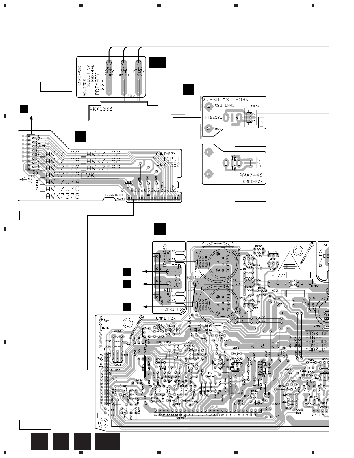
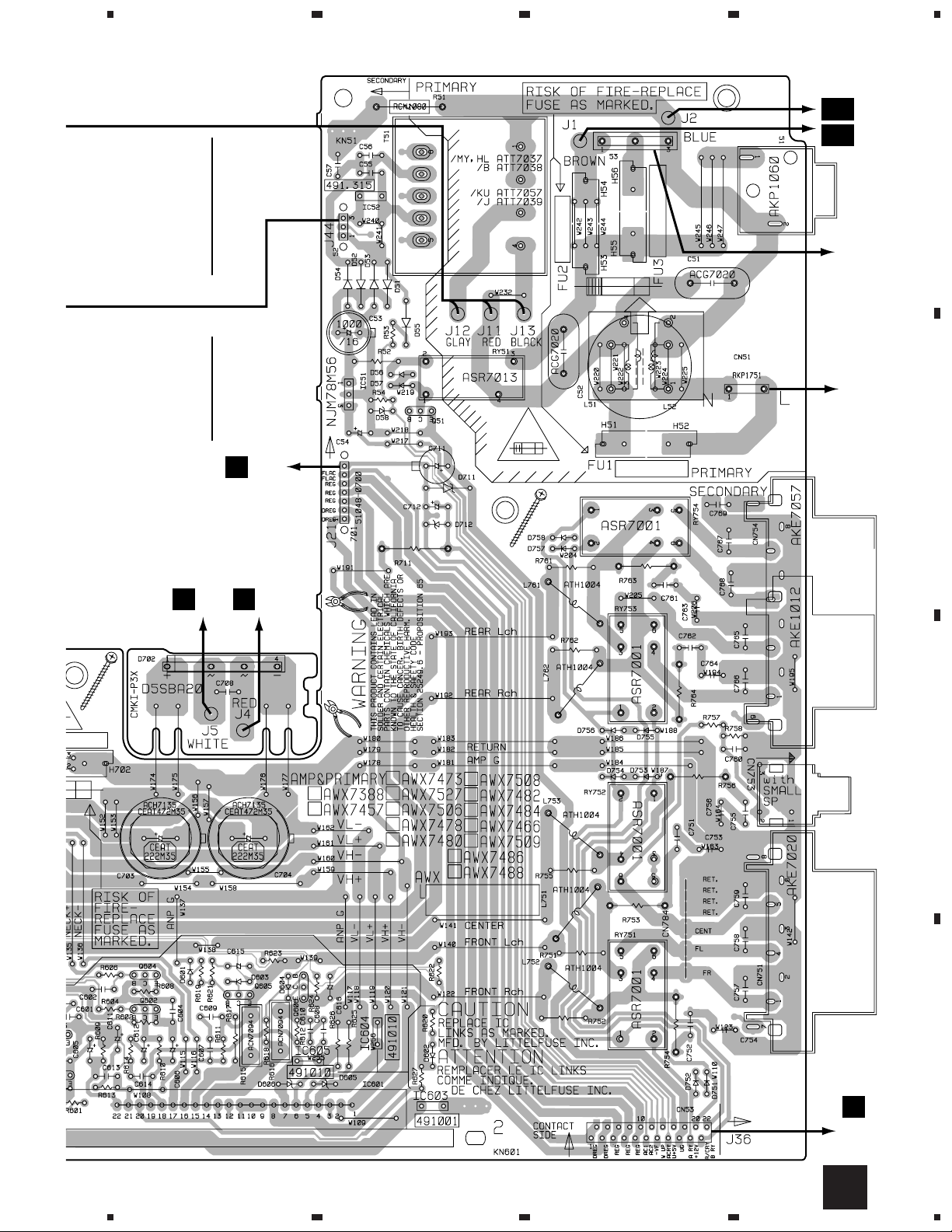
VSX-D209, VSX-D209-G
4.3 AMP INPUT, AMP&PRIMARY, MECHA SW and VOLTAGE SELECT SW ASSYS
A
GB
(ANP7331-B)
SIDE A
CN106
B
AMP INPUT ASSY
A
B
VOLTAGE
SELECT SW ASSY
(BXJI TYPE ONLY)
MECHA SW ASSY
J
(ANP7330-B)
SIDE A
(ANP7330-B)
SIDE B
(ANP7331-B)
SIDE A
AMP&PRIMARY ASSY
C
Q704
Q702
Q703
J6
E
C
Q701
Q655
Q691
Q631
Q632
Q633
Q692
Q656
Q604
Q652
Q654
Q651
D
Q653
Q606
Q605
Q602
Q603
E
E
J7
J3
(ANP7331-B)
SIDE A
26
A C
IC601
IC602
IC603
J
1234
GB
IC52
5
678
VSX-D209, VSX-D209-G
J2
GA
J1
GA
(HLXJI TYPE
ONLY)
VOLTAGE
SELECT
SW
(BXJI TYPE
ONLY)
A
E
IC51
Q51
J5
D
E
851
J4
AC IN
NEUTRAL LIVE
B
C
D
F
CN801
C
5
6
7
8
27
1
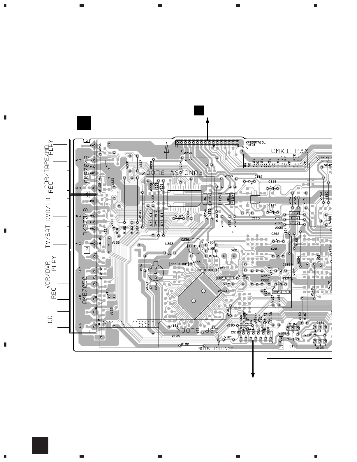
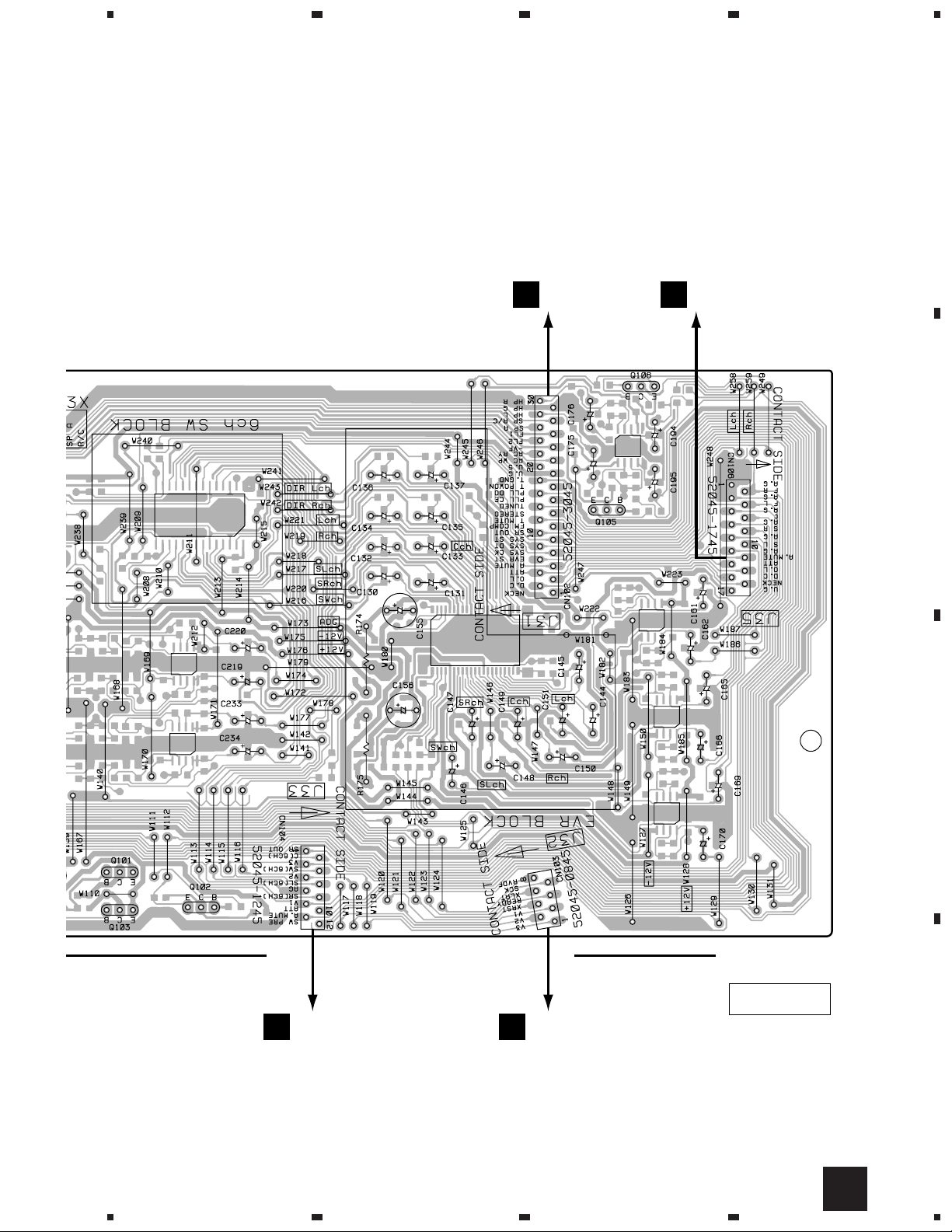
VSX-D209, VSX-D209-G
4.4 MAIN ASSY
A
B
23
MAIN ASSY
B
CN802
F
4
C
Q101Q104
Q103
FM/AM TUNER UNIT
D
28
B
1234
5
678
VSX-D209, VSX-D209-G
A
CN402
K
CN290
A
B
Q101
Q103 Q102
C
Q105 Q106
(ANP7330-B)
SIDE A
CN305
H
5
6
CN401
K
D
B
7
8
29
1
VSX-D209, VSX-D209-G
A
B
B
23
MAIN ASSY
4
C
IC105
IC108
IC106
IC107
D
30
B
1234
IC103
IC102
IC202 IC203
 Loading...